

Page 1
USER MANUAL
www.mopec.com
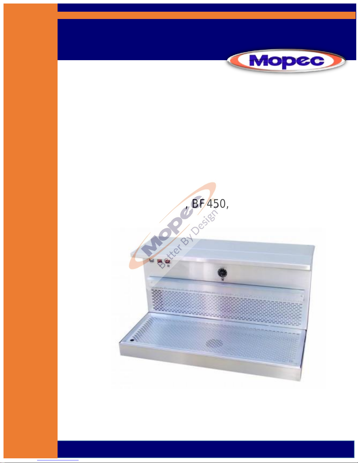
BF Series
Down/Back Draft Workstations
BF400, BF450, BF500, BF510, BF550
Rev 10-28-16 ©
Page 2
P a g e | 2
Page 3

P a g e | 3
TABLE OF CONTENTS
UNPACKAGING YOUR PRODUCT..…………………………………………………4
INSTALLATION………..…………………………………………………………….……..5
PRODUCT DRAWINGS
BF400 ROUGH IN……………………………………………………………..7
BF450 ROUGH IN……………………………………………………………..8
BF500 ROUGH IN (w Optional Leg Frame)..……………………..9
BF510 ROUGH IN…………………………………………………..………..10
BF550 ROUGH IN ………………………………………………..………….11
INTRODUCTION ……………………………………………………..…………………..12
PRODUCT DRAWINGS
BF400 …………………………………………………….……………………..13
BF450 …………………………………………………….……………………..14
BF500 …………………………… ……….…………….………………………15
BF510 ……………………………………………………………………………16
BF550 ……………………………………………………………………………17
FEATURES………………………………………………………………………………….18
AIR HANDLING………………………………………………..………………………..19
CLEANING AND MAINTENANCE
Filter information and evaluation………….……………..……….20
Stainless Steel Care and Maintenance………………………......21
Parts……………………………………………………..…………………..….24
Preventive Maintenance……………………….………………..…….25
WARRANTY……………………………………………………….………………..…….26
SAFETY LABELS……………………………………………………..…………..………27
TROUBLE SHOOTING GUIDE…………………………………………………..….28
ELECTRICAL DIAGRAM………………………………………….……………..…...29
CERTIFICATES……………………………………………………….……………..……30
Page 4

P a g e | 4
UNPACKING
1) Carefully inspect the exterior of the shipping container before opening. If the crate is damaged and the
product has sustained damage, then immediately contact Mopec and the freight carrier. Never discard the
shipping container even if it is damaged beyond recognition.
2) Have the delivery driver note any suspected damage on the Bill of Lading and sign it. Mopec will help assist in
filing a claim for product repair and/or replacement.
3) Carefully open the containers and inspect the equipment for concealed damage. If visible damage is noticed
(i.e. broken welds, dented stainless, scratches, etc.) follow through as noted above. Do not discard the
shipping material. They are important in settling claims.
CAUTION: There are loose components in the packaging of your product. Be very careful in examining the
packaging material as it may contain installation parts and/or product components.
INSPECTION
1) After carefully unpacking your Mopec workstation please inspect the items in the list below prior to installing
the unit. The workstation should be thoroughly checked for loose screws, defects, or damage that may have
occurred during shipping or packaging.
Page 5

P a g e | 5
INSTALLATION
BF Series Down and Back Draft Workstation Installation Instructions
Locate package of smaller items (dissection board, tissue boxes, or filters)
When removing from the shipping platform, be careful if the unit has a foot pedal. The unit should be removed from
the shipping platform as to not cause damage to the copper plumbing attached to the foot pedal
Leveling and Setting Unit in Place
The unit should be off the floor and resting on the leveling pads. The unit should be leveled to ensure proper drainage.
This allows water to evaporate or dry in case of a leak without getting trapped by the base of the unit Ensure there is a
Minimum of 6.5” from the wall to the back of the unit. This allows for elevating units to move freely without any
obstructions to the wall.
Utility Connections
The only connections necessary are the Electric, Cold and Hot water supply, the drain connection and the HVAC
connections if in house ventilation. The unit is already pre-wired and plumbed for the options ordered.
Electrical Connection
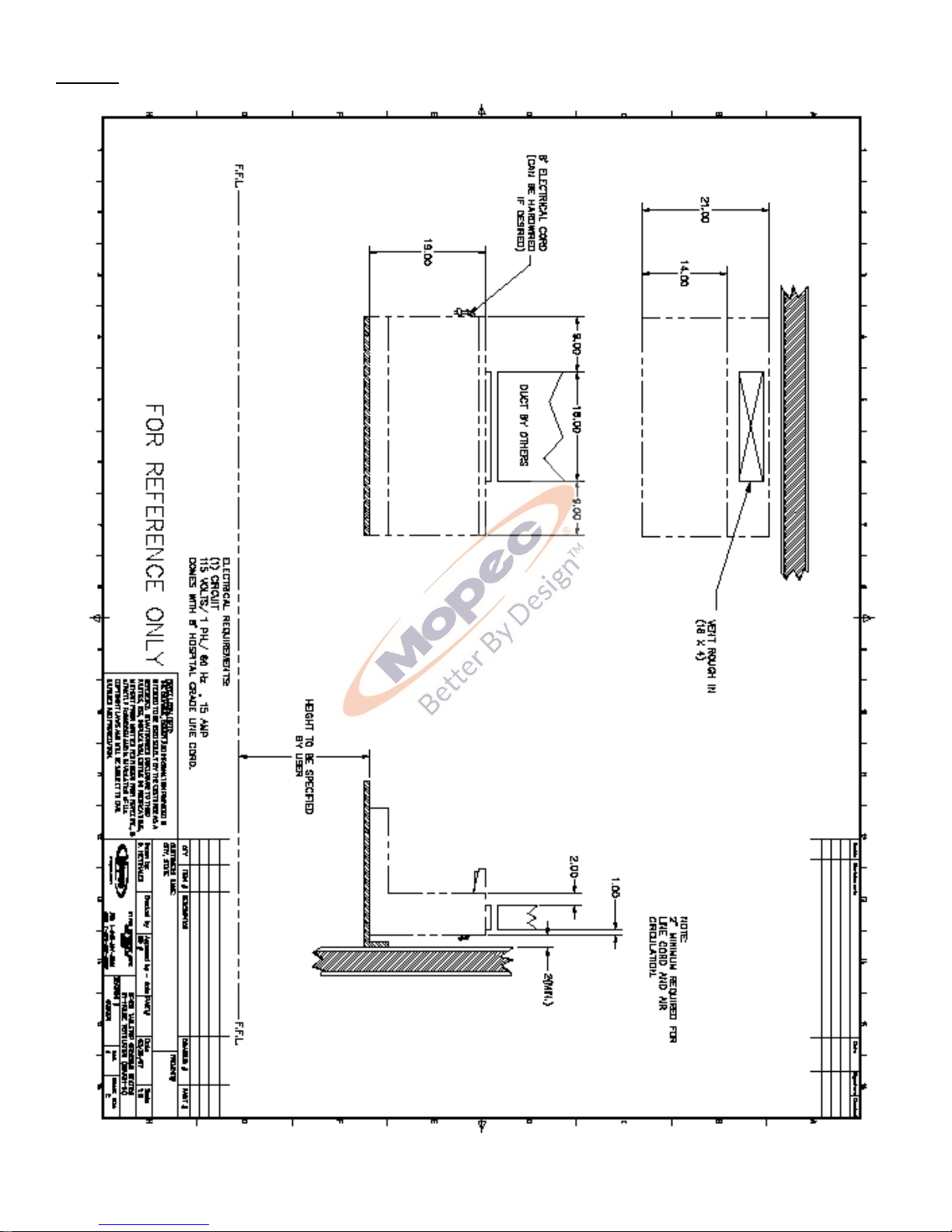
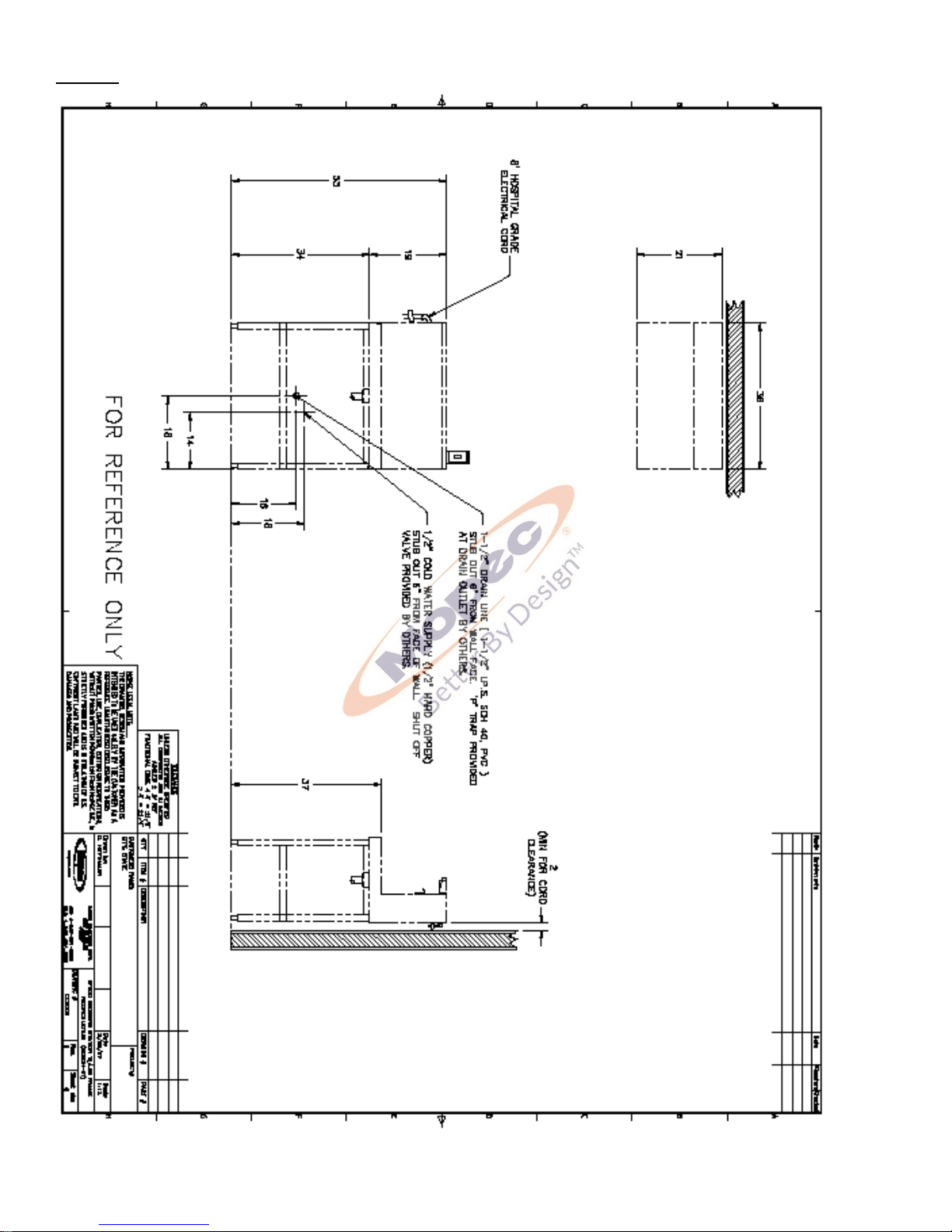
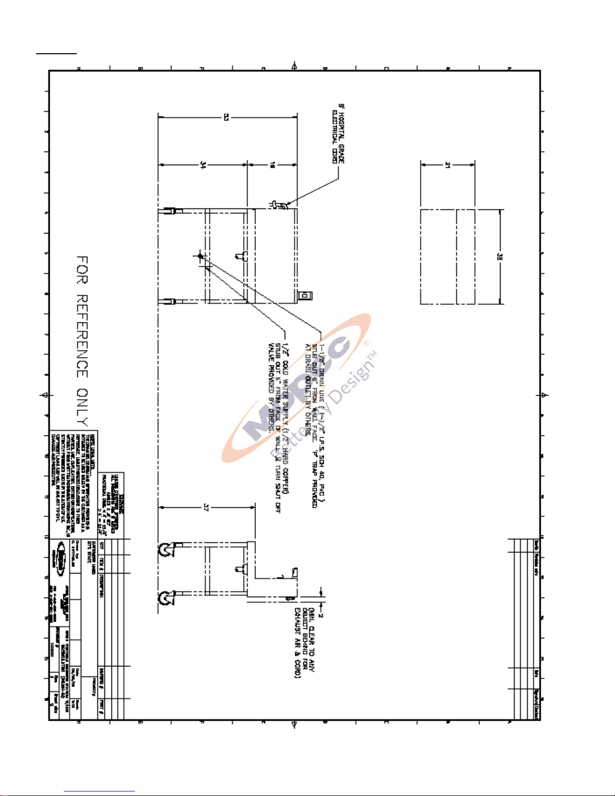
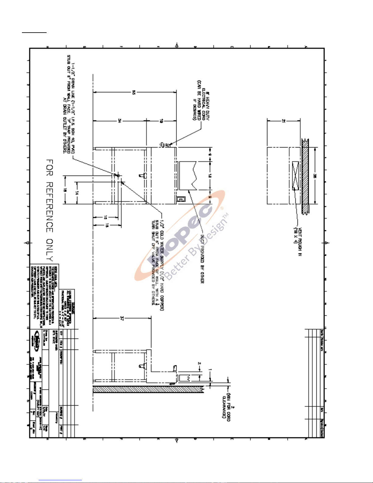
All electrical, water and ventilation stubs should be prepared in accordance with our rough-in dimensions shown on
rough in diagram from your approval process.
The electrical service provided for the MB600 must include:
1) A switch or circuit breaker for each circuit to which the wiring harnesses from the workstation will be
connected.
Each BF Series Workstation has a eight-foot line cord with a hospital grade plug. It is possible to order with a 3 foot
whip to permanently hard wire the unit to the electrical connection. The whip leads are labeled L1 and C1 for the unit
electrical options such as lights and fans if a recirculation unit.
There are three wires:
Black Labeled as L1
White Labeled as C1
Green w Yellow Stripe Ground
Flexible water tight conduit and connections are the preferred conduit and is not provided with the unit. This is due to
an unknown length needed and variances possible in the rough in process.
Drain Connection
The BF500, BF510 and BF550 workstations are equipped with 1.5” Diameter drain and connections. DO NOT modify
the drain line or connections without contacting MOPEC first. The Units are built in accordance with the rough in
drawings specific to the unit. The height is per the rough in drawings provided at the time of the order.
Water Supply Connection
The water supply connections are ½” DIA copper pipe. The unit has been cleared of water and debris during the
manufacturing and testing of the unit. The rough in drawing for the unit suggests a 1/4 turn valve to be connected to
the wall. This is to allow the water to be localized and disconnected should the need arise to work on plumbing in the
future. Before connecting the unit to the facility water supply, check the lines in the facility for debris by flushing the
lines for a moment. After the connections are made remove the aerator from the faucet and turn the water on and
open the faucet and other water options after the faucet to allow any debris to evacuate the system. This is the time
to look for leaks or other plumbing issues. The plumbing is tested for leaks and function at the facility and is put under
pressure for 45 minutes to check for leaks. However, the plumbing is hard copper and soldier connections. During
transport a unit may experience a failed soldier joint. Contact MOPEC immediately if there is a leak.
Page 6
P a g e | 6
Ventilation Connection
Ventilation is one of two types for the BF Workstations; In House Ventilation or Recirculation. For in house the unit is
connected to the facility ventilation system via duct work.
In House
BF450 the connection is a 4” x 18” rectangular stub on the top back of your unit. The duct work is not provided by
Mopec unless specifically ordered.
MB550 the connection is a 4” x 18” rectangular stub on the top back of your unit. The duct work is not provided by
Mopec unless specifically ordered.
Recirculation
BF400, BF500 and BF510 the filters will need to be installed. You should have a minimum of 2 inches or more behind
the workstation for the filtered air to discharge. Air flow is generated by multiple fans in the recirculation models. They
are controlled by a rheostat to control volume/speed.
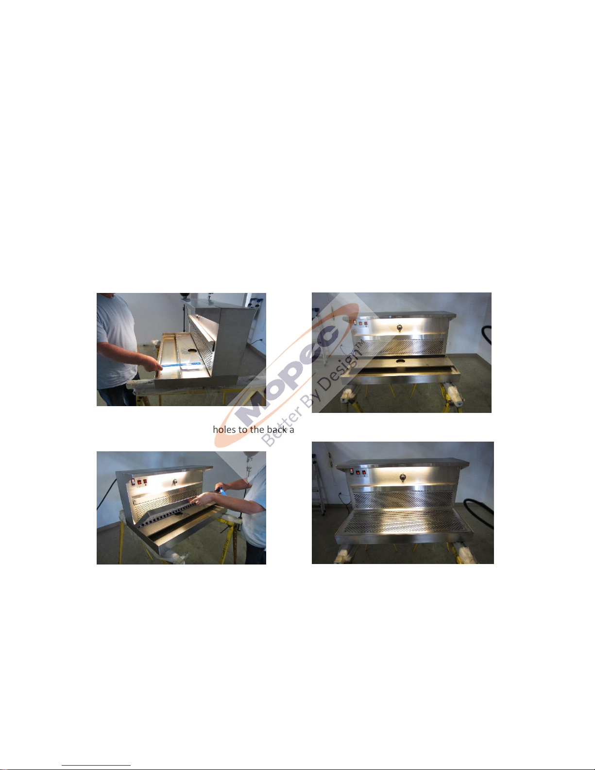
The ventilation diverter should be placed no more than 15CM (Approx 6” from the front/ Please see the photo below.
The grid plate must be installed with the holes to the back and the finger holes to the front as shown below
The next step is to open filter access door (it the unit is a recirculating air unit) by unlatching both side latches pivoting
the access door open and removing filters.
Each filter can be removed simply by pulling it toward you and out of the module. Both the activated charcoal filters
are wrapped in plastic and must be removed before installation. You may notice some loose charcoal particles due to
transportation which is normal.
Once the plastic is removed slide the filter in the slot and close the door.
** Caution ** These are general guidelines and installation is specific for each of the BF Series units. Professional
installation is recommended.
Page 7
P a g e | 7
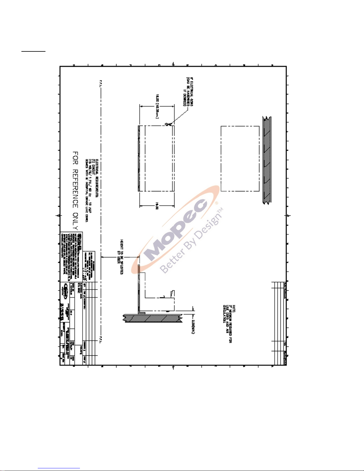
Rough In Drawings
BF400
Page 8
P a g e | 8
BF450
Page 9
P a g e | 9
BF500
Page 10
P a g e | 10
BF510
Page 11
P a g e | 11
BF550
Page 12

P a g e | 12
INTRODUCTION
The “BF Series of Down and Back Draft Workstations” is a group of compact grossing workstations that are
ideal for small surgical procedures. The “BF” family is comprised of the following models:
BF 400 is a compact Countertop Grossing Station utilizing. Recirculating Ventilation System and a
large lighted work area.
BF 450 is a compact Countertop Grossing Station utilizing In-house Ventilation System and a large
lighted work area.
BF 500 is a Freestanding Grossing Station utilizing. Recirculation Ventilation System, a Hand Spray
Rinse System and a large lighted work area.
BF 550 is a Freestanding Grossing Station utilizing In-house Ventilation System, a Hand Spray Rinse
System and a large lighted work area.
BF510 is a Portable Grossing Station with a Recirculation Ventilation System, a Hand Spray Rinse
System and a large lighted work area.
The BF400 and BF500 workstations are designed with a down and back draft ventilated work surface.
The design allows air to flow through the grid plate. The BF400 is designed with a catch pan to collect fluids if
necessary while the BF500 is freestanding with a built-in drain connection that fluids can flow directly into
the drain.
The BF400 is designed to fit onto a standard countertop. The BF500 is free standing complete with
drain connection. The BF Series air flow is achieved in one of two ways; the unit can be connected to the
ventilation system of the facility or with the built-in fans and filters.
The blower motor must be turned on with the red switch next to the fan speed control. The variable speed
fan is operated by turning the control to 100 and turning the knob to the desired speed. This allows the fan
to attain its full speed and then adjust to the requested speed.
Page 13
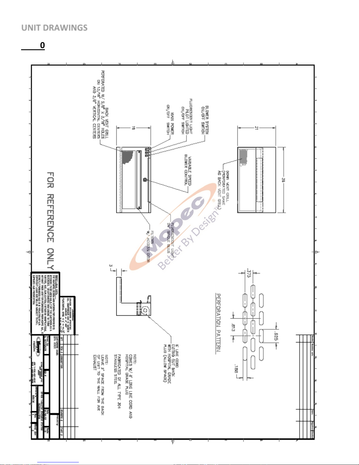
P a g e | 13
UNIT DRAWINGS
BF400
Page 14
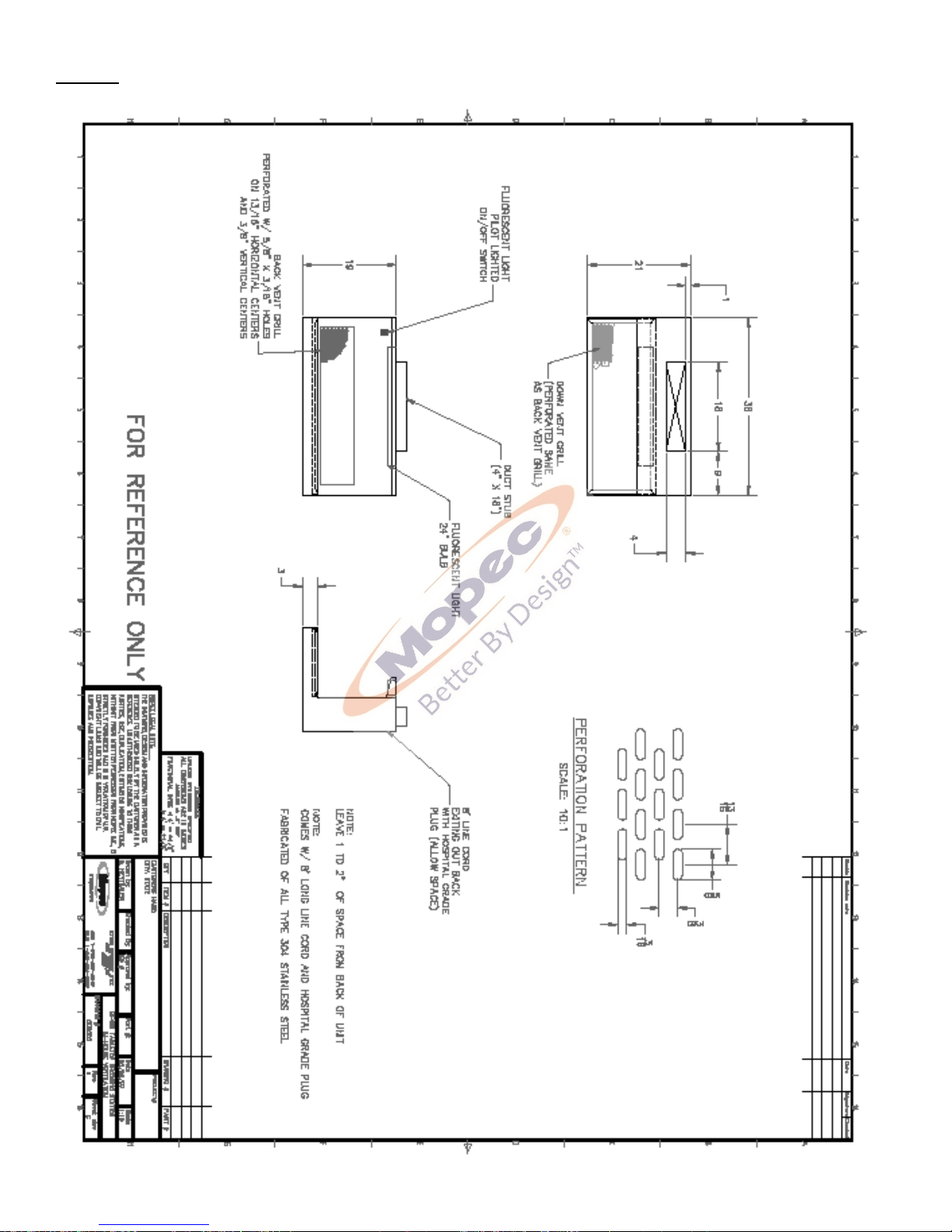
P a g e | 14
BF450
Page 15
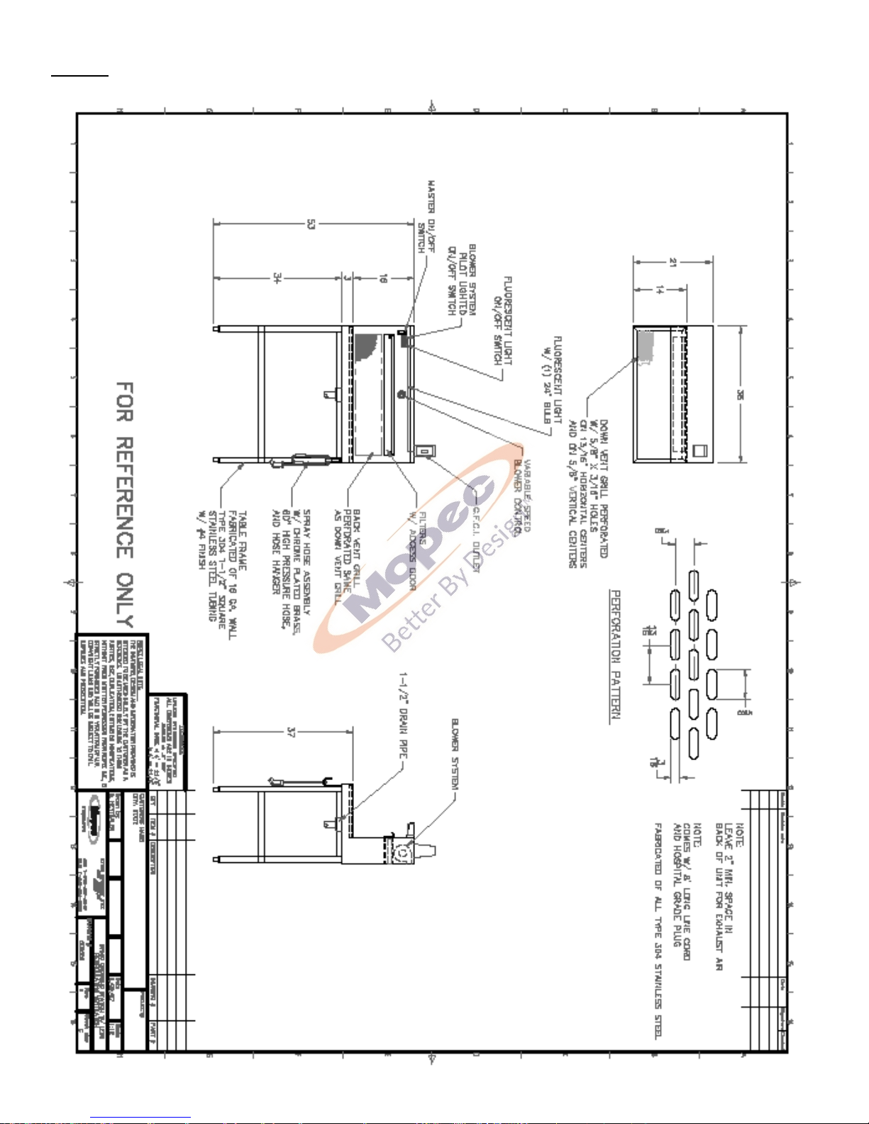
P a g e | 15
BF500
Page 16
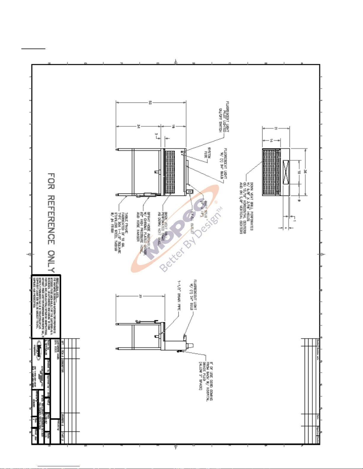
P a g e | 16
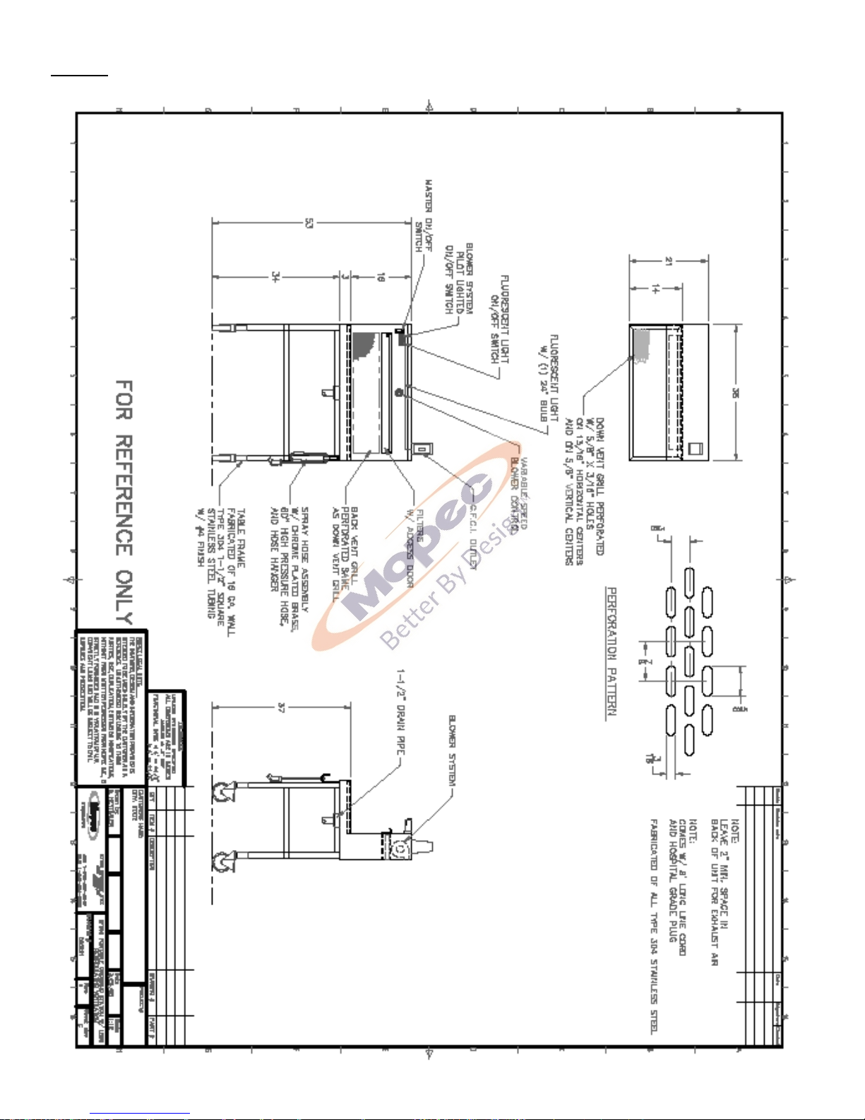
BF510
Page 17
P a g e | 17
BF550
Page 18
P a g e | 18
FEATURES
All units in the “BF” family consists of the following:
Work Grid: 18 Gauge, type 304 Stainless Steel with a # 4 Satin Finish
Housing: 18 Gauge, Type 304 Stainless Steel with a # 4 Satin Finish
Work Area: 13” x 34” (33 cm x 86 cm)
Electrical: 115 v / 1ph / 60 Hz Current Draw: 20 Amp maximum
Power: 8’ (274 cm) Hospital Grade Line Cord 115 v / 1ph / 60 Hz
Lights: 18” Standard Fluorescent Replacement Bulb with Pilot Lighted on/off Switch
All units have Perforated Back Vent Grill
Perforated Downdraft Grid Plate
Circuit Breaker Switch
Unique features by unit consist of the following:
BF400
Fan System: Dual Exhaust Blowers, 300 CFM. Both blower’s velocity is adjustable speed, controlled by a
rheostat.
Filters: 7” W x 14” L x 1” (183 cm x 35 cm x 2.5 cm) Front Access
(Fine Particle Activated Charcoal Media or Potassium Permanganate)
Storage Shelf: Top shelf is 12” W x 35” L (30 cm x 91 cm)
BF500
Fan System: Dual Exhaust Blowers, 300 CFM. Both blower’s velocity is adjustable speed, controlled by a
rheostat.
Filters: 7” W x 14” L x 1” (183 cm x 35 cm x 2.5 cm) Front Access
(Fine Particle Activated Charcoal Media or Potassium Permanganate)
Storage Shelf: Top shelf is 12” W x 35” L (30 cm x 91 cm)
Top Mounted water tight G.F.C.I. Outlet
Hand Spray: 60” (152 cm) high pressure hose Drain Pipe for easy hook-up
BF550
Storage Shelf: Top shelf is 12” W x 35” L (30 cm x 91 cm)
Top Mounted water tight G.F.C.I. Outlet
Hand Spray: 60” (152 cm) high pressure hose. Drain Pipe for easy hook-up
BF510
Fan System: Dual Exhaust Blowers, 300 CFM. One blower is constant
velocity and the other is adjustable speed, controlled by a rheostat.
Filters: 7” W x 14” L x 1” (183 cm x 35 cm x 2.5 cm) Front Access
(Fine Particle Activated Charcoal Media or Potassium Permanganate)
Storage Shelf: Top shelf is 12” W x 35” L (30 cm x 91 cm)
Top Mounted water tight G.F.C.I. Outlet
Hand Spray: 60” (152 cm) high pressure hose. Drain Pipe for easy
hook-up
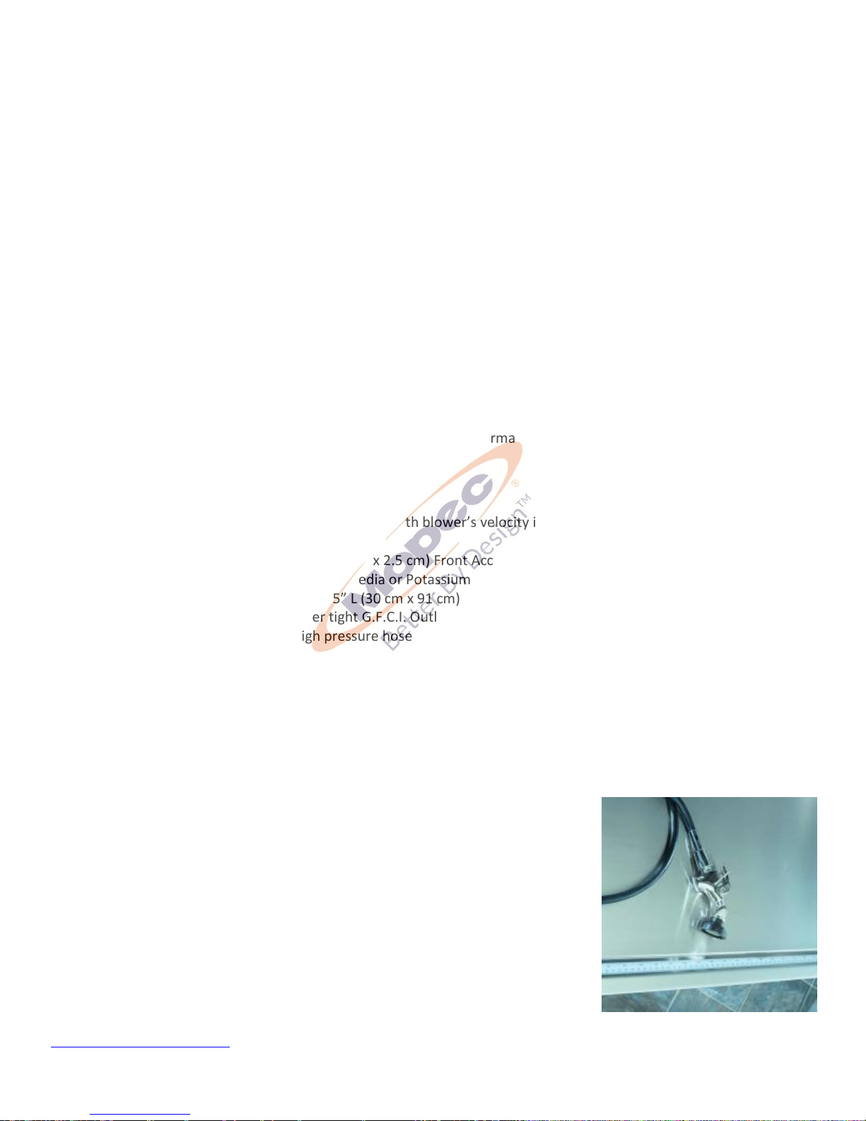
Chrome plated brass hand sprayer with soft spray & 60" Long high pressure hose for
easy and controlled rinsing of work surface. The water pressure is regulated by the
deck mounted valve. Press the lever on the spray head to utilize the spray rinse.
Hand Spray Rinse Video Link
Page 19

P a g e | 19
AIR HANDLING
BF Series Back and Down Draft Workstation Design Parameters:
The BF Series Workstations are designed with the basis of fulfilling one goal and that is to adequately ventilate the
work surface. An adverse effect of ventilation is noise that has been considered but does not govern the ultimate
design criteria. Our design criteria are the most stringent utilizing exerts as outlined from “Industrial Ventilation” by
Committee on Industrial Ventilation and Escape Velocity Parameters. Design data is unfortunately based on the table
as a completely flooded vat of formaldehyde. Ideal conditions in a grossing environment obviously do not warrant such
a large amount of formaldehyde, yet concentration levels are on a higher extreme regarding design data parameters
available. Therefore, assumptions are made regarding grossing practices and ultimately formaldehyde concentrations.
Two (2) blowers are supplied with the BF400, BF500 and BF510 are designed with an adjustable control to regulate the
speed and consequentially the airflow. The BF450 and BF550 workstations are in house ventilation and do not have
blowers or filters With all the above considered, below is a chart of actual ventilation parameters for MB Series
Grossing Workstations along with their respective definitions:
Identification Description Ventilation Volume
System Requirements
BF400 Down and Backdraft workstation Re-circulating 300 cfm
BF450 Down and Backdraft Workstation In-House 300 cfm
BF500 Down and Backdraft workstation Re-circulating 300 cfm
BF510 Down and Backdraft workstation Re-circulating 300 cfm
BF550 Down and Backdraft Workstation In-House 300 cfm
a Re-circulating (Self-contained exhaust Systems): This system is simply a self-contained exhaust system provide with
the Workstation. Air is ventilated through the exhaust grill and circulated through potassium permanganate filters and
exhausted out the back of the Grossing Workstation. The exhaust fans are internal and are provided.
The grill for the MB600 is 8” high at an angle of 60 Degrees and 48” Long with (994) 3/16” x 5/8” holes.
The vent grill is perforated with 3/16” x 5/8” slots on 13/16” x 3/8” staggered centers, yielding a 30% open area.
b Both specifications for Fan 1 and Fan 2 are “Free Air” cfm.
When connected to the building ventilation system, volumetric flow rates should be adjustable and be between 300
and 350 CFM (Cubic Feet per Minute. This variable will allow the user a means of adjusting the airflow to their comfort
level and work conditions. Calculations are based on 125 LFM (Linear Feet per Minute) face velocity through the grid
plates. It should be noted that the working environment is totally open therefore existing room conditions and air
currents have a serious effect on the efficiency of the ventilation.
The design parameters for the BF Series Workstations are suggested ventilation requirements and are based on
stringent ventilation requirements and ideal conditions. Personalized conditions and practices may warrant an increase
or decrease of the ventilation
GOOD PRACTICE WILL OPTIMIZE OUR PROTECTION:
1. Never block the ventilation grill.
2. Placing open containers as close to the exhaust grill as possible, yet never blocking the ventilation grill.
3. Grossing should be accomplished as close to the exhaust grill as possible.
4. Strategically locate the Grossing Station away from room air currents.
5. Practice complete rinsing of residual formaldehyde with hand held spray.
Although the Mopec Grossing Workstation can be the answer to formaldehyde exposure, Mopec cannot assume
responsibility of exposure since good laboratory practices and room conditions are beyond Mopec’s control.
Page 20
P a g e | 20
CLEANING AND MAINTENANCE
EVALUATING FILTERS FOR REPLACEMENT
The filters in your MB unit contain alumina pellets impregnated with potassium permanganate, KMnO4, which is a fast
oxidizer. Formaldehyde passing through the filter is converted to carbon dioxide and water. The filter’s life depends
entirely on the amount of formaldehyde fumes passing through the filter.
The pellets are bright purple when new and become dark brown when spent. Once the inner part of the pellet is
brown it is totally spent and must be replaced.
This chemistry is very effective and essentially removes all formaldehyde as long as there is active KMnO4 available.
The efficiency drops off as the filter media approaches its maximum capacity. The last 15-20% capacity will exhibit
some pass through of formaldehyde.
PROCEDURE - EVALUATING FILTERS FOR REPLACEMENT
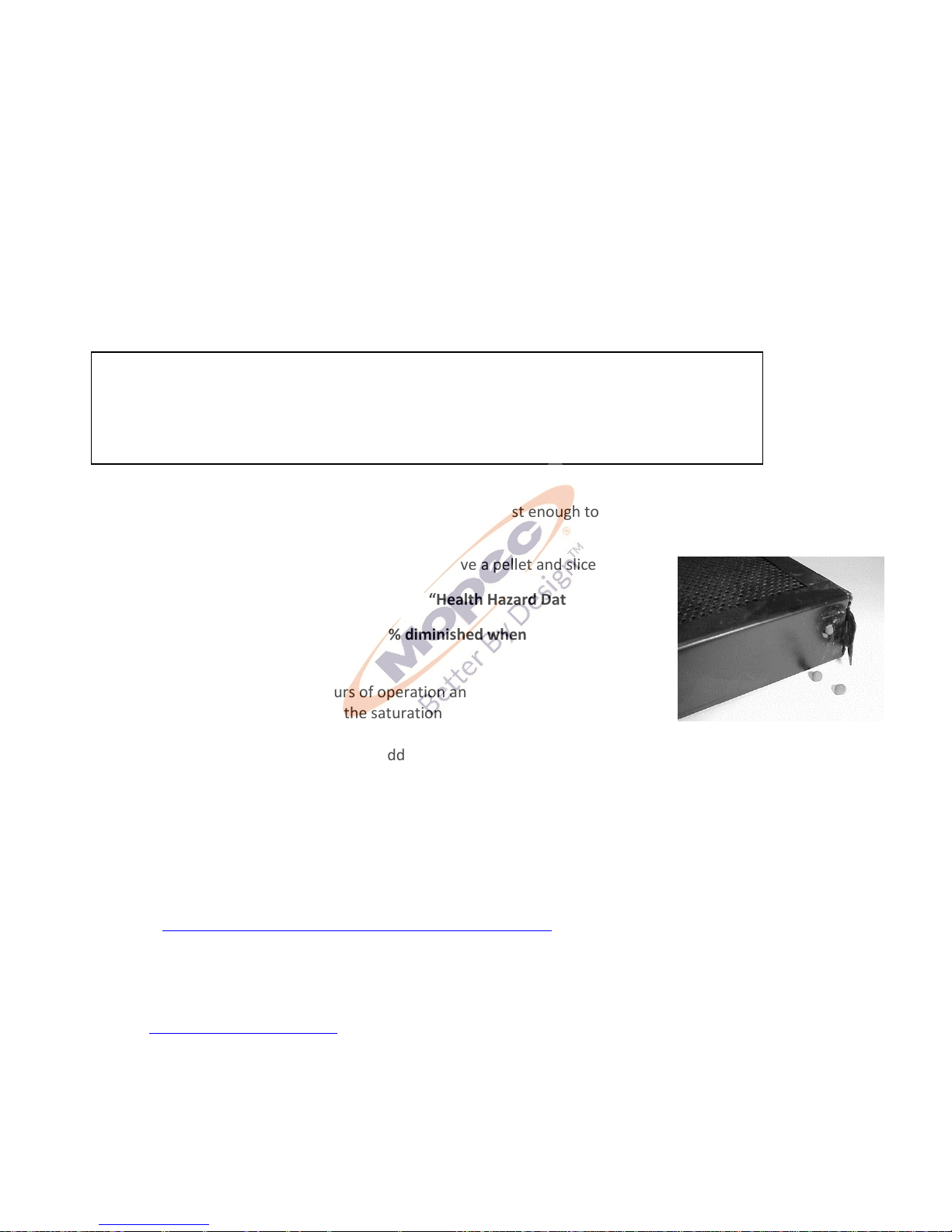
One side of the filter will have a small tab which can be opened just enough to allow one or two pellets to be removed.
(See photo)
To determine when the KMnO4 has been exhausted, remove a pellet and slice it in half.
Eye protection is recommended based on the above “Health Hazard Data”.
The usefulness of the filter is approximately 80% diminished when the purple color
first disappears from the core.
The filter saturation rate depends on hours of operation and fumes to be filtered.
Instructions on how to change and check the saturation of the filters
Place the sliced pellet(s) on a paper towel and add a few drops of water. The water running off the pellet(s) should be
initially purple and then turn a deep iodine color. If no purple coloration is present, the KMnO4 (Potassium
Permanganate) material is totally spent.
When the purple color first disappears from the core of the pellet as described above, the rate at which
formaldehyde is removed from the air stream is slowed considerably.
(See Summary on Following Page)
PROCEDURE – SUMMARY OF EVALUATING FILTERS FOR REPLACEMENT
From a practical standpoint, it may be desirable to perform the tests on the preceding page more frequently during
initial usage of the filters to determine when the purple first begins to disappear from the core of the sliced pellet.
Based on these early observations, the user can establish a Replacement Testing Cycle with occasional re-checks for
verification. Filter Evaluation Video Link
The filter saturation rate depends on hours of operation and fumes to be filtered. Instructions on how to change and
check the saturation of the filters are shown in the following links
Dispose of contaminated filters in accordance with your facility, state and federal procedures for hazardous materials
disposal. See the SDS for the chemicals exposed to the filters for directions.
Health Hazard Data - Alumina Permanganate Filter Media
Effects of Exposure – The filter media is non-toxic upon oral, skin, and inhalation exposure and is non-irritant of the
skin. Breathing of dust may cause sneezing. Skin may feel dry after contact. The filter media is an eye irritant.
Page 21

P a g e | 21
STAINLESS STEEL CARE AND MAINTENANCE
To maintain your stainless-steel product, follow these four steps:
1) Never, ever use wire brushes, Brillo, steel wool or abrasive cleansers (like Ajax or Comet). If something needs to
be aggressively cleaned only use a Scotch-brite pad or similar product and only scour with the "grain" of the stainless.
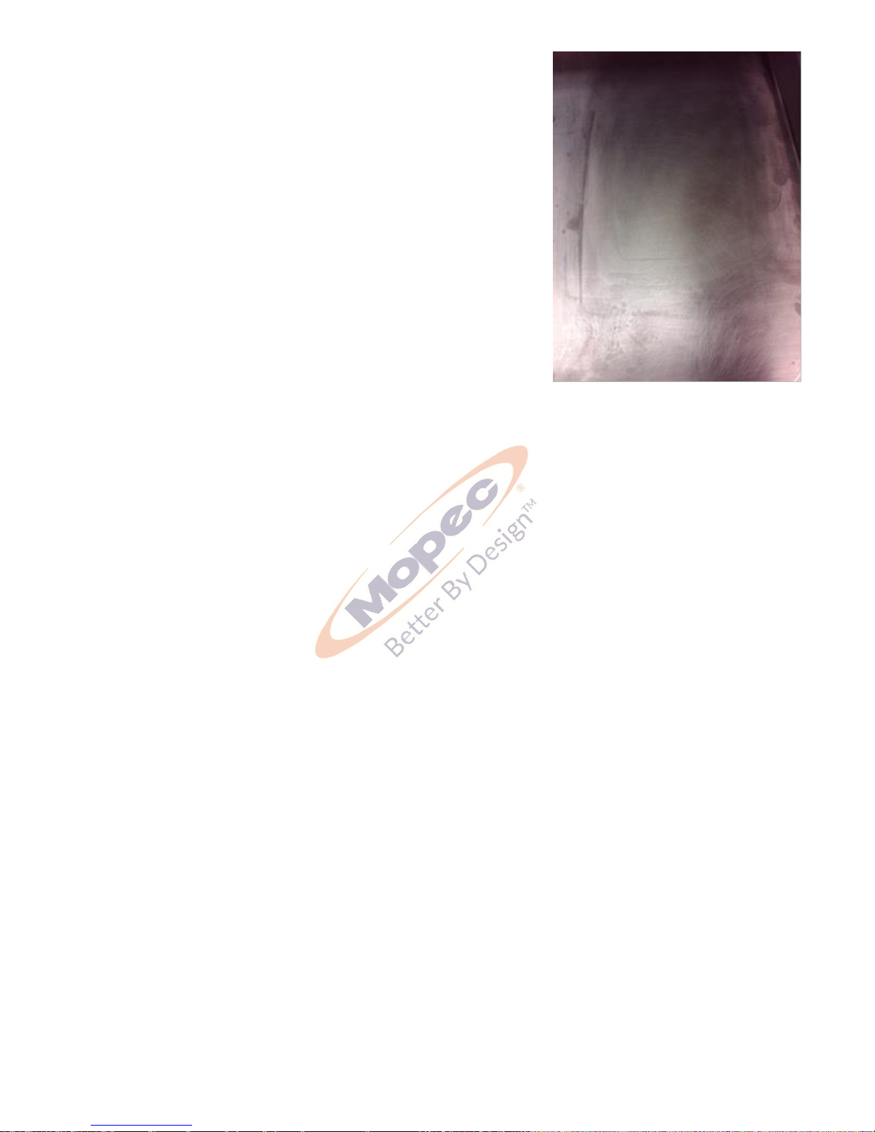
As an example, please reference the photo on page 2 of this document. A very abrasive product was used in an area on
the unit and that did not follow the grain of the stainless. The effects of this scratching may diminish over time with
proper care but the effects of this scouring are obvious. (The use of the Scotch-brite Pad following the grain over time
may help scratches such as this). Depending on the surface finish of your stainless steel, abrasive cleaners can cause
scratching. Duller finishes probably won’t show scratching as much as mirror or highly polished finishes. When in
doubt, test in a hidden spot, and work from the least risky type of cleaning, (i.e. water) to the heavy-duty stuff.
Do not use cleaners containing chlorine. While it may be second nature to bleach everything, stainless steel and
chlorine do not mix well. Do not use bleach when cleaning stainless steel. Do not allow bleach or bleach water to sit for
long periods. Bleach can eventually cause staining and pitting. Bleach stains are removed with stainless steel cleaning
polish.
2) Keep the surface clean of grime, tissue and particulates. This can be accomplished by using the "Water Hand Spray
Rinse" and use of cleaning products.
3) Rinse the surface after using disinfectant. In Pathology and other medical areas, the act of disinfecting is desired.
There are several ways to do this including using Mopec’s Bench Spray & Wipe Disinfectant. Labs use any number of
different products including 10% bleach or other disinfectant sprays and wipes. For the most part, each one of these
has high salt contents and lower PH levels to aid with disinfection. Most disinfectants must be followed up with a
water rinse to remove the salts that remain after these products dry. We advise to always follow up a disinfection
cleaning with a thorough rinse of water. We advise not to use diluted bleach, if you must; we stress the importance of
a thorough rinse of water after use. If not rinsed properly, these salts can become visible after the disinfectant dries.
They can appear with a whitish characteristic or contain light lines of white with a grainy feel when you wipe your hand
across the work surface. If these residues are not removed with a thorough water rinse and wipe down, they will
accumulate and eventually degrade the appearance and integrity of your stainless surface. Rust is a long-term
possibility if salts can remain on the work surfaces over time. Gritty, dirty water or residue from cleaning solutions left
on a stainless-steel surface can stain or damage the finish.
4) All stainless-steel products should be protected by a polish. As a prime example before any product leaves Mopec
it is coated with WD-40 as a protecting coating for the stainless. Mopec offers a Stainless-Steel Cleaner and Polish in
both wipe and spray. These Mopec products will not only deep clean your stainless but will also protect their finish
from chemical, low PH and salt and keep the finish looking like new.
Decal
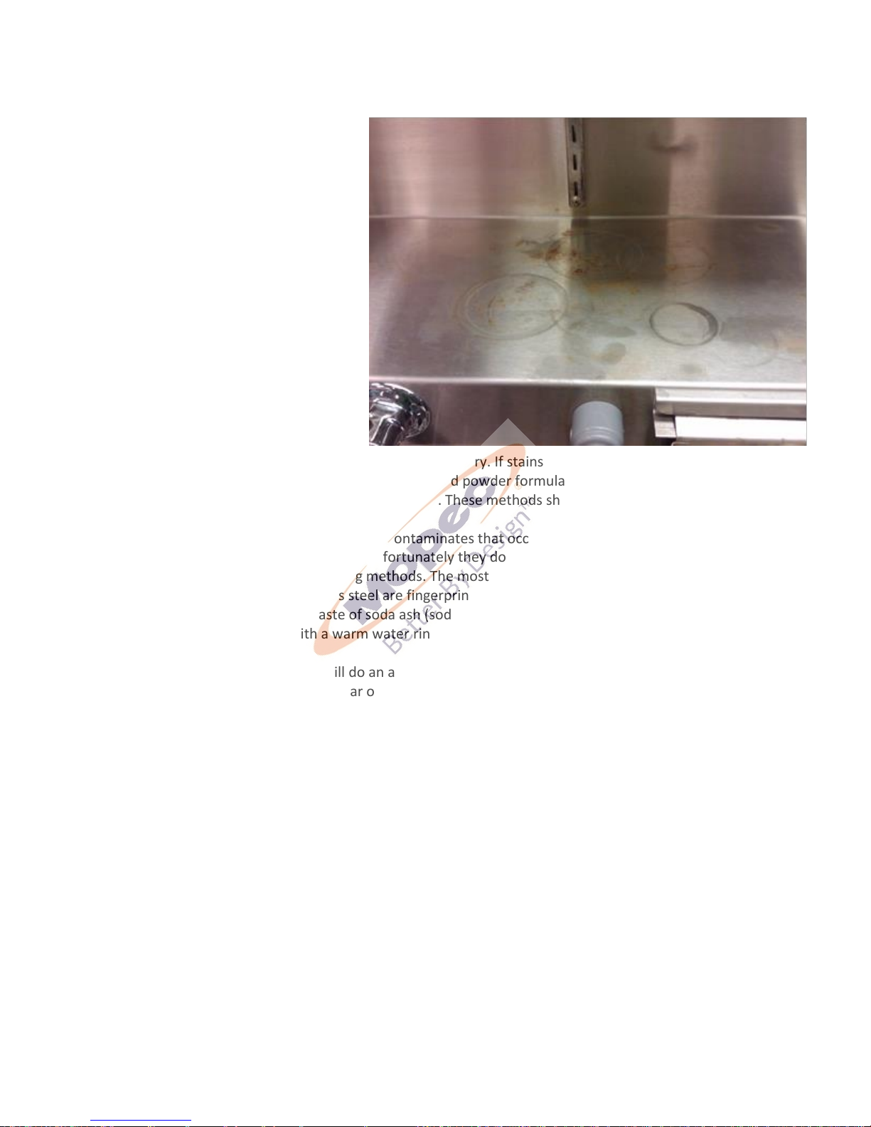
Mopec advises that if the technicians are not taking the proper precautions when using the Decal solution, the
possibility of two things will occur, a brown or rust ring where the Decal resides along with a milky white substance on
the surface. (As an example, reference the below photos to see the rust rings.) Decal is very harsh, even the fumes can
and will cause staining on stainless steel. One thing that you might want to consider doing is to place the Decal
container you currently use inside a plastic base that will help catch drips that might occur. Clean and rinse your
station after every use of Decal solution.
Rust
Rust can and will occur on stainless if it is not maintained properly. The most common cause of rust is from using metal
or stainless racks that are not made of 304 stainless. This is referred to as "transfer rust". Leaving of salts from cleaners
or disinfectants can and will lead to possible rust areas in the long term. Always rinse all disinfectants before they dry.
Decal solutions and even fumes are very aggressive and can cause rust if not cleaned up and used properly around
stainless. Formalin use has not been shown to cause rust in any way.
Page 22
P a g e | 22
Conclusions & Suggestions
We are confident and can assure you that if you institute the suggestions detailed above that your Mopec Grossing
station will look as it did the day it arrived.
Do not assume it's the cleaner. If you do have
some spotting or staining, and you've followed
all the suggestions, it may not be the cleaner.
Water, especially hard water, can leave
spotting and staining on stainless steel surfaces.
Hard water can leave mineral deposits,
resulting in whitish-colored spots and streaks.
Remove hard water stains with vinegar or with
stainless steel cleaning polish. Prevent hard
water stains by towel-drying after every wash.
Do not allow soaps and cleaners to dry on
surfaces. The chemicals in many soaps and
cleaners can cause staining. Never use
corrosive cleaners such as mineral spirits. Use
stainless steel cleaning polish and a nonabrasive scrub pad to remove dried cleaner
stains. Baking soda mixed with liquid dish soap
can make a good paste to gently rub on stains.
Be sure to rinse the stainless-steel surface thoroughly, and towel dry. If stains remain Mopec recommends trying a
stainless steel cleaner and polisher. Barkeeper's Friend is a good powder formula that can clean without scratching. Be
sure to follow the directions, rinse thoroughly, and towel dry. These methods should help remove any discoloration.
Fingerprints and Stains – The most common surface contaminates that occur from normal use are fingerprints and
mild stains. These usually affect only appearance so fortunately they do not influence corrosion resistance. They can
easily be removed by a variety of simple cleaning methods. The most troublesome marks to remove from the surface
of smooth polished or bright finished stainless steel are fingerprints; fortunately, they can be removed with a common
glass cleaner or by gently rubbing with a paste of soda ash (sodium carbonate) and water which would be applied with
a soft cloth. Again, it is best to follow with a warm water rinse.
Clean Water and Wipe – The method that will do an adequate job and is the simplest, safest and the least costly is the
best method. There is no surface coating to wear off stainless steels so the surface will thrive with frequent cleaning.
The first choice to clean mild stains and loose dirt and soil should always be a soft cloth and clean, warm water. Rinsing
with clean water and wiping the surface dry will finish the process and eliminate the possibility of water stains.
Solvent Cleaning – To remove oils, greases and fresh fingerprints that have not had time to oxidize or decompose, use
a solvent that does not contain chlorine. There are many organic cleaners on the market today that optimize safety
attributes and clean ability. Spray or vapor methods or by wiping with clothes containing solvents can also clean
surfaces. The wiping technique will sometimes leave the surface streaked.
Scratch Repair
A surface scratch can be repaired using the following technique. Completely removing the scratch will depend on how
severe it is. Use 120 grit emery cloth or paper and firm pressure to sand the scratch. Sanding must always go in the
direction of the grain. Sand in a perfectly straight line, avoiding the natural tendency to sand in an arc. Sand the surface
until the scratch is gone. Polish using a very fine grade of 3M scotch-brite pads. Use the same motions as with sanding.
Polish the surface until the original finish is restored.
For stubborn spots, stains, light discoloration, water marking or light rust staining use a mild, non-scratching cream or
polish. Apply with soft cloth or soft sponge and rinse off residues with clean water and dry. Avoid cleaning pastes with
abrasive additions. Suitable cream cleansers are available with soft calcium carbonate additions, or with the addition
of citric acid. Do not use chloride or acidic solutions Nylon abrasive pads should be adequate for dealing with most
Page 23
P a g e | 23
deposits (DO NOT USE STEEL WOOL OR BRILLO PADS). If a more severe
treatment is needed to mask coarse scratches or physical damage on a
surface, use the finest abrasive medium consistent with covering the
damage marks. With directional brushed and polished finishes, align and
blend the new "scratch pattern" with the original finish, checking that the
resulting finish is aesthetically acceptable. Silicon carbide media may be
used, especially for the final stages of finishing. Avoid using hard objects
such as knife blades and certain abrasive/souring agents as it is possible to
introduce surface scuffs and scratches. Scratching is particularly noticeable
on sink drainer areas. These are usually superficial and can be removed with
proprietary stainless steel cleaners or, alternatively, with a car paint
restorer, such as 'T-cut'. Rust marks or staining on stainless steels is unlikely
to be the result of corrosion to the stainless steel itself (similar marks may
also be found on porcelain and plastic sinks). These marks are likely to result
from small particles of carbon steel from wire wool.
Page 24

P a g e | 24
USER PARTS
Replacement parts are available from Mopec They can be ordered by contacting Mopec at 800-362-8491.
POTASSIUM PERMANGANATE FILTER BF007 Dimensions: 14" (35cm) L x 7" (17cm) W x 1" (2.54cm) H
ACTIVATED CARBON FILTERS BF008 Dimensions: 14" (35cm) L x 7" (17cm) W x 1" (2.54cm) H
Page 25

P a g e | 25
PREVENTITIVE MAINTENANCE CHECKS
Procedure:
1. Visually check the exterior of equipment for any signs of damage.
2. Visually check the condition of the power cord and plug(s) for cracks, cuts, bare or broken wires and signs of
excessive heat (discoloration).
3. Visually inspect electronics for signs of damage and/or overheating.
4. Ensure all the receptacles and covers are operating properly (testing GFCI).
5. Verify correct operation of unit including all controls, buttons, displays and indicators when applicable.
6. View under the leg frame to ensure no leaks, dry rotted hoses, or electrical issues under the table.
7. Check all water fixtures.
8. Clean exterior of unit.
9. Complete paper work of inspection and file in appropriate file for future reference. Complete and affix an
inspection sticker, when applicable.
10. Return the unit to service.
Page 26

P a g e | 26
WARRANTY CERTIFICATE
LIMITED WARRANTY
Products manufactured by Mopec will be free from defects in material and workmanship and conform to Mopec's
description or specifications. If a warranty claim is made within one (1) year from the earlier if the date of
acceptance/first beneficial use, the defective or nonconforming Product or Part thereof will be repaired or (at
Mopec's option) replaced free of charge, FCA Mopec's dock. All warranty claims must be in writing and received
by Mopec within the warranty period. The warranty is not transferable (other than to customers of Mopec’s
authorized Distributors), and will not apply unless the Equipment has been properly installed, maintained and
operated in accordance with all instructions; and does not apply to defects, nonconformities or other failure due
to Equipment misuse, abuse, modifications, or other causes outside Mopec‘s control. If a warranty claim is made
in writing within the warranty period, the defective or nonconforming Equipment (or Part thereof) will be repaired
or (at Mopec‘s option) replaced free of charge, FCA Mopec‘s dock.
THERE ARE NO WARRANTIES WHICH EXTEND BEYOND THE DESCRIPTION ON THE
FACE HEREOF. THE WARRANTY AS SET FORTH HEREIN IS IN LIEU OF ALL OTHER
WARRANTIES, EXPRESS OR IMPLIED, INCLUDING ANY IMPLIED WARRANTY OF
MERCHANTABILITY OR FITNESS FOR A PARTICULAR PURPOSE.
To the extent that Mopec is acting as a supplier of Products manufactured by a third party, the Products will be
warranted only to the extent that they are warranted by their manufacturers and Buyer (or its customer) agrees to
look solely to the Product manufacturer for all warranty claims.
MOPEC, 21750 COOLIDGE HIGHWAY, OAK PARK, MI 48237
Page 27
P a g e | 27
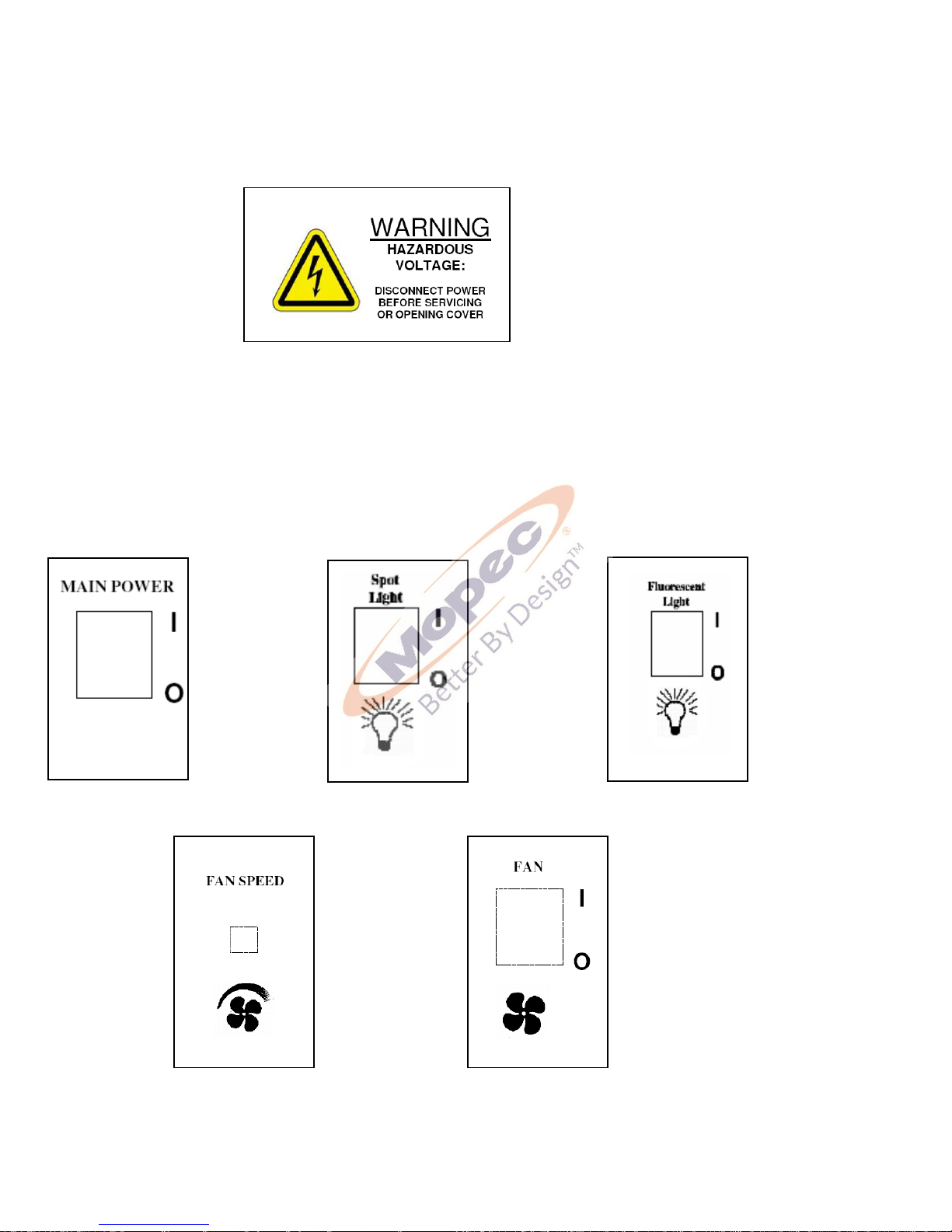
SAFETY LABELS
BEFORE SERVICING THE UNIT LOOK FOR AND HEED THE FOLLOWING LABEL
Symbols that may be found on the Equipment
Page 28

P a g e | 28
TROUBLE SHOOTING
Problem Possible Solution
My Unit does not turn on Assure your facility circuit breaker has not been
tripped.
Assure the G.F.C.I. has not been tripped (off) –
Reset to on.
y hand spray does not work Assure the water valve from your facility is on.
Assure the concealed shut off valves to the
hand spray are on.
Assure hose is not kinked.
My lights do not work Assure your facility circuit breaker has not been
tripped.
Assure unit is plugged in.
Assure the G.F.C.I. has not been tripped (off) –
Reset to on.
Assure Master Switch is turned on – Switch is lighted when on.
Assure light switch is on.
My unit does not remove odors Assure your facility circuit breaker has not been
tripped.
Assure unit is plugged in.
Assure the G.F.C.I. has not been tripped (off) –
Reset to on.
Assure Master Switch is turned on – Switch is lighted when on.
Assure Fan Switch is on.
Turn up fan speed.
Assure plastic wrap is removed from filters.
Assure filters are in place.
Assure filters are not clogged or contaminated
Page 29
P a g e | 29
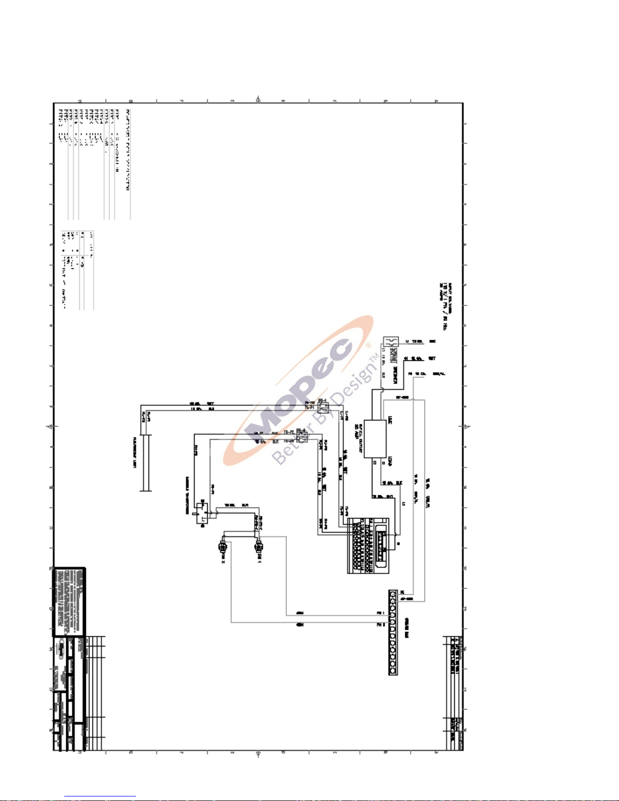
ELECTRICAL DIAGRAM
Page 30

P a g e | 30
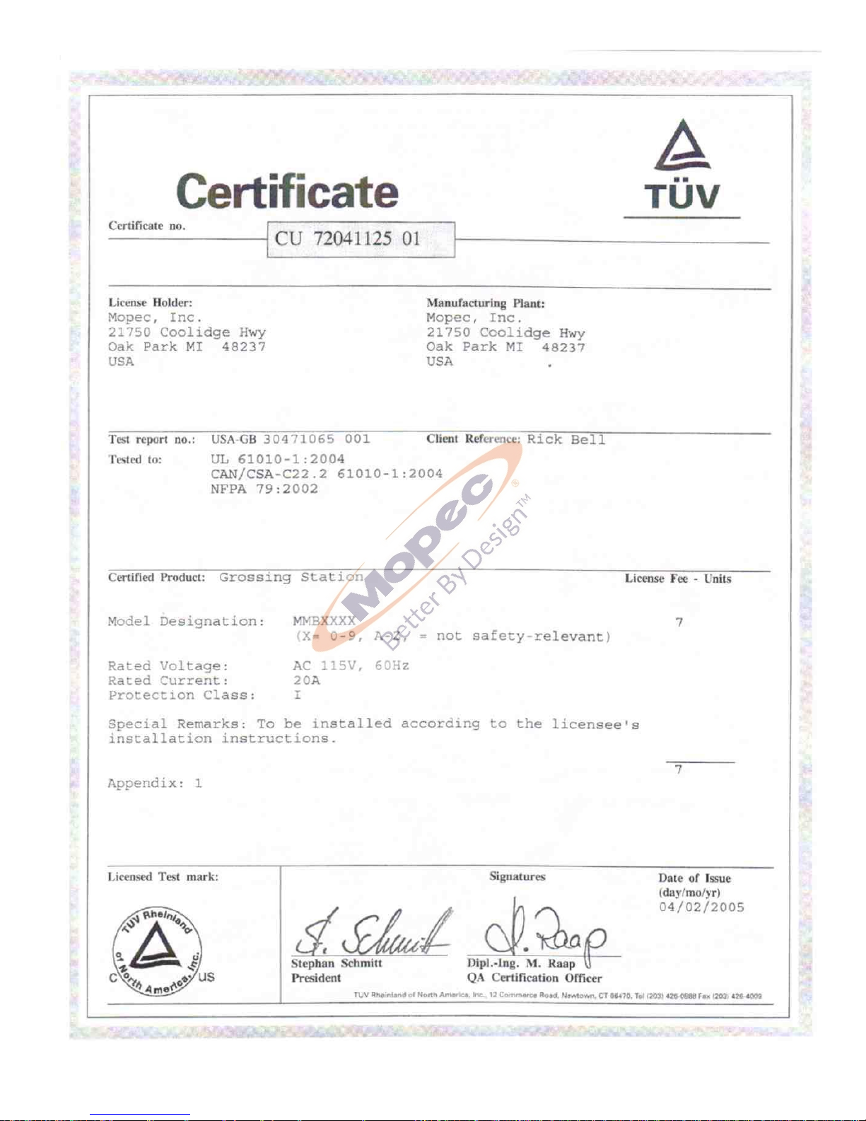
CERTIFICATES
Page 31
P a g e | 31
Page 32

P a g e | 32
2015 Mopec all rights reserved
 Loading...