

Mopec BF400, BF450, BF500, BF550, BF510 User Manual
USER MANUAL
www.mopec.com
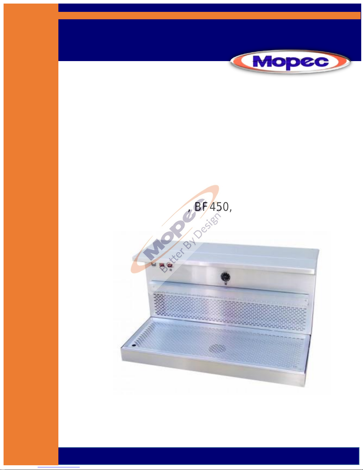
BF Series
Down/Back Draft Workstations
BF400, BF450, BF500, BF510, BF550
Rev 10-28-16 ©
P a g e | 2

P a g e | 3
TABLE OF CONTENTS
UNPACKAGING YOUR PRODUCT..…………………………………………………4
INSTALLATION………..…………………………………………………………….……..5
PRODUCT DRAWINGS
BF400 ROUGH IN……………………………………………………………..7
BF450 ROUGH IN……………………………………………………………..8
BF500 ROUGH IN (w Optional Leg Frame)..……………………..9
BF510 ROUGH IN…………………………………………………..………..10
BF550 ROUGH IN ………………………………………………..………….11
INTRODUCTION ……………………………………………………..…………………..12
PRODUCT DRAWINGS
BF400 …………………………………………………….……………………..13
BF450 …………………………………………………….……………………..14
BF500 …………………………… ……….…………….………………………15
BF510 ……………………………………………………………………………16
BF550 ……………………………………………………………………………17
FEATURES………………………………………………………………………………….18
AIR HANDLING………………………………………………..………………………..19
CLEANING AND MAINTENANCE
Filter information and evaluation………….……………..……….20
Stainless Steel Care and Maintenance………………………......21
Parts……………………………………………………..…………………..….24
Preventive Maintenance……………………….………………..…….25
WARRANTY……………………………………………………….………………..…….26
SAFETY LABELS……………………………………………………..…………..………27
TROUBLE SHOOTING GUIDE…………………………………………………..….28
ELECTRICAL DIAGRAM………………………………………….……………..…...29
CERTIFICATES……………………………………………………….……………..……30

P a g e | 4
UNPACKING
1) Carefully inspect the exterior of the shipping container before opening. If the crate is damaged and the
product has sustained damage, then immediately contact Mopec and the freight carrier. Never discard the
shipping container even if it is damaged beyond recognition.
2) Have the delivery driver note any suspected damage on the Bill of Lading and sign it. Mopec will help assist in
filing a claim for product repair and/or replacement.
3) Carefully open the containers and inspect the equipment for concealed damage. If visible damage is noticed
(i.e. broken welds, dented stainless, scratches, etc.) follow through as noted above. Do not discard the
shipping material. They are important in settling claims.
CAUTION: There are loose components in the packaging of your product. Be very careful in examining the
packaging material as it may contain installation parts and/or product components.
INSPECTION
1) After carefully unpacking your Mopec workstation please inspect the items in the list below prior to installing
the unit. The workstation should be thoroughly checked for loose screws, defects, or damage that may have
occurred during shipping or packaging.

P a g e | 5
INSTALLATION
BF Series Down and Back Draft Workstation Installation Instructions
Locate package of smaller items (dissection board, tissue boxes, or filters)
When removing from the shipping platform, be careful if the unit has a foot pedal. The unit should be removed from
the shipping platform as to not cause damage to the copper plumbing attached to the foot pedal
Leveling and Setting Unit in Place
The unit should be off the floor and resting on the leveling pads. The unit should be leveled to ensure proper drainage.
This allows water to evaporate or dry in case of a leak without getting trapped by the base of the unit Ensure there is a
Minimum of 6.5” from the wall to the back of the unit. This allows for elevating units to move freely without any
obstructions to the wall.
Utility Connections
The only connections necessary are the Electric, Cold and Hot water supply, the drain connection and the HVAC
connections if in house ventilation. The unit is already pre-wired and plumbed for the options ordered.
Electrical Connection
All electrical, water and ventilation stubs should be prepared in accordance with our rough-in dimensions shown on
rough in diagram from your approval process.
The electrical service provided for the MB600 must include:
1) A switch or circuit breaker for each circuit to which the wiring harnesses from the workstation will be
connected.
Each BF Series Workstation has a eight-foot line cord with a hospital grade plug. It is possible to order with a 3 foot
whip to permanently hard wire the unit to the electrical connection. The whip leads are labeled L1 and C1 for the unit
electrical options such as lights and fans if a recirculation unit.
There are three wires:
Black Labeled as L1
White Labeled as C1
Green w Yellow Stripe Ground
Flexible water tight conduit and connections are the preferred conduit and is not provided with the unit. This is due to
an unknown length needed and variances possible in the rough in process.
Drain Connection
The BF500, BF510 and BF550 workstations are equipped with 1.5” Diameter drain and connections. DO NOT modify
the drain line or connections without contacting MOPEC first. The Units are built in accordance with the rough in
drawings specific to the unit. The height is per the rough in drawings provided at the time of the order.
Water Supply Connection
The water supply connections are ½” DIA copper pipe. The unit has been cleared of water and debris during the
manufacturing and testing of the unit. The rough in drawing for the unit suggests a 1/4 turn valve to be connected to
the wall. This is to allow the water to be localized and disconnected should the need arise to work on plumbing in the
future. Before connecting the unit to the facility water supply, check the lines in the facility for debris by flushing the
lines for a moment. After the connections are made remove the aerator from the faucet and turn the water on and
open the faucet and other water options after the faucet to allow any debris to evacuate the system. This is the time
to look for leaks or other plumbing issues. The plumbing is tested for leaks and function at the facility and is put under
pressure for 45 minutes to check for leaks. However, the plumbing is hard copper and soldier connections. During
transport a unit may experience a failed soldier joint. Contact MOPEC immediately if there is a leak.
P a g e | 6
Ventilation Connection
Ventilation is one of two types for the BF Workstations; In House Ventilation or Recirculation. For in house the unit is
connected to the facility ventilation system via duct work.
In House
BF450 the connection is a 4” x 18” rectangular stub on the top back of your unit. The duct work is not provided by
Mopec unless specifically ordered.
MB550 the connection is a 4” x 18” rectangular stub on the top back of your unit. The duct work is not provided by
Mopec unless specifically ordered.
Recirculation
BF400, BF500 and BF510 the filters will need to be installed. You should have a minimum of 2 inches or more behind
the workstation for the filtered air to discharge. Air flow is generated by multiple fans in the recirculation models. They
are controlled by a rheostat to control volume/speed.
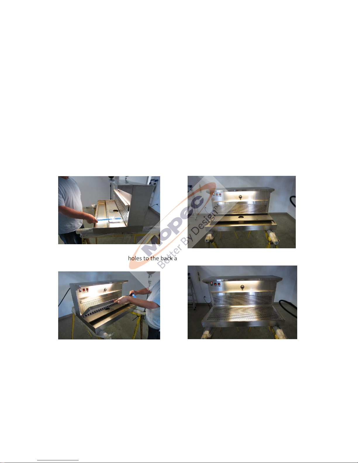
The ventilation diverter should be placed no more than 15CM (Approx 6” from the front/ Please see the photo below.
The grid plate must be installed with the holes to the back and the finger holes to the front as shown below
The next step is to open filter access door (it the unit is a recirculating air unit) by unlatching both side latches pivoting
the access door open and removing filters.
Each filter can be removed simply by pulling it toward you and out of the module. Both the activated charcoal filters
are wrapped in plastic and must be removed before installation. You may notice some loose charcoal particles due to
transportation which is normal.
Once the plastic is removed slide the filter in the slot and close the door.
** Caution ** These are general guidelines and installation is specific for each of the BF Series units. Professional
installation is recommended.
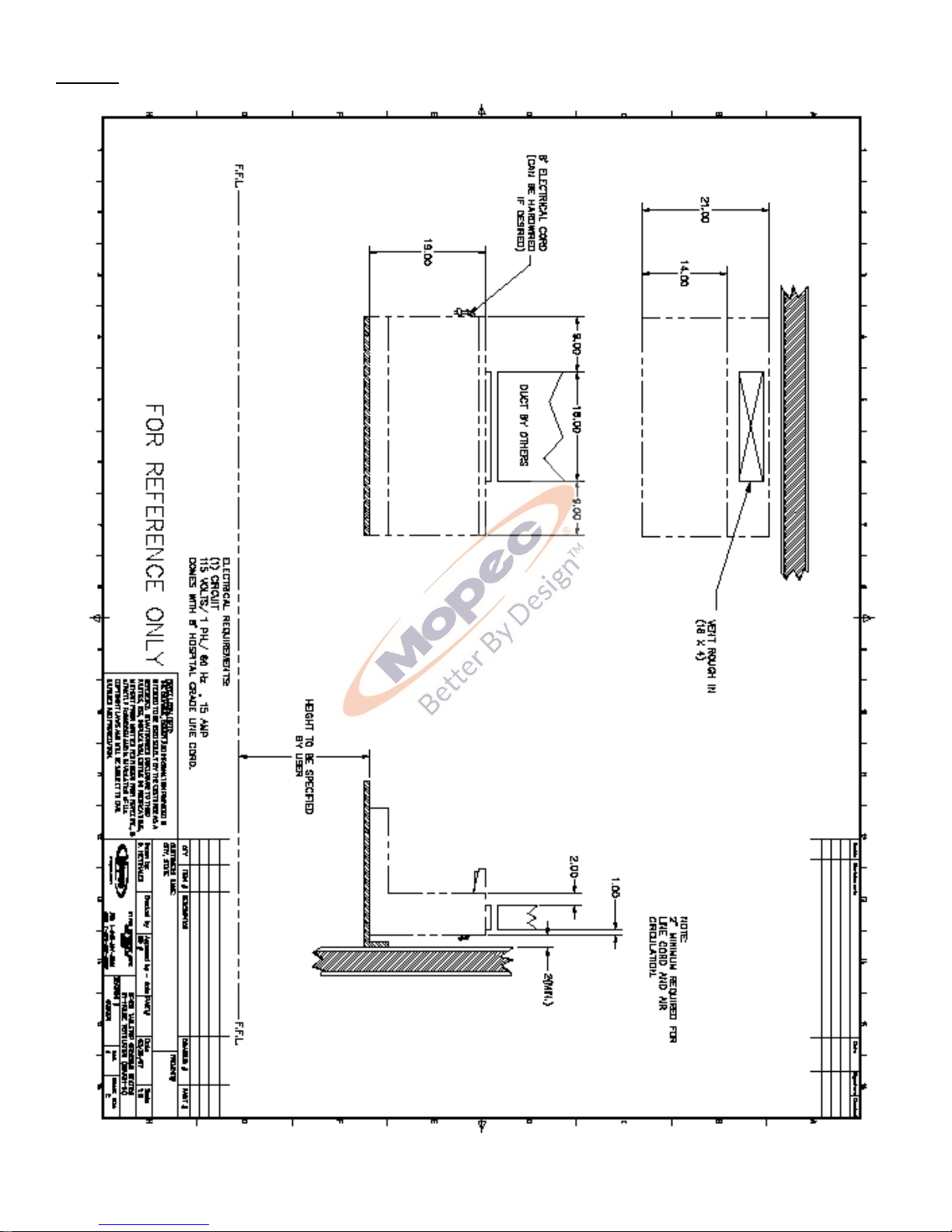
P a g e | 7
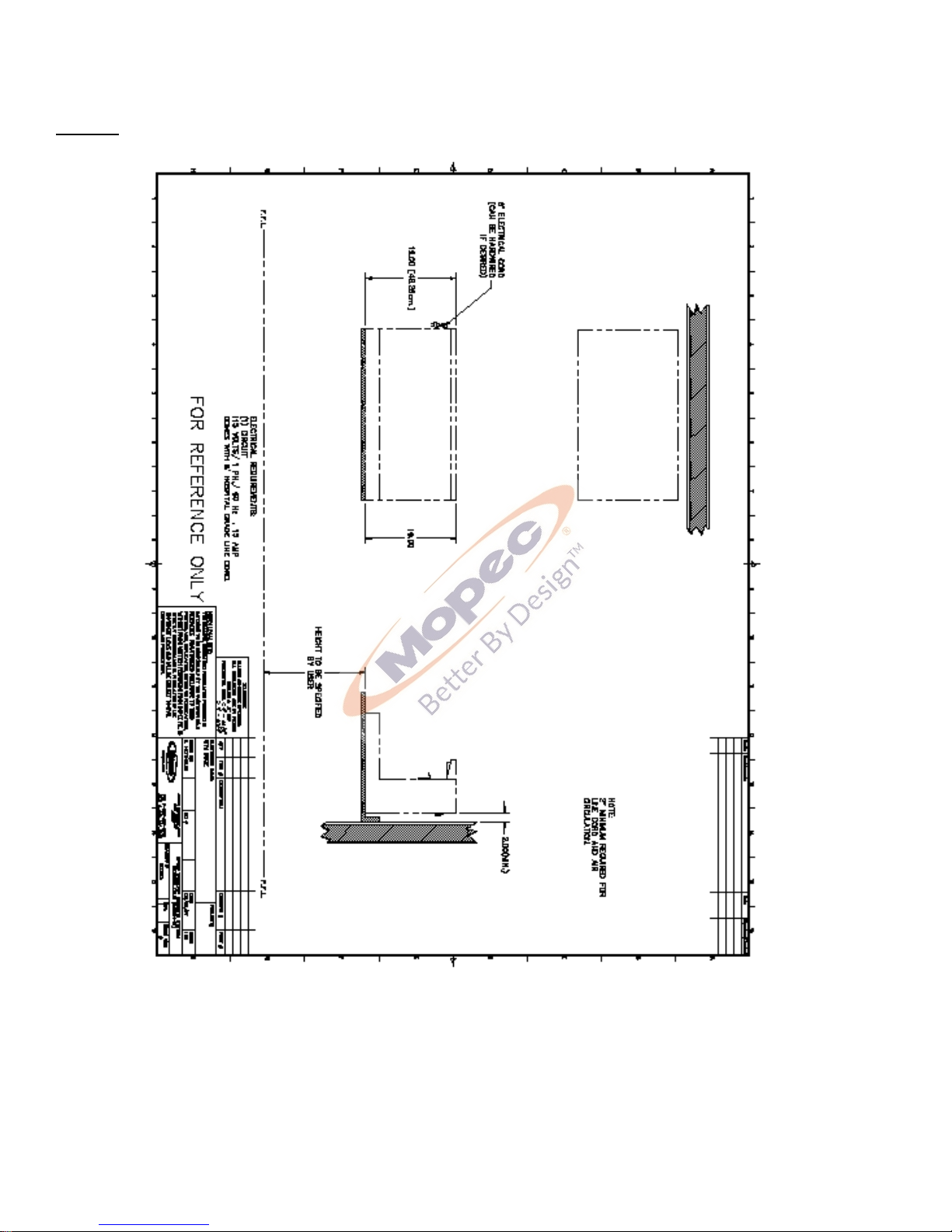
Rough In Drawings
BF400
P a g e | 8
BF450
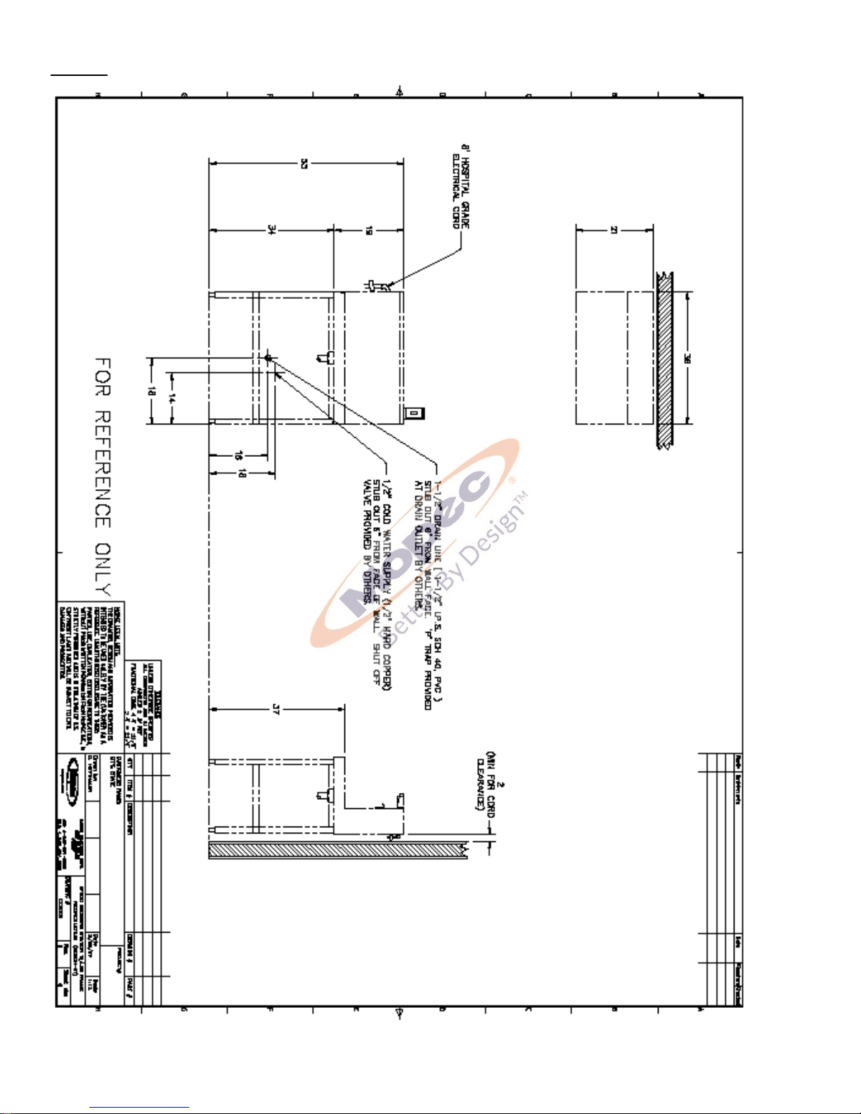
P a g e | 9
BF500
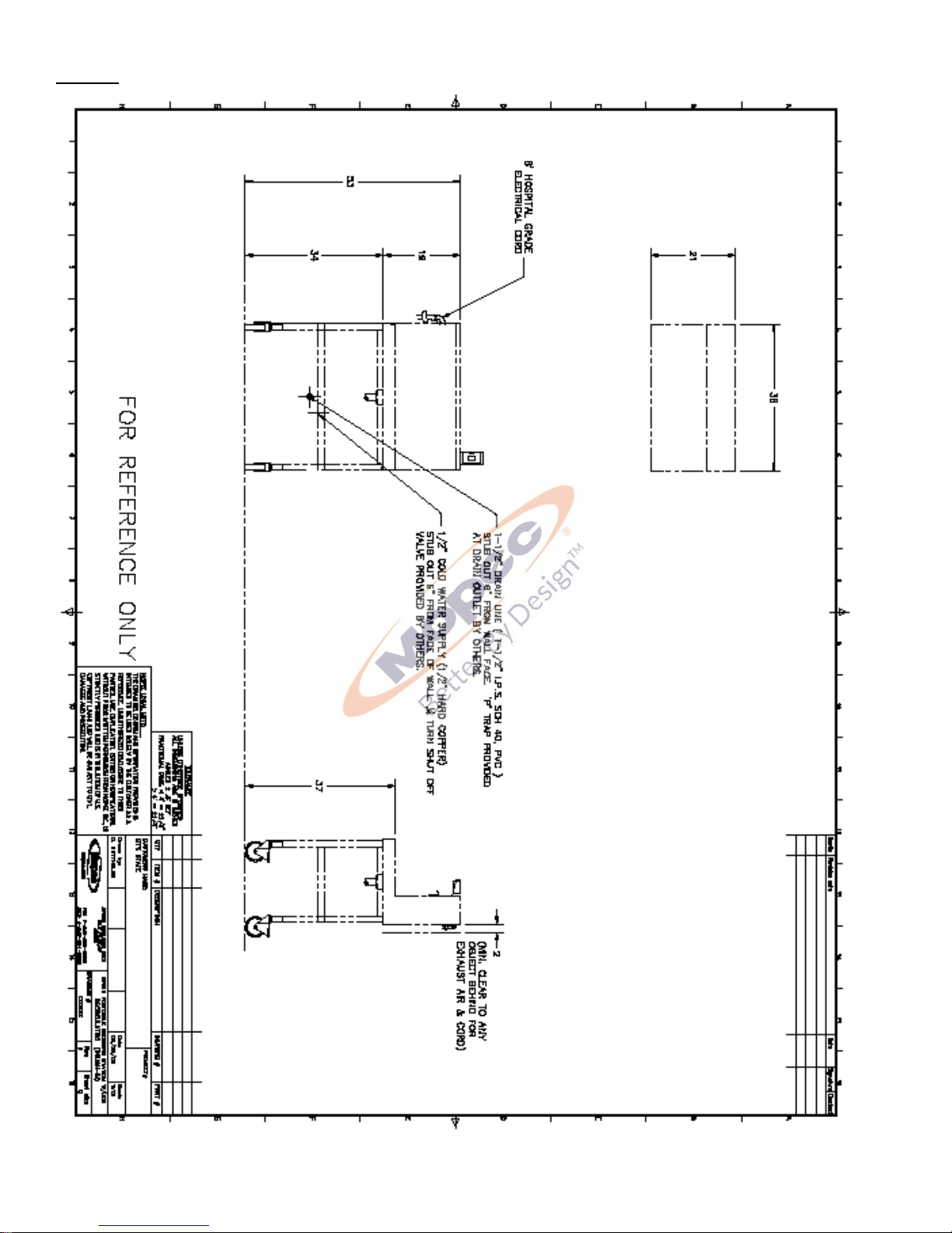
P a g e | 10
BF510
 Loading...