

Page 1
01-12-2004 1 of 20 K6858681
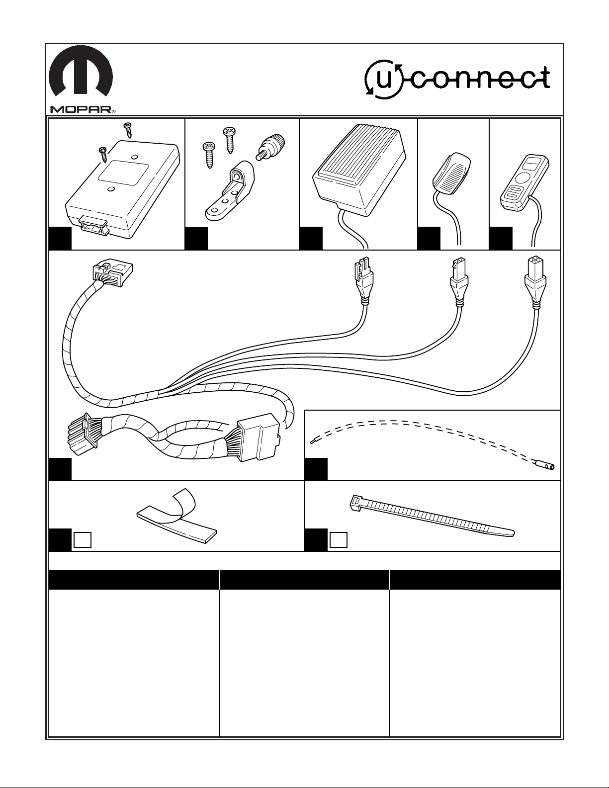
D
C
B
A
3x
I
3x
H
F
PT CRUISER . . . . . . . . . .6
300M . . . . . . . . . . . . . . . .7
CONCORDE . . . . . . . . . . .7
SEBRING SEDAN . . . . . .8
TOWN & COUNTRY . . . . .9
PACIFICA . . . . . . . . . . . .10
300C . . . . . . . . . . . . .11,12
MAGNUM . . . . . . . . . .11,12
NEON . . . . . . . . . . . . . . .13
INTREPID . . . . . . . . . . . . .7
STRATUS . . . . . . . . . . . . .8
CARAVAN . . . . . . . . . . . . .9
DURANGO/DAKOTA . . .14
2004 DURANGO . . . .15,16
RAM . . . . . . . . . . . . . . . .17
LIBERTY . . . . . . . . . . . . .18
GRAND CHEROKEE . . .19
E
CHRYSLER DODGE JEEP
G
# 04720928
Page 2
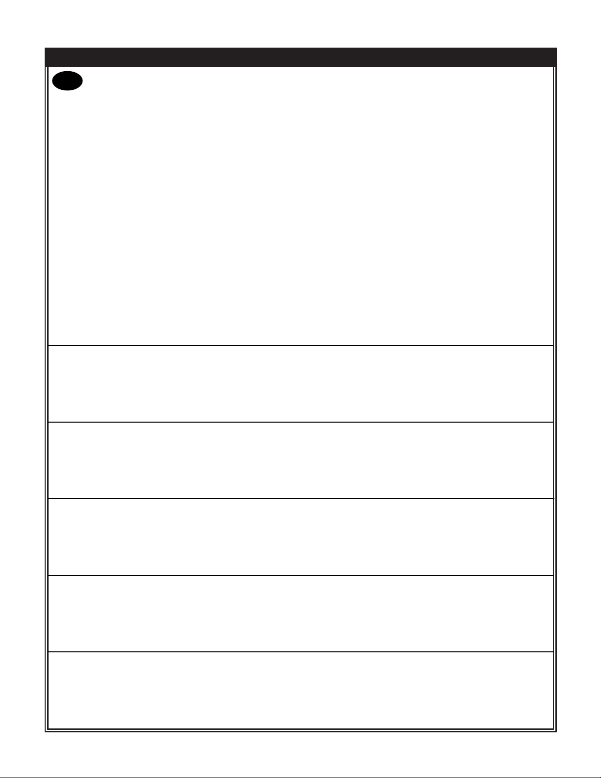
IMPORTANT NOTES
■ Disconnect and isolate negative battery cable.
■ Disconnect and remove overhead console or dome lamp, if equipped.
■ Remove left (driver’s side) A-pillar trim panel and left I\P access panel.
■ Remove I/P center cluster bezel. Disconnect and remove radio.
■ Remove knee blocker panel(s).
■ Install kit components as described in notes and as shown in illustrations. Ensure that all vehicle mounting
surfaces are clean.
■ Route Item F 22-way connectors and Item E cable connector up into the I/P at the knee blocker opening,
and out of the radio opening. Keep away from sharp edges, heat sources, or moving parts.
■ 2002-2004 Vehicles: Plug Item F 22-way connectors into radio and radio connector.
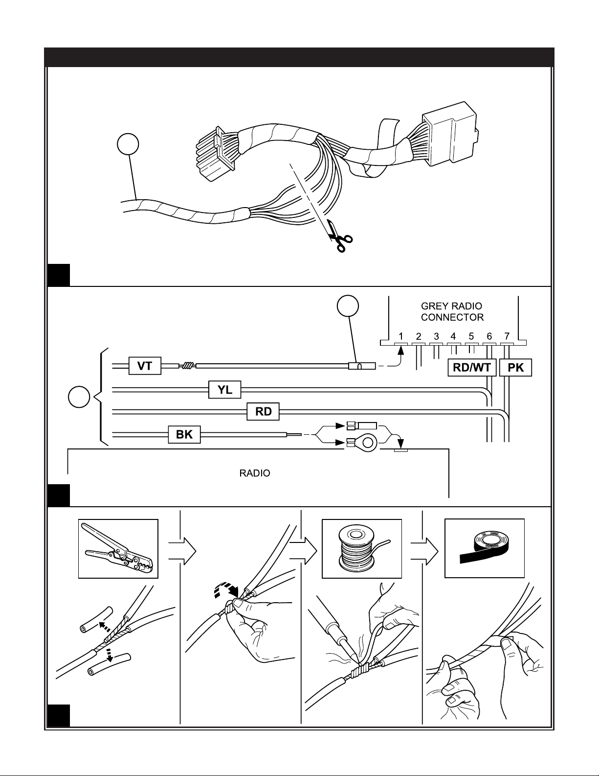
1990-2001 Vehicles: Follow procedure shown on page 5. Securely crimp a ground eyelet or a blade
terminal to the black wire.
■ Make electrical connections to items A, C, D, and E.
■ Loop-up slack in harness and cables. Apply tie straps and stow away neatly. Do not kink or tightly coil the
cables.
■ Re-install vehicle components and trim panels, ensuring that cables are not pinched under them.
■ Perform a functional check of the system by following the steps shown on page 20 of this document.
01-12-2004 2 of 20 K6858681
GB
ITEM A:
Place supplied 2-way tape to underside of module. Ensure tape contacts to vehicle mounting surfaces. Install
tie straps and mounting screws if needed.
ITEM B:
Measure for bracket mounting holes as shown in illustrations. Using the bracket as a template, drill two 1/8"
holes. Install bracket with supplied screws.
ITEM C:
Install speaker to mounting bracket. Position speaker as shown in illustrations. Tighten thumb screw with flat
blade screwdriver (do not overtighten).
ITEM D:
Remove backing from 2-way tape at underside of microphone. Install mic to overhead console or dome lamp if
equipped. Using a small circular file, make a notch in the console/dome lamp bezel edge closest to the mic.
Route mic cable under headliner towards left A-pillar.
ITEM E:
Secure control pad cable inside trough at the back of the unit. Remove backing from 2-way tape at underside of
control pad. Install control pad to I/P center console bezel using a small circular file, make a notch in the inner
edge of the radio or HVAC opening closest to the control pad.
Page 3
01-12-2004 5 of 20 K6858681
1990-2001 VEHICLES
3
2
1
F
G
F
Page 4
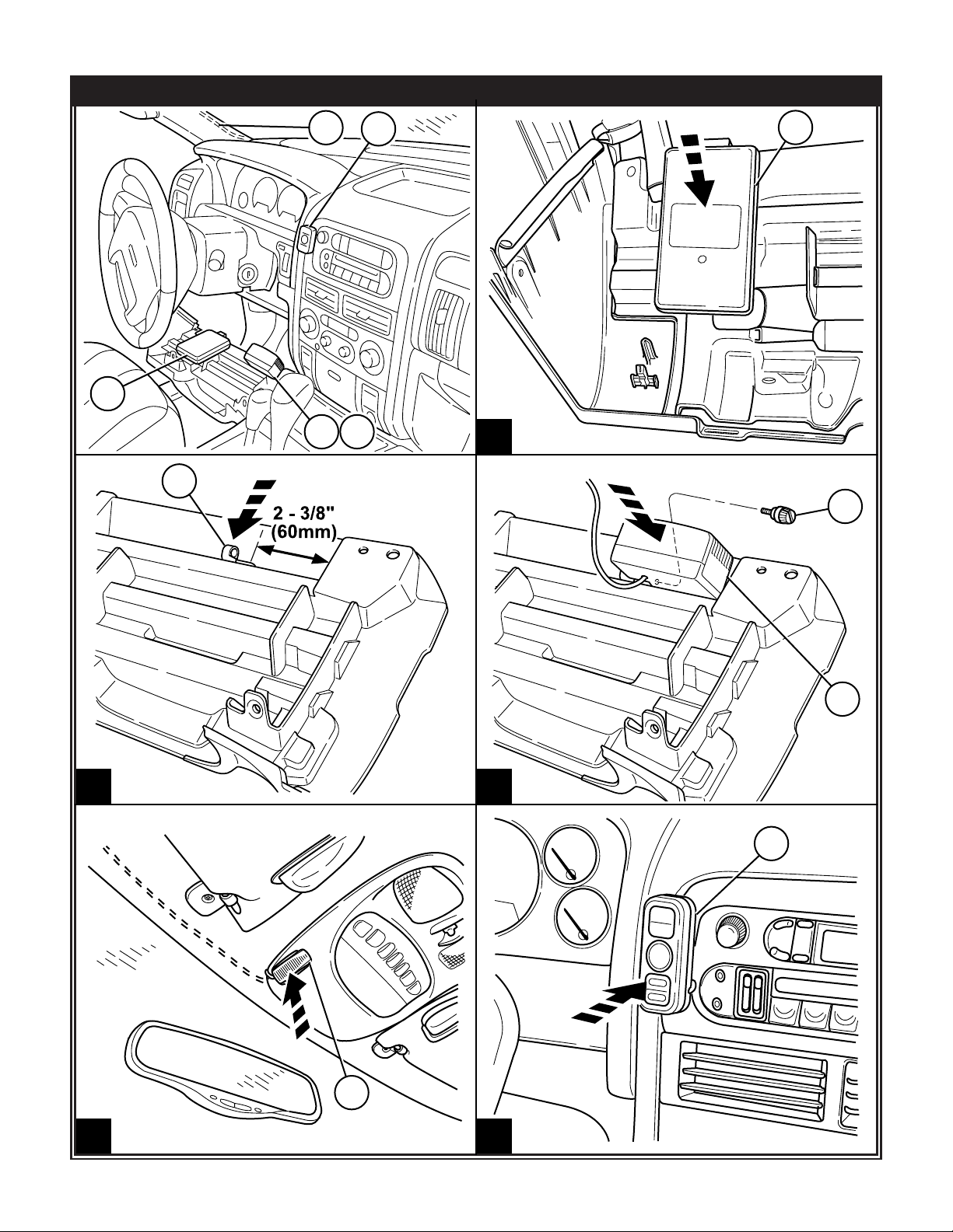
JEEP GRAND CHEROKEE
01-12-2004 19 of 20 K6858681
1
2
3
5
4
B
A
B
A
C
D
E
D
E
B
C
Page 5

01-12-2004 20 of 20 K6858681
FUNCTIONAL CHECK PROCEDURE
1. Turn Ignition key to On position and turn radio on
– Both amber light indicators on the UConnect control pad will illuminate momentarily (approx. 3 seconds)
2. Press UConnect Button on the control pad
– System prompt will announce “UConnect Ready”
– Radio audio will mute
– Say “Dial”, system should reply “Phone Not Available”
3. Push UConnect button again
– System prompts with a dual tone beep
– Radio will return to preset volume
Please follow included Owner’s Manual for system operation.
GB
E
F
PROCEDIMIENTO DE VERIFICACIÓN FUNCIONAL
1. Gire la llave de Encendido hacia la posición ON y encienda el radio.
– Ambos indicadores de luz color ámbar en el cojín de control UConnect se encenderán por un momento
(3 segundos, aprox.)
2. Presione el botón UConnect en el cojín de control
– Un aviso del sistema anunciará "UConnect Ready" (UConnect Listo)
– El radio quedará en silencio
– Diga "Dial" (Marcar). El sistema debe responder "Phone Not Available" (Teléfono no disponible).
3. Presione el botón UConnect nuevamente
– SEl sistema responderá con un sonido de dos tonos
– El volumen del radio regresará a su valor preestablecido
Para operar el sistema, siga las instrucciones que parecen en el Manual del Propietario.
VÉRIFICATION DU FONCTIONNEMENT
1. Mettre le contact et allumer la radio
– Les deux témoins jaunes du pavé de commande Uconnect s'allument brièvement (environ 3 secondes)
2. Appuyer sur le bouton Uconnect du pavé de commande
– Un message vocal annonce << Uconnect Ready >>
– La radio se met en sourdine
– Dire : << Dial >>, le système doit répondre << Phone Not Available >>
3. Appuyer de nouveau sur le bouton UConnect
– Le système produit un bip à double tonalité
– La radio repasse au volume préréglé.
Voir les instructions d'utilisation dans le manuel de l'appareil.
 Loading...