

Page 1

Installation Instructions
for EVS Security Systems
SECURITY
SYSTEMS
Note: It is recommended that this installation take place prior to rustproofing.
The individual delivering the vehicle should review the
operation of this security system and any optional
features with the owner of the vehicle. Please place the
operating instructions in the glove compartment with the
vehicle Owner's Manual.
Please review these instructions completely before begin-
ning the installation of this vehicle security system.
INS0969
REV. A
7/00
TECHNICAL SUPPORT
Technical Support is available to authorized MOPAR dealers by
calling 1-800-34-MOPAR (1-800-346-6727). Please have your
dealer code number and VIN available when calling. Technical
Support hours are 9:00 AM (EST) - 8:00 PM Monday - Friday and
10:00 AM - 2:00 PM Saturday. 24 hour automated assistance is
available for answers to frequently asked questions by calling the
FAXBACK information system at (248) 589-5297.
Page 2

AIR BAG WARNING!
THE AIR BAG SYSTEM IS A SENSITIVE AND COMPLEX
ELECTROMECHANICAL UNIT. BEFORE BEGINNING THIS
INSTALLATION YOU MUST FIRST DISCONNECT AND
ISOLATE THE NEGATIVE BATTERY CABLE (GROUND).
AFTER DISCONNECTING THE NEGATIVE BATTERY
CABLE, WAIT AT LEAST ONE MINUTE BEFORE
CONTINUING TO WORK ON THE VEHICLE. FAILURE TO
DO SO COULD RESULT IN ACCIDENTAL DEPLOYMENT
OF THE AIR BAG AND POSSIBLE PERSONAL INJURY. THE
FASTENERS, SCREWS, AND BOLTS ORIGINALLY USED
FOR THE AIR BAG COMPONENTS HAVE SPECIAL
COATINGS AND ARE SPECIFICALLY DESIGNED FOR THE
AIR BAG SYSTEM. THEY MUST NEVER BE REPLACED
WITH ANY SUBSTITUTES. ANY TIME A NEW FASTENER IS
NEEDED, REPLACE WITH THE CORRECT FASTENERS
PROVIDED IN THE SERVICE PACKAGE OR FASTENERS
LISTED IN THE PARTS BOOKS. SAFETY GLASSES SHOULD
BE WORN AT ALL TIMES.
This device complies with FCC rules part 15. Operation is subject to the
following two conditions: (1) this device may not cause harmful
interference and (2) this device must accept any interference that may
cause undesired operation.
Changes or modifications not expressly approved by the party responsible
for compliance could void the user’s authority to operate the equipment.
2
Page 3
1. Installer Preparation
A. Required Tools:
Wire cutter/strippers
Assorted Screwdrivers
Assorted Nut drivers
Voltmeter
Soldering iron
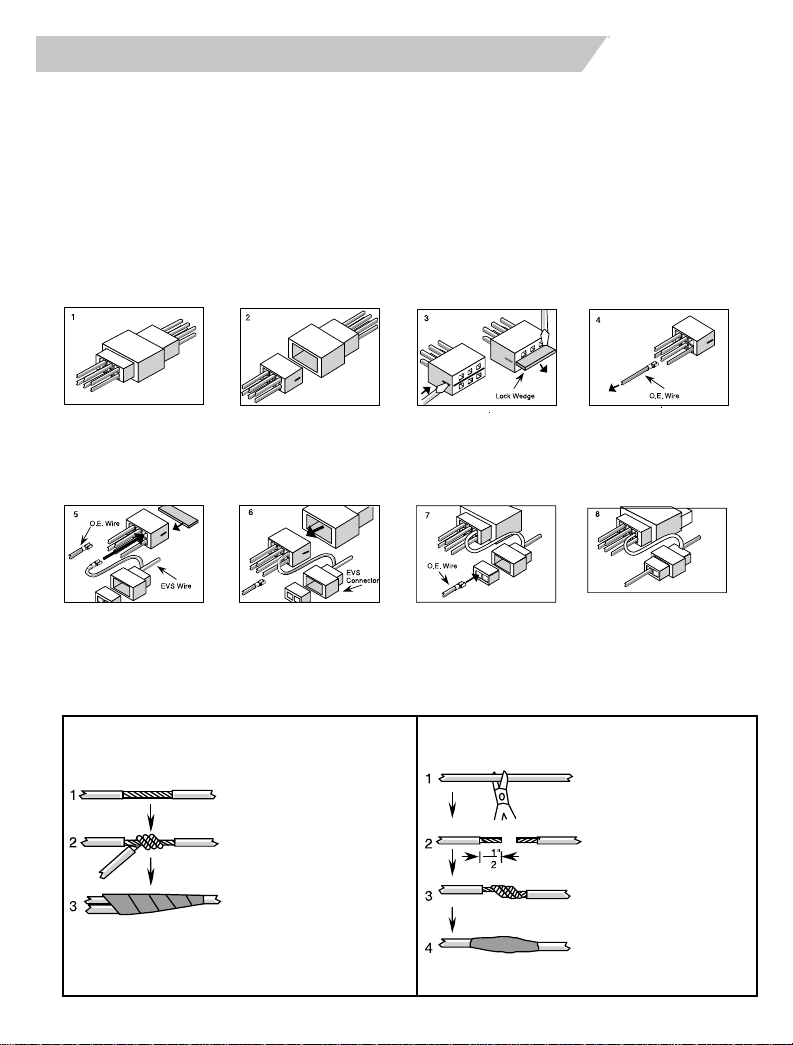
B. Connection Procedures
Remove and Replace Procedure
Razor Knife
Electrical Tape
Acid free solder rosin core
Crimping Pliers
Locate the appropriate
connector.
Insert the appropriate
EVS wire into the
cavity. Replace the
locking wedge.
Center Splice Procedure Strip and Splice Procedure
Separate the connector
ends.
Plug the two connectors
back together.
Strip back the wire
insulation.
T wist and solder EVS wire
onto the exposed wire.
Cover with a minimum 4
wraps of tape.
Remove the locking
wedge.
Insert the vehicle wire into
the appropriate cavity on
the EVS connector.
Remove the appropriate
wire(s) by releasing the
tang inside the connector
with a terminal extraction
tool.
Insert the locking wedge
into the EVS connector
and plug the two mating
EVS connectors together.
Cut wire.
Strip back insulation
from both ends.
T wist and solder each wire
to EVS wire harness.
Cover splice with
tape or heat shrink
tubing.
1
/2”
3
Page 4
1. Installer Preparation (Con’t)
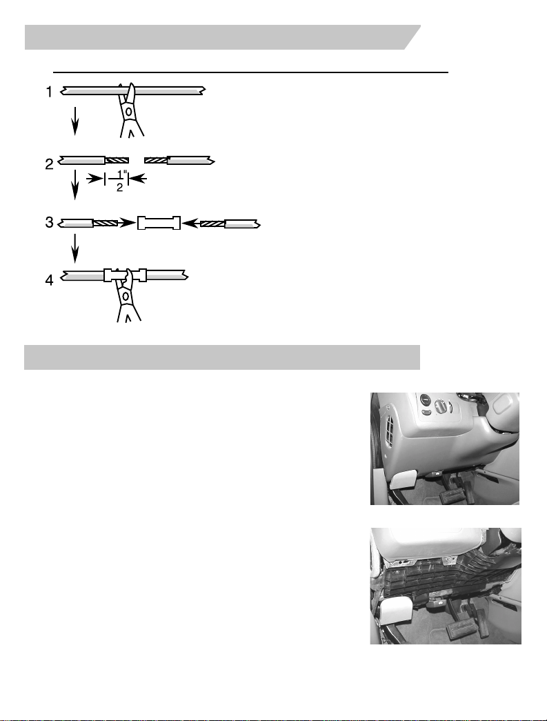
1. Cut wire.
2. Strip back insulation 1/2" from
both ends.
3. Insert wire ends into butt
connector.
4. Crimp center of butt
connector. Pull wires to verify
that the connection is secure.
2. Main Harness Connection
Po wer and Ignition Connection
1. Remove the underdash and knee blocker panels by
removing 4 philips screws. (FIGURE 2.1)
2. Remove the crush panel and support brace by
removing 12 philips screws. (FIGURE 2.2)
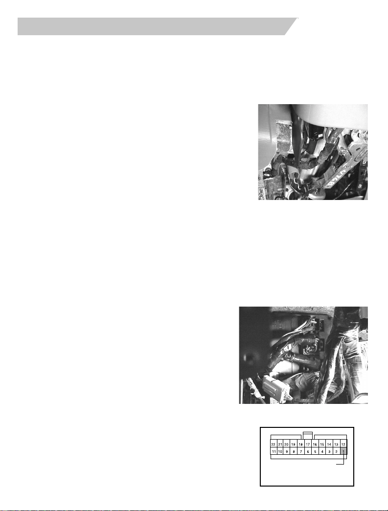
3. Access the 5-way ignition switch connector
harness on the left side of the steering column.
(FIGURE 2.3) Strip back the factory tape to expose
the wires coming from the switch.
4. Locate the L.BLUE/RED 20-gauge wire located in
cavity #5 of the ignition switch connector.
This wire should measure constant +12v.
5. Center splice the EVS 20-gauge L.BLUE/RED wire
into the vehicle’s L.BLUE/RED wire.
(Follow the Center Splice procedure on page 3.)
6. Locate the PINK/WHITE 20-gauge wire located in
cavity #3 of the ignition switch connector. This wire
should measure +12v only when the ignition is in
the run position and 0 volts when its in the off position.
7. Center splice the EVS 20-gauge PINK/WHITE wire into the vehicle’s
4
20-gauge PINK/WHITE wire.
FIG. 2.1
FIG. 2.2
Page 5
2. Main Harness Connection
8. Locate the YELLOW 20-gauge wire located in cavity #4 of the ignition switch
connector. This wire should measure +12v only when the vehicle is cranked with
the key.
9. Using wire cutters, cut the 20-gauge YELLOW wire in half. Tr y to create this cut
about 2 or 3”s away from the ignition switch connector, remove more harness
tape wrap if necessary.
THE FOLLOWING CONNECTIONS MUST BE
MADE IN THE PROPER POLARITY . IF THE
WRONG WIRES ARE CONNECTED THE VEHICLE WILL NOT START AND THE CONNECTIONS WILL HAVE T O BE REVERSED. READ
THE FOLLOWING CAREFULLY.
10. Using the supplied RED butt connectors, splice
the EVS 20-gauge YELLOW/BLACK wire to the
previously cut 20-gauge YELLOW wire coming
from the ignition switch connector.
(Follow crimping procedure outlined on page 4).
11. Splice the EVS 20-gauge YELLOW wire to the previously
cut YELLOW wire which goes toward the wire harness.
Ground Connection
1. Locate a vacant area of metal on the support brace to use as a chassis ground.
2 Attach the EVS BLACK ground wire to the area chosen by inserting the supplied
screw through the ground ringlet and into this area.
3. Make sure the ringlet is securely tightened.
FIG. 2.3
Dome Light Connection
1. Locate the BCM against the drivers side
bulkhead. Locate the 34-way C2 connector
which is the second connector from the top
on the BCM. (FIGURE 2.4)
2. Locate the 20-gauge YELLOW/ORANGE wire
located in cavity #25 of the C2 connector. This
wire will register 12V+ when the dome light is
on and ground when the dome light is off.
3. Center splice the singular EVS 20-gauge
YELLOW/ORANGE wire that is tapped to the
EVS harness into this vehicle’s YELLOW/
ORANGE wire.
(Follow the Center Splice procedure on page 3)
4. Insert the terminal on the other end of the EVS
wire into pin position #1 of the EVS module’s
22-way connector. (see diagram on page 13)
FIG. 2.4
DOME LIGHT
Viewed from wire end
5
Page 6
3. Alarm Connections
A. Siren
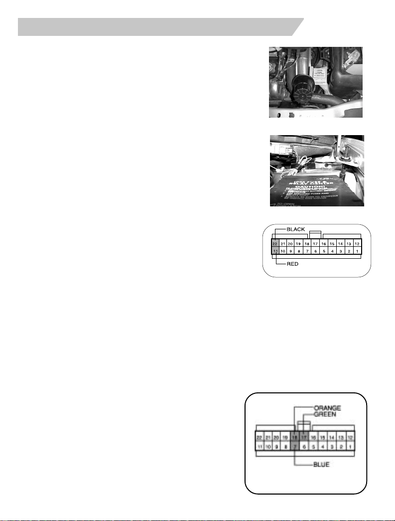
1. Locate siren mounting location on the front
frame rail area. (FIGURE 3.1)
2. Hold siren in mounting location and mark
mounting holes.
3. Drill three (3) 1/8" mounting holes.
4. Remove siren mounting bracket bolt.
5. Use three (3) of the supplied 1/4" sheet metal
screws, secure the siren mounting bracket.
6. Secure the siren to the siren mounting bracket.
7. Route the siren wires through the hood release
Bulkhead Panel grommet. (FIGURE 3.2)
Secure siren wires as necessary with the
supplied tie wraps.
8. Insert the siren wires into the 22-way module
connector.
a. RED into cavity # 11.
b. BLACK into cavity #22.
Viewed from wire
B. Multi-Function Status Indicator / Push-button
1. Find a mounting location for the status indicator that is visible
from outside the vehicle.
2. Make sure that there is at least 2" clearance behind the selected mounting
location and any vehicle components.
3. Drill a 5/16" mounting hole. Then, using a small file notch the mounting hole
to accommodate the key way on the switch body.
4. Feed the status indicator wires through the mounting hole and snap the
switch body firmly into the hole. Depress the switch a few times to ensure
that it travels freely. If necessary, carefully
enlarge the hole.
5. If necessary, slide the retaining r ing over
the back of the switch body.
6. Insert the status indicator wires into the
22-way module connector:
FIG. 3.1
FIG. 3.2
6.1. BLUE wire into cavity #7.
6.2. GREEN wire into cavity #17.
6.3. ORANGE wire into cavity #18.
VIEWED FROM WIRE END
OF CONNECTOR
6
Page 7
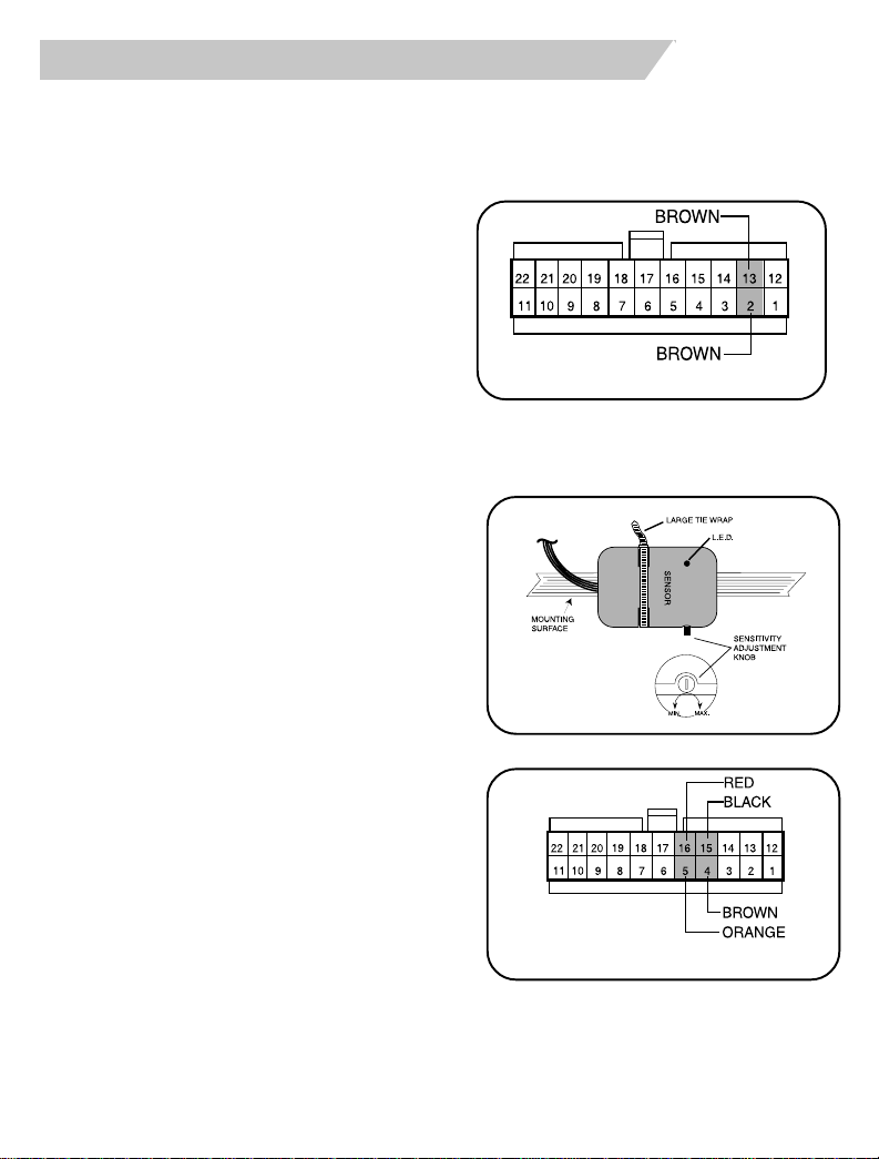
3. Alarm Connections
C. Emergency Override / Programming Button
1. Find a hidden (not plainly visible)
location underdash that is accessible
while sitting in the drivers seat. It
is suggested that the override
button be mounted in a different
location for each installation.
2. Drill a 5/16" mounting hole and
mount the disarm button.
3. Insert the BROWN disarm button
wires into cavities #2 & 13 of the
EVS 22-way connector. The
disarm button wires are
interchangeable.
D. Shock Sensor (Optional)
1. Find a mounting location for the
shock sensor. The sensor must
adhere to a surface (or wire
harness) under the instrument
panel that is in solid contact with
the vehicle chassis. The ignition
switch wiring harness is an
excellent choice. Be sure to mount
the shock sensor so that the L.E.D.
can be viewed when adjusting the
sensitivity.
2. Stick one of the supplied squares
of adhesive tape to the bottom of
the shock sensor case. Then
attach the sensor to mounting
surface. Use one of the supplied
long tie wraps to secure sensor
firmly in place.
3. Insert the shock sensor wires into
the 22-way module connector:
VIEWED FROM WIRE END OF CONNECTOR
VIEWED FROM WIRE END OF CONNECTOR
a. BLACK wire into cavity #15.
b. BROWN wire into cavity #4.
c. RED wire into cavity #16.
d. ORANGE wire into cavity #5.
7
Page 8
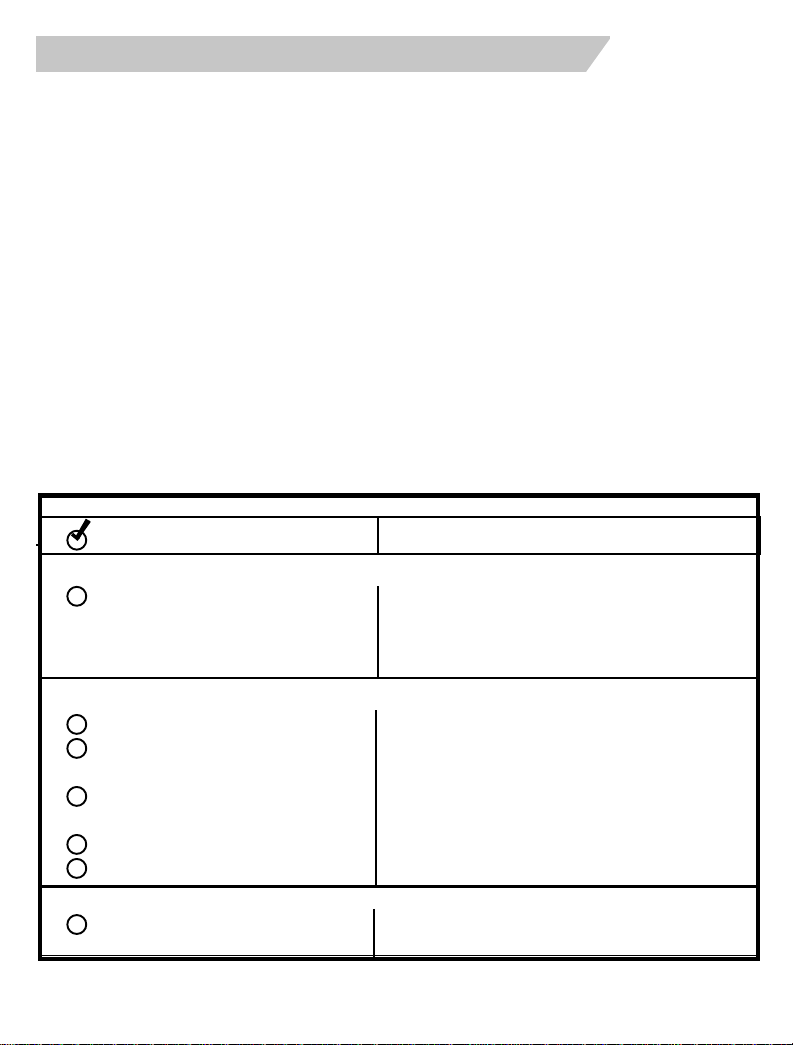
4. System Po wer-Up, T est, and Adjustment
A. System Power-Up
1. Recheck all connections and connectors to make sure they are properly
insulated.
2. Replace any vehicle fuses removed during the installation.
3. Plug the 6-way (power), and 22-way (accessory) harnesses
into the EVS module.
4. Tur n the ignition key to the ON position.
5. Replace the module power fuse on the 6-way harness.
6. Tu r n the ignition key OFF.
B. System Test
Before testing the system operation, make sure to roll the drivers door window down.
If any of the following items fail to function properly, refer to the appropriate section
in the installation manual and double check all wiring, connector pin outs and fuses.
Before replacing the module or any of the systems components, contact technical
service at the number listed on the front cover of this manual.
Operation Tr oubleshooting Pr ocedure
WHEN ARMING THE SYSTEM CHECK THE FOLLO WING:
Siren chirps twice Make sure domelight is off
All entrances must be secured
Check connections
WHEN SYSTEM IS FULLY ARMED, CHECK THE FOLLO WING:
Status light flashes (steady rate) Check connections
All doors & hatch (hood and/or
trunk if connected) trip alarm Check connections
Shock sensor trips alarm (full
alarm and lite-touch) (optional) Check and adjust sensitivity
Engine will not start / alarm trips Check connections
Manual override disarms alarm Make sure ignition is on
WHEN DISARMING THE SYSTEM CHECK THE FOLLO WING:
Domelight Turns On Check connections
8
Page 9
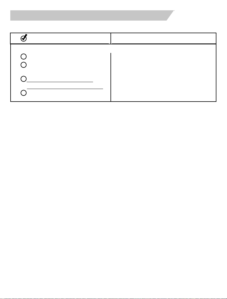
4. System Power -Up, T est, and Adjustment
B. System Test (cont.)
Operation T roubleshooting Pr ocedure
AFTER THE SYSTEM HAS BEEN DISARMED, CHECK THE FOLLOWING:
Engine will start Check connections
Transmitter range (attempt
operating system from 25-50 feet) Relocate antenna
Valet Mode (refer to Owner’s
Manual for valet mode operation) Review operation procedure
Headlamp Illumination (if equipped) Review operation procedure
Control Module Mounting
After all electrical connections are complete, and the system operation has been
verified, use the supplied tie wraps to securely attach the control module to a solid
underdash wire loom or support bracket. Make sure that the module and wiring
harnesses do not in any way interfere with the brake, clutch, or the accelerator
pedals.
Shock Sensor Adjustment (Optional)
1. Close all doors and arm the system.
2. Moving around the vehicle, using an open palm slap various body panels on
the vehicle.
• A light to medium blow should cause the siren to emit a short chirp.
• A medium to heavy impact should trip a full alarm cycle.
3. Adjust the shock sensitivity up or down as need to achieve the desired setting.
4. Reassemble all interior components removed during the installation.
Mounting the Antenna
For optimum performance, the antenna must be mounted as high as possible in the
vehicle.
• Do not mount the antenna and/or module in an area which is totally enclosed
in metal. Keep the antenna element as straight as possible.
• Do not coil any of the remaining antenna cable. For best results, make sure
that the antenna cable is completely uncoiled.
• Due to the nature of the antenna, there will be nulls in RF reception around the
vehicle. By slightly moving the antenna element these RF nulls can be reduced
and/or shifted in a different direction.
9
Page 10
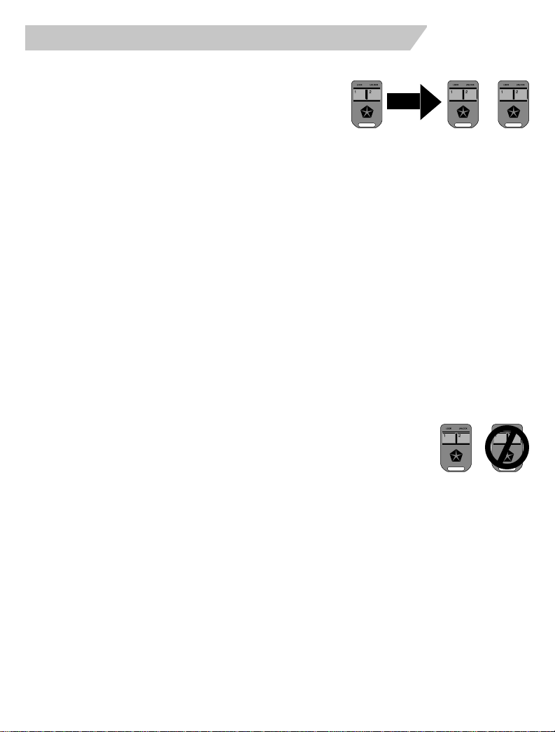
4. System Po wer-Up, T est, and Adjustment
C. Programming Additional Transmitters
Up to four transmitters can be programmed to
the system.
1. Open the driver’s door.
2. Turn the vehicle ignition to the ON position.
3. Press and hold the Emergency Override / Programming button in.
•
After approximately 15 seconds, the siren will chirp 3 times. This indicates that
the system is in the Transmitter Programming Mode.
4. Release the Emergency Override / Programming button. Wait 5 seconds.
5. Press Button 1 on the new transmitter. The siren should chirp once.
6. Repeat step 5 for any additional transmitters.
7. Exit the Transmitter Programming Mode by turning the vehicle ignition off. Test all
remote transmitters to ensure that they work properly.
To delete a lost or stolen transmitter:
1. Follow steps 1-4 as described above.
2. Reprogram the remaining transmitters as described in step 5.
• If there is only one remaining transmitter, perform step 5 four times.
• If two remaining transmitters, perform step 5 twice for each transmitter.
D. Programming Selectable Options
1. Enter the Transmitter Programming Mode (steps 1-4 above).
2. Press and release Emergency Override / Programming Button once.
•
The siren will chirp three more times to indicate entry into the
Options Programming Mode.
3. Press Transmitter Button 1 to select Option 1.
4. Refer to the appropriate chart (next page) to change options.
10
Page 11
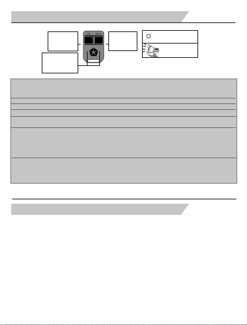
4. System Power -Up, T est, and Adjustment
Security Systems
ARM
BUTTON
Press to Advance
to Next Option
PRESS BOTH
BUTTONS
to Reset All Options
to Factory Settings
ARM DISARM
DISARM
BUTTON
Press to Turn
Option On or Off
T o exit Options Pr ogramming
, turn ignition off.
Mode
Status Indicator Displays
Option Status (On or Off)
Siren Chirps Denote
Option #
Option #
(# of times ARM
Description
Status Indicator
(Press Disarm
Button pressed)
1. N/A
2. N/A
3. Two-Vehicle Operation
4. Arm / Disarm Chirps
Remote operates two vehicles
Siren chirps when arming and disarming
vehicle
5. Passive Arming /
Starter Lockout Timer
Arms after 5 min.
Arms after 2 min.
(Skip if the system is to
be set for manual Arming
only)
6 and 7 Arming Characteristics
Passive Arming and Manual Arming
Passive Starter Lockout and Manual Arming
Manual Arming Only
(factory settings in bold)
6-0FF, 7-OFF
5. Updating the Owner’s Manual
Mark the selected operating characteristics and any additional features in the
spaces provided in the Owner’s Manual. Please review these sections with your
customer.
Make sure your customer is aware of the following:
• Location of the Emergency Override Button
• Procedure for obtaining additional transmitters
• System Warranty information
to Change)
OFF
ON
ON
OFF
6-ON, 7-OFF
6-OFF, 7-ON
11
Page 12
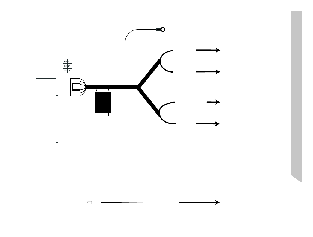
12
BLACK
System Layout
TO CHASIS METAL GROUND
6-WAY
SYSTEM MODULE
TO CAVITY # 1 OF THE EVS
22 WAY CONNECTOR
CONNECTOR
YELLOW/ORANGE
PINK/WHITE
L.BLUE/RED
YELLOW/BLACK
YELLOW
TO PINK/WHITE IGNITION
WIRE IN CAVITY #3 OF THE
IGNITION SWITCH CONNECTOR
TO L.BLUE/RED CONSTANT
+12V WIRE IN CAVITY #5 OF THE
IGNITION SWITCH CONNECTOR
TO YELLOW STARTER KEY
SIDE IN CAVITY #4 OF THE
IGNITION SWITCH CONNECTOR
TO YELLOW STARTER MOTOR
SIDE OF THE IGNITION
SWITCH CONNECTOR
TO YELLOW/ORANGE
DOME LIGHT WIRE IN
CAVITY #25 OF THE
34-WAY C2 CONNECTOR
Page 13
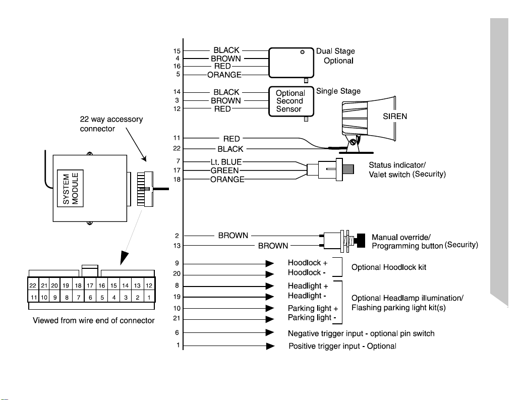
System Layout
Optional
Shock
Sensor
(
)
13
 Loading...