

Page 1

BACKUPCAMERA
DODGE/CHRYSLER
1
CALLOUTDESCRIPTIONQUANTITY
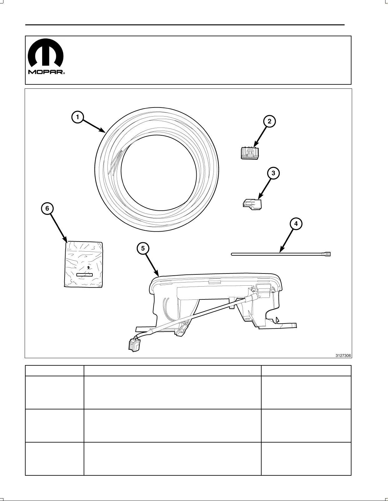
1Backupcameraharness1
2
3Backupcameraconnector1
4Zipties12
5
6
NOTE:AllviewsareDodgeunlessnoteddifferent,Chryslersimilar.
Nov16,2010K6861117
BackupcameraharnesstoT elematicsGatewayModule
(TGM)connector
Highmountbrakelampwithtrunkreleasebuttonandbackup
camera
SpliceKit(includes2splicecollarsandshrinktube)
1
1
1
Page 2
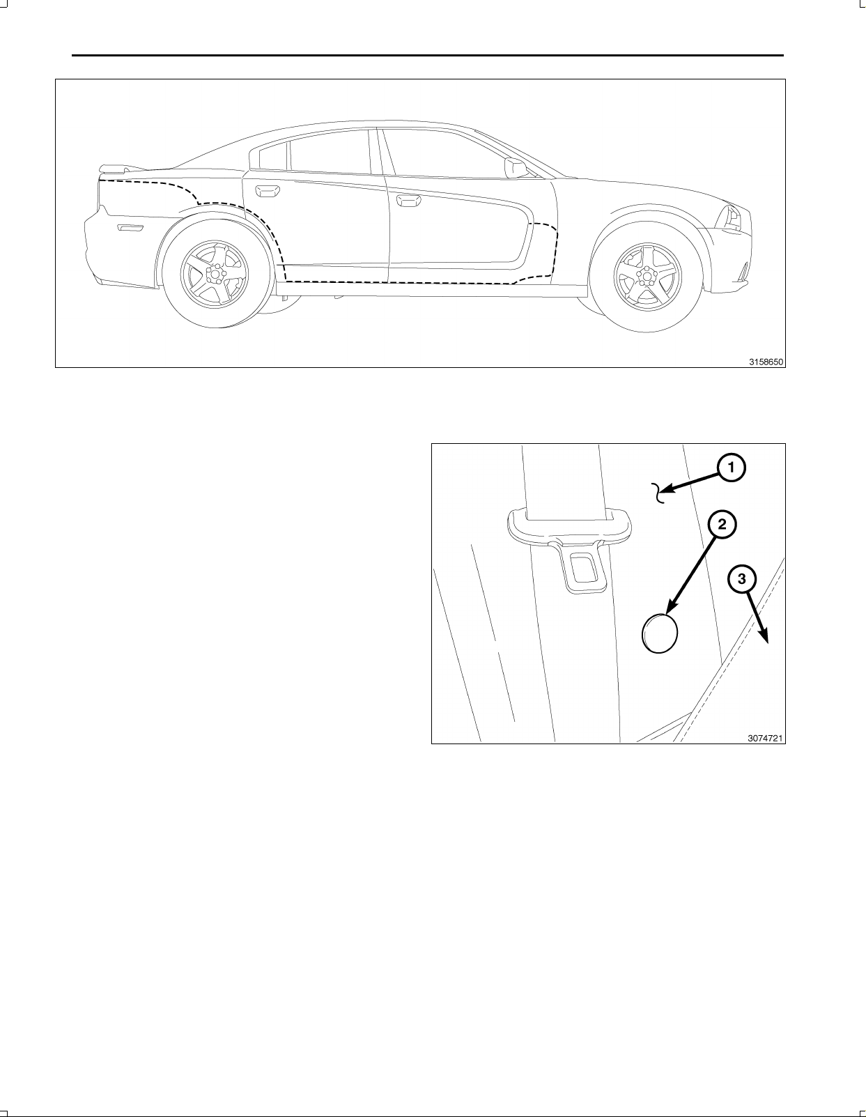
2
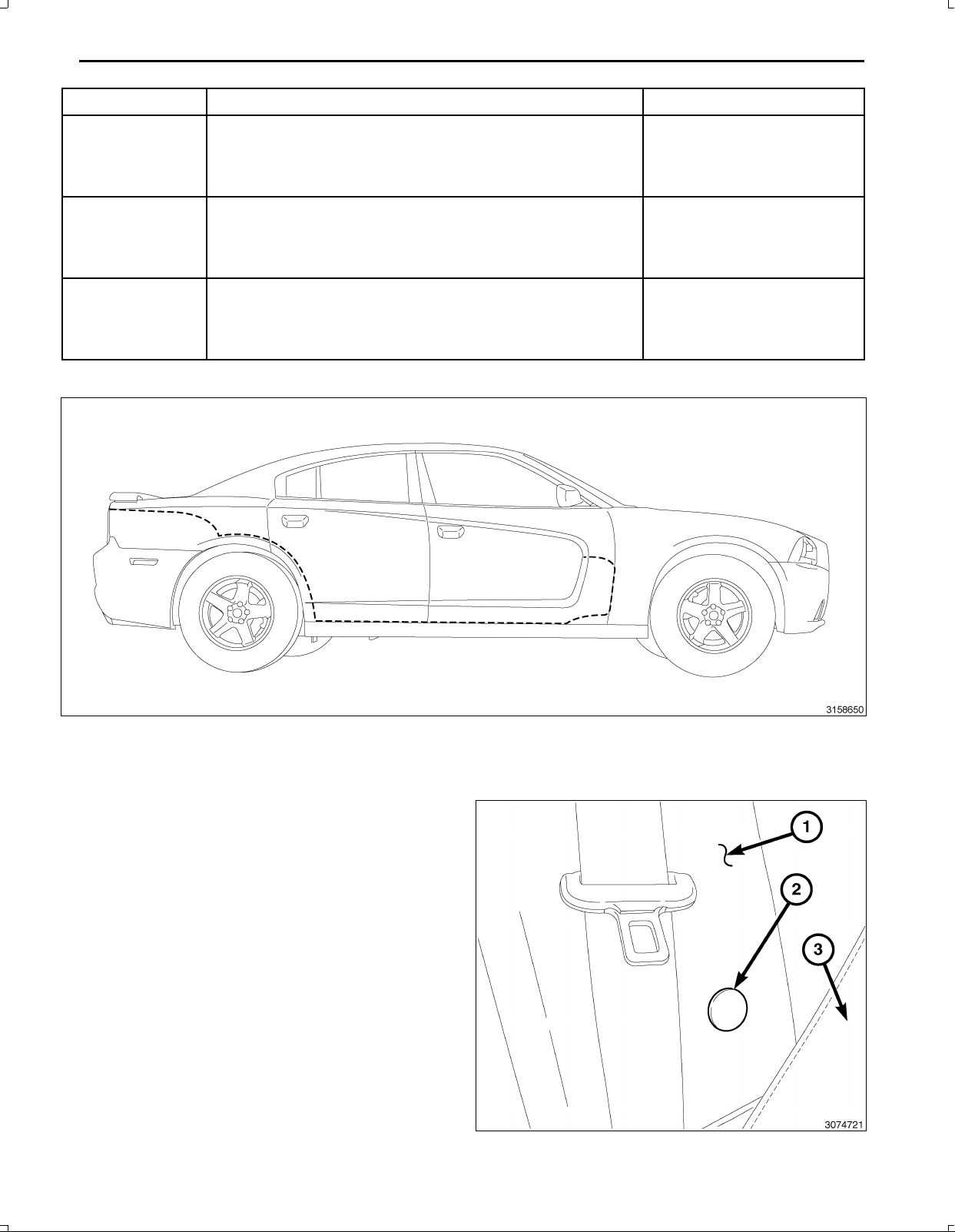
BackUpCameraHarnessRouting
PROCEDURESTEPS:
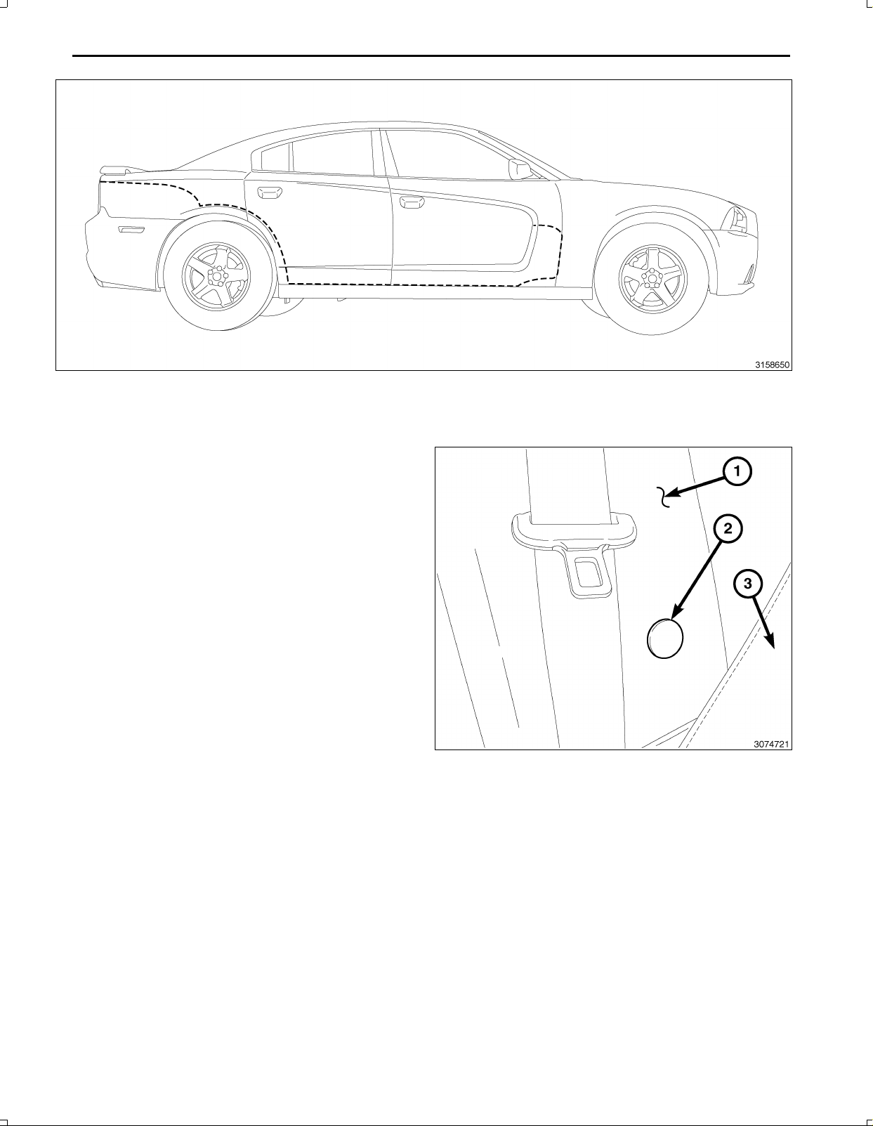
1.TilttheRHseatbackforaccesstotheBpillarlower
panelretainingscrew(notshown,underthecover,2),
ifequipped.
2.Ifequipped,usingtrimstickC4755orequivalent,re
movetheRHBpillarlowertrimpanelscrewcoverand
removetheretainingscrew.
Nov16,2010K6861117
Page 3
3.Applytheparkingbrake.
4.PlacetheignitionswitchtotheOnposition,applythe
servicebrakesandplacethegearselectorleverinto
theNeutralposition.
5.PlacetheignitionswitchtotheOffposition.
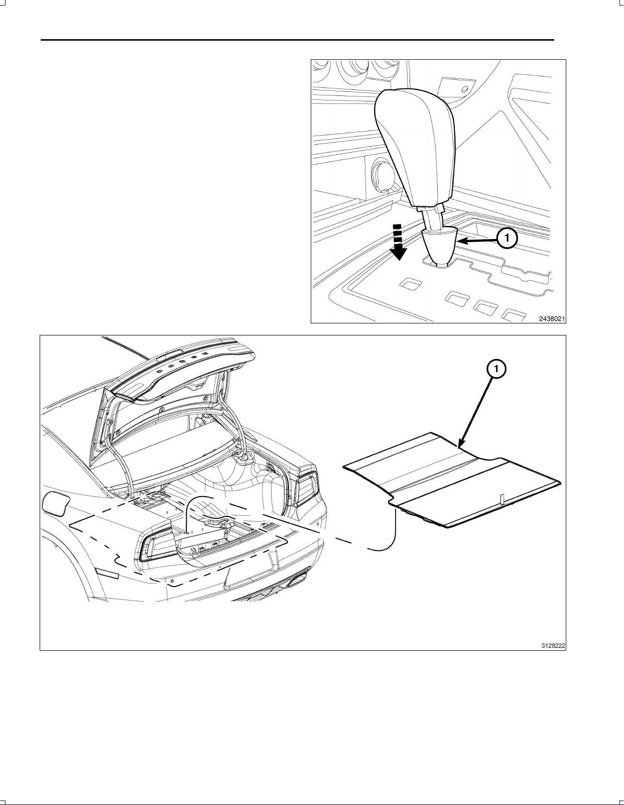
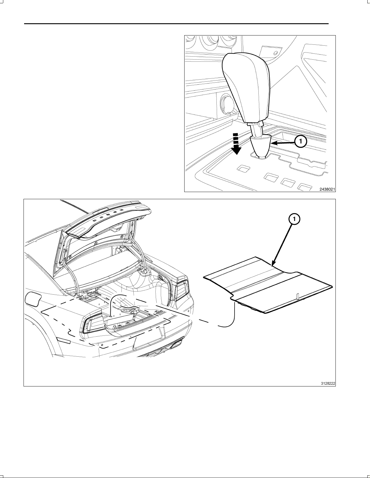
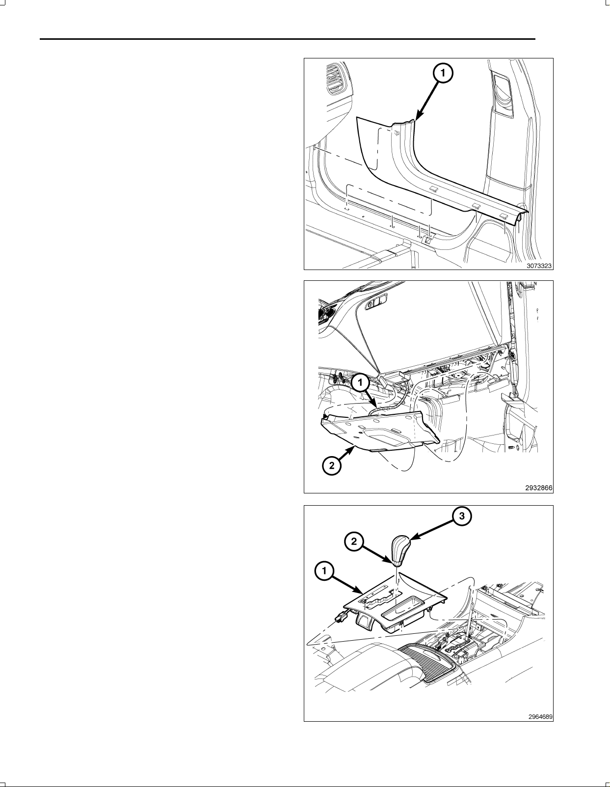
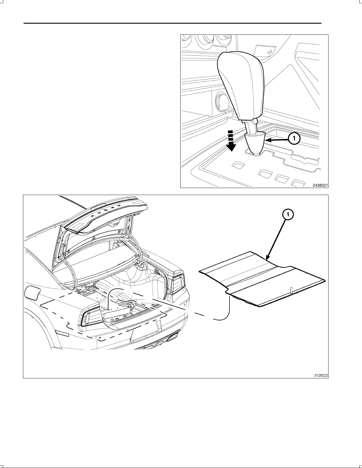
6.Usingasmallflatbladedtoolorequivalent,separate
theretainingring(1)andslidedowntheshiftershaft.
3
7.Removethesparetirecover/trunkfloorcarpetfromoverthesparetirewell.
8.Disconnectandisolatethebatterynegativecable.
Nov16,2010K6861117
Page 4
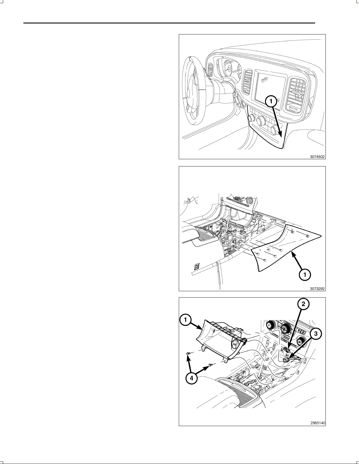
4
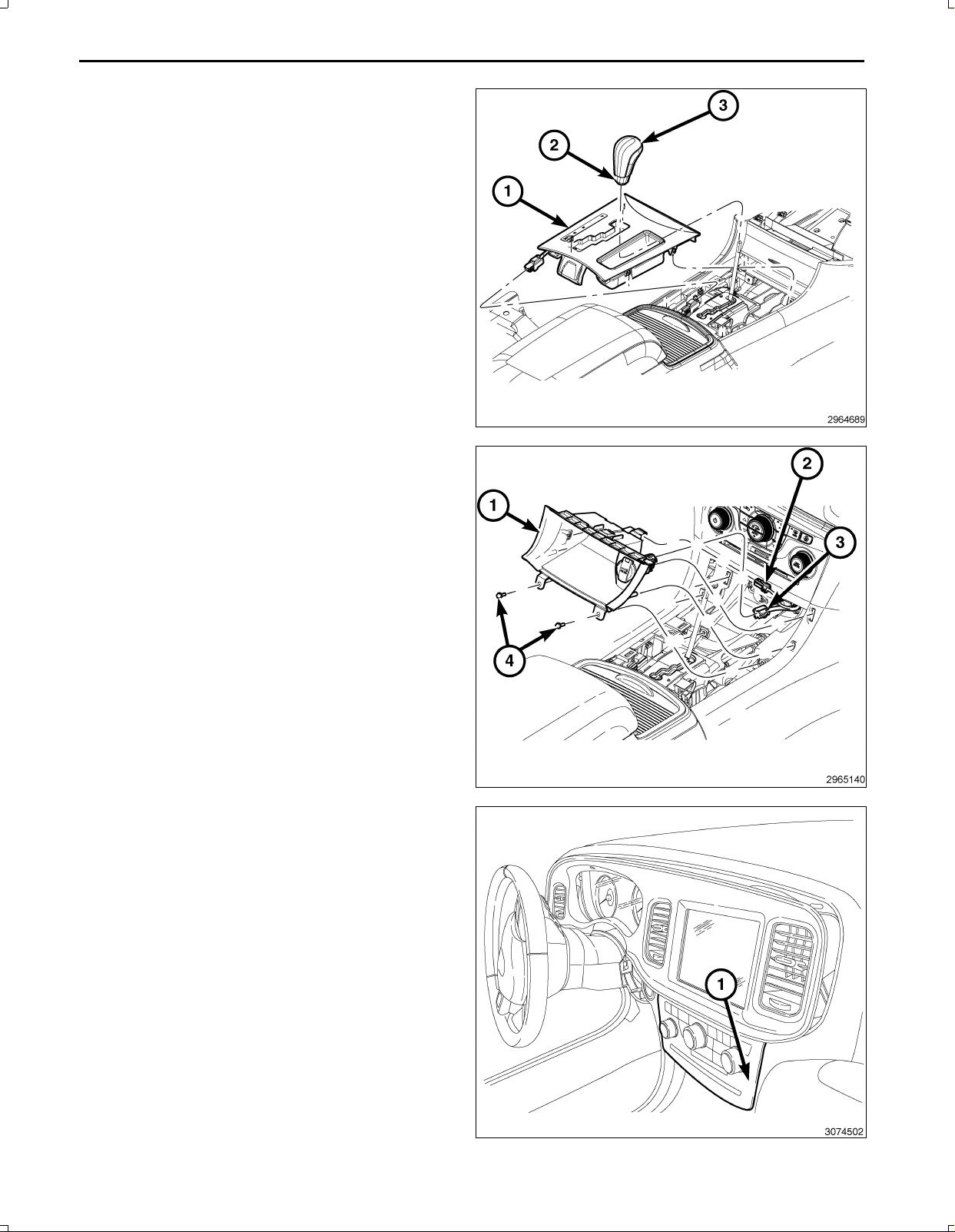
9.Usingathinwiretypetool,locateandpressthere
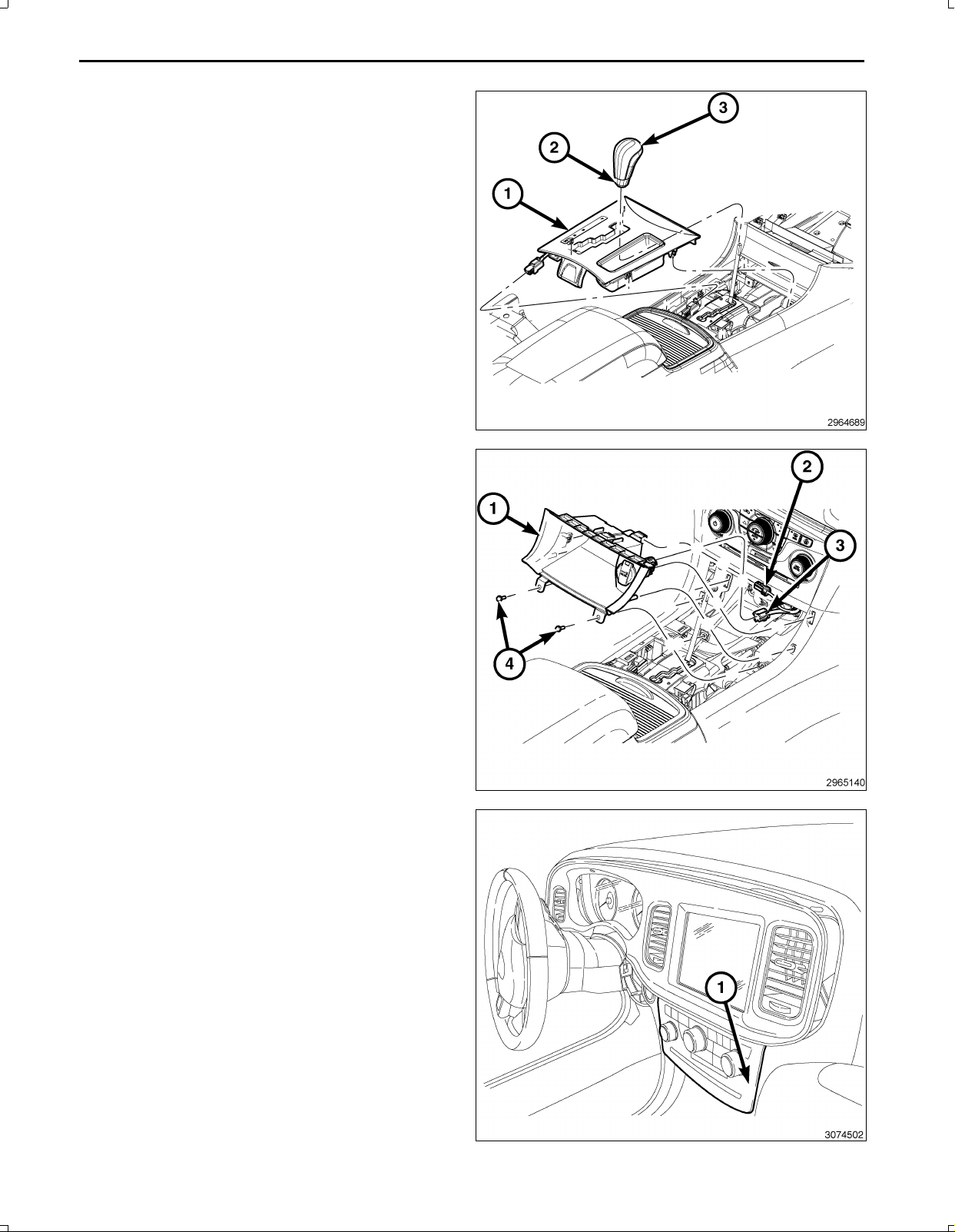
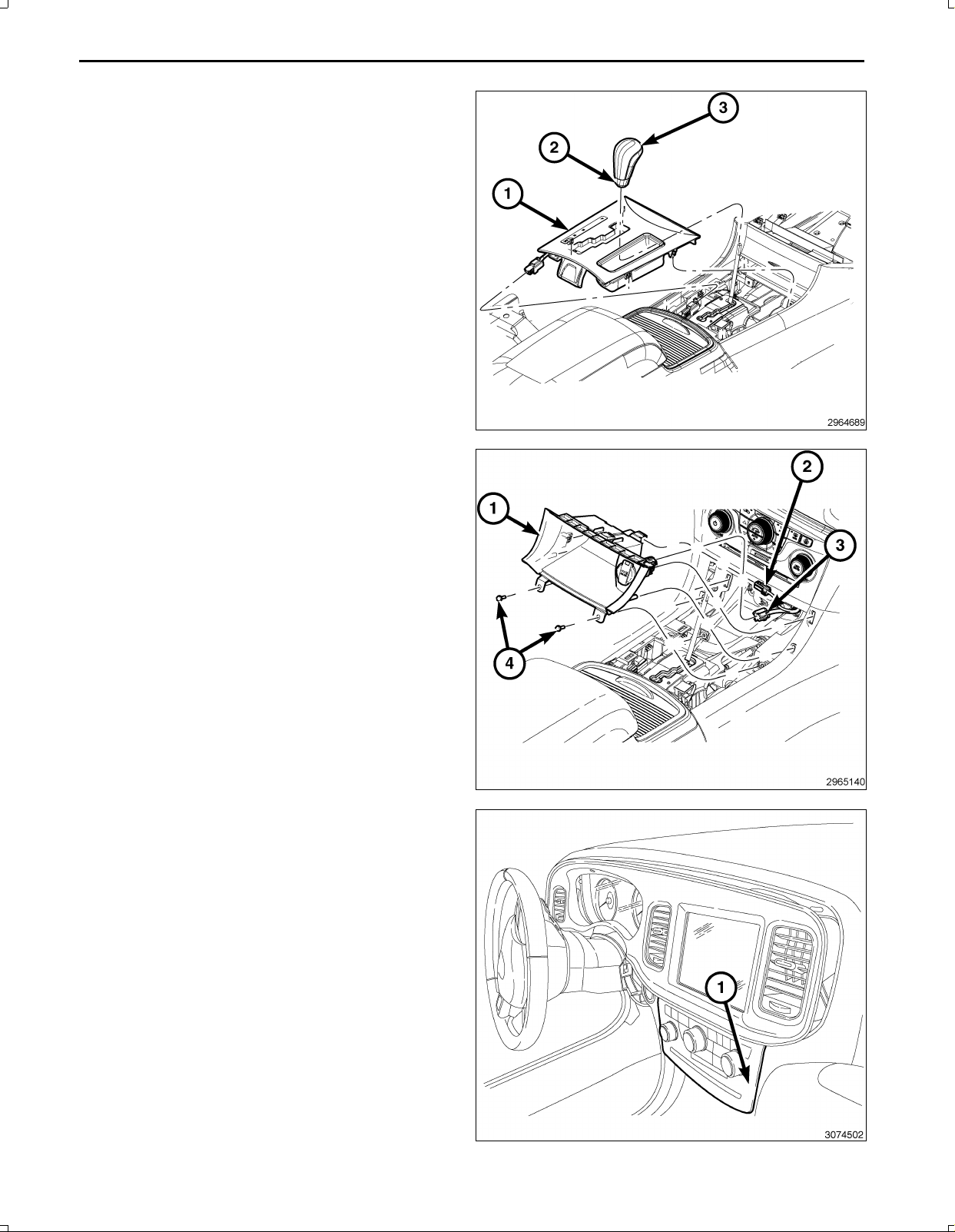
leasewhilepullingupontheshifterknob(3).
10.Removetheshifterknob(3)andretainingring(2).
11.UsingatrimstickC4755orequivalent,gentlyprybe
tweentheshifterbezel(1)andthefloorconsoletore
leasethesnapretainersthatsecurethebezel.Donot
pullwithexcessiveforceorfullyremoveatthis
time.
12.Disconnecttheshifterbezelwiringharnessandre
movetheshifterbezel(1).
13.Removethetwoscrews(4)securingthestoragebin
(1)totheconsole.
14.UsingatrimstickC4755orequivalent,gentlypry
betweenthestoragebin(1)andthefloorconsole
sidecloseoutpaneltoreleasethetwosnapretainers
thatsecurethestoragebin(1)tothefrontconsole
andcloseoutpanel.
15.Disconnectthe12Vignitionpoweroutletwiringhar
ness(3)fromtherearofthestoragebin(1).
16.DisconnecttheLED/Lampwiringharness(2)fromthe
storagebin(1)andremovethestoragebinfromthe
I/P.
NOTE:Onlydisconnecttheswitchbankassembly
wiringharnessconnectorbyfollowingthespecific
stepsfollowingthisstep.
17.UsingatrimstickC4755orequivalent,gentlyprybe
tweentheswitchbankassembly(1)andtheinstru
mentpaneltoreleasethesnapretainersthatsecure
theswitchbankassembly(1)totheinstrumentpanel
andpullawayfrominstrumentpanelforaccesstore
movetheconnectorusingthefollowingsteps:
Nov16,2010K6861117
Page 5
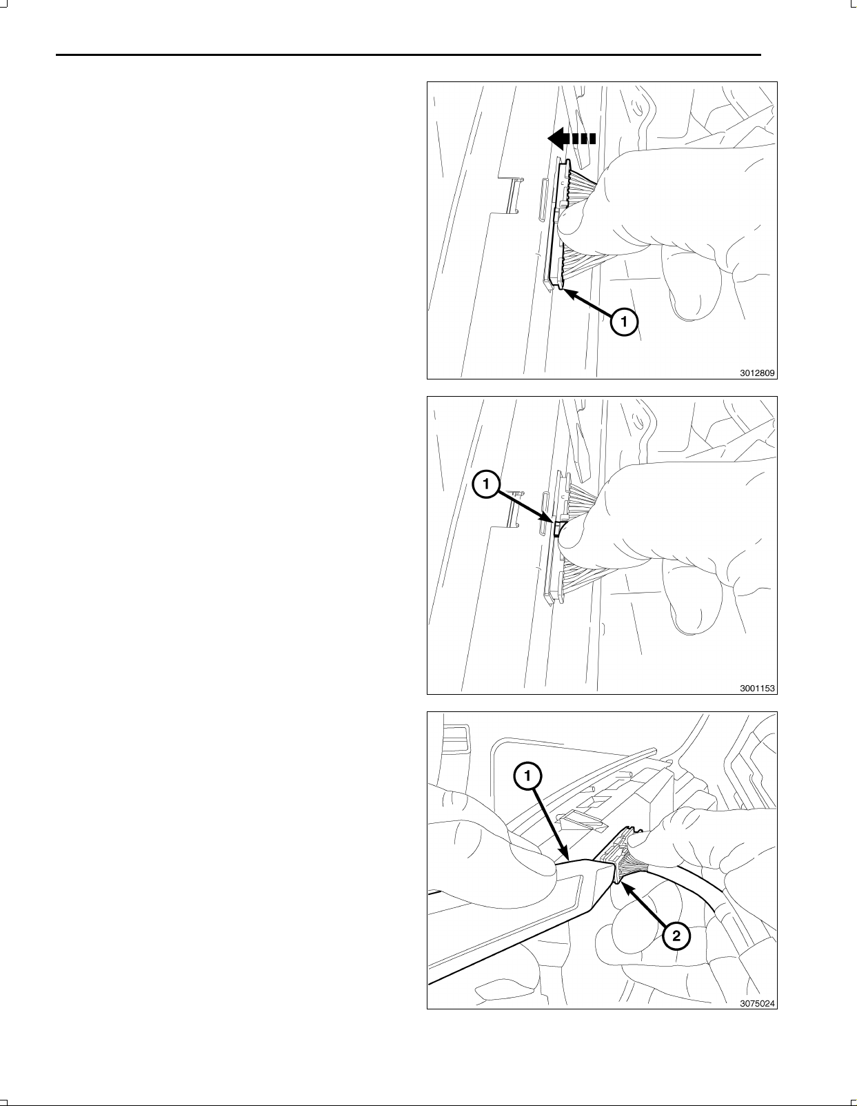
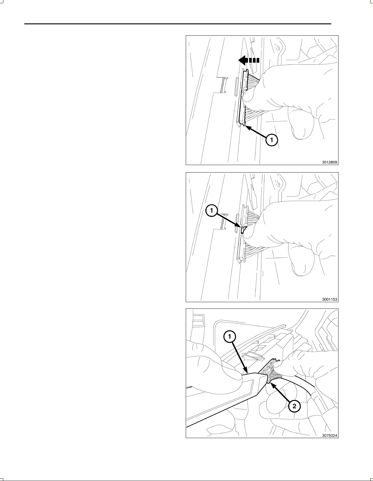
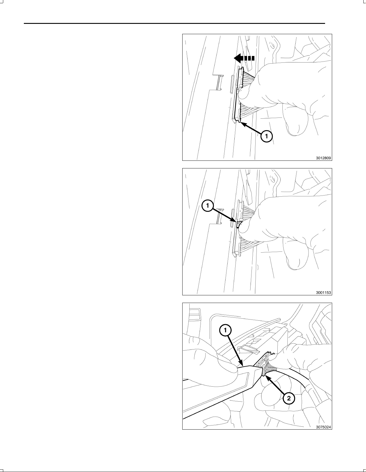
CAUTION:Neverpulltheconnectoroutbythewires.
Failuretofollowtheseinstructionswilldamageor
breakthewiresand/orconnector.
CAUTION:Pushthe40wayconnectorinbeforepush
ingonthelockingclip.Failuretofollowtheseinstruc
tionswilldamageorbreaktheconnectorlockingclip.
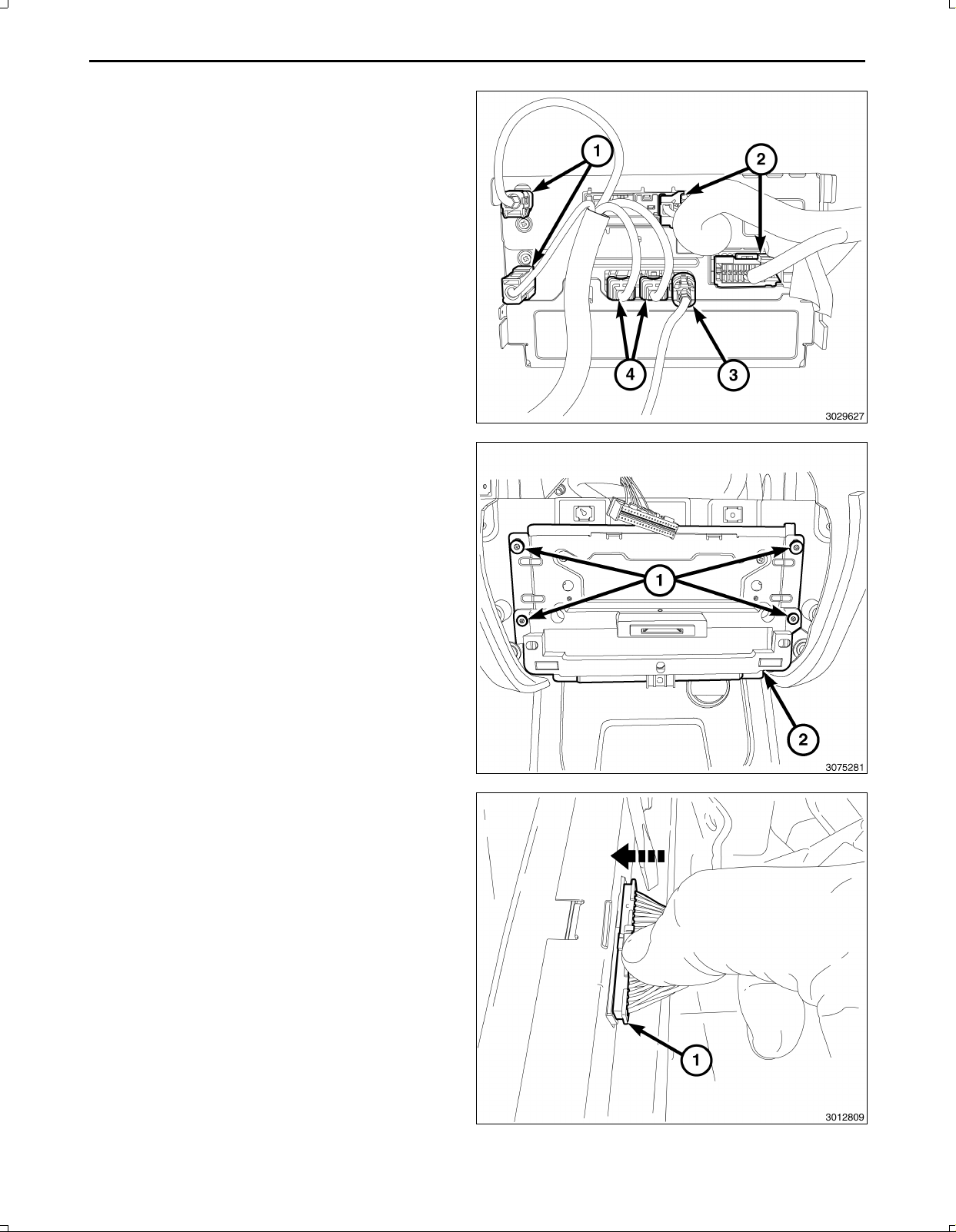
18.Pushinonthe40wayconnector(1)oftheswitchbank
assembly.
19.Gentlypushdownontheconnectorreleaselock(1).
5
20.UsingapocketscrewdriveroratrimstickC4755or
equivalent(1),gentlypryononesideoftheconnector
(2)toremove.
Nov16,2010K6861117
Page 6
6
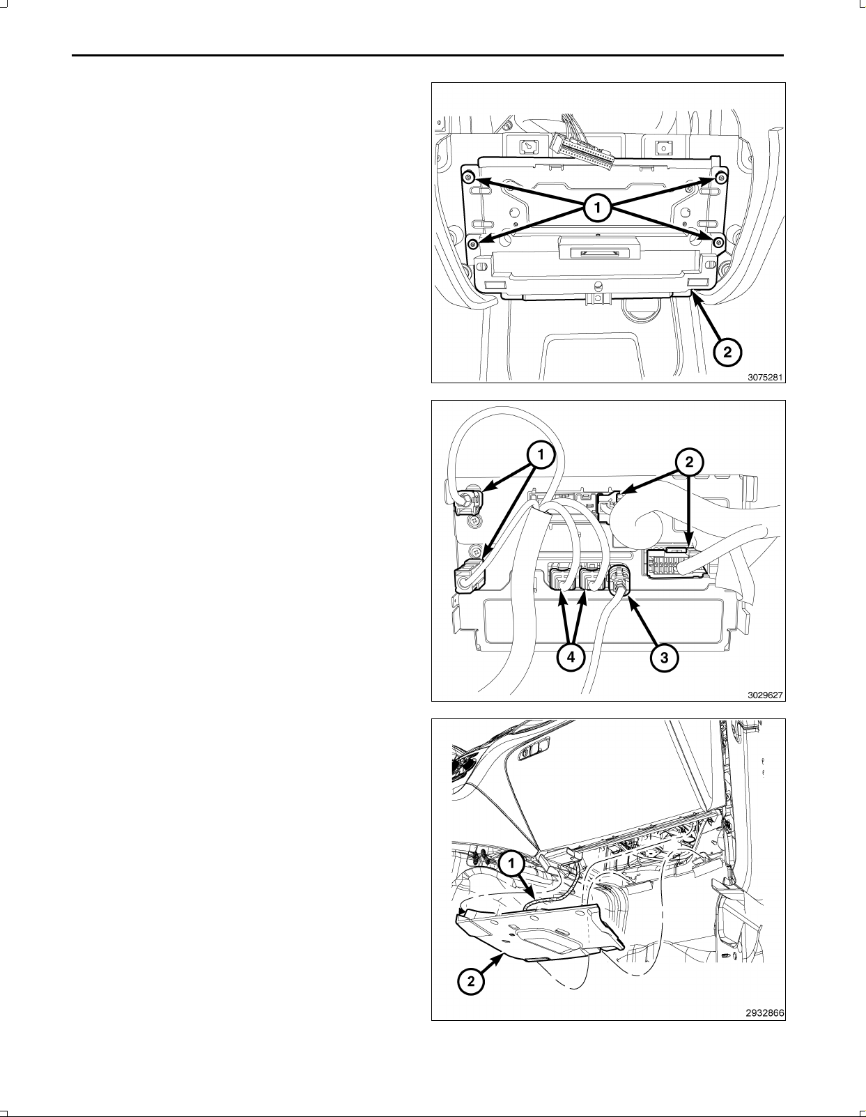
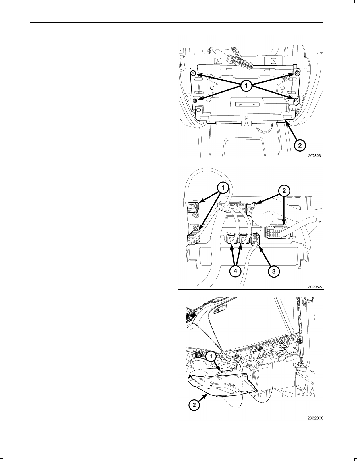
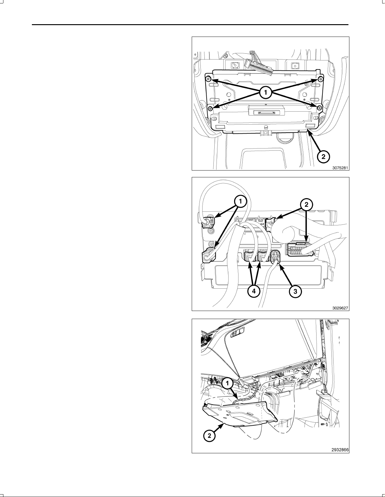
21.Removetheretainers(1)fromtheTelematicsGate
wayModule(TGM)(2)andpulloutfarenoughtoac
cesstheconnectorsonthebackoftheTGM.
CAUTION:Pullingtheantennacablestraightoutofthe
radiowithoutpullingonthelockingantennaconnec
torcoulddamagethecableorradio.
22.Disconnecttheantenna(s)(1),RFHUBandUCIca
bles(4),videocable(3)andwiringconnectors(2)from
theTGM.
23.RemovetheTGMfromthevehicle.
24.Removetherightsideinstrumentpanelsilencerpush
inretainers.
25.DisconnecttheLEDharness(1)andremovetheright
sideinstrumentpanelsilencer(2).
Nov16,2010K6861117
Page 7
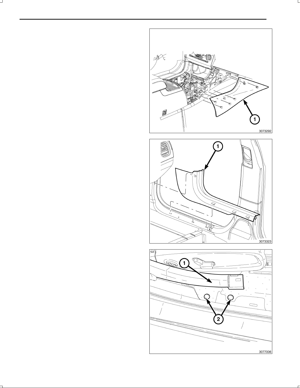
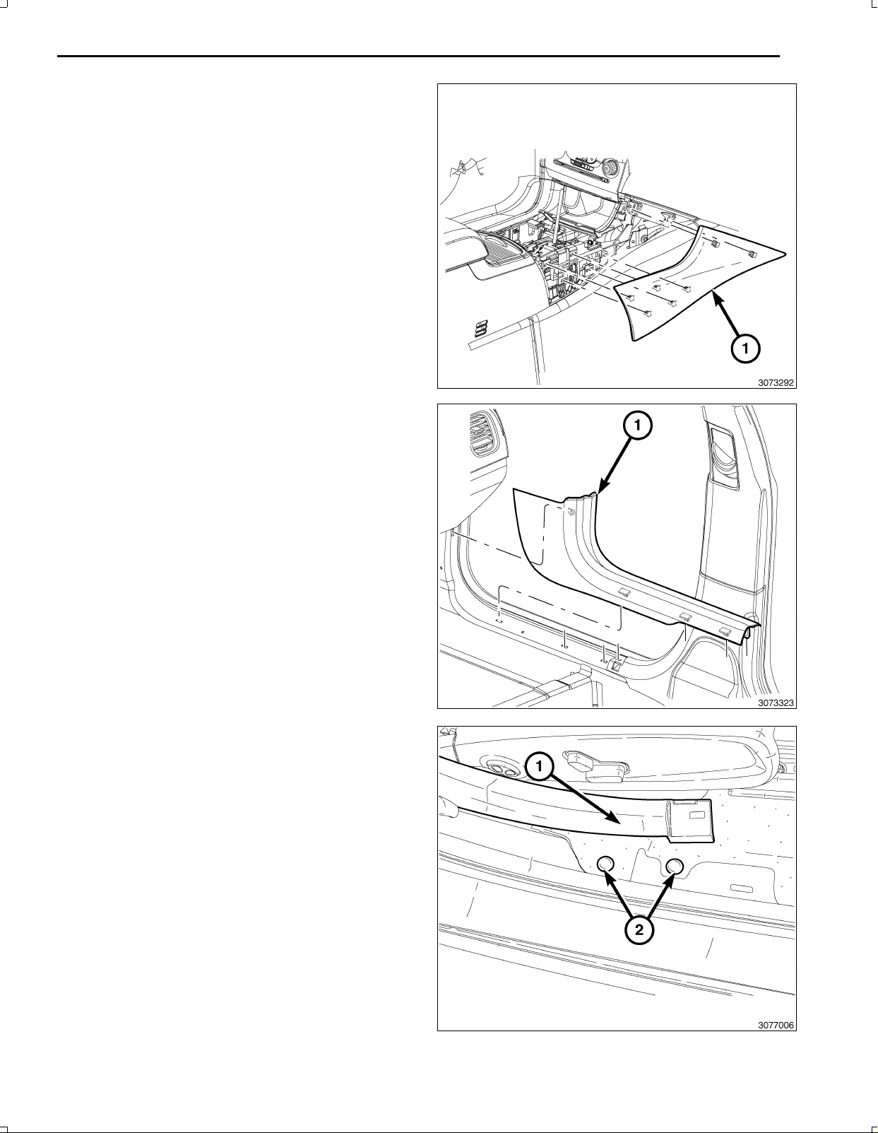
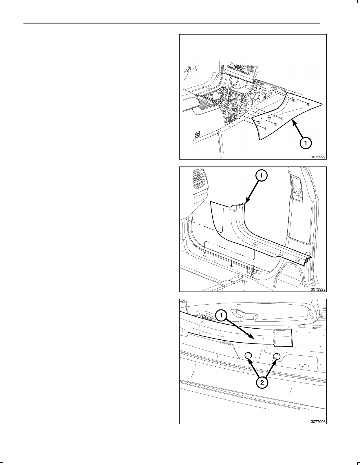
26.OntheRHsideandusingatrimstickC4755orequiv
alent,gentlyprybetweentheinstrumentpanelandthe
floorconsolesidecloseoutpanel(1)toreleasethe
twosnapretainersthatsecurethecloseoutpanelto
theinstrumentpanel.
27.UsingatrimstickC4755orequivalent,gentlyprybe
tweenthefloorconsolesidecloseoutpanel(1)and
thefloorconsoletoreleasethefivesnapretainersthat
securethecloseoutpaneltothefloorconsoleandre
movethepanel.
28.UsingatrimstickC4755orequivalent,removethe
RHfrontdoorscuffplate(1).
29.RemovetheRHreardoorscuffplatethesameasthe
front.
7
NOTE:ItisnotnecessarytoremovetheBpillartrim,
onlyloosenforaccesstoroutethebackupcamera
wiringharness.
30.AtthefrontoftheRHBpillarlowertrim,pullupand
towardtheseattoreleaseretainerclips.Repeatat
therearoftheBpillartrimtoloosenthelowerportion
oftrim.
31.Removeallcarpetpushinfastenersalongthefront
andrearscuffplatesandtheRHkickpanelarea.
Nov16,2010K6861117
Page 8
8
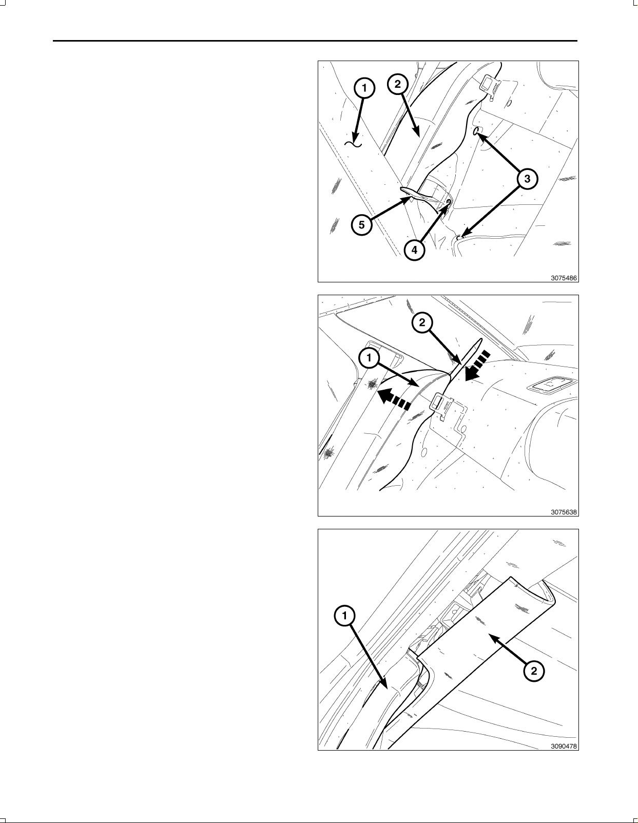
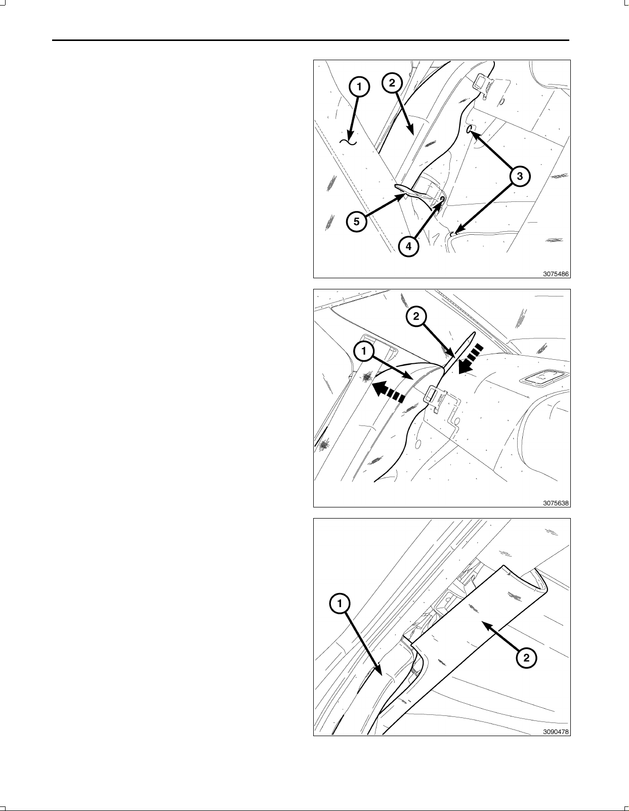
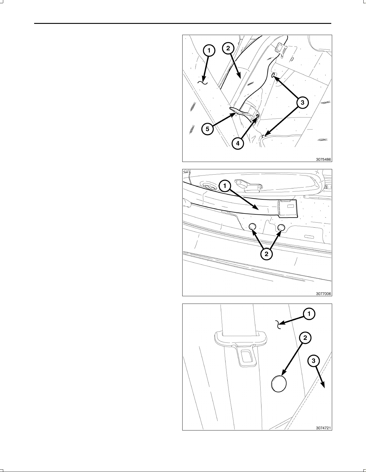
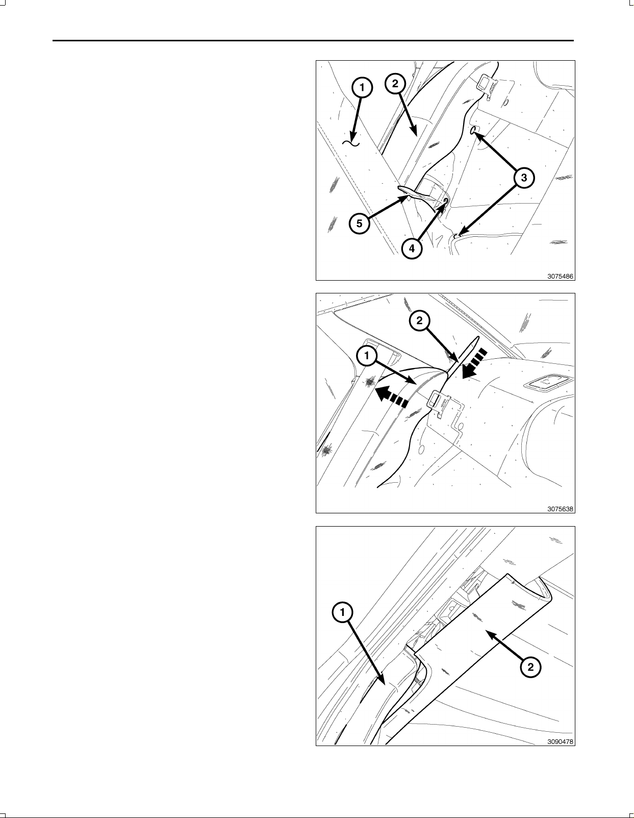
32.PulltheRHrearseatback(1)forward,exposingthe
luggagecompartment.
33.BehindtheRHrearseat,pullthecarpettab(5)up,
exposingtherearseatbacksidebolsterbracketre
tainingbolt(4).
34.RemovetheRHrearseatbacksidebolsterbracket
bolt(4).
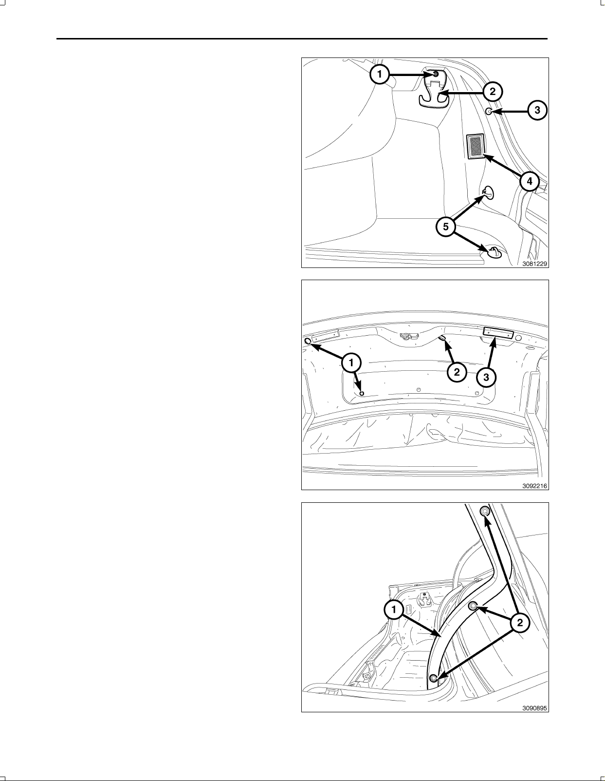
35.Removethepushinfasteners(3)thatsecurethe
trunksidetrim.
36.UsingatrimstickC4755(2)orequivalent,pushdown
betweentherearshelfandtheRHrearseatbackbol
ster(1)toreleasetheretainingclip,andpullouton
theseatbackbolster(1)toremove.
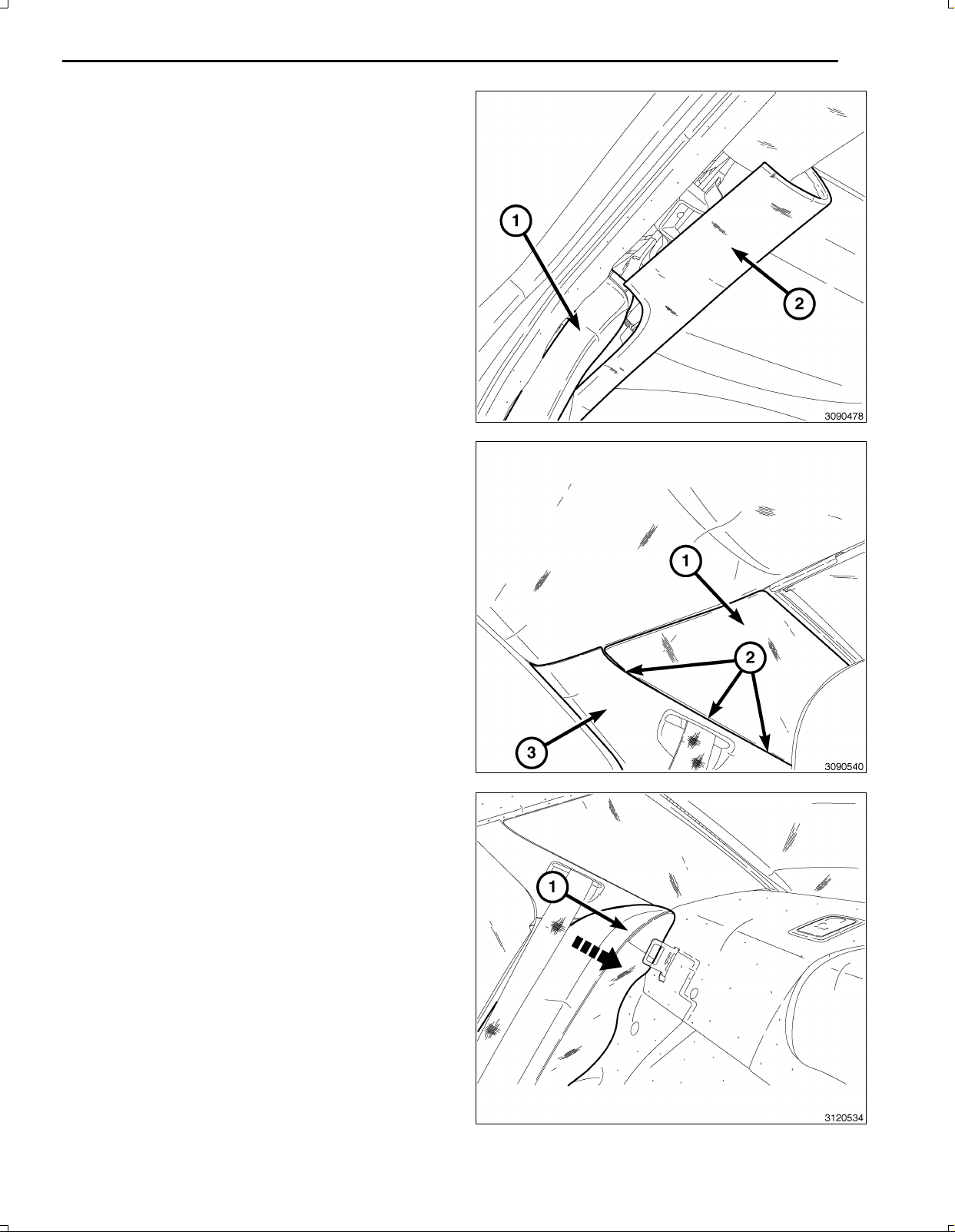
37.Dodgeonly,usingatrimstickC4755orequivalent,
carefullyprythequartertrim(2)looseenoughtore
moveCpillartrim(1).
Nov16,2010K6861117
Page 9
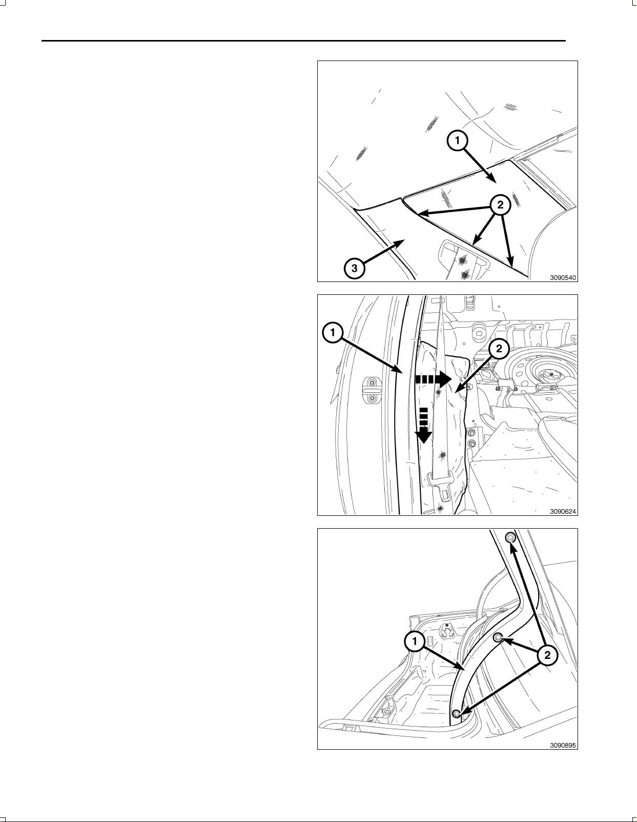
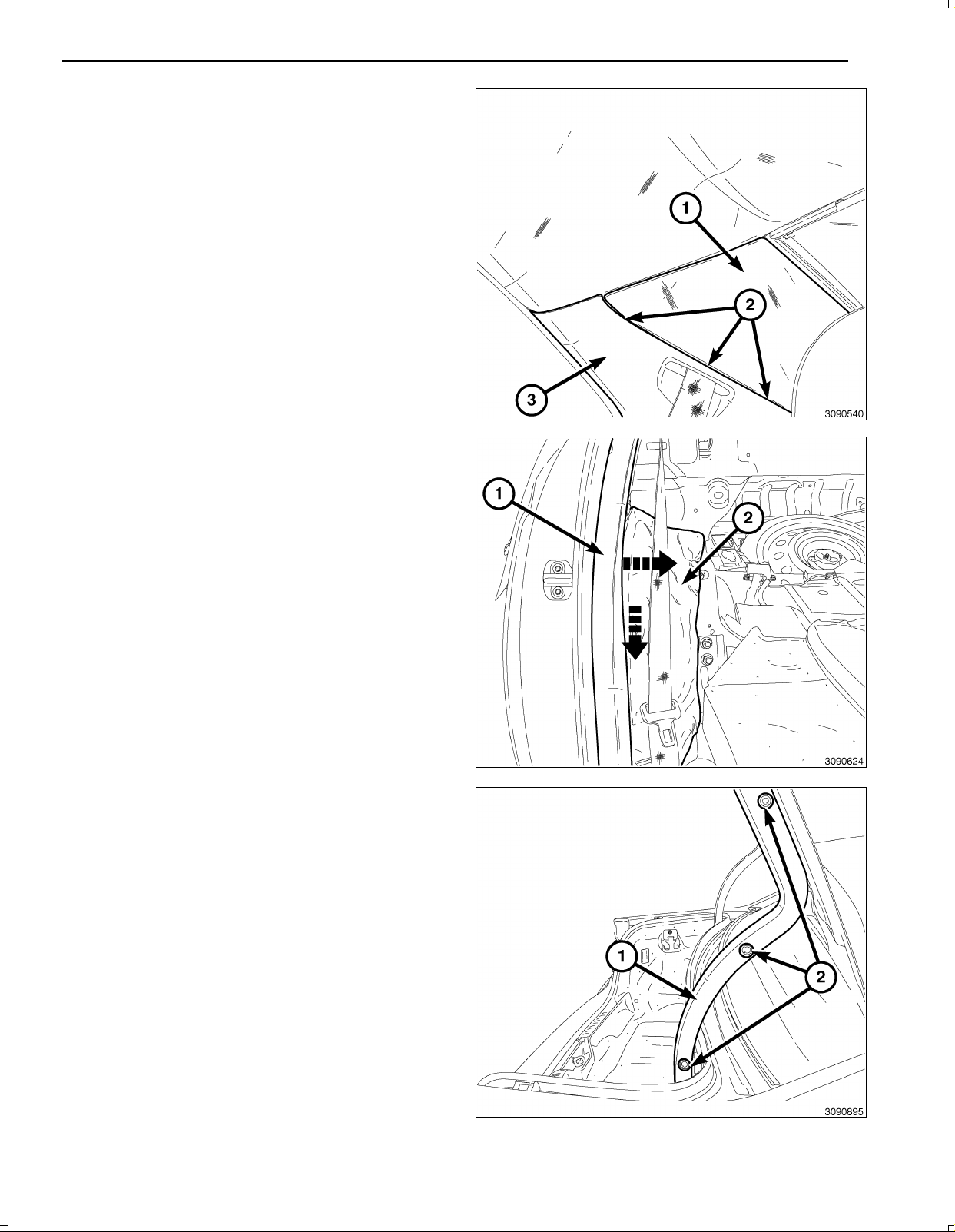
38.Chrysleronly,usingatrimstickC4755orequivalent,
carefullyprythequartertrim(1)atthreepoints(2)
looseenoughtoremovetheCpillartrim(3).
39.UsingatrimstickC4755orequivalent,carefullypry
theCpillartrim(1)inwardtoloosenthepushinre
tainers,thenpullforwardanddowntoremovefrom
thevehicle.
40.Foldbacktheinsulator(2)toexposewiringharness
routingarea.
9
41.Openthevehicletrunk.
42.RemoveRHhingetrimpushinfasteners(2)andre
movethehingetrim(1).
Nov16,2010K6861117
Page 10
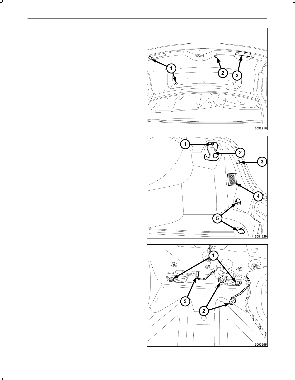
10
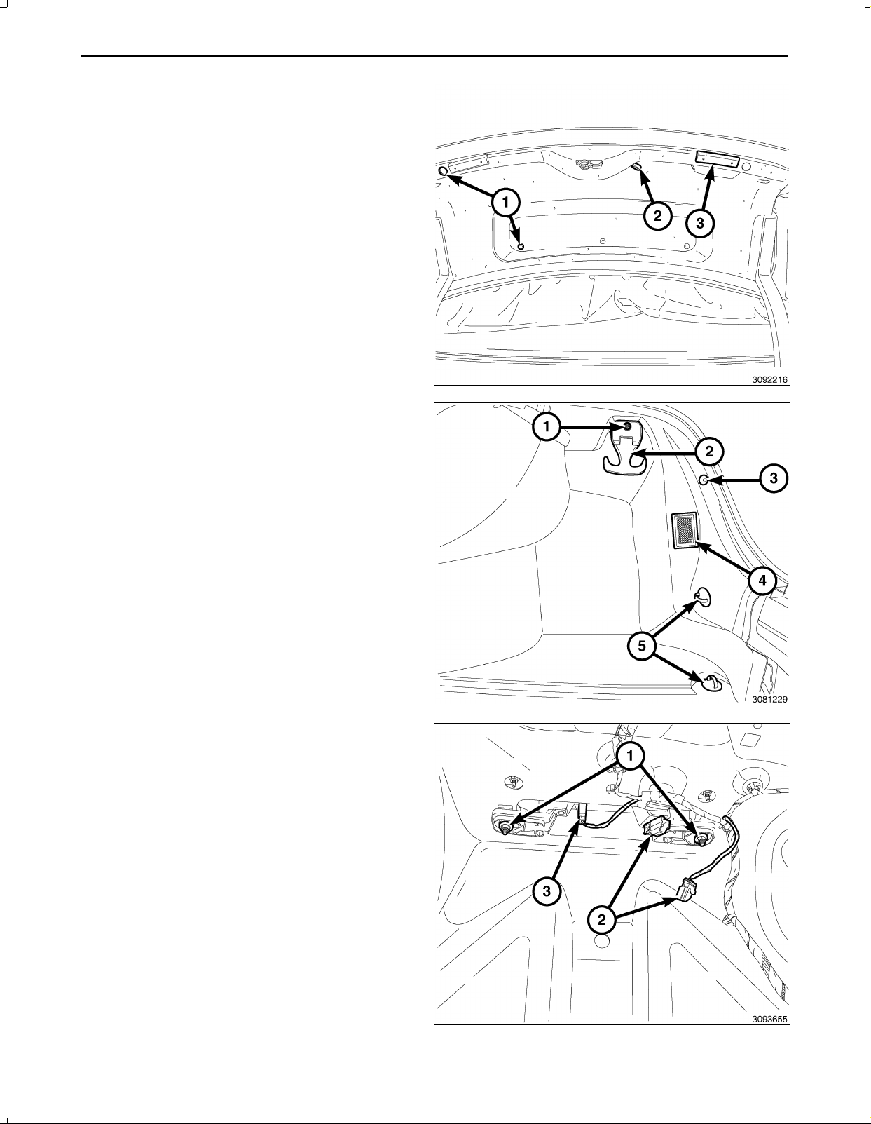
NOTE:Themanualtrunkreleasehandle(2)mustbe
routedthroughthedecklidtrim.
43.Removethetwobumperstops(3)andthenine
pushinretainers(1)fromthedecklidandremove
thedecklidtrimfromthedecklid.
44.Removethewheelwellcovertrimasfollows:
a.OntheRHside,removethecargonethookscrew
(1)anduppercargohook(2).
b.OntheRHside,removethepushinretainer(3)
thatsecuresthewheelwellcovertrim.
c.OntheRHside,removethecargonetlowerhooks
(5).
d.Carefullypullbackthewheelwellcoverenoughto
disconnectthetrunklamp(4)harnessconnector,
andremovethewheelwellcovertrim.
45.Disconnecttheswitchandlampelectricalharness
connectors(2,3).
NOTE:Afterremovingthenuts(1)thereareretaining
tabsnexttothestudsthatneedtobepushedinward
toremovethelampassembly.
46.Removethelampassemblynuts(1)andremovethe
lampassemblyfromthevehicle.
Nov16,2010K6861117
Page 11

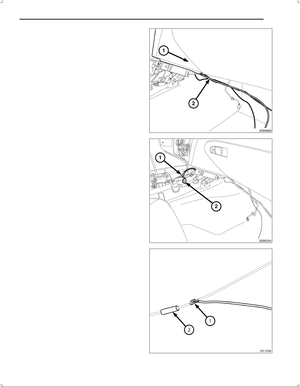
NOTE:Ensurewhenroutingthewirenottodamage
thewireterminals.
47.Feedthebackupcamerawiringharness(2)through
thelowerI/P(1)forconnectingtothe12Vignition
poweroutletwiringharnessandtheTGM.
48.Removeenoughoftheinsulatingtape(1)fromthe
wiresofthe12Vignitionpoweroutletwiringharness
connector(2)tospliceintothetwowires.
11
49.Preparetocrimp/splicethebackupcamerapowerwire
(PK/OR)tothe(DB/PK)ofthe12Vignitionpowerout
letwiringharnessconnectorasfollows:
a.Cutthe12VignitionpoweroutletDB/PKwire.
b.Remove13mm(0.5in.)ofinsulationfromeach
wirethatneedstobespliced.
c.Placeapieceofadhesivelinedheatshrinktubing
(2)ononesideofthewire.Makesurethetubing
willbelongenoughtocoverandsealtheentire
repairarea.
d.Placethestrandsofwireoverlappingeachother
insideofthespliceclip(1).
Nov16,2010K6861117
Page 12
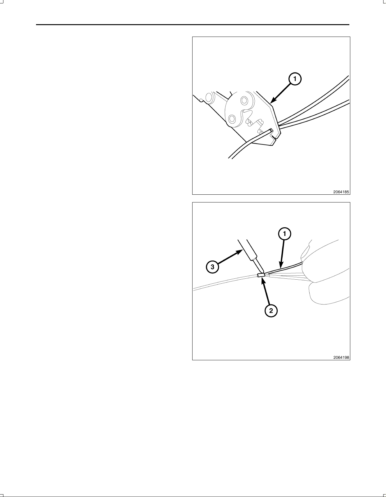
12
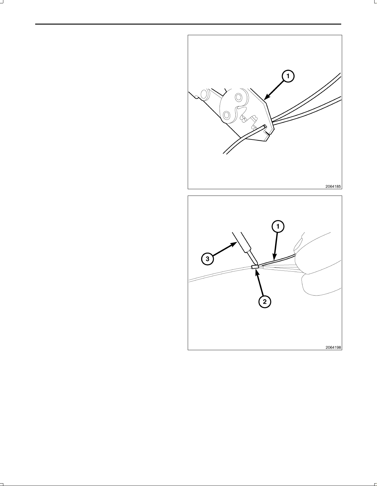
50.Usingcrimpingtool(1),Mopar®p/n05019912AAor
equivalent,crimpthespliceclipandwirestogether.
CAUTION:Donotuseacidcoresolder.
51.Usingasoldertool(3),soldertheconnection(2)to
getherwithrosincoresolder(1).
Nov16,2010K6861117
Page 13
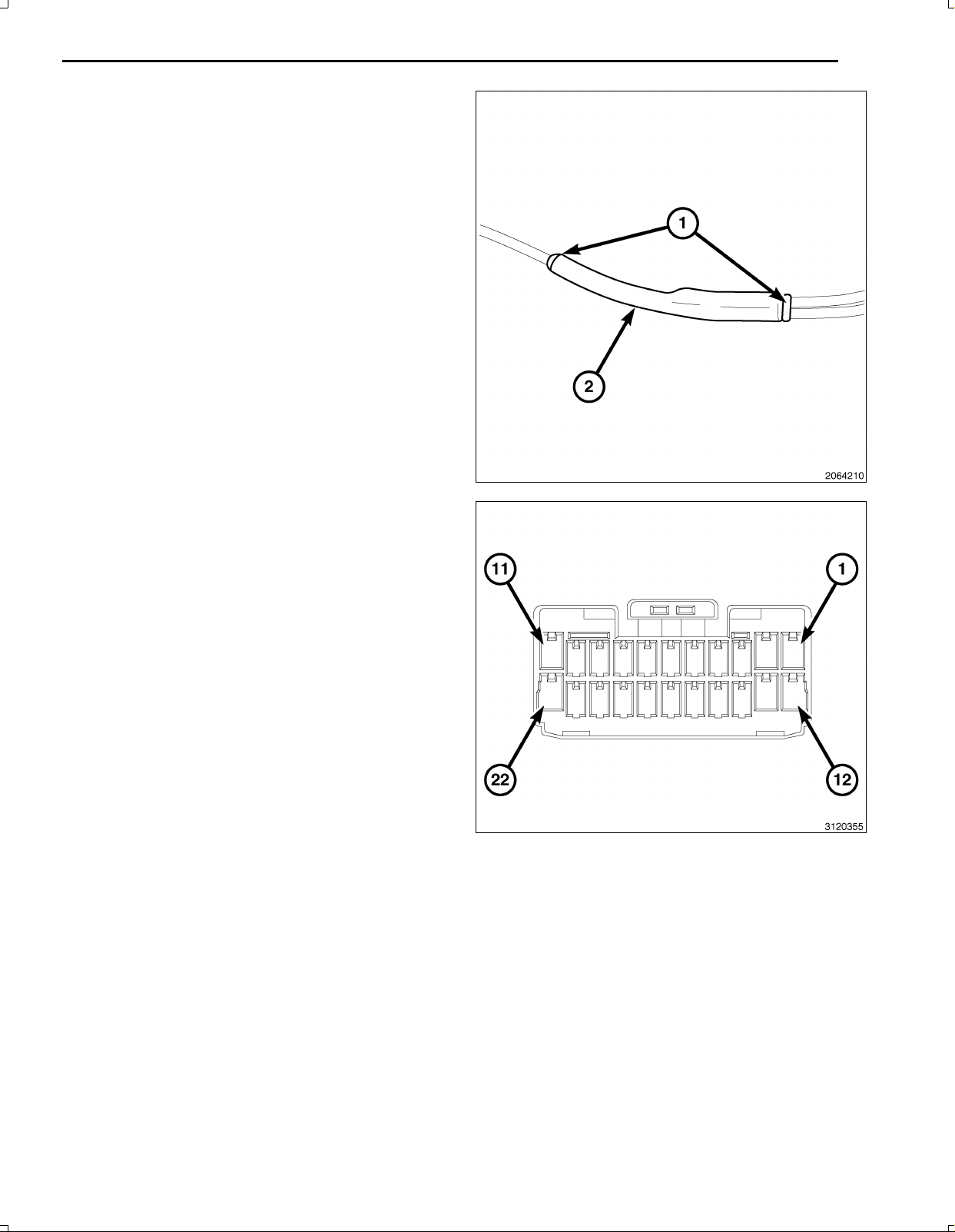
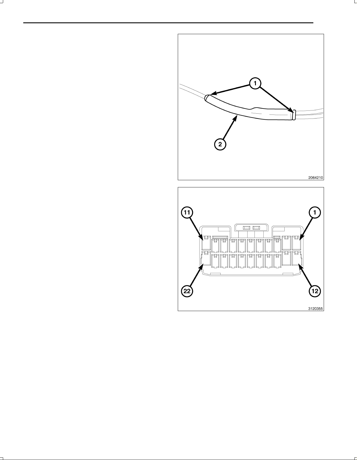
52.Centertheheatshrinktubing(2)overthesolderjoint
andheatusingaheatgun.Heatthejointuntilthetub
ingistightlysealedandsealant(1)comesoutofboth
endsofthetubing.
53.Crimp/splicethebackupcameragroundwire(BK)to
theground(BK)ofthe12Vignitionpoweroutletwiring
harnessconnectorasabove.
13
NOTE:Theremayalreadybea22pinconnectorcon
nectedtotheTGM.Usethatoneanddiscardtheone
suppliedinthekit.
54.BackouttheconnectorwirelockingtabfromtheTGM
harnessconnector3.
55.InsertthecameraharnesswiresintoTGMharness
connector3asfollows:
a.Signalwire(GY/LB)cavity15
b.Returnwire(GY/OR)cavity16
c.Shieldwire(Bare)cavity17
Nov16,2010K6861117
Page 14
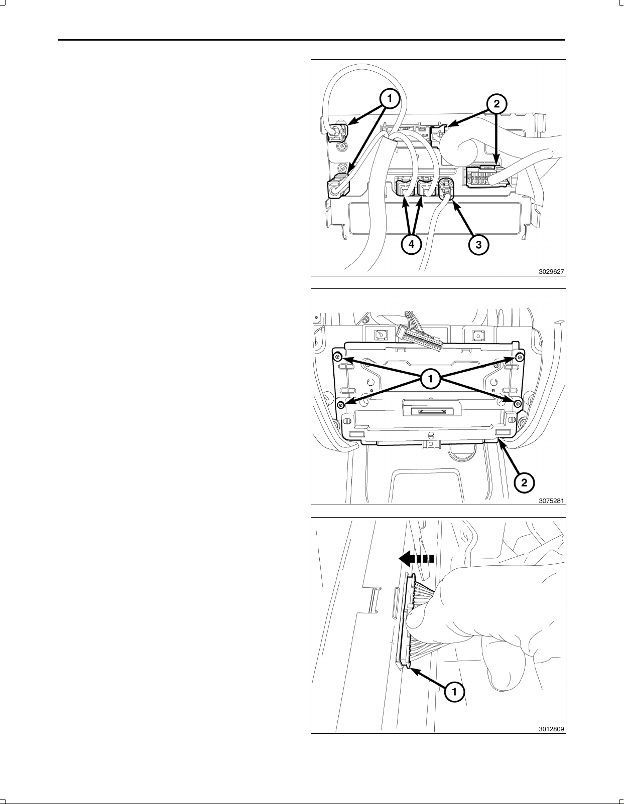
14
56.Connecttheantenna(s)(1),RFHUBandUCIcables
(4),videocable(3)andwiringconnectors(2)tothe
TGM.
NOTE:Makesurethe40wayconnector(1)ofthe
switchbankassemblyispositionedabovethe
TGMforaccesswhenconnectingtheswitchbank
assembly.
57.PositiontheTGM(2)andinstalltheretainingscrews
(1)totheT elematicsGatewayModule(TGM)(2).
58.Connectthe40wayconnector(1)oftheswitchbank
assembly.
Nov16,2010K6861117
Page 15
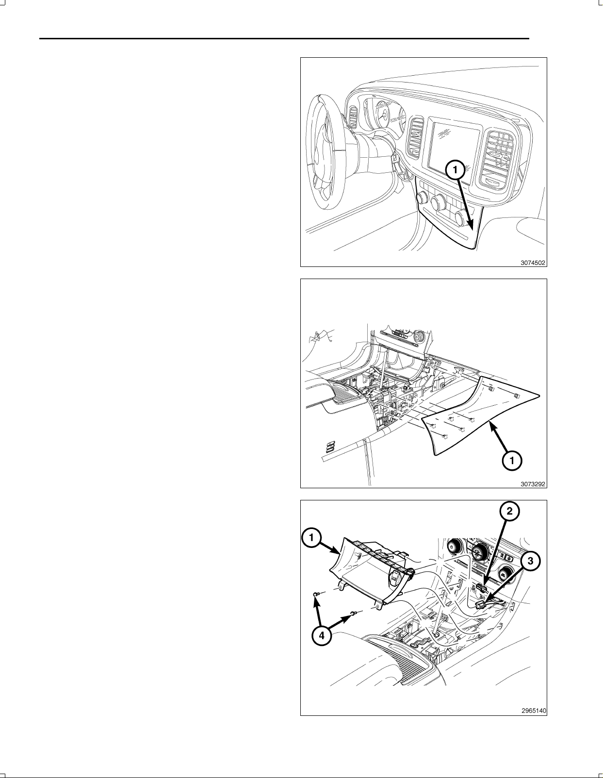
59.Positiontheswitchbankassembly(1)andfirmlypress
intoinstrumentpaneltosecurethesnapretainers.
60.Positionthefloorconsolesidecloseoutpanel(1)and
firmlypressintoplacesecuringthetwosnapretain
ersthatsecurethecloseoutpaneltotheinstrument
panel,andthefivesnapretainersthatsecuretheclose
outpaneltothefloorconsole.
15
61.ConnecttheLED/Lampwiringharness(2)tothestor
agebin(1).
62.Connectthe12Vignitionpoweroutletwiringharness
(3)totherearofthestoragebin(1).
63.Positionthestoragebin(1)andfirmlypushintoplace
securingthetwosnapretainerstothefloorconsole
sidecloseoutpanel.
64.Installthescrews(4)securingthestoragebin(1)to
theconsole.
Nov16,2010K6861117
Page 16
16
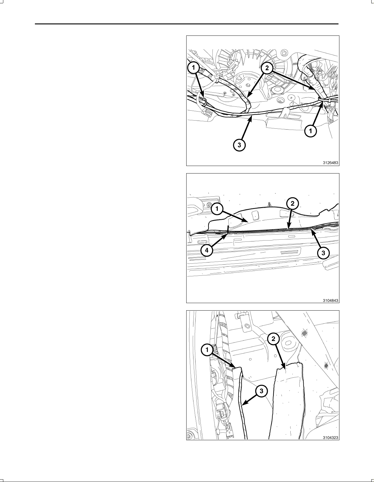
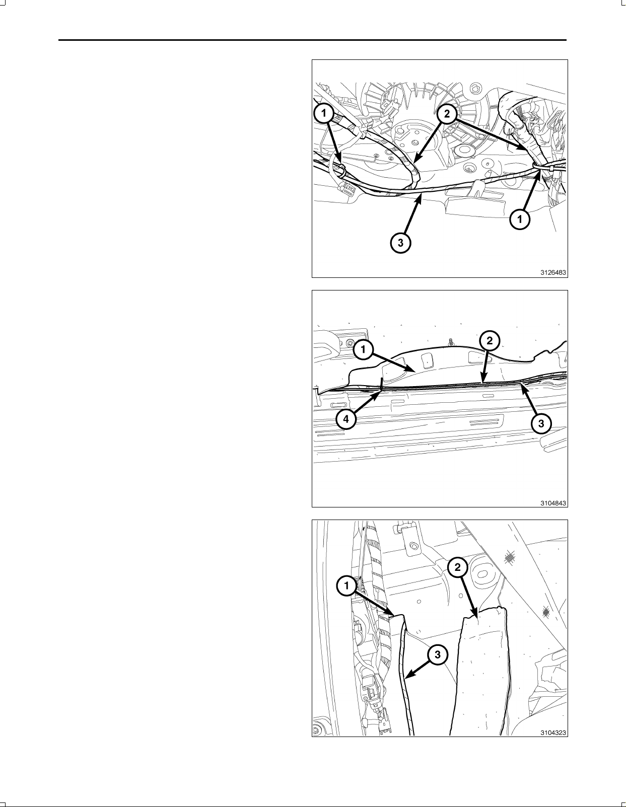
65.Routethebackupcamerawireharness(3)underthe
rightsideoftheI/Pandsecuretothevehicleharness
(2)withtiestraps(1).
66.Routethebackupcamerawireharness(3)underthe
edgeofthecarpet(1)belowtheRHscuffplatesand
theBpillarlowertrim.Attachtothevehiclewiringhar
ness(2)withtiestraps(4)wherenecessary.
67.Feedthebackupcamerawireharness(3)throughthe
bodypanelopening(1)behindtherearseatinsulation
(2)intothetrunkarea.
68.Repositiontheinsulation(2).
Nov16,2010K6861117
Page 17
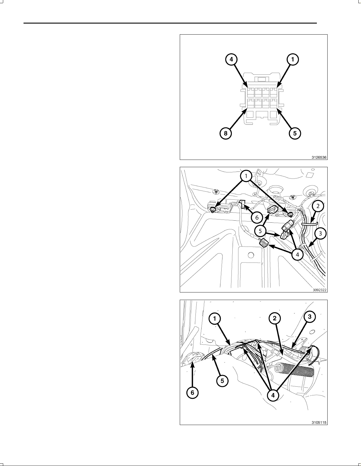
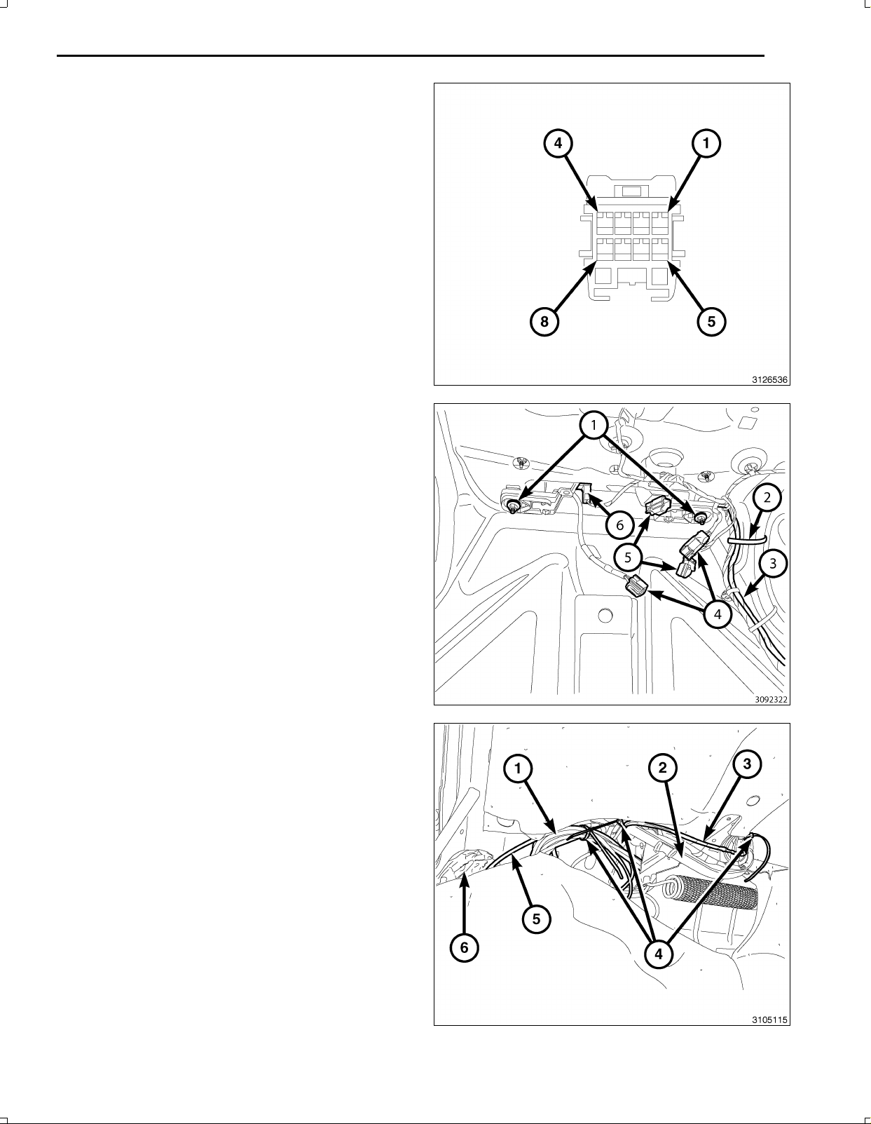
69.Backouttheconnectorterminallockingtabfromthe
backupcameraconnector.
70.Insertthebackupcameraharnesswiresintobackup
cameraconnectorasfollows:
a.12Vignitionpowerwire(PK/OR)cavity2
b.Signalreturnwire(GY/OR)cavity3
c.Signalwire(GY/LB)cavity4
d.Shieldwire(Bare)cavity7
e.Groundwire(BK)cavity8
71.Positionthelampassemblywithbackupcameraand
installtheretainingnuts(1).
72.Connecttheswitchandlampelectricalharnesscon
nectors(5,6).
73.Routethebackupcameraharness(3)withthetrunk
harnessandattachwithtiestraps(2)asnecessary.
74.Connectthebackupcameraconnectors(4)together.
17
75.Routethebackupcameraharness(3)downthetrunk
hinge(2)andattachusingtiestraps(4)asnecessary.
76.Bundletheexcessharness(1)togetherusingatie
strap(4).
77.Tucktheharnessbundle(1)abovethewheelwellse
curingoutofthetrunk/hingemovementareausingtie
straps(4)asnecessary.
78.Tucktheinsulatingmaterial(6)throughtheaccess
holewherethebackupharness(5)comesthrough
thebodypaneltoprotectfromchaffing.
Nov16,2010K6861117
Page 18
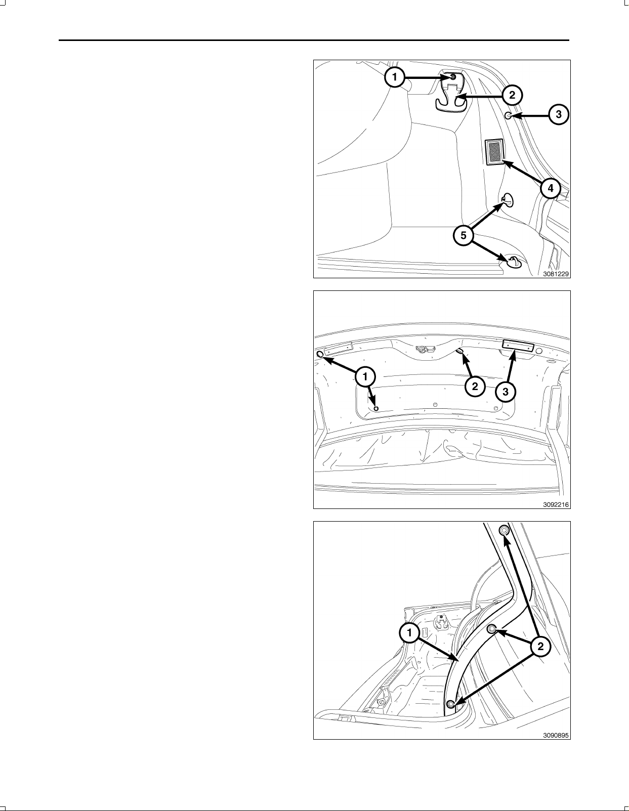
18
79.Installthewheelwellcovertrimasfollows:
a.Positionthewheelwellcoverandconnectthe
trunklamp(4)harnessconnector.
b.Installthecargonetlowerhooks(5).
c.Installthepushinretainer(3)thatsecuresthe
wheelwellcovertrim.
d.Installthecargonethookscrew(1)andupper
cargohook(2).
NOTE:Themanualtrunkreleasehandle(2)mustbe
routedthroughthedecklidtrim.
80.Positionthedecklidtrim,installtheninepushinre
tainers(1)andtwobumperstops(3).tothedecklid.
81.PositiontheRHhingetrim(1)andinstallthepushin
fasteners(2).
Nov16,2010K6861117
Page 19
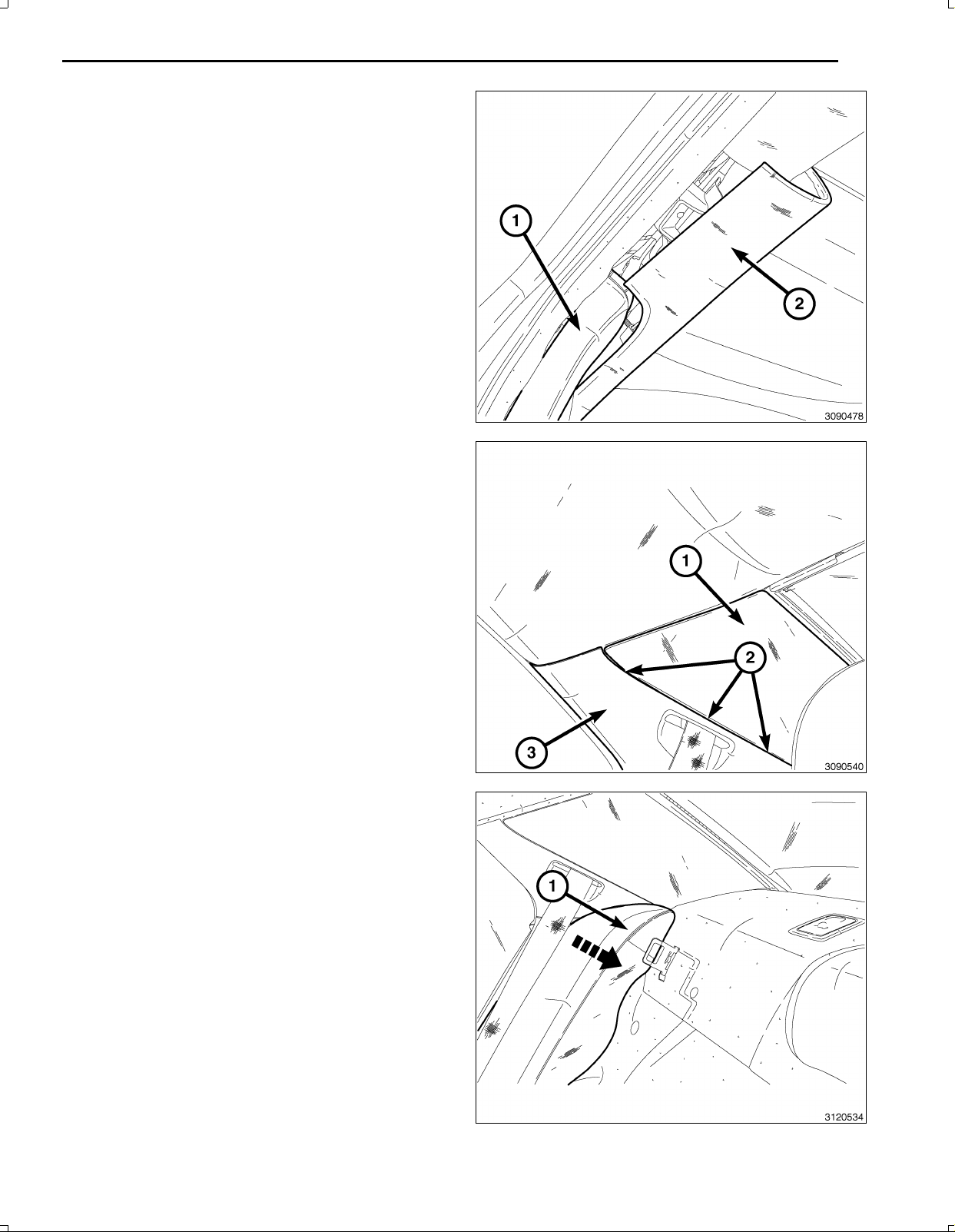
82.Dodgeonly,carefullypositiontheCpillartrim(1),and
fullsecureintoplacewiththepushinfasteners,then
Securethequartertrim(2)withthepushinfasteners.
83.Chrysleronly,removethethreefastenersfromtheup
perportionoftheCpillartrim(1)andinstallonbody
thebody(2).SlidetheCpillartrim(1,3)uptoengage
thethreefasteners(2)andsecurethelowerportionof
theCpillartrim(3)withthepushinfasteners.
19
84.Positiontherearseatbackbolster(1)andpushinto
engagetheupperclipintothebody.
Nov16,2010K6861117
Page 20
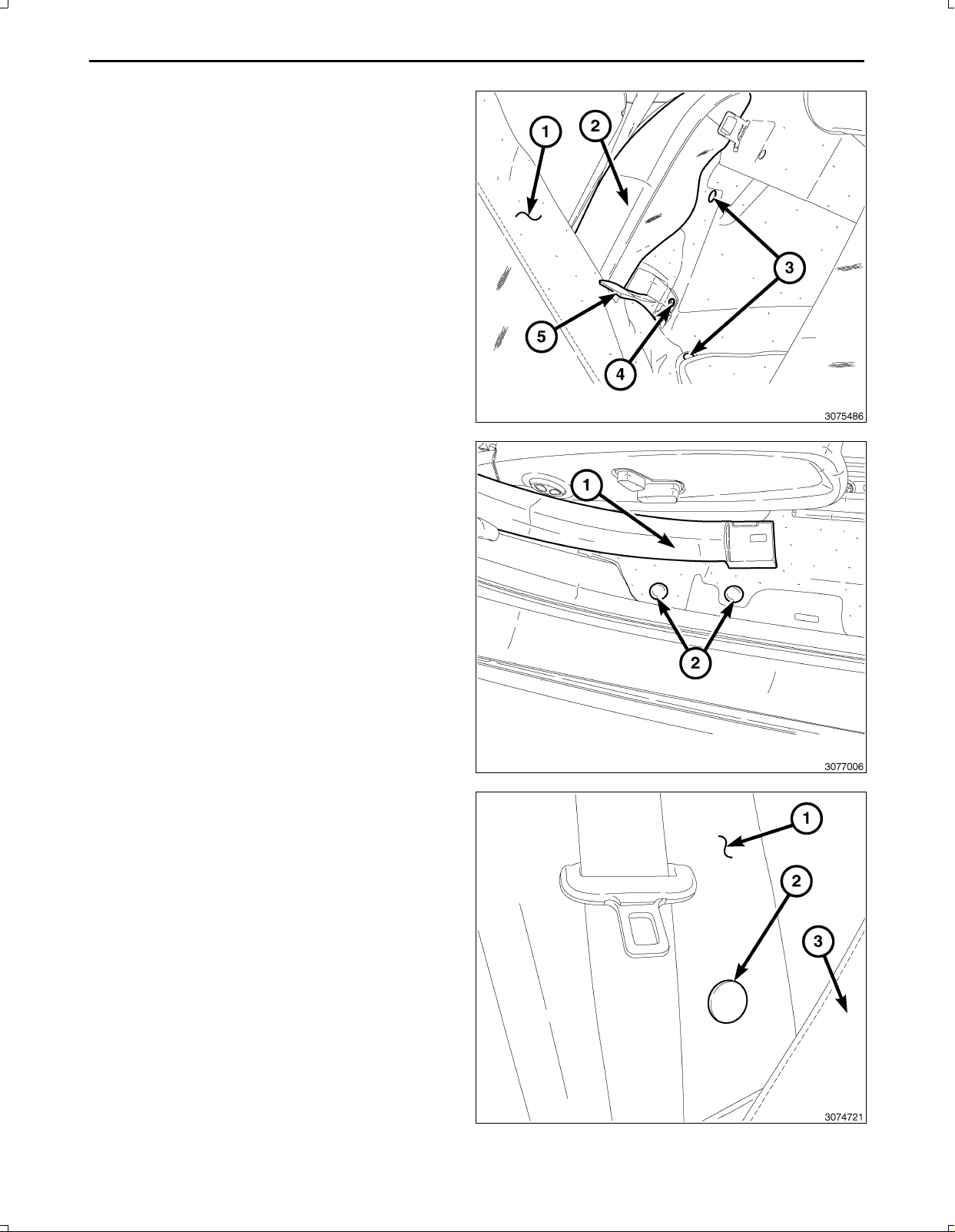
20
85.Positiontheforwardportionofthetrunksidetrimand
installthepushpinfasteners(3)tosecurethetrunk
sidetrim.
86.InstalltheRHrearseatbacksidebolsterbracketbolt
(4).
87.Repositionthecarpettab(5),coveringtherearseat
backsidebolsterbracketretainingbolt(4).
88.Installallcarpetpushpinfasteners(2)alongthefront
andrearscuffplatesandtheRHkickpanelarea.
89.AttachtheRHBpillarlowertrim(1)bysecuringthe
retainerclipsatthelowerportionofthetrim.
90.Ifequipped,installtheRHBpillarlowertrimpanelre
tainingscrewandscrewcover(2).
Nov16,2010K6861117
Page 21
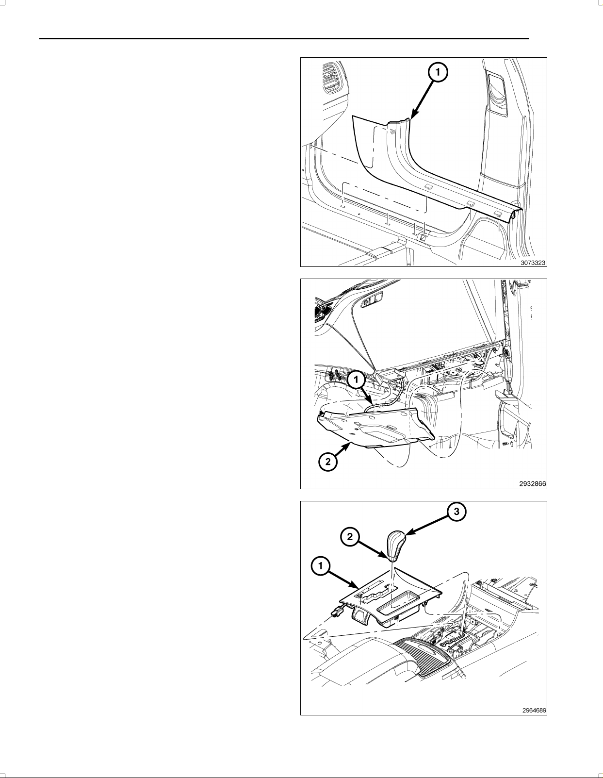
91.InstalltheRHfront(1)andreardoorscuffplatesby
positioningandfirmlyseatingpushpins.
92.ConnecttheLEDharness(1)totheinstrumentpanel
silencer(2)floorlamp.
93.Positiontherightsideinstrumentpanelsilencerand
securetheretainingpushclips.
21
94.Connecttheshifterbezelwiringharnessconnector.
95.Firmlypresstheshifterbezel(1)ontothefloorconsole
tosecurethesnapretainers.
96.Slidetheretainingringovertheshiftershaft(2)and
slidetheshifterknob(3)ontotheshaftandpushdown
intoplaceuntilfullylocked.
97.Connectthebatterynegativecable.
98.Installthesparetirecover/trunkfloorcarpetoverthe
sparetirewell.
Nov16,2010K6861117
Page 22

22
PARKVIEWREARBACKUPCAMERAVEHICLECONFIGURATION
VehicleVINmustbeupdatedwiththesalescodeoftheaddedaccessoryinordertoenablesystemfunctionality.Using
theDealerCONNECTwebsiteandthescantool,completetheprocedurebelow:
1.Logontohttps://dealerconnect.chrysler.com
2.Inthe“VehicleOption”screenunderthe“GlobalClaimsSystem”categoryinthe“Service”tab,enterthevehicleVIN
andaddthesalescodeXAC(ParkViewRearBackUpCamera)asa“DealerInstalledOption”.
3.ConfirmthatthenewsalescodehasbeensuccessfullyaddedtotheVIN.
Withthescantoolconnectedtoboththeinternet(viaEthernetportorwirelessconnection)andthevehicle,followthe
stepsbelow:
4.UsingthescantoolselecttheVEHICLEPREPARATIONandthenselectRESTOREVEHICLECONFIGURATION.
5.FollowthestepbystepinstructionsonthescantooltocompletetheParkViewRearBackUpCameravehicle
configuration.
Nov16,2010K6861117
Page 23
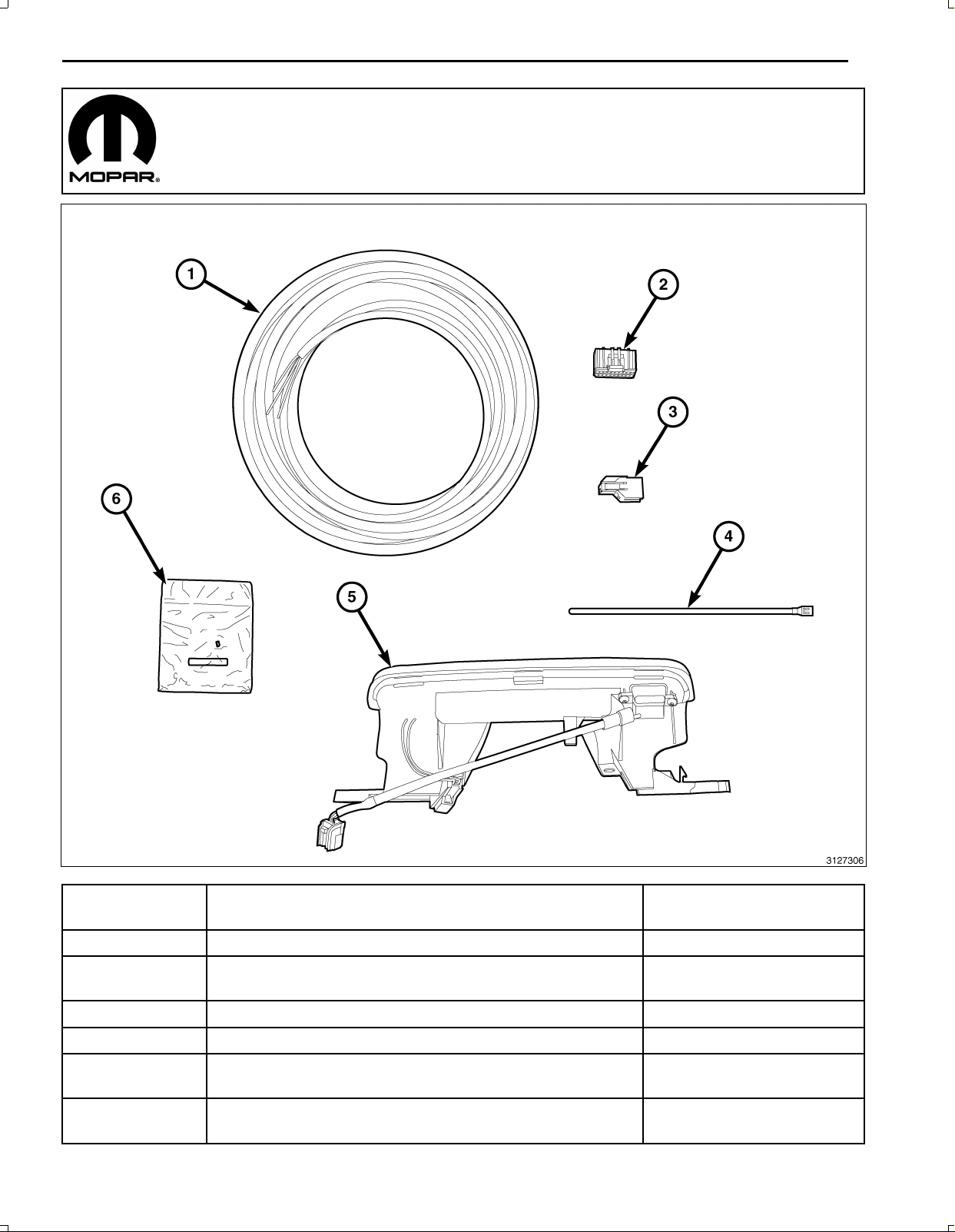
CAMÉRADERECUL
DODGE/CHRYSLER
1
Numérode
légende
1Faisceaudecaméraderecul1
2Faisceaudecaméradereculauconnecteurdemodulede
passerelletélématique(TGM)
3
4Attachesmonousage12
5
6
REMARQUE:TouteslesillustrationssontreliéesàDodgeàmoinsd'indicationcontraire;Chryslerestsimilaire.
Nov16,2010K6861117
Connecteurdecaméraderecul
Feud’arrêtsurélevéavecboutond’ouvertureducoffreet
caméraderecul
Troussed'épissure(comrend2colliersd'épissureetgaine
thermorétractable)
Description
Quantité
1
1
1
1
Page 24
2
Acheminementdufaisceaudelacaméraderecul
ÉTAPESDELAPROCÉDURE:
1.Inclinerlesiègearrièrecôtédroitpouraccéderàlavis
deretenuedupanneauinférieurdepiedmilieu(non
illustré,souslecouvercle,2),selonl'équipement.
2.Selonl'équipement,àl'aided'unebaguettedegar
nissageC4755oul'équivalent,retirerlecouverclede
lavisderetenuedupanneauinférieurdedepiedmi
lieuducôtédroitetretirerlavisderetenue.
Nov16,2010K6861117
Page 25
3.Serrerlefreindestationnement.
4.Mettrelecommutateurd'allumageàlapositionON
(marche),serrerlesfreinsetmettrelelevierde
sélecteurdevitesseàlapositionNeutral(pointmort).
5.Mettrelecommutateurd'allumageàlapositionOff(ar
rêt).
6.Àl'aided'unpetitoutilàlameplateoul'équivalent,
séparerl'anneauderetenue(1)etglisserl'arbre
sélecteurverslebas.
3
7.Retirerlahoussedepneudesecours/moquettedefonddecoffreduogementdepneudesecours.
8.Débrancheretisolerlecâblenégatifdelabatterie.
Nov16,2010K6861117
Page 26
4
9.Àl'aided'unpetitoutildetetypeàfil,localiseret
presserpuisrelâchertoutentirantverslehautsurle
pommeaudesélecteurdevitesse(3).
10.Retirerlepommeaudesélecteurdevitesse(3)etl'an
neauderetenue(2).
11.Àl'aided'unebaguettedegarnissageC4755ou
l'équivalent,souleverentirantdoucemententre
l'encadrementduleviersélecteur(1)etlaconsoleau
plancherpourdégagerlesretenuesencliquetables
quimaintiennentl'encadrement.Nepastireravec
uneforceexcessiveouretirercomplètementà
cetteétape.
12.Débrancherlefaisceaudecâblagedel'encadrement
duleviersélecteuretretirerl'encadrementdulevier
sélecteur(1).
13.Retirerlesdeuxvis(4)quimaintiennentlebacde
rangement(1)àlaconsole.
14.Àl'aided'unebaguettedegarnissageC4755ou
l'équivalent,souleverentirantdoucemententre
l'encadrementduleviersélecteur(1)etl'ouverturedu
panneaudefermeturedelaconsoleauplancherpour
dégagerlesretenuesencliquablesquimaintiennent
lebacderangement(1)àlaconsoleavantetau
panneaudefermeture.
15.Débrancherlefaisceaudecâblage(12)delaprisede
courantdel’allumage3Vdel'arrièredubacderange
ment(1).
16.Débrancherlefaisceaudecâblage(2)defeu/DÉLdu
bacderangement(1)etretirerlebacderangement
dupanneaud'instruments.
REMARQUE:Débrancherseulementleconnecteur
dufaisceaudecâblagedel'ensemblederangée
decommutateursensuivantlesétapesspécifiques
aprèscetteétape.
17.Àl'aided'unebaguettedegarnissageC4755ou
l'équivalent,souleverentirantdoucementl'ensemble
derangéedecommutateurs(1)etlepanneaud'in
strumentspourdégagerlesretenuesencliquablesqui
maintiennentl'ensemblederangéedecommutateurs
(1)aupanneaud'instrumentetl'éloignerdupanneau
d'instrumentpouraccéderauconnecteuretleretirer
ensuivantlesétapessuivantes:
Nov16,2010K6861117
Page 27
ATTENTION:Nejamaiséoignerleconecteurentirant
surlesfils.Ledéfautdesuivrecesdirectivesendom
mageraoubriseralesfilsouleconnecteur.
ATTENTION:Pousserleconnecteur40voieà
l'intérieuravantdemettreenplacel'agrafede
verrouillage.Ledéfautdesuivrecesdirectives
endommageraoubriseral'agrafedeverrouillagedu
connecteur.
18.Poussersurleconnecteur40voie(1)del'ensemble
derangéedecommutateurs.
19.Pousserendouceurverslebassurleconnecteurde
clavettededéverrouillage(1).
5
20.Àl'aided'untournevisoudunebaguettedegar
nissageC4755oul'équivalent(1),tirerendouceur
surlecôtéduconnecteur(2)pourleretirer.
Nov16,2010K6861117
Page 28
6
21.Retirerlesretenues(1)dumoduledepasserelletélé
matique(TGM)(2)etl'éloignersuffisammentpourac
céderauxconnecteursàl'addièreduTGM.
ATTENTION:Lefaitdetirerdirectementsurlecâble
del'antenneetnonsurleconnecteurdeverrouillage
del'antennepeutendommagerlecâbleoularadio.
22.Débrancherl'antenneoulesantennes(1),RFHUBet
lescâblesUCI(4),lesconnecteursdecçablevido(3)
etdecâblage(2)duTGM.
23.RetirerleTGMduvéhicule.
24.Retirerlesretenuesàpressiondusilenlencieuxdu
panneaudebordducôtédroit.
25.DébrancherlefaisceaudeDÉL(1)etretirerlesilen
lencieuxdupanneaudebordducôtédroit(2).
Nov16,2010K6861117
Page 29
26.Ducôtédroit,àl'aided'unebaguettedegarnissage
C4755oul'équivalent,souleverentirantdoucement
entrepanneaudebordetlepanneaudefermeture
latéraldelaconsoleauplancher(1)pourdégagerles
deuxretenuesencliquablesquimaintiennentlepan
neaudefermetureaupaneaudebord.
27.Àl'aided'unebaguettedegarnissage,C4755ou
l'équivalent,souleverentirantdoucementlepanneau
defermeturelatéraldelaconsoleauplancher(1)
etlaconsoleauplancherpourdégagerlesqui
maintiennentlepanneaudefermetureaupaneaude
bordetretirerlepanneau.
28.Àl'aided'unebaguettedegarnissage,C4755ou
l'équivalent,retirerleseuildeportièredeporteavant
côtédroit(1).
29.Retirerleseuildeportièredeportearrièrecôtédroit
delamêmemanièrequepourlaporteavant.
7
REMARQUE:Iln'estpasnécessairederetirerlegar
nissagedepiedmilieu,ilsuffitdeledesserrerpour
accéderetacheminerlefaisceaudecaméraderecul.
30.Àl'avantdugarnissagedepiedmilieu,éloignervers
lesiègepourdégagerlesagrafesderetenue.Répéter
àl'arrièregarnissagedepiedmilieupourdesserrerla
partieinférieuredugarnissage.
31.Retirertouteslesattachesàpoussoirdelamoquette
lelongdel'avantetdel'arrièredesseuilsdeportière
etdelazonedeplaquedegardeducôtédroit.
Nov16,2010K6861117
Page 30
8
32.Tirerledossierdesiègeducôtédroit(1)versl'avant,
pourexposerlecoffre.
33.Derrièrelesiègearrièrecôtédroit,tirerl'ongletde
moquette(5)verslehaut,pourexposerleboulonde
retenuedusupportderembourragelatéraldudossier
desiègearrière(4).
34.Retirerboulonderetenuedusupportderembourrage
latéraldudossierdesiègearrière(4).
35.Retirerlesattachesàpoussoir(3)quimaintiennentle
garnissagelatéralducoffre.
36.Àl'aided'unebaguettedegarnissageC4755(2)ou
l'équivalent,pousserverslebasentrelatablettear
rièreetlerembourragearrièredesiègearrièrecôté
droit(1)pourdégagerl'agrafederetenueettirersur
lerembourragearrièredesiègearrière(1)pourlere
tirer.
37.DodgeseulementÀl'aided'unebaguettede
garnissageC4755oul'équivalent,souleveren
tirantdoucementlagarnituredecustode(2)pourla
dessserrersuffisammentpourretirerlagarniturede
piedarrière(1).
Nov16,2010K6861117
Page 31
38.ChryslerseulementÀl'aided'unebaguettede
garnissageC4755oul'équivalent,souleverentirant
doucementlagarnituredecustode(1)àtroispoints
(2)pourladessserrersuffisammentpourretirerla
garnituredepiedarrière(3).
39.Àl'aided'unebaguettedegarnissageC4755ou
l'équivalent,souleverentirantdoucementlagarniture
depiedarrière(1)versl'intérieurpourdesserrerles
attachesàpoussoir,puistirerversl'avantetversle
baspourlaretirerduvéhicule.
40.Replierl'isolateur(2)pourexposerlazoned'achem
inementdufaisceaudecâblage.
9
41.Ouvrirlecoffreduvéhicule.
42.Retirerlesattachesàpoussoirdegarnissagede
charnièresducôtédroit(2)etretirerlesgarnissage
decharnières(1).
Nov16,2010K6861117
Page 32
10
REMARQUE:Lapoignéededéverrouillagemanueldu
coffre(2)doitêtreacheminéeàtraverslagarniturede
couvercledecoffre.
43.Retirerlesdeuxbutéesdeparechocs(3)etlesneuf
attachesàpoussoirducouvercledecoffreetretirer
lagarnitudedecouvercledecoffreducouverclede
coffre.
44.Retirerlagarnituredehoussedelogementderouede
lafaçonsuivante:
a.Surlecôtédroit,retirerlavisducrochetdefilet
àbagages(1)etlecrochetàbagagessupérieur
(2).
b.Surlecôtédroit,retirerl'attacheàpoussoir(3)qui
maintientlagarnitureducouvercledelogement
deroue.
c.Surlecôtédroit,retirerlescrochetsinférieursde
filetàbagages(5).
d.Souleveravecsoinlahoussedelogementde
rouepourdébrancherleconnecteurdefaisceau
(4)delalampeducoffreetretirerlagarniturede
houssedelogementderoue.
45.Débrancherlesconnecteursdefaisceauélectriquede
commutateuretdelampe(2,3).
REMARQUE:Aprèsavoirretirerlesécrous(1)on
trouvelesongletsderetenueàcôtédesgoujons
quel'ondoitpousserversl'intérieurpourretirer
l'ensembledelampe.
46.Retirerlesécrousd'ensembledelampe(1)etretirer
l'ensembledelampeduvéhicule.
Nov16,2010K6861117
Page 33
REMARQUE:Enacheminantlecâble,s'assurerdene
pasendommagerlesbornesdecâblage.
47.Acheminerlefaisceaudecâblagedelacamérade
recul(2)àtraverslapartieinférieuredupanneaude
bord(1)pourleconnecteurdufaisceaudecâblagede
laprisedecourantdel'allumage12Vetlemodulede
passerelletélématique(TGM).
48.Retirersuffisammentderubanisolant(1)desfilsdu
connecteur(12)dufaisceaudecâblagedelaprise
decourantdel'allumage2Vpourlesépisserdansles
deuxfils.
11
49.Préraperàsertir/épisserlefild'alimentationdela
caméraderecul(PK/OR)au(DB/PK)duconnecteur
dufaisceaudecâblagedelaprisedecourantde
l'allumage12Vdelafaçonsuivante:
a.CouperlefilDB/PKdelaprisedecourantdel'al
lumage12V.
b.Déposer13mm(0.5po)d'isolantdechaquefilqui
doitêtreépissé.
c.Placerunmorceaudegainethermorétractable
doubléeadhésive(2)suruncôtédufil.S'assurer
quelagaineseraassezlonguepourcovriret
scellertoutelazonederéparation.
d.Placerlesbrinsdecâblequisechevauchentàl'in
térieurdel'agrafed'épissage(1).
Nov16,2010K6861117
Page 34
12
50.Àl'aided'unoutilàsertir(1),Mopar®n/p05019912AA
oul'équivalent,sertirl'agrafeépisséeetlesfilsensem
ble.
ATTENTION:NEPASUTILISERDEMÉTALD'APPORT
ÀÂMEDÉCAPANTEENRÉSINE.
51.Àl'aided'unoutilàsouder(3),souderlaconnexion
(2)àlasoudureànoyauderésine(1).
Nov16,2010K6861117
Page 35
52.Centrerletubethermorétrécissable(2)pardessusle
jointdesoudureetchaufferàl'aided'unpistoletther
mique.Chaufferlejointjusqu'àcequeletubesoitpar
faitementscelléetquel'enduitd'étanchéité(1)sorte
parlesdeuxextrémitésdutube.
53.Souder/épisserlefildemasse(BK)delacaméra
dereculàlamasse(BK)connecteurdufaisceau
decâblagedelaprisedecourantdel'allumage12V
commecidessus.
13
REMARQUE:Ilpeutyavoirunconnecteuràbroche22
connectéauTGM.Utiliserceluicietmettreaurebut
celuifournidanslatrousse.
54.Désserrerlalanguettedeblocagedufildeconnecteur
duconnecteurdefaisceau3duTGM.
55.Insérerlesfilsdufaisceaudelacaméradansle
connecteurdefaisceaudu3TGMtelqu'indiqué
cidessous:
a.Fildesignal(GY/LB)cavité15
b.Filderetour(GY/OR)cavité16
c.Filblindé(Nu)cavité17
Nov16,2010K6861117
Page 36
14
56.Brancherlesantennescâbles(1),RFHUBetUCIdes
antennes(4),lecâblevidéo(3)etlesconnecteursde
fil(2)auTGM.
REMARQUE:S'assurerqueleconnecteur(40)1voie
del'ensemblederangéedecommutatuersestposi
tionnéaudessusduTGMpouryaccéderlorsdela
posedel'ensemblederangéedecommutatuers.
57.PositionnerleTGM(2)etposerlesvisderetenue(1)
aumoduledepasserelletélématique(TGM)(2).
58.Brancherleconnecteur(40)1vieàl'ensemblede
rangéedecommutateurs.
Nov16,2010K6861117
Page 37
59.Positionnerl'ensemblederangéedecommutateurs
(1)etlepresserfermementdansletableaudebord
pourassujettirlesattachesàpoussoir.
60.Positionnerlepanneaudefermeturelatéraledela
consoleauplancher(1)etppresserfermementen
placepourassujettirlesattachesàpoussoirquir
maintiennentlepanneaudefermeturelatéraleàla
consoleauplancher.
15
61.BrancherlefaisceaudecçablagedeDÉL/lampe(2)
aubacderangement(1).
62.Brancherlefaisceaudecâblage12deprisede
courantdel'allumage3Vàl'arrièredubacder
angement(1).
63.Positionnerlebacderangement(1)etlepousserfer
mementenplacepourassujettirlesdeuxattachesà
poussoiraupanneaudefermeturelatéraldelacon
soleauplancher.
64.Poserlesvis(4)quimaintiennentlebacderangement
(1)àlaconsole.
Nov16,2010K6861117
Page 38
16
65.Acheminerlefaisceaudecâblage(3)delacamérade
reculsouslecôtédroitdutableaudebordetassujettir
lefaisceau(2)auvéhiculeavecdesserrecâbles(1).
66.Acheminerlefaisceaudecâblage(3)delacamérade
reculsousleborddelamoquette(1)souslesseuilsde
portièreducôtédroitetsouslajanteinférieureumon
tantB.Attacheraufaisceaudecâblage(2)duvéhicule
avecdesserrecâbles(4)laoùc'estnécessaire.
67.Acheminerlefaisceaudecâblage(3)delacaméraà
traversl'ouverturedupanneaudecarrosserie(1)der
rièrel'isolationdusiègearrière(2)danslecoffre.
68.Repositionnerl'isolation(2).
Nov16,2010K6861117
Page 39
69.Dégagerlalanguettedeblocageduconnecteurdu
connecteurdelacaméraderecul.
70.Insérerlescâblesdufaisceaudelacaméraderecul
dansleconnecteurdelacaméradereculdelafaçon
suivante:
a.Câbled’alimentationd’allumage12V(PK/OR)
cavité2
b.Fildeclignotant(GY/OR)cavité3
c.Fildesignal(GY/LB)cavité4
d.Filblindé(Nu)cavité7
e.Fildemasse(BK)cavité8
71.Positionnerl'ensembledelampeenligneavecla
caméradereculetposerlesécoursderetenue(1).
72.Brancherlesconnecteurs(5,6)defaisceauélectrique
decommutateuretdelampe.
73.Acheminerlefaisceau(3)delacaméradereculavec
lefaisceaudecoffreetattacheravecdesserrecâbles
(2)aubesoin.
74.Brancherlesconnecteurs(4)delacaméraderecul
ensemble.
17
75.Acheminerlefaisceau(3)delacaméradereculvers
lebasàlacharnièreducoffre(2)etattacheràl'aide
deserrecâbles(4)aubesoin.
76.Attacherl'excédentdefaisceau(1)àl'aidedeserre
câbles(4).
77.Placerleballotdefaisceau(1)audessusdulogemen
deroueetl'assujettiràl'écartdelazonedemouve
mentducoffre/delacharnièreàl'aidedeserrecâbles
(4)aubesoin.
78.Placerlematérielisolant(6)àtraversletroud'accès
oùlefaisceauderecul(5)passeparlepanneaude
carrosseriepouréviterl'effilochage.
Nov16,2010K6861117
Page 40
18
79.Poserlagarnituredecouvercledelogementderoue
commesuit:
a.Positionnerlecouvercledelogementderoueet
brancherleconnecteurdefaisceaudelalampe
(4)decoffre.
b.Poserlescrochetsinférieurs(5)dufiletà
bagages.
c.Poserl'attacheàpoussoir(3)quimaintientlagar
nitureducouvercledelogementderoue.
d.Poserlavisducrochet(1)dufiletàbagagesetle
crochetsupérieur(2)debagages.
REMARQUE:Lapoignéededéverrouillagemanueldu
coffre(2)doitêtreacheminéeàtraverslagarniturede
couvercledecoffre.
80.Positionnerlagarnituredecouvercledecoffre,poser
lesneufattachesàpoussoir(1)etlesdeuxbutéesde
parechocs(3).aucouvercleducoffre.
81.Positionnerlagarnituredecharnière(1)ducôtédroit
etposerlesattachesàpoussoir(2).
Nov16,2010K6861117
Page 41
82.Dodgeseulementpositionneravecsoinlagarniture
dumontantC(1),bienassujettirenplaceàl'aided'at
tachesàoussoirpuisassujettirlagarnituredecustode
(2)àl'aiderd'attachesàpoussoir.
83.Chryslerseulementretirerlestroisattachesdela
partiesupérieuredelagarnituredumontantC(1)et
posersurlacarrosserie(2).Glisserlagarniturede
montantC(1,3)verslehautetengagerlestroisat
taches(2)etassujettirlapartieinférieuredelagarni
turedemontantC(3)àl'aided'attachesàpoussoir.
19
84.Positionnerlerembourragededossierdusiège
arrière(1)etlepousserversl'intérieurourengager
l'agrafesupérieuredanslacarrosserie.
Nov16,2010K6861117
Page 42
20
85.Positionnerlapartieavantdelagarniturelatéralede
coffreetposerlesfixationsàemboîter(3)pourassu
jettirlagarniturelatéraledecoffre.
86.Poserleboulondesupportrembourrage(4)de
dossierdesiègearrièreducôtédroit.
87.Repositionnerlalanguettedelamoquette(5),quicou
vreleboulondesoutien(4)desupportderembour
ragedesiègearrière.
88.Posertouteslesfixationsàemboîter(2)demoquette
lelongdel'avantetdel'arrièredesseuilsdeporteet
delazonedesplaquesdegardeducôtédroit.
89.Attacherlagarnitureinférieuredepiedmilieu(1)en
assujettissantlesagrafesderetenueàlapartiein
férieuredelagarniture.
90.Selonl'équipement,poserlavisetlecouvrevisde
retenuedelagarnitureinférieuredepiedmilieu(2).
Nov16,2010K6861117
Page 43
91.Poserlesseuilsdeporteavant(1)etarrièreenpo
sitionnantetenengageantfermementlesfixationsà
emboîter.
92.BrancherlefaisceaudeDÉL(1)àlalampede
plancher(2)del'insonorisantdetableaudebord.
93.Positionnerl'insonorisantdutableaudebordducôté
droitetassujettirlesattachesàpoussoirderetenue.
21
94.Brancherleconnecteurdefaisceaudecâblagede
l'encadrementduleviersélecteur.
95.Presserfermementl'encadrementduleviersélecteur
(1)surlaconsoleauplancherpourassujettirles
retenuesencliquables.
96.Glisserl'anneauderetenuesurl'arbresélecteur(2)et
glisserlepommeaudesélecteurdevitesse(3)surle
sélecteuretpousserenplaceverslebasjusqu'àce
qu'ilsoitbienengagé.
97.Brancherlecâblenégatifdelabatterie.
98.Poserlahoussedupneudesecoursetmoquettedu
coffresurlelogementdupneudesecours.
Nov16,2010K6861117
Page 44

22
CONFIGURATIONDELACAMÉRADERECULPOURLAVUEDESTATIONNEMENTARRIÈRE
LeNIVdoitêtremisàjouraveclecodecommercialdel'accessoireajoutéafind'autoriserlafonctionnalitédusystème.
Àl'aidedusiteWebDealerCONNECTetd'unanalyseur,compléterlaprocédurecidessous:
1.Seconnecteràhttps://dealerconnect.chrysler.com.
2.Àl'écran«Optionvéhicule»souslacatégorie«Systèmeglobaldetraitementdesdemandesderèglement»dans
l'onglet«Service»,entrerleNIVduvéhiculeetajouterandlecodedeventeXAC(Caméradestationnementà
reculons)comme«Optiond'installationchezleconcessionnaire».
3.ConfirmerquelenouveaucodedeventeaétécorrectementajoutéauNIV.
Àl'aided'unanalyseurbrancheràl'Internet(viaunportÉthernetouuneconnexionsansfil)ETauvéhicule,suivreles
étapescidessous:
4.Àl'aidedel'analyseur,choisissezPRÉPARATIONDUVÉHICULEpuissélectionnerRESTAURATINDELACON
FIGURATIONDUVÉHICULE.
5.Suivrelesinstructionsétapeparétapesurl'analyseurpourcompléterlaconfigurationdelacaméradestationnement
àreculonssurlevéhicule.
Nov16,2010K6861117
Page 45
CÁMARATRASERA
DODGE/CHRYSLER
1
Elemento
Relaciónnominal
deaspectode
anchodepantalla
1
Relaciónnominal
deaspectode
anchodepantalla
2
Relaciónnominal
deaspectode
anchodepantalla
3
Nov16,2010K6861117
MazodecablesdelacámarademarchaatrásRelaciónnominaldeaspecto
Mazodecablesdelacámarademarchaatrásalconectordel
módulodepasarelatelemática(TGM)
Conectordelacámarademarchaatrás
DESCRIPCIONCantidad
deanchodepantalla1
Relaciónnominaldeaspecto
deanchodepantalla1
Relaciónnominaldeaspecto
deanchodepantalla1
Page 46
2
Elemento
Relaciónnominal
deaspectode
anchodepantalla
4
Relaciónnominal
deaspectode
anchodepantalla
5
Relaciónnominal
deaspectode
anchodepantalla
6
NOTA:TodaslasvistassondeDodge,salvodondeseindica.LasdeChryslersonsimilares.
BridasRelaciónnominaldeaspecto
Luzdefrenosuperiorconbotóndeaperturadelmaleteroy
cámarademarchaatrás
Kitdeempalmes(incluye2collaresdeempalmesyuntubo
decontracción)
DESCRIPCIONCantidad
deanchodepantalla12
Relaciónnominaldeaspecto
deanchodepantalla1
Relaciónnominaldeaspecto
deanchodepantalla1
Recorridodelmazodecablesdelacámarademarchaatrás
PASOSDELPROCEDIMIENTO:
1.Inclineelrespaldodelasientoderechoparaacceder
altornillodefijacióndelpanelinferiordelmontanteB
(noaparece,bajolacubierta,2),siestáequipado.
2.Siestáequipado,conunavarillaC4755oequiva
lente,retirelacubiertadeltornillodelrevestimiento
inferiordelmontanteBderechoyretireeltornillode
fijación.
Nov16,2010K6861117
Page 47
3.Apliqueelfrenodeestacionamiento.
4.ColoqueelcontactoenposiciónOn,apliquelosfrenos
deservicioycoloqueelselectordemarchasenposi
ciónNeutral.
5.ColoqueelcontactoenposiciónOff.
6.Conunaherramientapequeñadepuntaplanao
equivalente,separeelanillodefijación(1)ydeslice
elejedelcambio.
3
7.Retirelacubiertadeneumáticoderepuesto/alfombradelsuelodelmaleteroqueestáencimadelhuecodel
neumáticoderepuesto.
8.Desconecteyaísleelcablenegativodelabatería.
Nov16,2010K6861117
Page 48
4
9.Conunalambrefinooherramientasimilar,localicey
presioneelliberadormientrastiradelpomodelcam
biador(3).
10.Retireelpomodelcambiador(3)yelanillodereten
ción(2).
11.ConunavarillaC4755oequivalente,hagapalanca
suavementeentreelembellecedordelapalanca(1)
ylaconsoladesueloparasoltarlosretenedoresque
fijanelpaneldeinstrumentos.Notireconexcesiva
fuerzaniloretireporcompletodemomento.
12.Desconecteelmazodecablesdelembellecedorde
lapalancadelcambioyretírelo(1).
13.Retirelosdostornillos(4)quefijanelcompartimento
dealmacenamiento(1)alaconsola.
14.ConunavarillaC4755oequivalente,hagapalanca
suavementeentreelcompartimentodealmace
namiento(1)ylaconsoladelsueloexteriorpara
soltarlosdosretenedoresquefijanelcompartimento
dealmacenamiento(1)alaconsoladelanteray
cierreelpanel.
15.Desconecteelmazodecablesdealimentacióndeen
cendidode12V(3)delaparteposteriordelcomparti
mentodealmacenamiento(1).
16.DesconecteelmazodecablesdeLED/luces(2)del
compartimentodealmacenamiento(1)yretireelcom
partimentodealmacenamientodelP/I.
NOTA:Desconecteúnicamenteelconectordelmazo
decablesdelgrupodeconmutadoresrealizandoel
siguienteprocedimiento.
17.ConunavarillaC4755oequivalente,hagapalanca
suavementeentreelgrupodeconmutadores(1)yel
paneldeinstrumentosparasoltarlosretenedoresque
fijanelgrupodeconmutadores(1)alpaneldeinstru
mentosytiredeélparaaccederalconectormediante
elsiguienteprocedimiento:
Nov16,2010K6861117
Page 49
PRECAUCIÓN:Notiredelconectorporloscables.Si
nosigueestasinstruccionespuededañaroromper
loscablesy/oelconector.
PRECAUCIÓN:Tiredelconectorde40víasantesde
presionarelclipdebloqueo.Sinosigueestasinstruc
cionespuededañaroromperelclipdebloqueodel
conector.
18.Presioneelconectorde40vías(1)enelgrupode
conmutadores.
19.Presionesuavementeelcierredelconector(1).
5
20.ConundestornilladorpequeñoounavarillaC4755
oequivalente(1),hagapalancasuavementeunlado
delconector(2)pararetirar.
Nov16,2010K6861117
Page 50
6
21.Retireloselementosdefijación(1)delmódulode
pasarelatelemática(TGM)(2)ytirelosuficiente
comoparaaccederalosconectoresenlaparte
posteriordelTGM.
PRECAUCIÓN:Sisesacaelcabledelaantenarecto
haciafueradelaradiosinhacerlopropioconel
conectordetrabadelaantenapodríadañarseel
cableolaradio.
22.Desconectelaantena(s)(1),loscablesdeRFHUBy
UCI(4),elcabledevídeo(3)ylosconectoresdelos
cables(2)delTGM.
23.RetireelTGMdelvehículo.
24.Retireloselementosdefijacióndelsilenciadordel
paneldeinstrumentosdelladoderecho.
25.DesconecteelarnésdeLED(1)yretireelsilenciador
delpaneldeinstrumentosdelladoderecho(2).
Nov16,2010K6861117
Page 51
26.EnelladoderechoyconunavarillaC4755oequiva
lente,hagapalancasuavementeentreelpaneldein
strumentosyelpanelexteriordelaconsoladesuelo
(1)parasoltarlosdosretenedoresquefijanelpanel
exterioralpaneldeinstrumentos.
27.ConunavarillaC4755oequivalente,hagapalanca
suavementeentreelpanelexteriordelaconsoladel
suelo(1)ylaconsoladelsueloparasoltarloscinco
retenedoresquefijanelpanelexterioralaconsoladel
sueloyretireelpanel.
28.UtiliceunavarillaC4755oequivalenteyretireel
limpiabarrosdelapuertadelanteraderecha(1).
29.Retireellimpiabarrosdelapuertatraseraderechade
lamismaformaquelapuertadelantera.
7
NOTA:Noesnecesarioretirarelrevestimientodel
montanteB,sinoaflojarparaaccederalrecorridode
loscablesdelmazodelacámarademarchaatrás.
30.Enlapartedelanteradelrevestimientoinferiordel
montanteBderecho,tirehaciaarribadelasientopara
soltarlosclipsderetención.Repitaelprocedimiento
enlaparteposteriordelrevestimientodelmontante
Bparasoltarlaparteinferiordelrevestimiento.
31.Retiretodoslosdispositivosdefijacióndepresiónde
latapiceríadeloslimpiabarrosdelanteroytraseroy
delazonadelzócaloinferiorderecho.
Nov16,2010K6861117
Page 52
8
32.Tiredelrespaldodelasientotraseroderecho(1)para
accederalcompartimientodeequipaje.
33.Detrásdelasientotraseroderecho,tiredelatapicería
(5),paraaccederalpernodefijacióndelrefuerzodel
respaldodelasientotrasero(4).
34.Retireelpernodefijacióndelrefuerzodelrespaldo
delasientotraseroderecho(4).
35.Retirelosdispositivosdefijacióndepresión(3)que
fijanelrevestimientolateraldelmaletero.
36.ConunavarillaC4755(2)oequivalente,hagapre
siónentreelanaqueltraseroyelrefuerzodelrespaldo
delasientotraseroderecho(1)parasoltarelclipdefi
jaciónytiredelperno(1)pararetirarlo.
37.EnelcasodeDodgeúnicamente,utiliceunavarilla
C4755oequivalente,extraigaconcuidadoelreves
timiento(2)losuficientepararetirarelrevestimiento
delmontanteC(1).
Nov16,2010K6861117
Page 53
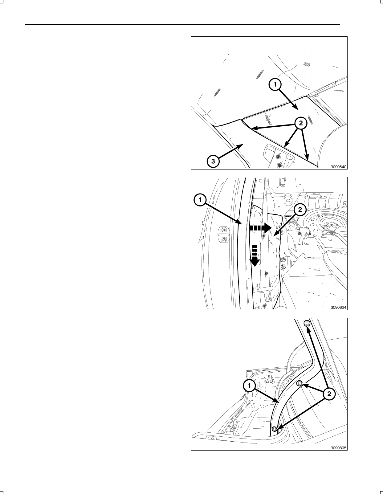
38.EnelcasodeChryslerúnicamente,utiliceunavarilla
C4755oequivalente,extraigaconcuidadoelreves
timiento(1)entrespuntos(2)losuficientepararetirar
elrevestimientodelmontanteC(3).
39.ConunavarillaC4755oequivalente,hagapalanca
suavementeenelrevestimientodelmontanteC(1)
haciadentroparaaflojarloselementosderetención
depresión,ytirehaciaabajoparasoltarlodel
vehículo.
40.Dobleelaislante(2)paraaccederalazonaderecor
ridodelmazodecables.
9
41.Abraelmaleterodelvehículo.
42.Retirelosdispositivosdefijacióndelrevestimientode
labisagraderecha(2)yretireelrevestimientodela
bisagra(1).
Nov16,2010K6861117
Page 54

10
NOTA:Eltiradordeldesbloqueodelmaleteromanual
(2)sedebedirigirhaciaelrevestimientodelatapadel
maletero.
43.Retirelosdostopesdelparachoques(3)ylosnueve
elementosdefijación(1)delatapadelmaleteroyre
tireelrevestimientodelatapadelmaletero.
44.Retireelrevestimientodelacubiertadelhuecodela
ruedadelasiguienteforma:
a.Enelladoderecho,retireeltornillodelganchode
lareddecarga(1)yelganchodecargasuperior
(2).
b.Enelladoderecho,retireelretenedor(3)quefija
elrevestimientodelatapadelhuecodelarueda.
c.Enelladoderecho,retireellosganchosinferiores
delareddecarga(5).
d.Concuidado,tirehaciaatrásdelacubiertadel
huecodelaruedaparadesconectarelmazode
cables(4)delaluzdelmaleteroyretireelreves
timientodelacubiertadelhuecodelarueda.
45.Desconectelosconectoresdelmazodecablesdel
conmutadorylaluz(2,3).
NOTA:Despuésderetirarlastuercas(1)verálas
lengüetasdefijaciónjuntoalosvástagosquedebe
presionarhaciaadentropararetirarelconjuntodela
luz.
46.Retirelastuercasdelconjuntodelaluz(1)yretírelo
delvehículo.
Nov16,2010K6861117
Page 55
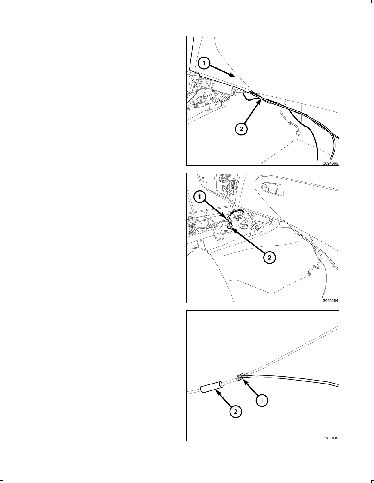
NOTA:Cuandocoloqueelcable,asegúresedeno
dañarlosterminalesdeéste.
47.Introduzcaelmazodecables(2)delacámarademar
chaatrásporelP/Iinferior(1)paraconectarelmazo
decablesdealimentacióndeencendidode12Vyel
TGM.
48.Retirelacintadeaislamiento(1)deloscablesdel
conectordelmazodecablesdealimentaciónde
encendidode12V(2)paraempalmarloscables.
11
49.Prepareelempalme/engarzadodelcablede
alimentacióndelacámarademarchaatrás(PK/OR)
a(DB/PK)delconectordelmazodecablesde
alimentacióndeencendidode12Vdelasiguiente
forma:
a.CorteelcableDB/PKdealimentacióndeencen
didode12V.
b.Pele13mm(0.5in)deaislamientodecadacable
quehayaqueempalmar.
c.Coloqueuntrozodetubotermorretráctiladhesivo
(2)sobreunodelosladosdelcable.Asegúrese
dequeeltubosealosuficientementelargocomo
paracubrirysellarlatotalidaddelazonade
reparación.
d.Coloquelosfilamentosdecablessuperpuestos
enelinteriordelclipdeempalme(1).
Nov16,2010K6861117
Page 56
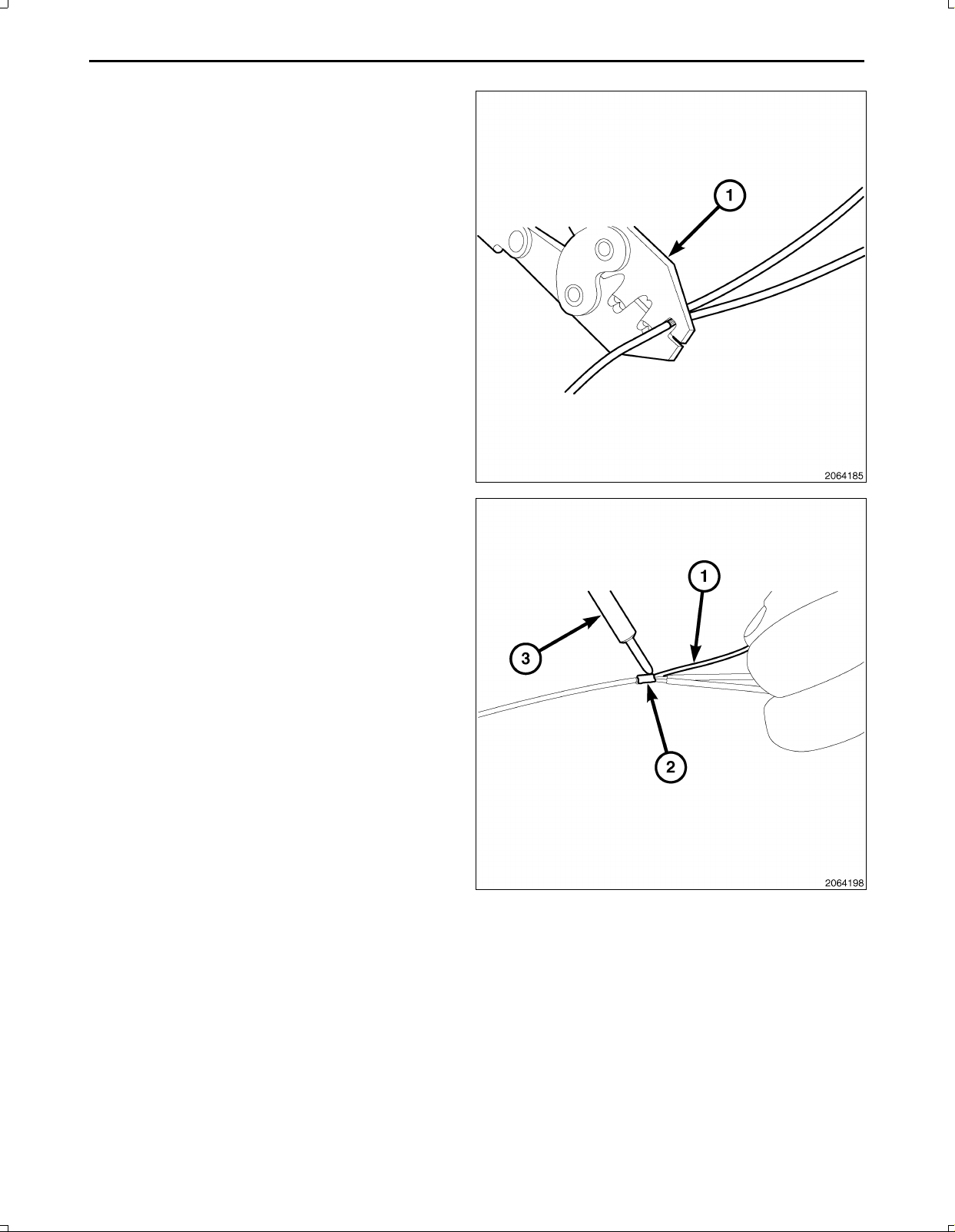
12
50.Utilizandounaherramientadeengarces(1),Mopar®
n/p05019912AAounproductoequivalente,engarce
elcollaríndelempalmeyloscablesconjuntamente.
PRECAUCIÓN:Noutilicesoldaduradeltipodenúcleo
ácido.
51.Conunaherramientadesoldadura(3),sueldela
conexión(2)juntoconnúcleoderesina(1).
Nov16,2010K6861117
Page 57
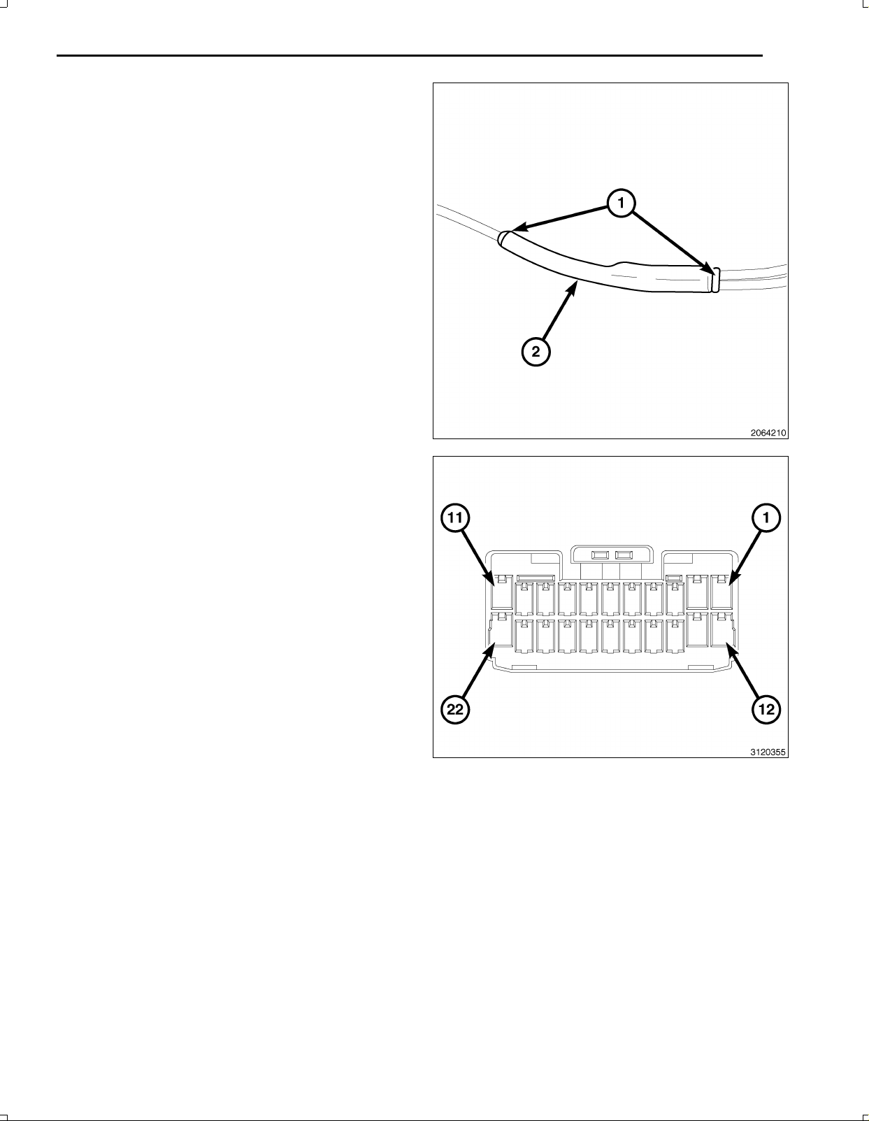
52.Centreeltubodecontraccióntérmica(2)enla
juntadelsoladorycaliénteloconunapistoladeaire
caliente.Calientelauniónhastaqueeltuboquede
firmementeselladoyelsellador(1)salgaporlosdos
extremosdeltubo.
53.Empalme/engarceelcabledemasadelacámarade
marchaatrás(BK)alamasa(BK)delconectordel
mazodecablesdealimentacióndeencendidode12V,
talycomoseindica.
13
NOTA:Esposiblequeyahayaunconectorde22pines
conectadoalTGM.Utiliceeseydescarteelquesepro
porcionaconelkit.
54.Retirelalengüetadebloqueodelconectordelconec
tordelmazodecablesdelTGM3.
55.Introduzcaloscablesdelmazodelacámaraenel
conectordelmazodelTGM3delasiguienteforma:
a.Cabledeseñal(GY/LB)cavidad15
b.Cablederetorno(GY/OR)cavidad16
c.Cabledelprotector(descubierto)cavidad17
Nov16,2010K6861117
Page 58
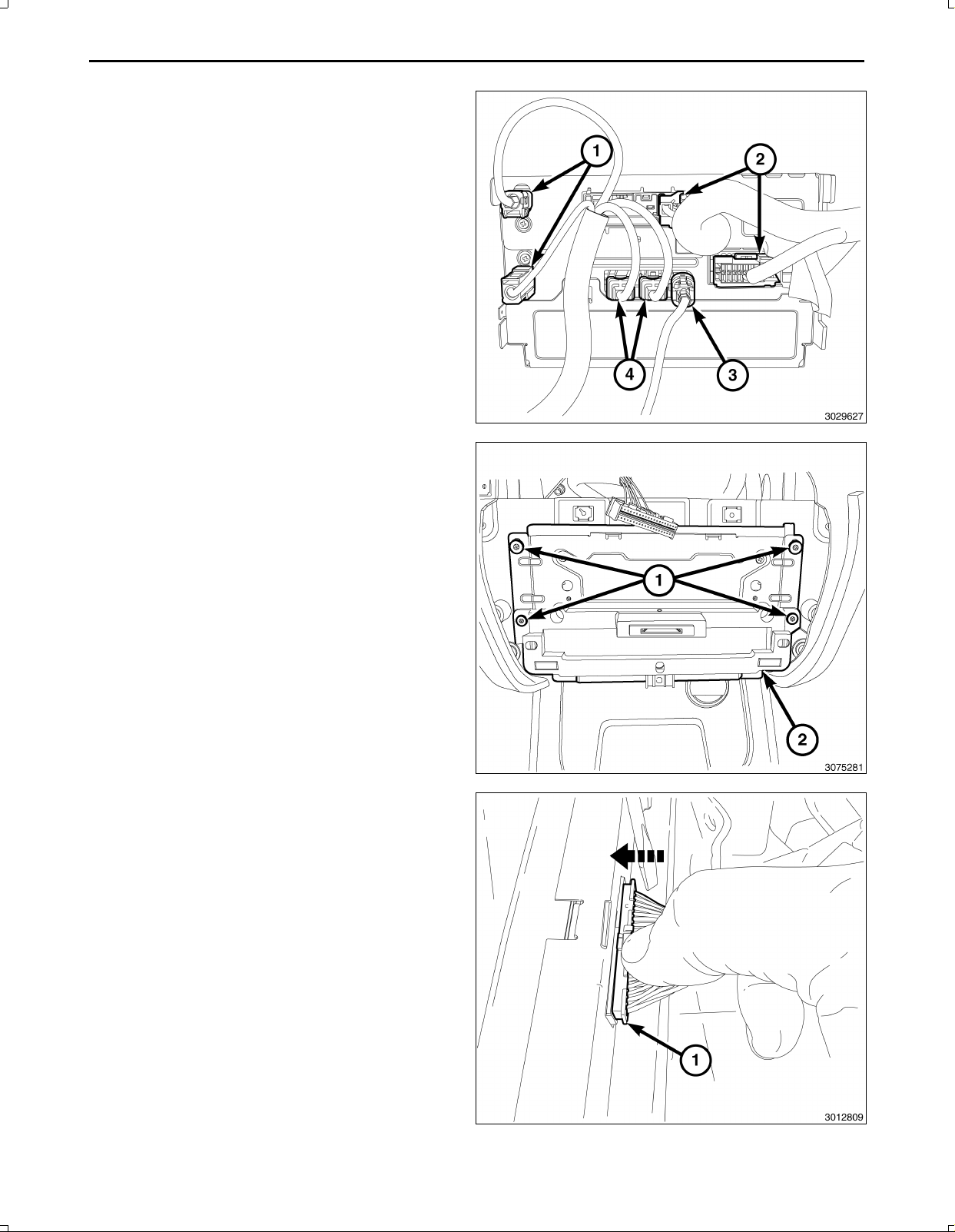
14
56.Conectelaantena(s)(1),loscablesdeRFHUByUCI
(4),elcabledevídeo(3)ylosconectoresdelosca
bles(2)delTGM.
NOTA:Asegúresedequeelconectorde40vías(1)del
grupodeconmutadoresestácolocadoporencimadel
TGMparaaccedercuandoconecteelgrupodecon
mutadores.
57.ColoqueelTGM(2)einstalelostornillosderetención
(1)almódulodepasarelatelemática(TGM)(2).
58.Enchufeelconectorde40vías(1)enelgrupodecon
mutadores.
Nov16,2010K6861117
Page 59
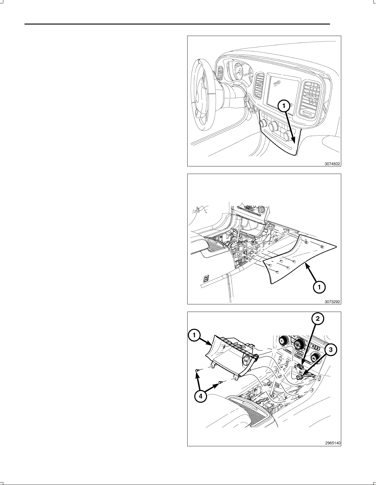
59.Coloqueelgrupodeconmutadores(1)ypresione
firmementeenelpaneldeinstrumentosparafijarlos
retenedores.
60.Coloqueelpanelexteriordelaconsoladesuelo(1)
ypresionefirmementeparafijarlosdosretenedores
quefijanelpanelalpaneldeinstrumentosyloscinco
retenedoresquefijanelpanelexterioralaconsolade
suelo.
15
61.ConecteelmazodecablesdeLED/luz(2)alcompar
timentodealmacenamiento(1).
62.Conecteelmazodecablesdealimentacióndeen
cendidode12V(3)enlaparteposteriordelcomparti
mentodealmacenamiento(1).
63.Coloqueelcompartimentodealmacenamiento(1)y
empujefirmementeparafijarlosdosretenedoresdel
panelexteriordelaconsoladelsuelo.
64.Instalelostornillos(4)quefijanelcompartimentode
almacenamiento(1)alaconsola.
Nov16,2010K6861117
Page 60
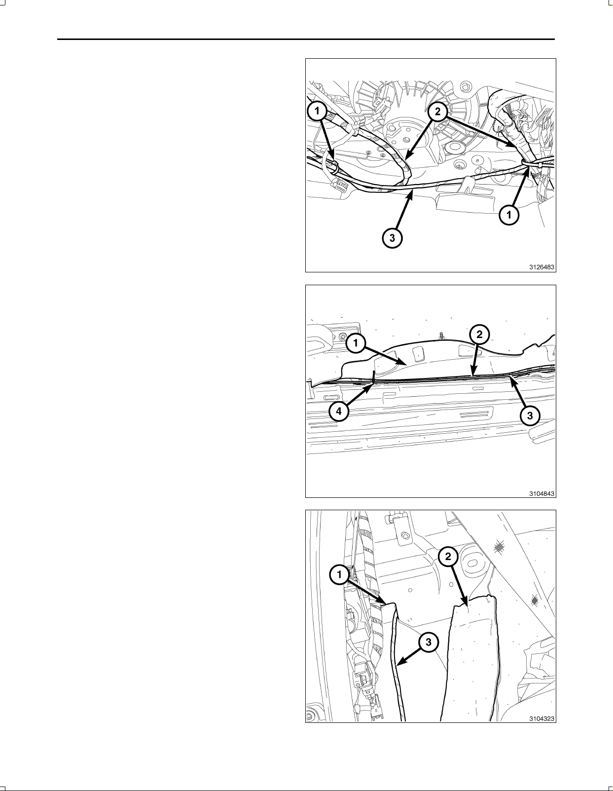
16
65.Dirijaelmazodecablesdelacámarademarchaatrás
(3)bajoelladoderechodelpaneldeinstrumentosy
fijeelmazodelvehículo(2)conbridas(1).
66.Dirijaelmazodecablesdelacámarademarchaatrás
(3)bajoelbordedelatapicería(1)bajotapiceríade
loslimpiabarrosderechosyelrevestimientoinferior
delmontanteB.Coloqueelmazodecablesdelve
hículo(2)conbridas(4)sifueranecesario.
67.Introduzcaelmazodecablesdelacámarademarcha
atrás(3)porlaaperturadelpaneldelacarrocería(1)
traselaislantedelasientotrasero(2)eneláreadel
maletero.
68.Vuelvaacolocarelaislamiento(2).
Nov16,2010K6861117
Page 61
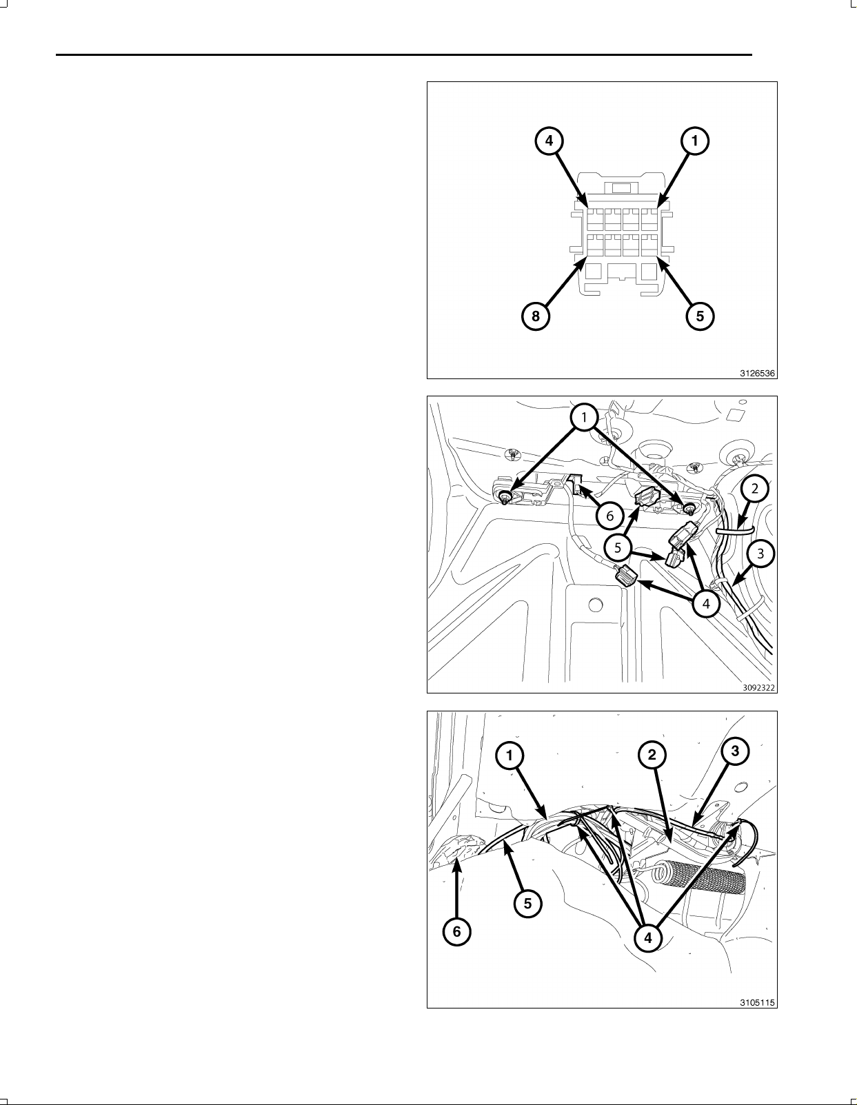
69.Retirelalengüetadebloqueodelterminaldelconec
tordelconectordelacámarademarchaatrás.
70.Introduzcaloscablesdelmazodelacámarademar
chaatrásenelconectordelacámarademarchaatrás
delasiguienteforma:
a.Cabledealimentacióndeencendidode12V(PK/
OR)cavidad2
b.Cablederetornodeseñal(GY/OR)cavidad3
c.Cabledeseñal(GY/LB)cavidad4
d.Cabledelprotector(descubierto)cavidad7
e.Cabledemasa(BK)cavidad8
71.Coloqueelconjuntodelucesconlacámarademar
chaatráseinstalelastuercasdefijación(1).
72.Conectelosconectoresdelmazodecablesdelcon
mutadorylaluz(5,6).
73.Dirijaelmazodecablesdelacámarademarchaatrás
(3)conelmazodelmaleteroyfíjeloconbridas(2)si
fueranecesario.
74.Enchufelosconectoresdelacámarademarchaatrás
(4).
17
75.Dirijaelmazodecablesdelacámarademarcha
atrás(3)porlabisagradelmaletero(2)ycolóquela
conbridas(4)sifueranecesario.
76.Dejeaparteelexcesodelmazodecables(1)yfíjelo
conunabrida(4).
77.Introduzcaelmazodecables(1)porelhuecodela
ruedafijandoeláreademovimientodelmaletero/bis
agraconbridas(4)sifueranecesario.
78.Introduzcaelmaterialaislante(6)porelorificiodeac
cesopordondeelmazodecablesdelacámarade
marchaatrás(5)porelpaneldelacarroceríapara
protegerloderozaduras.
Nov16,2010K6861117
Page 62
18
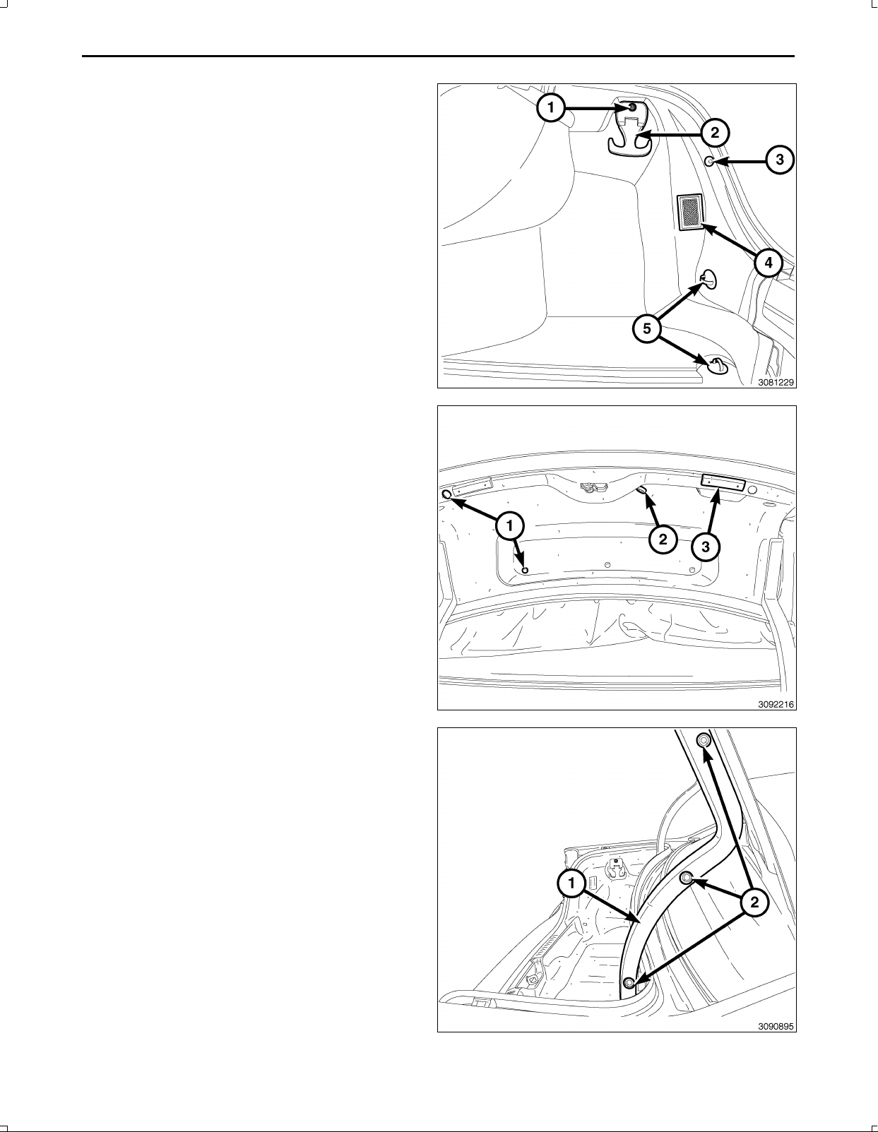
79.Coloqueelrevestimientodelacubiertadelhuecode
laruedadelasiguienteforma:
a.Coloquelacubiertadelhuecodelarueday
enchufeelconectordelmazodecables(4)dela
luzdelmaletero.
b.Montelosganchosinferioresdelareddecarga
(5).
c.Instaleelretenedor(3)quefijaelrevestimientode
latapadelhuecodelarueda.
d.Monteeltornillodelganchodelareddecarga(1)
yelganchodecargasuperior(2).
NOTA:Eltiradordeldesbloqueodelmaleteromanual
(2)sedebedirigirhaciaelrevestimientodelatapadel
maletero.
80.Coloqueelrevestimientodelatapadelmaletero,
instalelosnueveelementosdefijación(1)ylosdos
topesdelparachoques(3)alatapadelmaletero.
81.Coloqueelrevestimientodelabisagraderecha(1)e
instalelosdispositivosdefijación(2).
Nov16,2010K6861117
Page 63
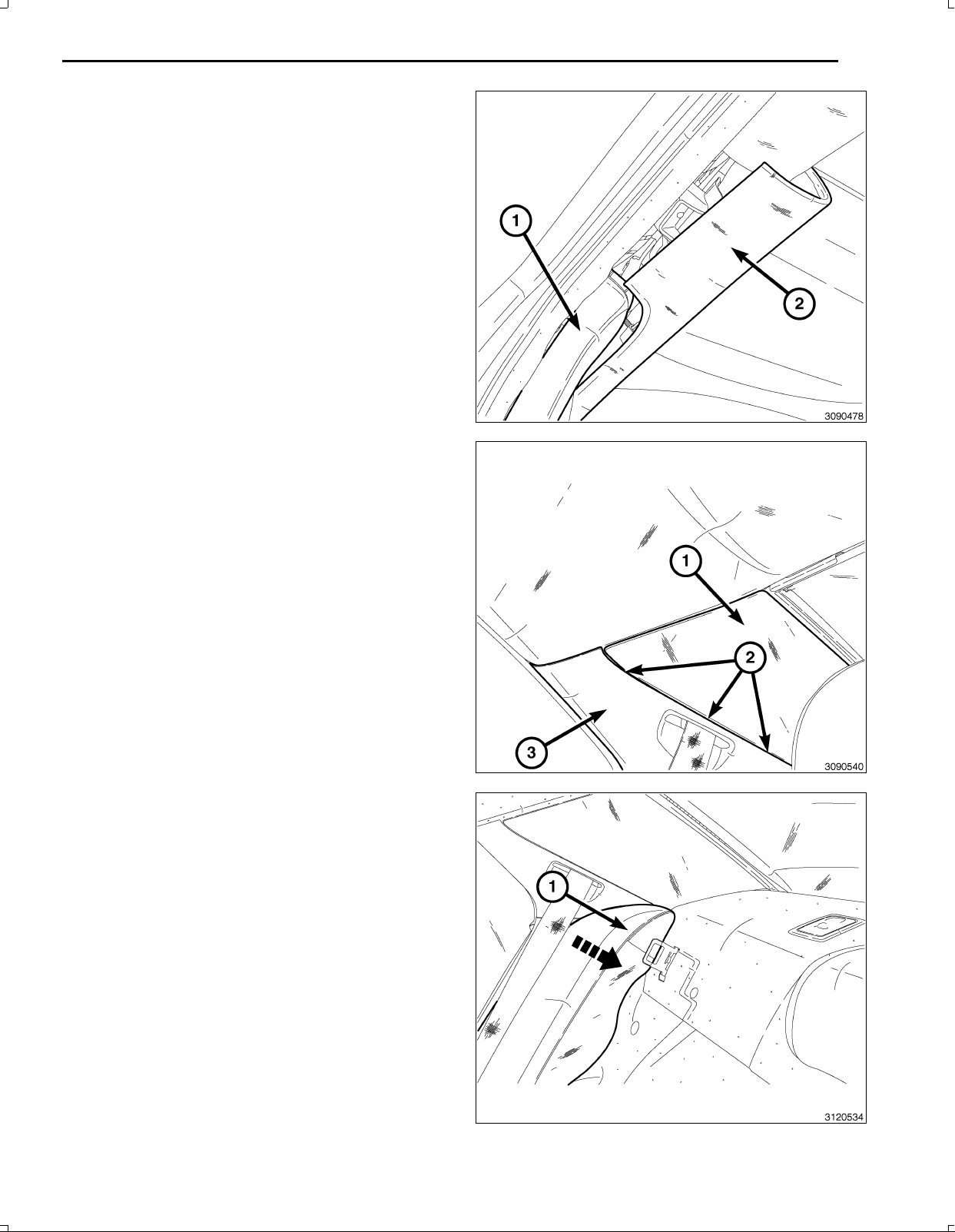
82.EnelcasodeDodgeúnicamente,coloqueelreves
timientodelmontanteC(1)concuidadoyfíjeloen
sulugarconlosretenedores,y,acontinuaciónfijeel
revestimiento(2)conlosretenedores.
83.EnelcasodeChryslerúnicamente,retirelos
treselementosdefijacióndelapartesuperiordel
revestimientodelmontanteC(1)einstálelosenla
carrocería(2).Desliceelrevestimientodelmontante
C(1,3)paraengancharlostresretenedores(2)yfije
laparteinferiordelrevestimientodelmontanteC(3)
conloselementosdefijación.
19
84.Coloqueelpernodelrespaldodelasientotrasero(1)
ypresioneparafijarelclipsuperiorenlacarrocería.
Nov16,2010K6861117
Page 64
20
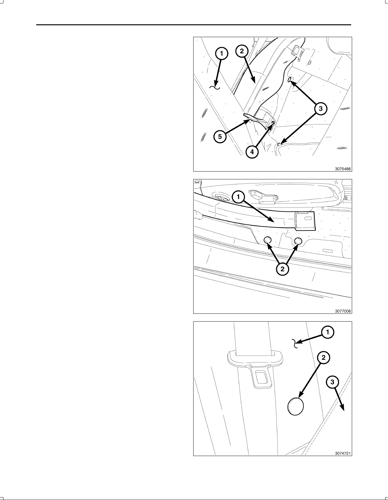
85.Coloquelapartedelanteradelrevestimientolateral
delmaleteroeinstalelosretenedores(3)quelofijan.
86.Instaleelpernodefijacióndelrefuerzodelrespaldo
delasientotraseroderecho(4).
87.Vuelvaacolocarlalengüetadelatapicería(5),que
cubreeltornillodemontajedelsoportedelrefuerzo
delrespaldodelasientotrasero(4).
88.Instaletodoslosdispositivosdefijacióndepresiónde
latapicería(2)deloslimpiabarrosdelanteroytrasero
ydelazonadelzócaloinferiorderecho.
89.ColoqueelrevestimientoinferiordelmontanteBdere
cho(1)fijandolosclipsderetenciónenlaparteinferior
delrevestimiento.
90.Siestáequipado,instalelacubiertayeltornillodefi
jacióndelpanelderevestimientoinferiordelmontante
Bderecho(2).
Nov16,2010K6861117
Page 65
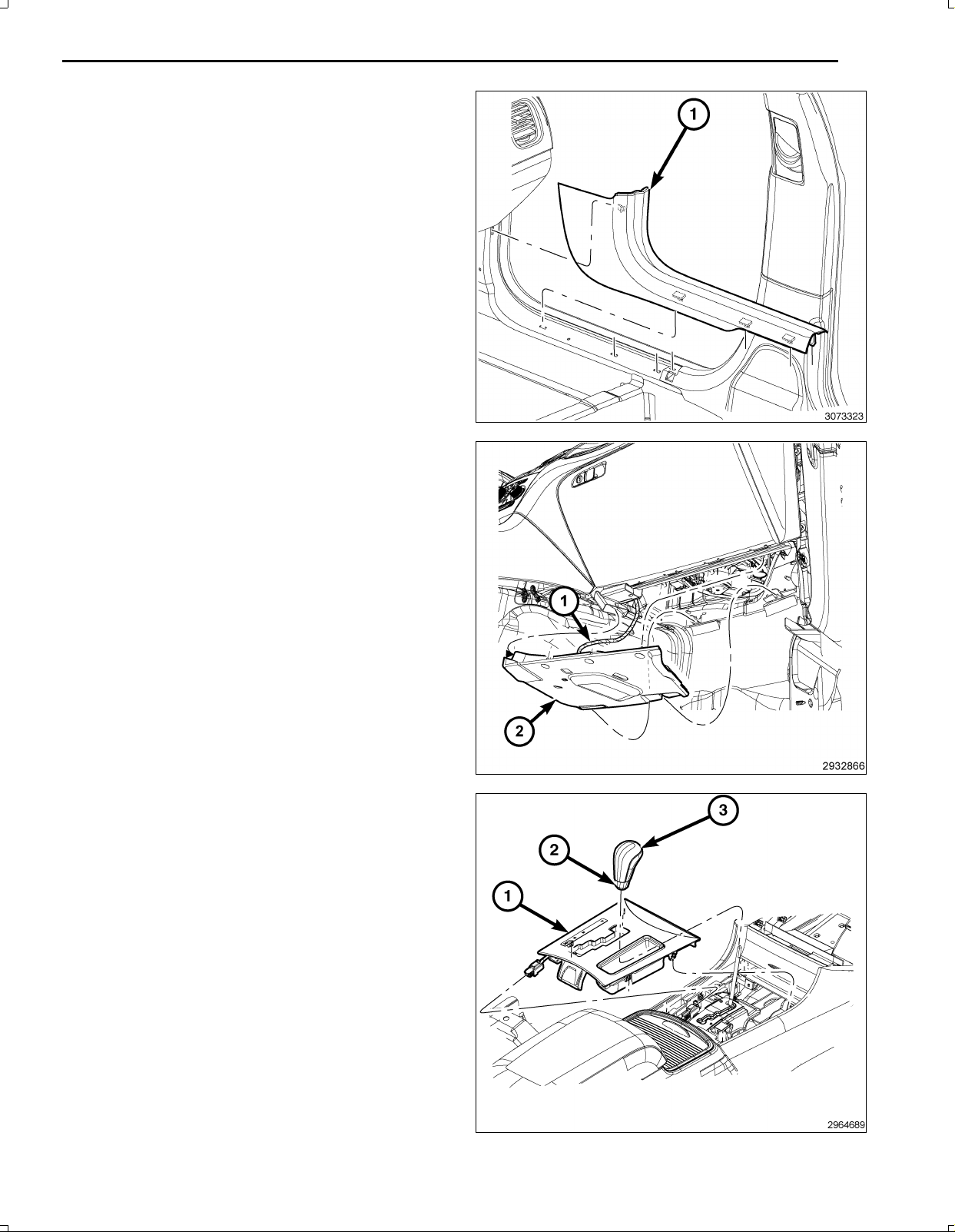
91.Instaleloslimpiabarrosdelaspuertasdelantera(1)y
traseraderechascolocandoyfijandolosretenedores.
92.ConecteelmazodecablesdeLED(1)alaluzde
suelodelsilenciadordelpaneldeinstrumentos(2).
93.Coloqueelsilenciadordelpaneldeinstrumentosdel
ladoderechoyfijeloselementosdefijación.
21
94.Enchufeelconectordelmazodecablesdelembelle
cedordelapalancadecambios.
95.Presioneconfirmezaelembellecedordelapalanca
decambios(1)enlaconsoladesueloparafijarlos
retenedores.
96.Desliceelanillodefijaciónporelejedelcambio(2)
ydesliceelpomodelcambio(3)enelejeypresione
hastaencajarloensusitio.
97.Conecteelcablenegativodelabatería.
98.Instalelacubiertadeneumáticoderepuesto/alfombra
delsuelodelmaleteroqueestáencimadelhuecodel
neumáticoderepuesto.
Nov16,2010K6861117
Page 66

22
CONFIGURACIÓNDELACÁMARATRASERADELVEHÍCULO
Debeactualizarelnúmerodeidentificacióndelvehículo(VIN)conelcódigodeventasdelaccesorioañadidopara
poderactivarelsistema.ConlapáginawebdeDealerCONNECTylaherramientadediagnosis,realiceelsiguiente
procedimiento:
1.Iniciesesiónenhttps://dealerconnect.chrysler.com
2.Enlapantalla“VehicleOption”(Opcióndelvehículo)queseencuentraenlacategoría“GlobalClaimsSystem”
(Sistemadepedidosglobal)delaficha“Service”(Servicio),introduzcaelVINdelvehículoyelcódigodeventasXAC
(ParkViewRearBackUpCamera)(XAC[Cámaratrasera])en“DealerInstalledOption”(Componenteopcional
instaladooriginal).
3.AsegúresedequeelnuevocódigodeventassehayaañadidoalVINcorrectamente.
ConlaherramientadediagnosisconectadaaInternet(porpuertoEthernetoconexióninalámbrica)yalvehículo,realice
elsiguienteprocedimiento:
4.Conlaherramientadediagnosis,seleccionePREPARACIÓNDELVEHÍCULOy,acontinuación,seleccione
RESTABLECERCONFIGURACIÓNDELVEHÍCULO.
5.Sigapasoapasolasinstruccionesdelaherramientadediagnosisparacompletarlaconfiguracióndelvehículocon
cámarademarchaatrásconvisualizacióntraseraparaestacionamiento.
Nov16,2010K6861117
 Loading...