

Page 1
DVD REAR SEAT VIDEO SYSTEM
CHRYSLER PACIFICA
INSTALLATION INSTRUCTIONS
Read entire instructions thoroughly before starting.
TOOLS REQUIRED:
• Non-metal trim stick • Phillips screwdriver • T20 Screwdriver • Scissors • Sharp utility knife
• New roll of masking tape • Metal fish wire • 8mm Deep well socket • Socket wrench with long
extension • Foam Tape
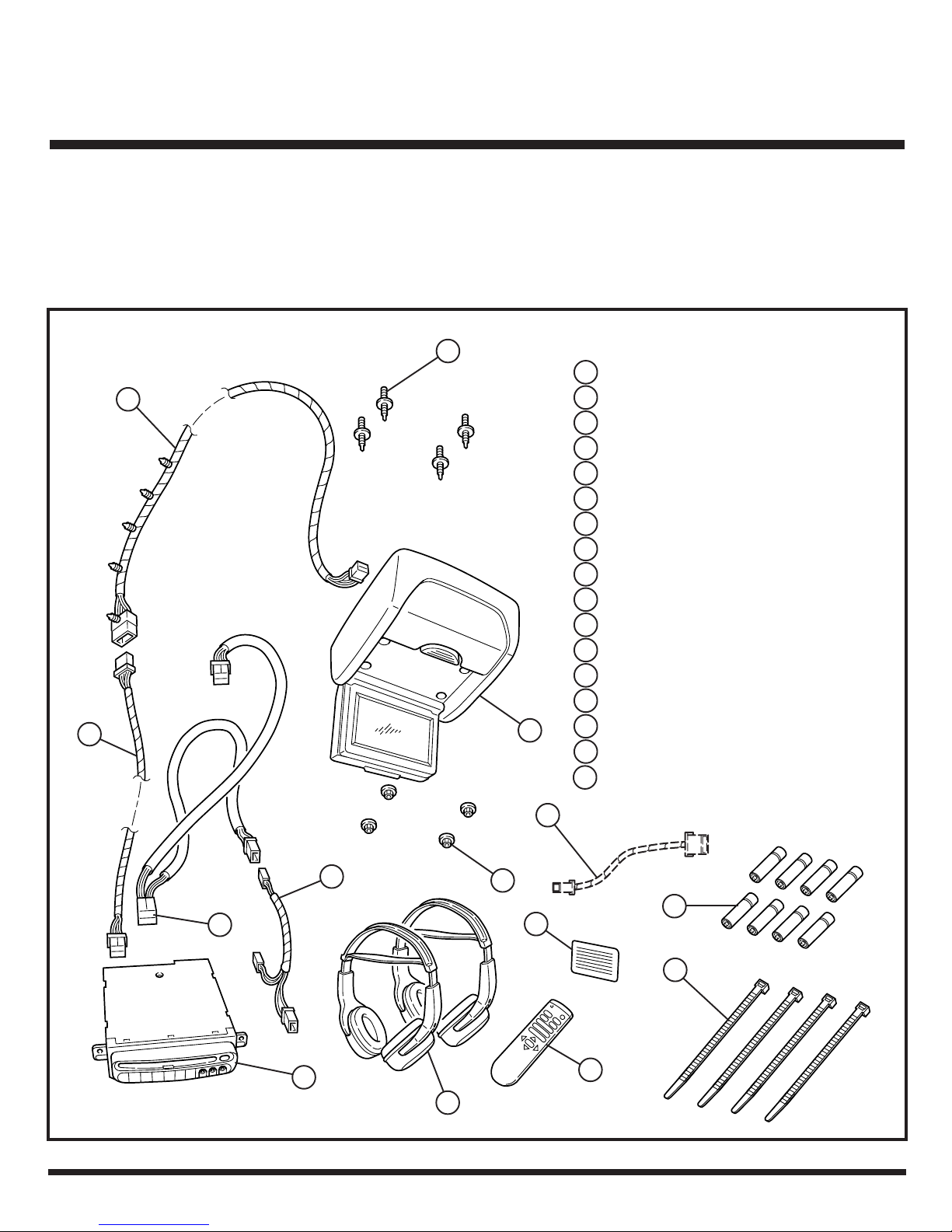
CONTENTS:
2
7
Item Qty. Description
4
1 1 Headliner Template
2 1 Overhead Harness
3 4 Tie Straps
4 4 Stud Collar Fasteners
5 1 Screen Console
6 4 Hex Nuts
7 1 Extension Harness
8 1 DVD Player
9 1 Power Harness
10 1 Jumper Harness
11 8 Batteries
12 2 Headphones
13 1 DVD Remote
14 1 Operating Instructions
5
15 1 Mercury Warning Label
16 1 Installation Instructions
17 1 REV/RDV Jumper Harness
#04869090AC (order separately)
17
10
9
8
12
6
11
15
3
13
K6858779 03/14/2006 Page 1 of 6
Page 2
Right I/P
Center Bezel
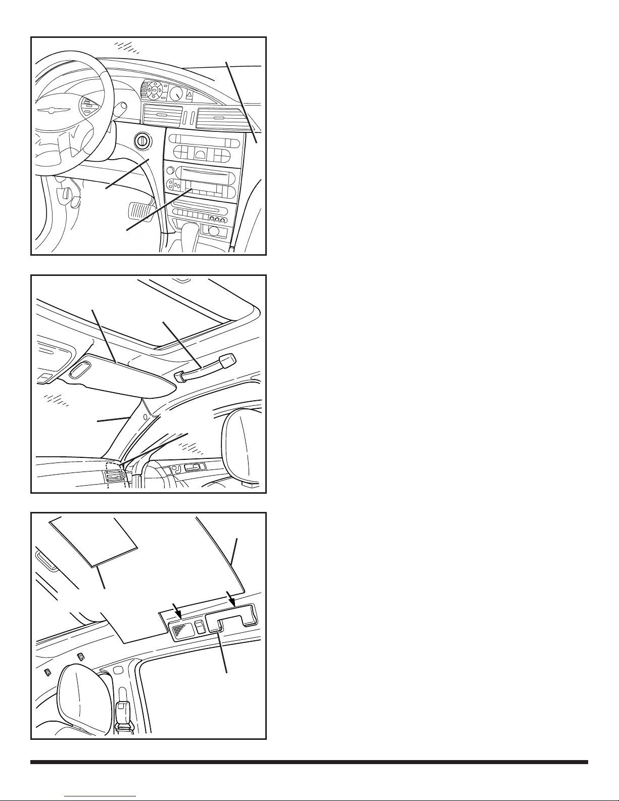
1) Disconnect and isolate negative battery cable.
A – Interior Trim Panel and Component
Removal:
2) Detach the center console shift bezel.
3) Remove ignition key bezel.
4) Remove left and right I/P center bezels using a non-
metal trim stick.
Sunvisor
and Clip
A-Pillar Trim
Left I/P
Center
Bezel
Radio
Grab Handle
5) Disconnect and remove the CD/DVD player or
cubby bin (four phillips screws).
6) Disconnect and remove the radio (four phillips
screws).
7) Remove right (passenger’s side) A-pillar trim panel
(one phillips screw).
8) Remove right side I/P access panel.
9) Disconnect and remove right sunvisor (two T20
screws).
10) Remove right sunvisor clip (one T20 screw).
I/P Access
Panel
Headliner
Template
11) Remove right front headliner grab handle (two phillips
screws).
B – Trim Out the Headliner:
1) Trim out supplied template (Item 1) along the dotted
Headliner Trim-Out
Indicator
Right Grab
Handle
Assembly
K6858779 03/14/2006 Page 2 of 6
lines.
2) Position template to the headliner, making sure that
it aligns to the left and right grab handle
assemblies.
3) Secure template to headliner where indicated using
new masking tape.
Page 3
Headliner
4) Trim out the headliner per template instructions using
a sharp utility knife.
C – Install Overhead Harness:
Overhead
Harness
White
Connector
Black
Connector
Right A-Pillar
Screen Console
Opening
Overhead
Harness
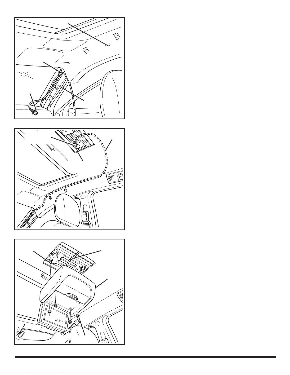
1) Position overhead harness (Item 2) to the right A-
pillar as shown. Secure it to the existing harness
using two tie straps (Item 3).
2) Carefully pull headliner down just enough to allow
the overhead harness to route rearward.
CAUTION! Headliner is held in place with velcro
strips. Take care that headliner does not crease.
3) Route harness in-between the headliner and inner
roof panel, keeping clear of the sunvisor and grab
handle openings.
CAUTION! Stay clear of airbag tether in the A-pillar
and side curtain airbag in the headliner.
Stud Collar
Fasteners (4)
Overhead
Harness
Screen
Console
4) Continue to route harness rearward then across to
the screen console opening as shown.
NOTE: the use of a metal fish wire may be needed.
5) Re-install sunvisor, clip, and grab handle.
D – Install Screen Console:
1) Using a #4 inverted torx driver, install four supplied
stud collar fasteners (Item 4) to the inner roof
crossmember.
2) Plug and lock overhead harness connector into the
screen console (Item 5).
Nuts (4)
K6858779 03/14/2006 Page 3 of 6
Page 4

Extension
Harness
Overhead
Harness
3) Install screen console with four supplied nuts
(Item 6) using an 8mm deep well socket.
E – Install Extension Harness:
1) Hand feed black connector on extension harness
(Item 7) down inside the I/P, keeping between the
A-pillar and I/P top cover.
NOTE: Keep harness away from any sharp edges,
heat sources, or moving parts.
2) Plug white connector on extension harness into the
overhead harness. Wrap this connection with foam
tape to prevent rattles.
Radio
Opening
Radio
Glove Box
Opening
Extension
Harness
Existing
Power
Harness
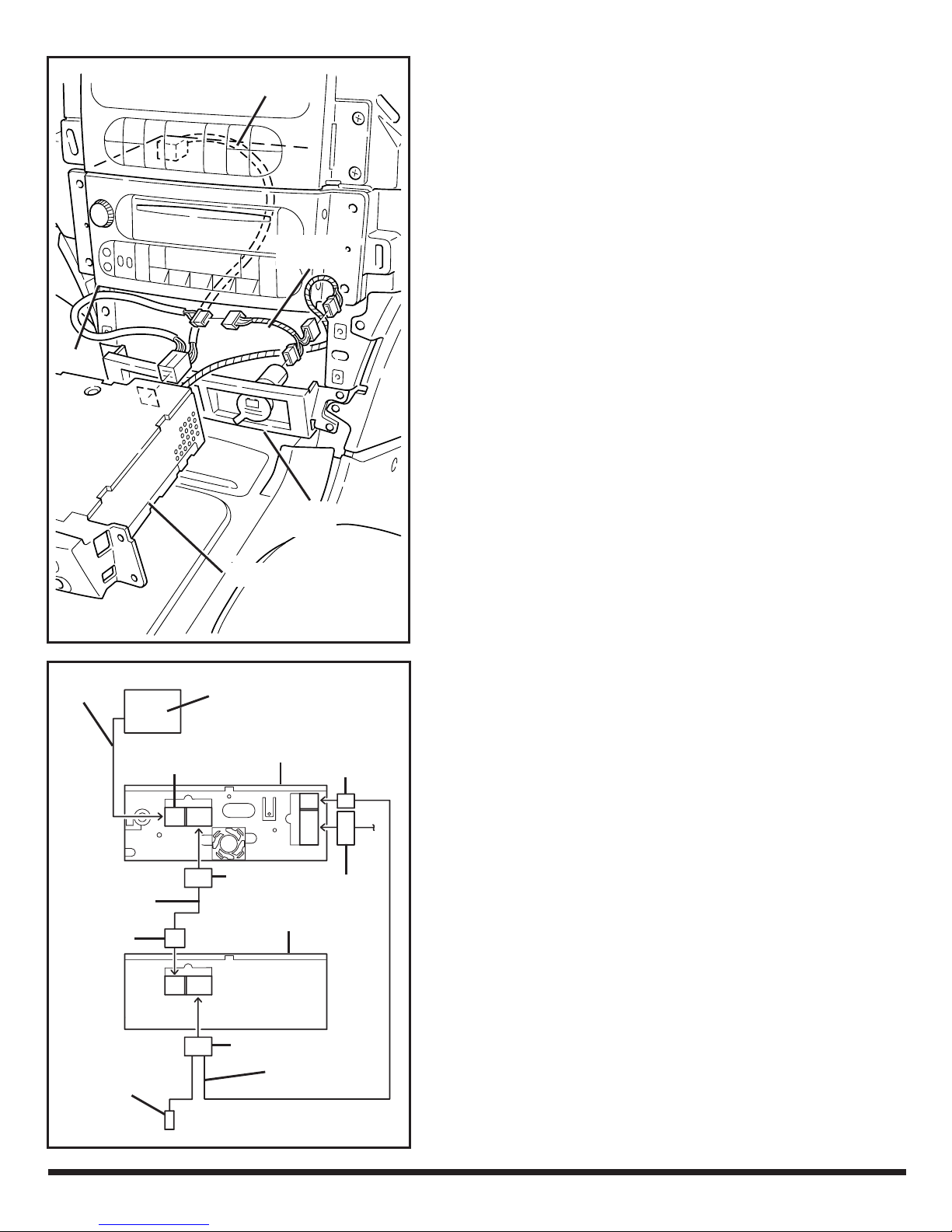
3) Route harness across the back of glove box
opening and into the radio opening.
4) Secure harness to existing vehicle harness at the
back of glove box using two tie straps.
NOTE: Installation of existing DVD—proceed to F1.
Installation of new DVD—proceed to F2.
Installation of new DVD/CD player with DVD/CD
radio—proceed to F3
F1 – Install DVD Player:
1) Plug 12-way extension harness connector into the
existing DVD player.
2) Plug 16-way power harness connector into the
existing DVD player.
3) Install DVD player using four previously removed
phillips screws.
4) Plug 10-way power harness connector into the
radio.
5) Re-connect and re-install the radio.
DVD or
CD/DVD Player
K6858779 03/14/2006 Page 4 of 6
6) Proceed to Section G for operation test.
Page 5
Radio
Power
Harness
Jumper
Harness
Power
Outlet
DVD Player
NOTE: Some vehicles may be equipped with an existing power harness. The supplied power harness (Item
9) and jumper harness (Item 10) will not be needed.
F2 – Install New DVD Player:
1) Plug 12-way extension harness connector into the
existing DVD player (Item 8).
2) Plug in existing 10-way behind radio or use (Item 9).
3) Re-connect and re-install the radio.
4) Plug in existing 16-way behind DVD player or use
(Item 9).
NOTE: If using existing power harness—skip to Step 7.
5) Plug 2-way power harness connector into supplied
jumper harness (Item 10).
6) Disconnect right (passenger’s side) power outlet.
Plug 2-way jumper harness connectors in-between.
7) Install DVD player using four previously removed
phillips screws.
Overhead
Harness
#04869090AC
Jumper
12 Way
2 Way
Jumper
12 Way
VES Screen
DVD/CD
Radio
16 Way
DVD/CD
Player
16 Way
Power
Harness
10 Way
22 way
F3 – Install New DVD/CD Player With DVD/
CD Radio:
1) Plug 12-way extension harness connector into the
DVD/CD Radio.
2) Plug in existing 10-way behind DVD/CD Radio or
use (Item 9).
3) Plug in 16-way (Item 9) behind DVD/CD Player.
4) Plug in existing 22-way behind DVD/CD Radio.
5) Plug in 16-way (Item 17, 04869090AC) behind DVD/
CD Radio.
6) Plug in 12-way (Item 17, 04869090AC, order
separately) behind DVD/CD Player.
7) connect and install the DVD/CD Radio and Player.
8) Proceed to Section G for operation test.
K6858779 03/14/2006 Page 5 of 6
Page 6
G– Operation Test:
1) Re-connect the vehicle’s battery.
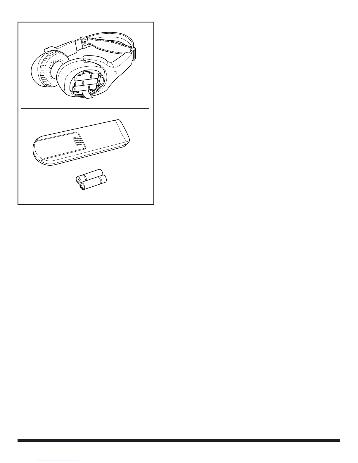
2) Place supplied batteries (Item 11) into both
headphones (Item 12) and DVD remote (Item 13).
3) Slowly remove plastic cover from the display screen.
4) Turn on ignition, unit will power up. Insert a known
good DVD.
5) Verify function of headphones and DVD remote
using supplied Operating Instructions (Item 14).
6) Place Operating Instructions in the vehicle’s glove
box.
7) Refer to vehicle Owner’s Manual for headphone
and video instructions.
NOTE:
15)
Peel and stick mercury warning label (Item
to lower portion of forward facing surface on the
left (driver’s side) B-pillar.
K6858779 03/14/2006 Page 6 of 6
 Loading...