

Page 1
1
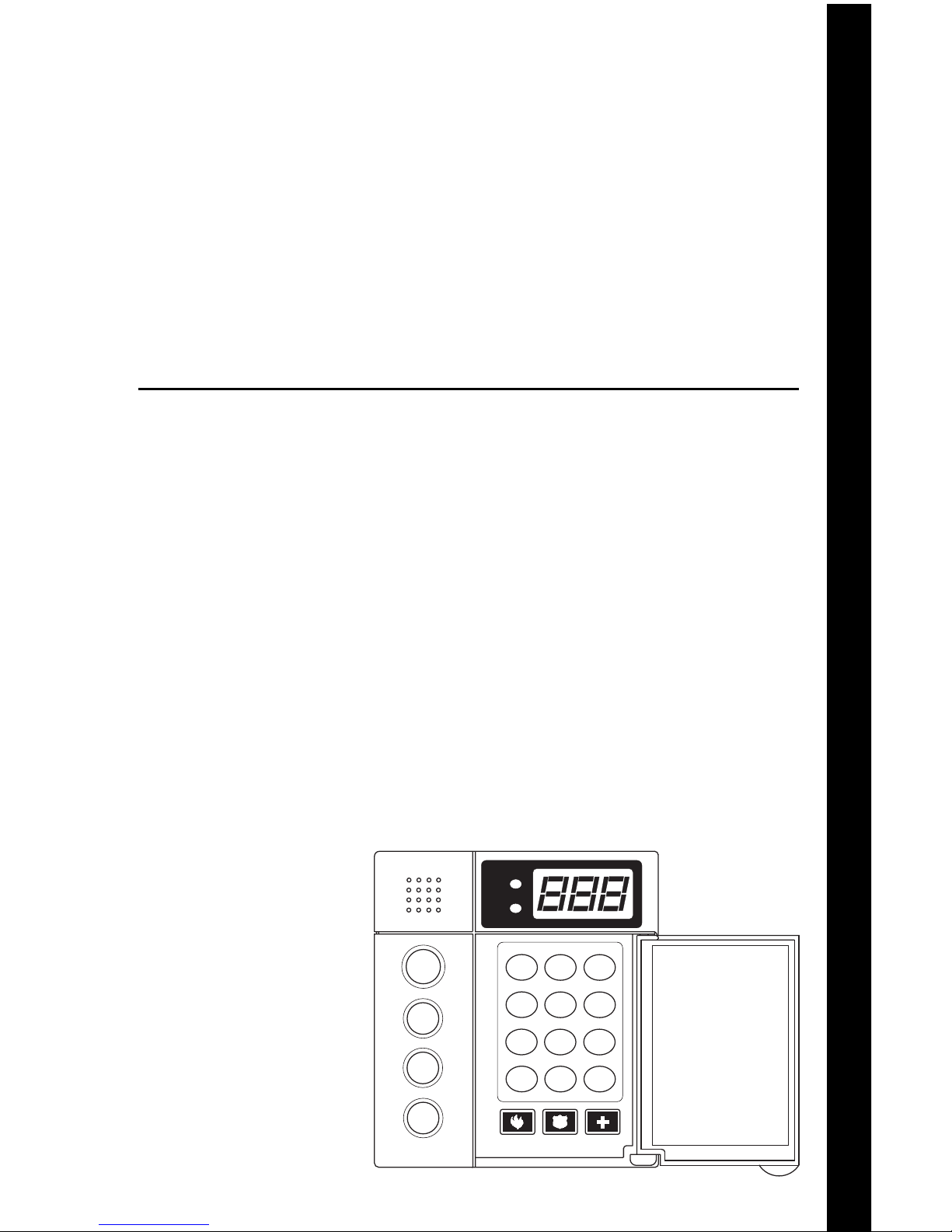
How to Use Your
Moose Security System
ZXSSD
Control Station
1
23
4
56
7
89
CLEAR
0
ENTER
NIGHT
STAY
AWAY
VIEW INFO ALM MEM
EVENT LOG
BYPASS DELAY ARM CHIME
RST SMOKE TEST PROGRAM
QUIT ACCESS INSTANT
HOME NEXT
READY
TROUBLE
D
OFF
CANCEL
Page 2

2
INTRODUCTION
Thank you for choosing the ZX200/ZX210 or the ZX400/ZX410 Security Control.
This control will provide you with years of reliable operation when properly installed
and maintained.
To maximize the benefits of your Security System, it is important to carefully read
the entire contents of this manual and become familiar with all control operations.
Your Security Company Representative has recorded confidential information about
your system in this manual, therefore, you should store it in a secure place. Contact
your Security Company Representative immediately with any questions.
It is important to note however, that no security system provides total protection
over life or property, nor can it detect intrusion or other conditions in all circumstances. Ask your Security Company Representative to fully review the features of
your system, indicate areas of potential risk, and detail recommendations for future
upgrades to the system.
The following is a list of general precautions you should follow to maximize the
benefits of your security system:
1. The system must be tested at least once per week to ensure proper operation.
Contact your Security Company Representative for testing procedures and
scheduling of a regular maintenance program.
2. If the system is malfunctioning, have it serviced by a qualified professional as
soon as possible.
3. If the electrical system of the building is altered, be sure that the changes do
not create an interruptible power supply to the control panel.
4. If the telephone system is serviced, test the security system to ensure that
communication to the Central Station is intact.
5. Motion detectors are designed to detect specific types of motion within a
defined area. Be sure that you understand which areas are protected and under
what conditions the system is active (temperature and time variations, etc.).
6. Smoke detection devices cannot detect all types of fire under all circumstances.
Have your Security Company Representative explain the limitations of your fire
system. Have smoke detectors cleaned and tested on a regular basis.
7. Security systems rely upon electrical power as a primary power source. When
the electrical power fails, the control is powered by a standby battery. The
standby battery is automatically checked by the system and should be replaced
by a qualified service technician at regular intervals.
8. If upon returning to the building, you discover that an alarm has occurred, DO
NOT ENTER THE PREMISES. Immediately contact the proper authorities.
9. Be sure to inform your neighbors that a security system has been installed.
Also explain the meanings of the various audible signals and ask them to
contact the appropriate authorities upon activation of an alarm.
10. The ZX200/ZX210 and the ZX400/ZX410 Security Controls are UL Listed for
Grade A Household Burglary and UL requires that audible burglar alarms be
sounded by a bell and fire alarms by a horn. For combination burglar and fire
alarm systems, the sounder will emit a temporal tone for fire alarms and a steady
tone for burglar alarms. The fire alarm signal takes priority over the burglar bell.
11. UL requires that exit times not exceed 60 seconds. Entrance times may not
exceed 45 seconds. Cutoff time for siren/bell cannot be less than 4 minutes for
residential fire and burglary and 15 minutes for commercial burglary.
Page 3

3
Table of Contents
Operating Your System ............................................................... 5
The SSD Control Station............................................................... 5
The Control Station Keys .............................................................. 6
The Control Station Display .......................................................... 8
Turning Your System ON .............................................................. 9
Turning Your System OFF ........................................................... 10
Silencing Alarms ......................................................................... 10
System Not Ready ......................................................................11
Changing The Security Level ...................................................... 11
Chime ........................................................................................ 12
Printing The Event Log ............................................................... 12
Optional Features ...................................................................... 13
Bypass ........................................................................................ 13
Group Bypass ............................................................................. 13
Selective Bypass/Unbypass ......................................................... 14
Removing Bypass........................................................................15
Force-Arming ............................................................................. 16
Turning Your System ON Using Two Button/Double Press ......... 17
Exit-ON ...................................................................................... 17
Automatic-ON ............................................................................17
Delay Automatic-ON ..................................................................18
Keyswitch Operation .................................................................. 18
Access Output ............................................................................19
Duress ........................................................................................ 19
Panic Keys .................................................................................. 20
User On Premise .........................................................................20
Secondary Function Keys ............................................................ 21
Alarm Conditions ...................................................................... 22
Alarm Memory ........................................................................... 22
Trouble Conditions.................................................................... 23
Silencing Trouble........................................................................23
Identifying Zone Conditions ....................................................... 23
Testing Your System .................................................................. 24
Walk Test ...................................................................................24
Battery Test ............................................................................... 25
Bell Test ..................................................................................... 26
Communicator Test ...................................................................27
Keypad Test............................................................................... 28
RF Signal Strength ..................................................................... 29
TABLE OF CONTENTS
Page 4

4
ZX200/ZX210 Programming .................................................... 30
Remote Connect ........................................................................ 30
Programming the User Passcodes ............................................... 30
ZX400/ZX410 Programming .................................................... 32
Remote Connect ........................................................................ 32
Set Clock ....................................................................................33
Programming the Automatic-ON Feature................................... 34
Programming the Latch Key Feature .......................................... 38
Programming the User Passcodes ............................................... 43
Cancelling the Automatic-ON for Today.....................................45
Cancelling Exit-ON for Today .....................................................46
Multi-Area Operation ................................................................ 47
Fire Detection ............................................................................ 48
Introduction ...............................................................................48
When an Alarm Occurs...............................................................48
Resetting Smoke Detectors ......................................................... 48
Developing An Evacuation Plan .................................................. 49
Fire Prevention And Escape ........................................................ 50
Know Fire Hazards ...................................................................... 50
In Case Of Fire............................................................................ 50
Be Prepared ................................................................................51
Fire Supervisory & Fire Trouble ................................................... 51
SSD Control Station Displays & Descriptions........................... 52
Error Code Display ..................................................................... 53
Glossary ..................................................................................... 54
Index .......................................................................................... 56
System Reference Guide ........................................................... 58
Protection Zones ....................................................................... 60
Owner’s Insurance Premium Credit Requested ....................... 61
FCC Compliance ........................................................................ 63
TABLE OF CONTENTS
Page 5
5
Operating Your System
Read these instructions carefully to familiarize yourself with the
system. Your system has been customized to meet your specific
requirements. Some features discussed are optional and may not be
programmed in your particular system. If you have questions concerning the features on your system, consult your Security Company
Representative.
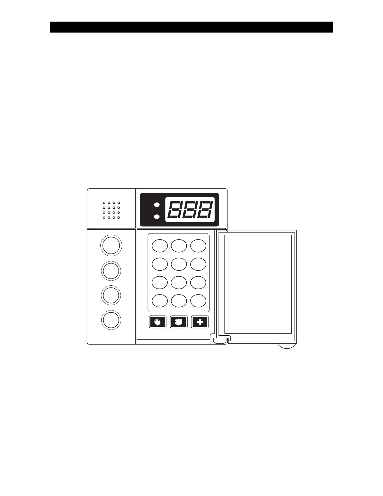
The SSD Control Station
1
23
4
56
7
89
CLEAR
0
ENTER
NIGHT
STAY
AWAY
VIEW INFO ALM MEM
EVENT LOG
BYPASS DELAY ARM CHIME
RST SMOKE TEST PROGRAM
QUIT ACCESS INSTANT
HOME NEXT
READY
TROUBLE
D
OFF
CANCEL
OPERATING YOUR SYSTEM
Page 6

6
OPERATING YOUR SYSTEM
VIEW INFO KEY
This key is used to view system information.
ALARM MEMORY KEY
Allows you to display the most recent zones where an
alarm occurred.
EVENT LOG KEY (ZX400/ZX410 only)
If a printer is attached, you may print the recorded activities.
BYPASS KEY
Allows you to turn your system ON with one or more
zones intentionally left unprotected until the system is
turned OFF.
DELAY ARM KEY (ZX400/ZX410 only)
Extends or postpones the Automatic-ON by one hour.
CHIME KEY
Turns the door/window monitor ON or OFF.
RESET SMOKE KEY
Resets all smoke detectors in alarm.
TEST KEY
Allows you to perform system testing.
PROGRAM KEY
Used to enter the programming mode.
ACCESS KEY
Used to activate a door strike or other access output
function.
QUIT KEY
Used to reset any entry error and to allow you to exit out
of an operation.
INSTANT KEY
Used in programming to store entered data. May also be
used to disable the entry and exit countdown time when
pressed during the countdown time when turning the
system ON with STAY or NIGHT.
OFF CANCEL KEY
Used to turn OFF, silence, or cancel conditions.
The Control Station Keys
1
2
3
4
5
6
7
8
9
0
CLEAR
ENTER
OFF
CANCEL
Page 7
7
OPERATING YOUR SYSTEM
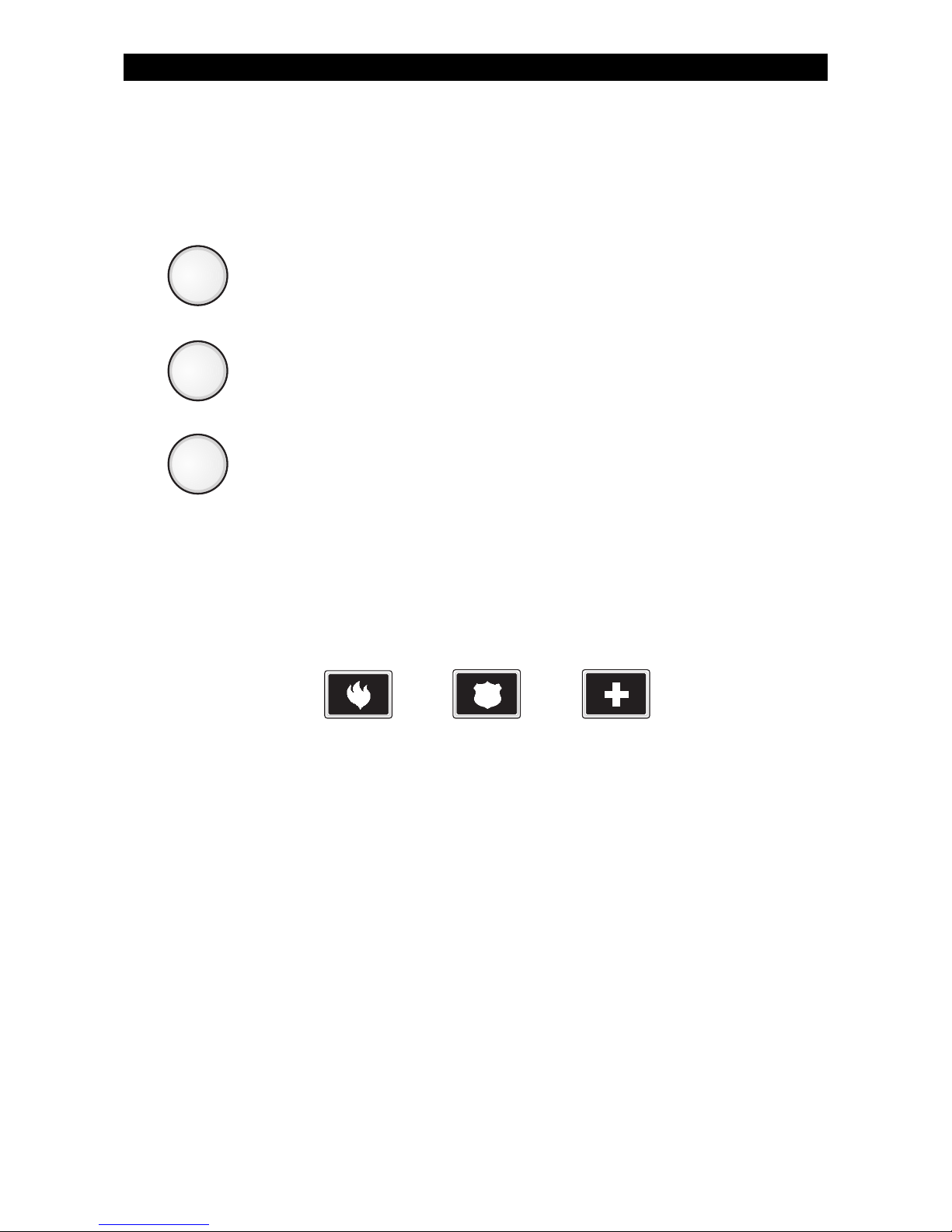
ARMED STATUS INDICATOR
These keys, followed by your passcode, are used to turn your
system ON. Each key corresponds to a different level of
security.
No one at home; total protection; all sensors are ON.
Building is occupied; selected door and window sensors are
ON.
Bedtime; selected door, window and interior sensors are ON.
PANIC KEYS
When enabled, these keys activate the auxiliary alarms (Fire,
Police, Medical). Consult with your Security Company Representative for details.
AWAY
STAY
NIGHT
Fire Police
(Hold Up)
Medical
(Auxiliary)
Page 8
8
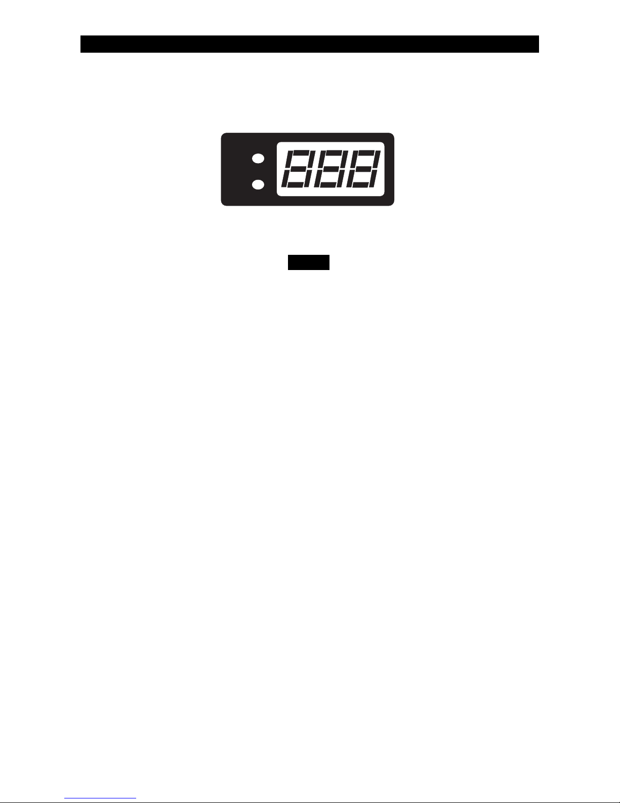
The Control Station Display
The display will turn OFF after four (4) minutes of no
Control Station keypresses or sounder activity. Press
any key to turn the display back ON.
Ready Light Illuminates when the system is ready to be
turned ON. If not illuminated, one or more
zones have not been secured. See Operating Your System - System Not Ready.
Trouble Light Illuminates when system troubles (AC
power failure, low battery, or communication failure), zone troubles, and Burglar
Tamper conditions have occurred. (Burglar
Tamper is not available with the ZX200/
ZX210).
Seven Segment Display The three Seven Segment Display (SSD)
characters display system status, zone
status, and user information. See SSD
Control Station Displays & Descriptions.
READY
TROUBLE
OPERATING YOUR SYSTEM
NOTE
Page 9
9
Turning Your System ON
1. Close all doors and windows.
2. Check for a Ready display and/or light on the Control Station. If
you do not see it, see Operating Your System - System Not Ready.
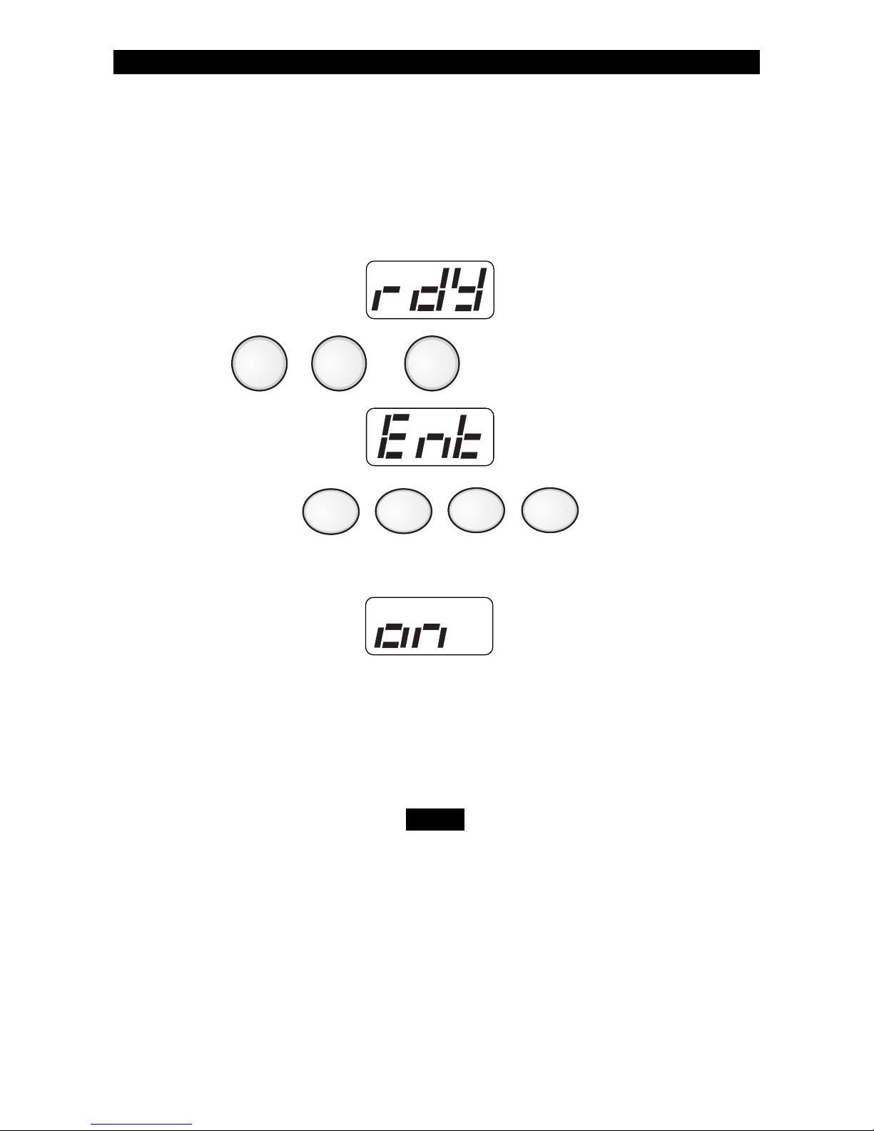
3. Press , or . The Control Station will display:
4. Enter passcode: .
The Control Station will briefly display:
5. The Control Station will then begin exit countdown time. It is safe to
exit the building during the countdown time. If you exit during the
last 10 seconds of countdown time, the timer will restart the countdown once. If you turn your system ON in the AWAY mode and you
do not exit, the countdown will begin again only once so that you
may exit.
When turning your system ON in the STAY or NIGHT
mode, you may press the ENTER key during the
countdown time to cancel the countdown and turn
your system ON instantly. When you cancel the
countdown time, the entry time is also disabled . If
your front door is opened while your system is turned
ON, an alarm will occur immediately.
AWAY
OPERATING YOUR SYSTEM
NIGHTSTAY
NOTE
Page 10
10
Turning Your System OFF
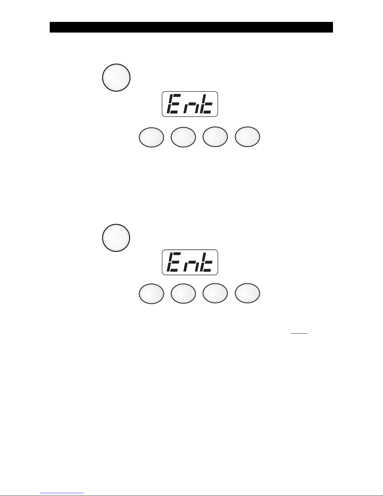
1. Press . The Control Station will display:
2. Enter passcode: .
The Armed Status Indicator light will turn OFF.
Silencing Alarms
To silence an alarm:
1. Press . The Control Station will display:
2. Enter passcode:
Silencing an alarm quickly may prevent a false alarm from being
reported to the authorities. If the Armed Status Indicator light is
NOT
flashing, you can stop the false alarm from being reported. If the
Armed Status Indicator light is flashing, then the false alarm has been
reported and you need to contact the Central Station. When you
silence an alarm that has been reported, the Control Station will go
into Alarm Memory mode (see Alarm Conditions - Alarm Memory).
OPERATING YOUR SYSTEM
OFF
CANCEL
OFF
CANCEL
Page 11
11
OPERATING YOUR SYSTEM
System Not Ready
1. Press the View Info key (Key #1) repeatedly to view zones not
ready. The Control Station will alternate between displaying the
zone condition and the zone number. See Protection Zones for a
list of zone numbers and descriptions.
2. Secure zones not ready. If you cannot secure a zone or do not
want to secure a zone, you may still turn the system ON by
bypassing the zone. See Optional Features - Bypass and Force
Arming.
Changing The Security Level
From the STAY or NIGHT mode
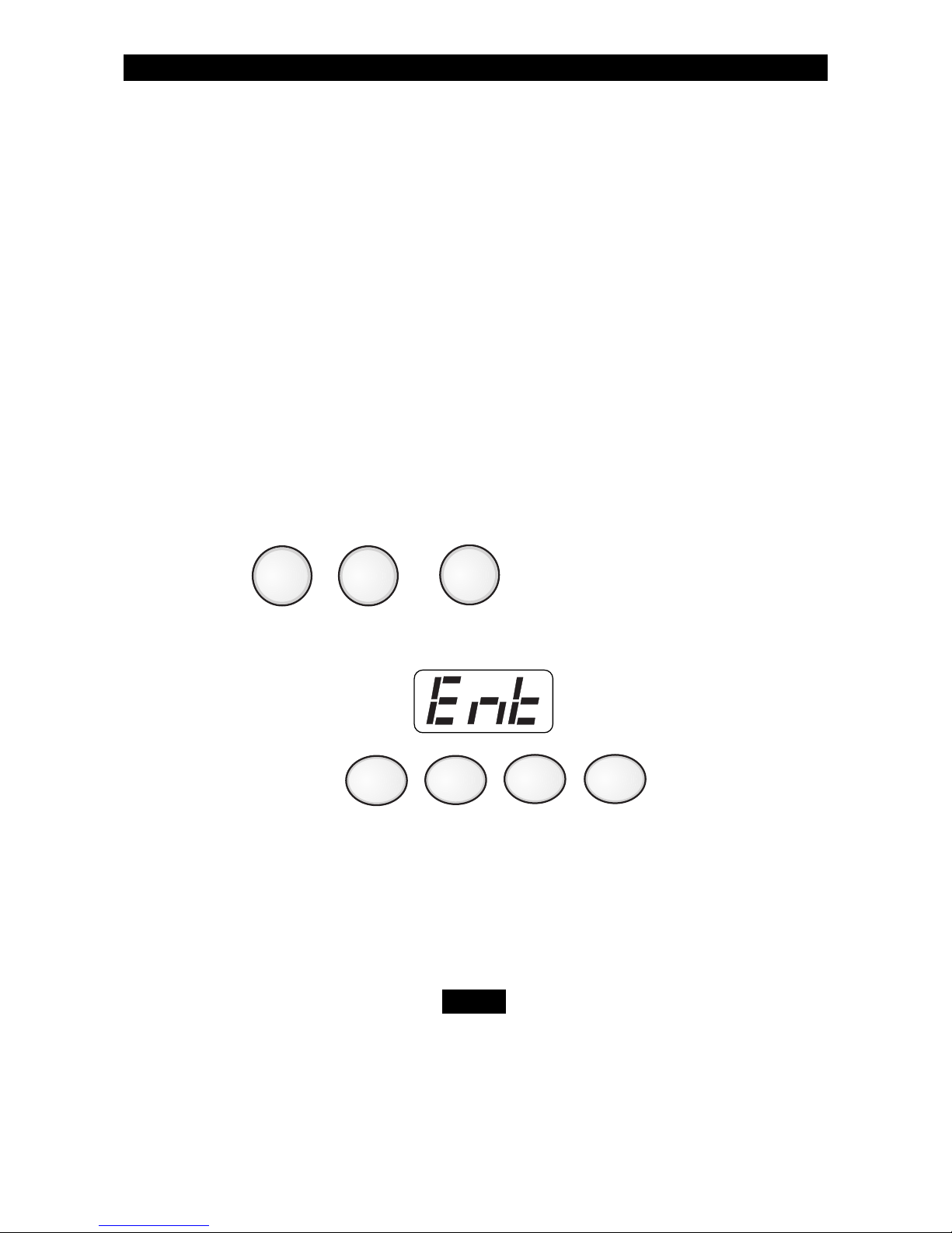
1. Press , or .
The Control Station will display:
2. Enter passcode: .
3. The Control Station will then begin exit countdown time. It is safe to
exit the building during the countdown time. If you exit during the
last 10 seconds of countdown time, the timer will restart the countdown once. If you turn your system ON in the AWAY mode and you
do not exit, the countdown will begin again only once so that you
may exit.
When the system is turned ON in the STAY or NIGHT
mode, you can switch between these modes as often
as you wish without turning your system OFF. When
the system is turned ON in the AWAY mode, you must
turn your system OFF first before you can change
security levels.
AWAY
NIGHT
STAY
NOTE
Page 12

12
OPERATING YOUR SYSTEM
Chime
To enable or disable a “Chime” sound whenever an exterior window or
door zone is opened:
1. Press . Control Station will display:
2. Enter passcode: .
The Control Station will display whether the chime was turned ON or if
it was turned OFF.
Printing The Event Log - (ZX400/ZX410 only)
The Event Log is a record of the activities of your security system. You
may print the Event Log if you have a printer attached.
To print the Event Log:
1. Press .
2. Enter passcode: .
6
3
Page 13
13
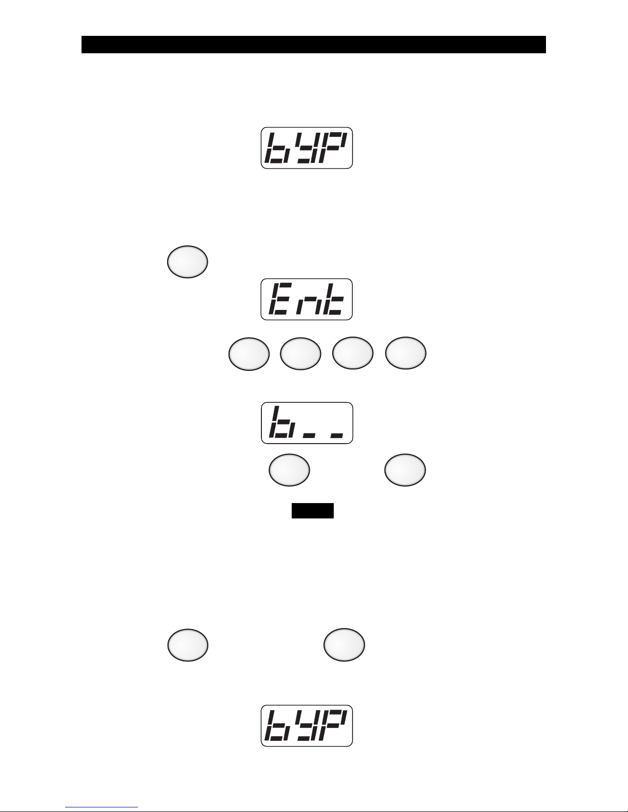
This feature allows you to turn your system ON with one or more zones
intentionally left unprotected until the system is turned OFF.
Bypassed zones are unprotected and will not cause
an alarm if opened while your system is ON.
Group Bypass - (to intentionally bypass all open zones)
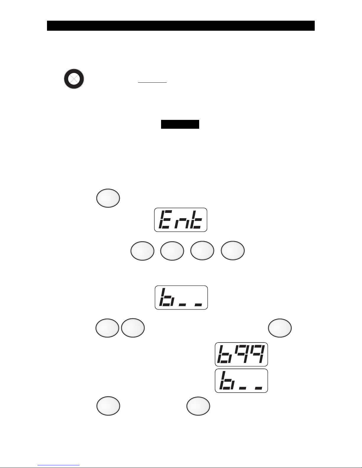
1. Press . The Control Station will display:
2. Enter passcode: .
The Control Station will display:
3. Press to bypass all open zones, then press .
The Control Station will briefly display:
then return to the zone selection display:
4. Press to save changes or to cancel any changes
made.
Optional Features
Bypass - (DO NOT enable for UL Listed Systems)
OPTIONAL FEATURES
O
P
T
I
O
N
E
N
A
B
L
E
D
WARNING
4
9
CLEAR
ENTER
9
ENTER
Page 14
14
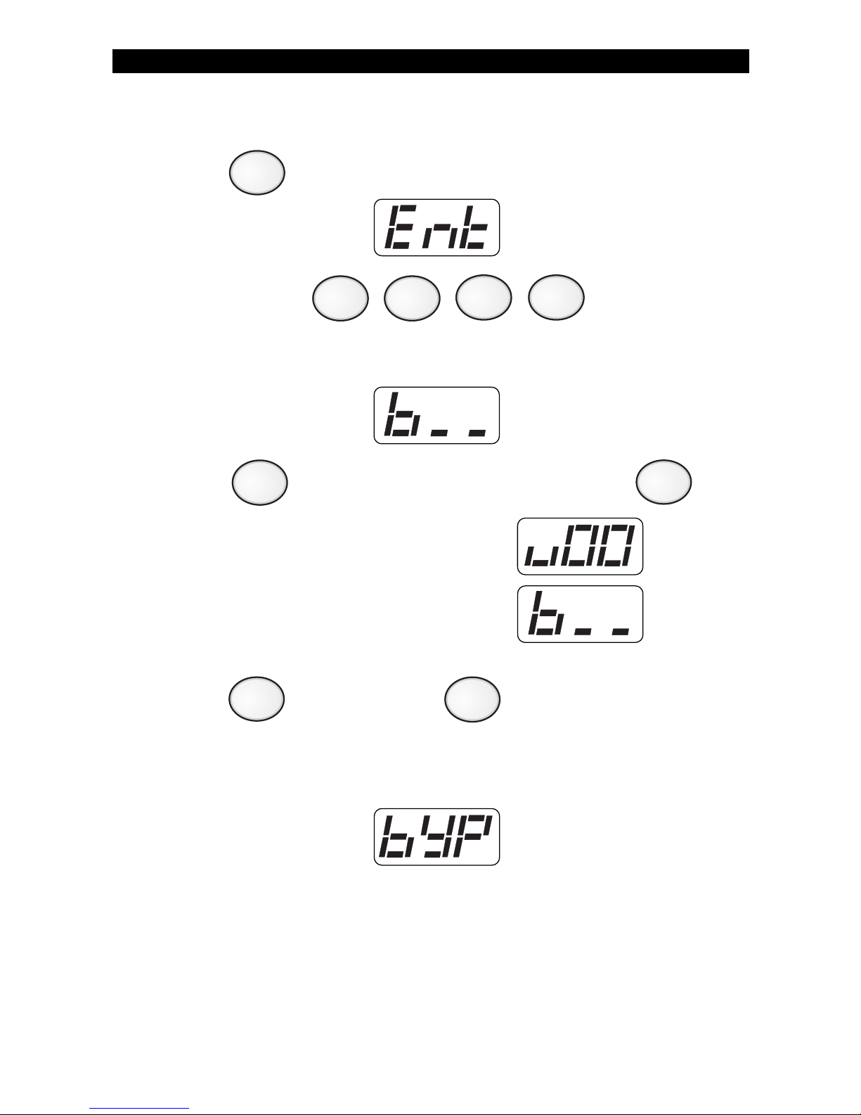
After saving any changes, the Control Station will return to the
READY prompt after briefly displaying:
Selective Bypass/Unbypass -
1. Press . The Control Station will display:
2. Enter passcode: .
The Control Station will display:
3. Enter the zone number , then press .
A letter ‘b’ in front of the zone number indicates that
the zone was bypassed. A letter ‘u’ in front of the
zone number indicates that the zone was unbypassed.
Repeat step 3 for each zone you wish to bypass or unbypass. See
Protection Zones for a list of zone numbers and descriptions.
4. Press to save changes or to cancel changes.
After saving any changes, the Control Station will return to the
READY prompt after briefly displaying:
OPTIONAL FEATURES
(to intentionally bypass/unbypass
a specific zone)
4
CLEAR
ENTER
NOTE
ENTER
Page 15
15
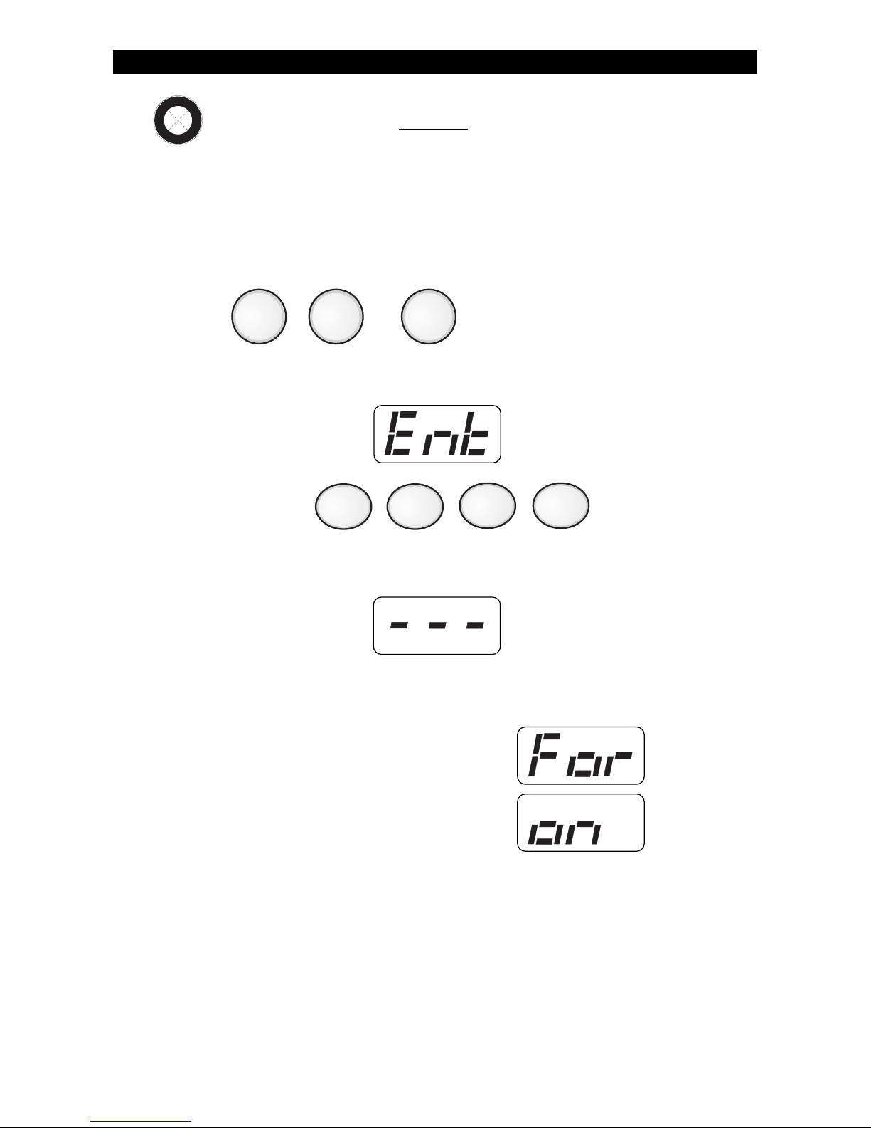
Removing Bypass
1. Press . The Control Station will display:
2. Enter passcode: .
The Control Station will display:
3. Press to unbypass all bypassed zones, then press .
The Control Station will briefly display:
then return to the zone selection display:
4. Press to save changes or to cancel changes.
After saving any changes, the Control Station will return to the
READY prompt after briefly displaying:
OPTIONAL FEATURES
4
0
ENTER
CLEAR
ENTER
Page 16
16
Force-Arming - (DO NOT enable for UL Listed Systems)
OPTIONAL FEATURES
O
P
T
I
O
N
E
N
A
B
L
E
D
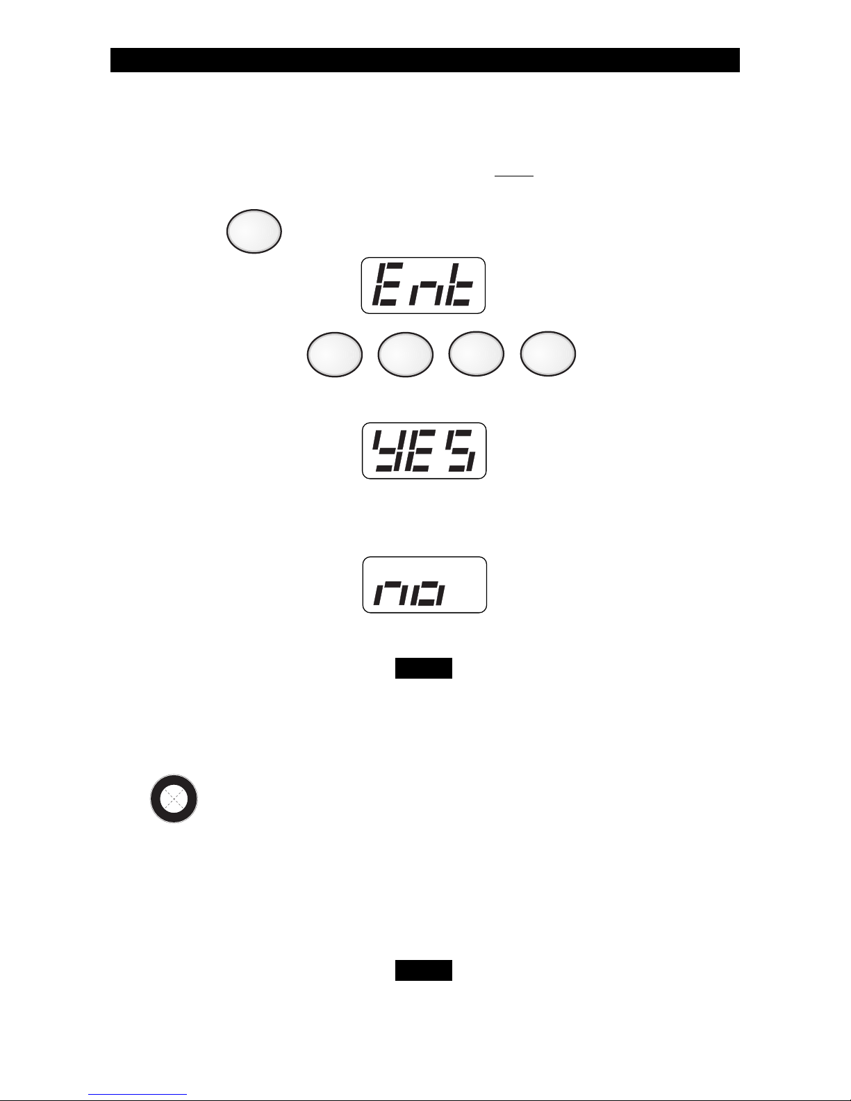
When you turn the system ON with Force-Arming, the system will not
turn ON any zones that are not ready. Once the zone is secured, that
zone is automatically turned ON and will cause an alarm if it is violated.
See Operating Your System - System Not Ready, to identify zones that
are not ready.
1. Press , or .
The Control Station will display:
2. Enter passcode: .
The Control Station will display:
3. Within 5 seconds, press the same key that was pressed in Step 1
above.
The Control Station will display:
then, after the countdown time expires:
AWAY NIGHTSTAY
Page 17

17
Turning Your System ON Using Two Button/
Double Press
Your system may be programmed to quickly turn ON using either the
two button method or the double press method.
The two button method allows you to quickly turn your system ON by
pressing the AWAY, STAY, or NIGHT key and then pressing the Enter
key.
The double press method allows you to quickly turn your system ON by
pressing the AWAY, STAY, or NIGHT key twice.
Exit-ON (ZX400/ZX410 only)
This feature allows your system to turn ON automatically ten (10)
minutes after you leave the premises and no other activity is detected.
Your Control Station will display a visual countdown (an ‘A’ followed by
the number of minutes/seconds) and then sound an audible warning at
two (2) minutes and one (1) minute before the system turns ON. See
ZX400/ZX410 Programming - Cancelling Exit-ON For Today for
instructions on how to cancel this feature for the day.
Automatic-ON - (DO NOT enable for UL Listed Systems)
(ZX400/ZX410 only)
This feature turns your system ON at a scheduled time daily. Your
Control Station will periodically display a visual warning and sound an
audible warning each minute starting at ten (10) minutes before the
system turns ON. See ZX400/ZX410 Programming - Programming the
Automatic-ON Feature and Cancelling Automatic-ON For Today.
OPTIONAL FEATURES
O
P
T
I
O
N
E
N
A
B
L
E
D
O
P
T
I
O
N
E
N
A
B
L
E
D
O
P
T
I
O
N
E
N
A
B
L
E
D
Page 18
18
OPTIONAL FEATURES
Delay Automatic-ON (ZX400/ZX410 only)
To postpone the Automatic-ON for one hour after the audible warning
begins:
1. Press . The Control Station will display:
2. Enter passcode: .
If Automatic-ON has been delayed, the Control Station will display:
If the audible warning for Automatic-ON has not started, then the
Control Station will display:
You cannot extend the Automatic-ON time past
midnight.
Keyswitch Operation
To turn your system ON/OFF or to silence an alarm:
1. Insert key,
2. Turn key and hold for a second,
3. Remove key.
If key is used to turn the system ON, the system will
be turned ON in the AWAY mode only.
5
NOTE
O
P
T
I
O
N
E
N
A
B
L
E
D
NOTE
Page 19
19
Access Output (This system is not UL Listed for Access Control)
To activate an access output device or door strike:
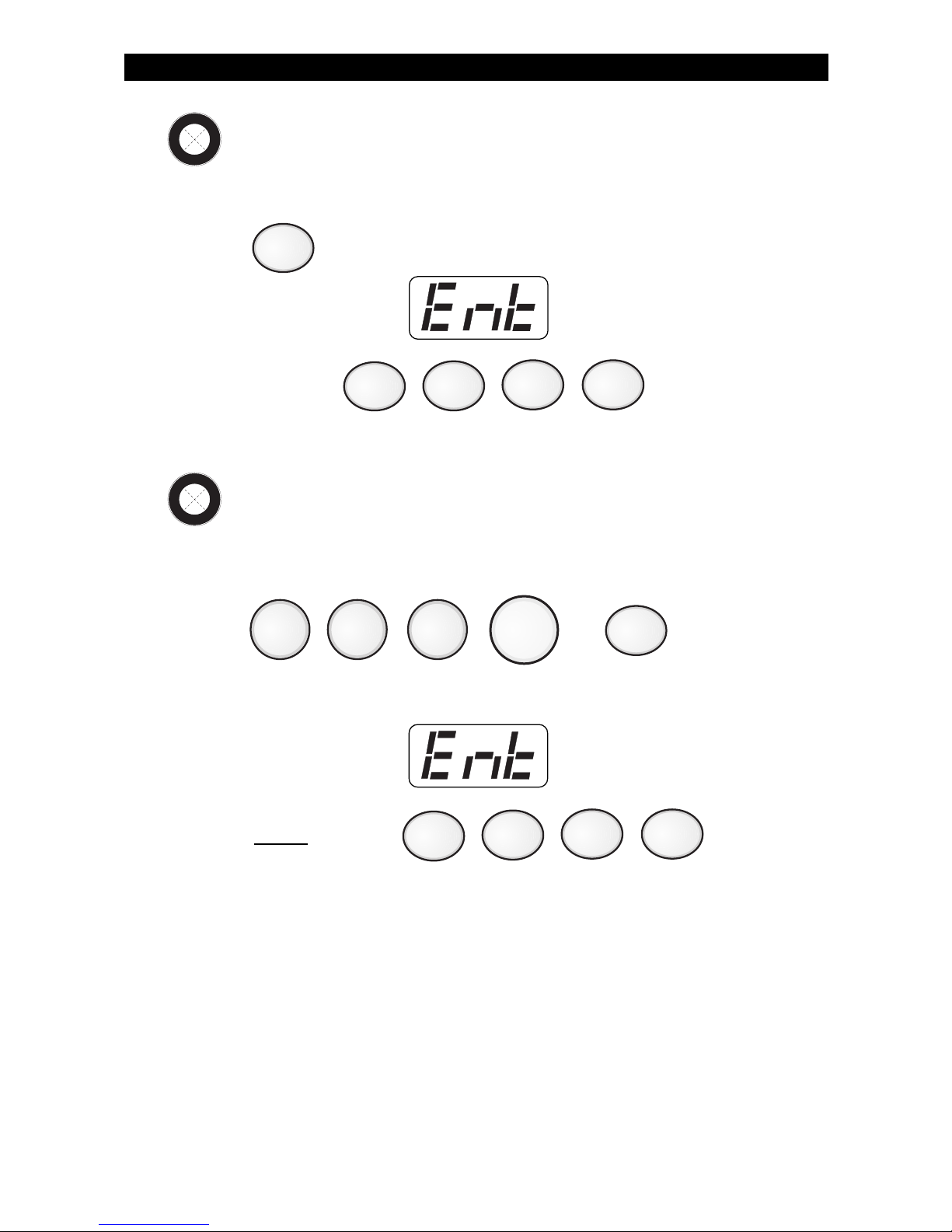
1. Press . The Control Station will display:
2. Enter passcode: .
Duress
To send a silent alarm signal:
1. Press , , , , or .
The Control Station will display:
2. Enter
Duress Passcode: .
OPTIONAL FEATURES
0
O
P
T
I
O
N
E
N
A
B
L
E
D
O
P
T
I
O
N
E
N
A
B
L
E
D
0
OFF
CANCEL
AWAY STAY NIGHT
Page 20

20
OPTIONAL FEATURES
Panic Keys
To activate a panic key, you must press and hold the panic key for three
(3) seconds. On the ZX400/ZX410, you have the option of pressing the
panic key twice within 1 second. Double press is not available on the
ZX200/ZX210. Ask your Security Company Representative how your
panic keys are enabled. See System Reference Guide for a listing of
which Control Stations have the panic keys enabled and the sound for
each key.
An audible alarm may result. To silence the alarm,
press the Off Cancel key and then enter your
passcode.
User On Premise
When a User On Premise passcode is used to activate an access output,
disarm, or silence an alarm, notification will be reported to the Central
Station or to a pager. See your Security Company Representative for
more details.
Fire
Police
(Hold Up)
Medical
(Auxiliary)
NOTE
O
P
T
I
O
N
E
N
A
B
L
E
D
Page 21
21
OPTIONAL FEATURES
O
P
T
I
O
N
E
N
A
B
L
E
D
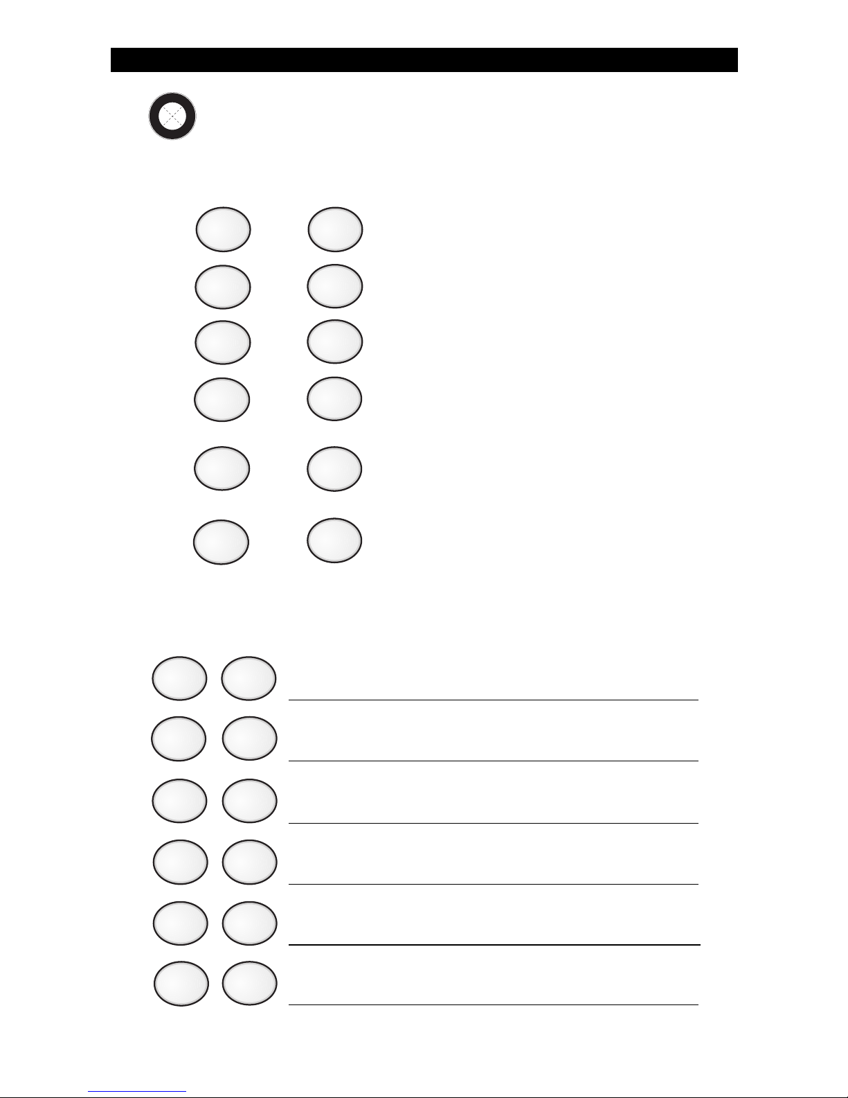
Secondary Function Keys (ZX400/ZX410 only)
Your system may have secondary function keys available. See your
Security Company Representative for complete details. To activate:
Press then to turn the Lamp Trigger OFF/ON.
Press then to turn the Universal Output OFF/ON.
Press then for quick access.
Press then to turn an output OFF/ON (ex: room
light).
Press then to turn an output OFF/ON (ex: basement
light).
Press then to turn an output OFF/ON (ex: lamp or
television).
1
2
3
4
5
6
ENTER
ENTER
ENTER
ENTER
ENTER
ENTER
1
ENTER
2
ENTER
3
ENTER
4
ENTER
5
ENTER
6
ENTER
Below is the description of what your secondary functions keys are
programmed to do:
Page 22
22
Alarm Conditions
ALARM CONDITIONS
2
Alarm Memory
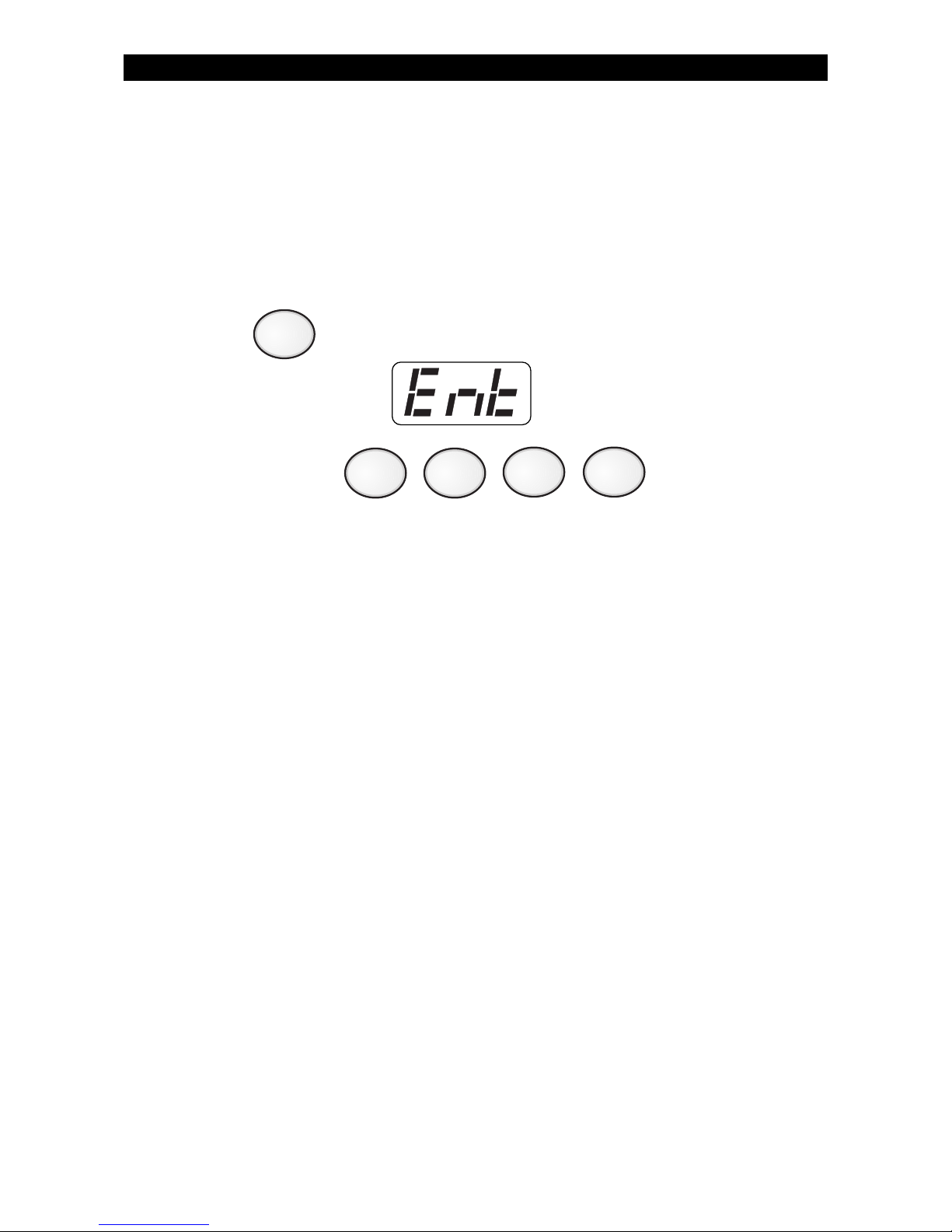
To view zones and keypads that caused an alarm:
1. Press . The Control Station will display:
2. Enter passcode: .
The Control Station display alternates between the most recent zone
(or keypad) number that caused an alarm and the alarm type. If more
than one zone (or keypad) caused an alarm, press the View Info key
(Key #1) repeatedly to view the alarms. See SSD Control Station
Displays & Descriptions.
Page 23
23
Trouble Conditions
TROUBLE CONDITIONS
OFF
CANCEL
NOTE
When your system detects a trouble condition, the Control Station will
light the TROUBLE light and flash the trouble condition message. See
SSD Control Station Displays & Descriptions.
The Control Station will alternate between displaying the system state
(Ready to Arm, etc.) and the trouble message, with each message
displayed for two seconds at a time. If more than one trouble condition is present, then each trouble condition is displayed separately.
Silencing Trouble
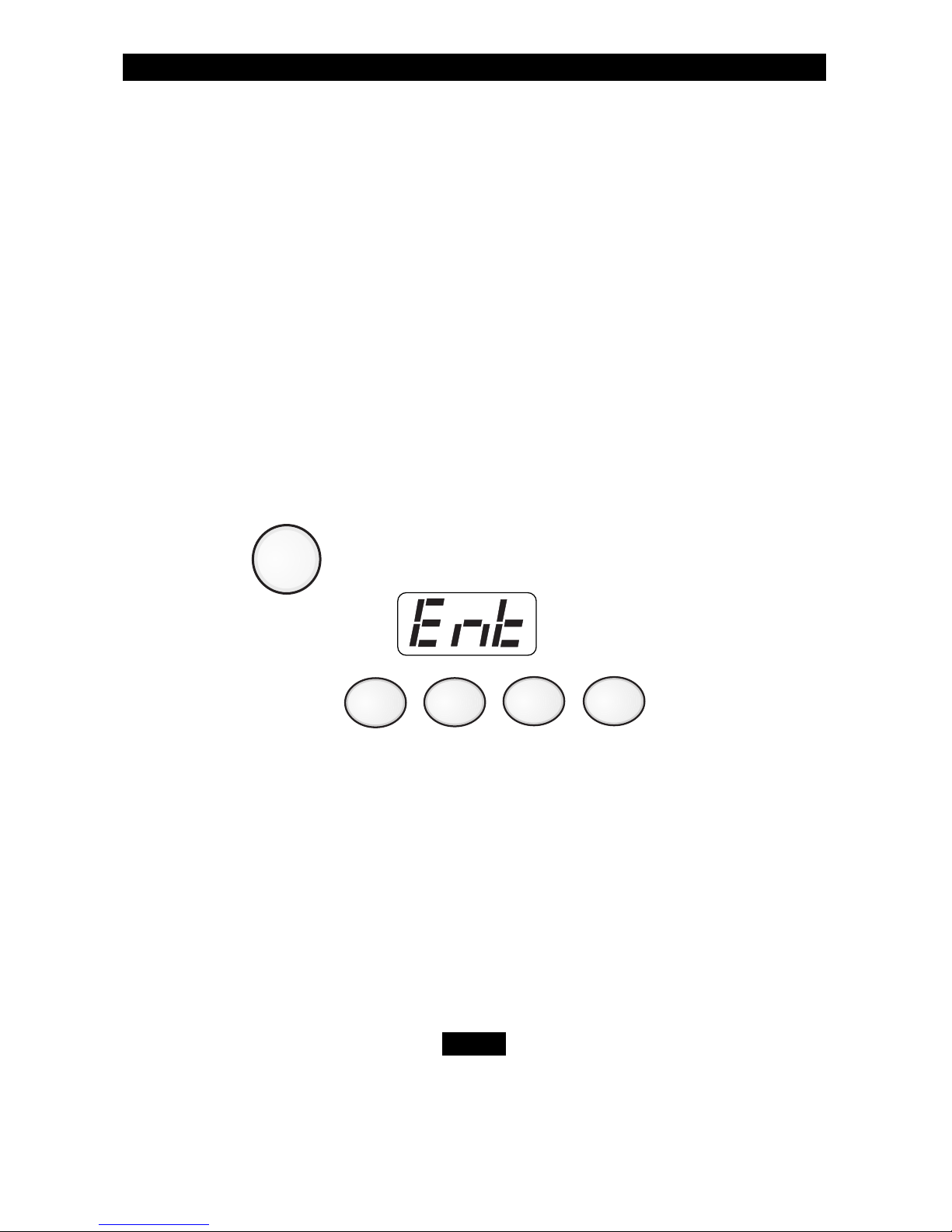
To silence the trouble sounder:
1. Press . The Control Station will display:
2. Enter passcode: .
After you silence the trouble sounder, the trouble light will remain ON.
Identifying Zone Conditions
Press the View Info key (Key #1) repeatedly to display the following
zone conditions that may have occurred: Trouble Zones, Faulted
Zones, and/or Bypassed Zones. The Control Station display will
alternate between the zone condition and the zone number.
If a trouble condition light does not turn OFF, contact
your Security Company Representative.
Page 24

24
1
Testing Your System
Walk Test
To perform a walk test:
1. Press . The Control Station will display:
2. Enter passcode: .
The Control Station will display:
3. Press .
4. Open or activate each sensor. As each sensor is opened, listen for an
audible and visual indication to occur at the Control Station indicating
the sensor is working properly. When all sensors have been opened,
return to the Control Station.
ZX200/ZX210
TESTING YOUR SYSTEM
It is recommended that all tests be performed on a weekly basis. Your
system must be OFF to perform these tests. There are six (6) options
available.
1 Walk Verifies that all system zones are operating properly
2 Battery Verifies that the system battery is fully charged
3 Bell Verifies that the system audibles are operating properly
4 Communicator Verifies that the system communicates with the Central
Station
5 Keypad Verifies that the Control Station lights operate properly
6 RF Signal Strength Tests the signal strength of wireless sensors
(ZX400/ZX410 only)
ZX400/ZX410
8
Page 25
25
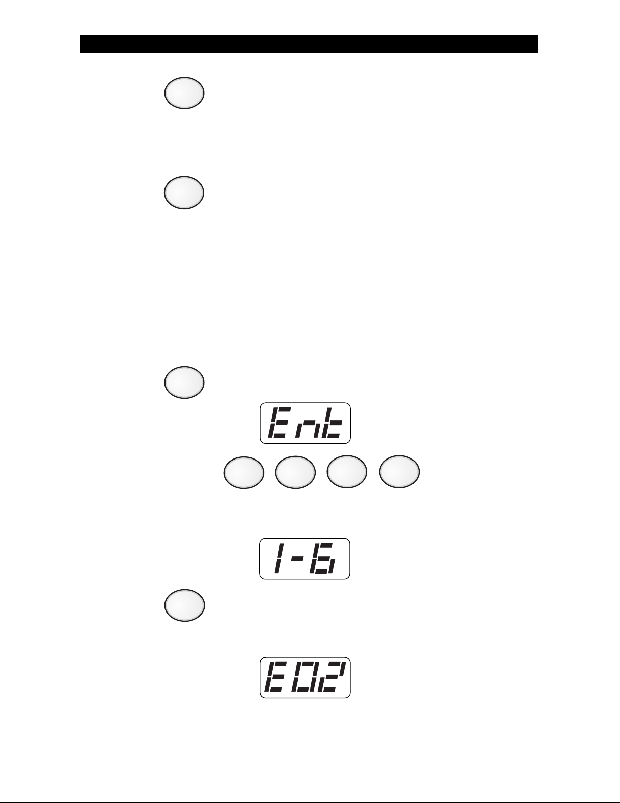
5. Press repeatedly to view any zones that have not been tested.
If you opened a sensor and the Control Station indicates that it was
not tested, it may be faulty. Retest the sensor or contact your Security
Company Representative.
6. Press to quit.
Battery Test
The battery test is used by the Security Company Representative to test
the battery after a new battery has been installed. Your battery is
automatically tested every 15 minutes.
To perform a battery test:
1. Press . The Control Station will display:
2. Enter passcode: .
The Control Station will display:
3. Press .
If a low battery trouble condition occurs, the Control Station will
display:
Contact your Security Company Representative when this condition occurs.
TESTING YOUR SYSTEM
1
2
8
CLEAR
Page 26
26
Bell Test
Notify your neighbors before you test the bell.
To perform a bell test:
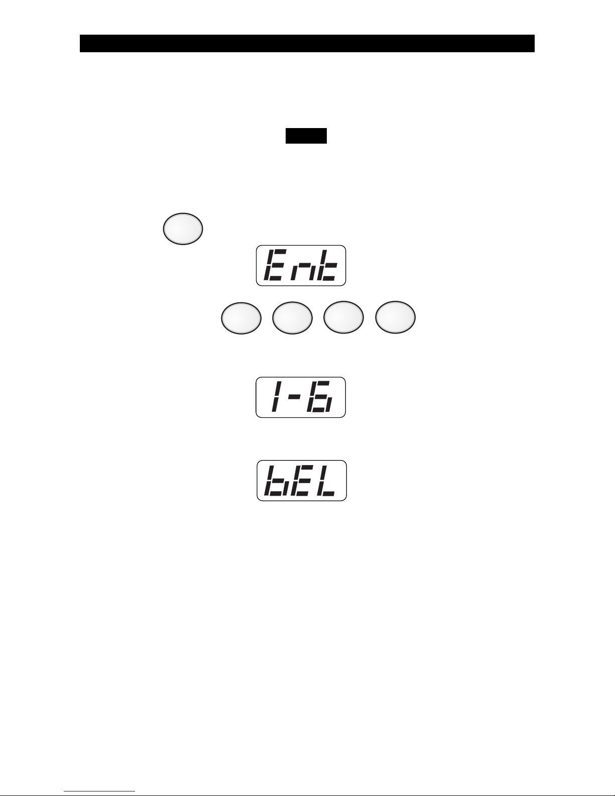
1. Press . The Control Station will display:
2. Enter passcode: .
The Control Station will display:
3. The audible will sound for several seconds. The Control Station will
display:
TESTING YOUR SYSTEM
NOTE
3
Page 27
27
Communicator Test
Your system must be monitored by a Central Station
to perform this test. This test will take a while to
perform.
This test is used to verify that your system is communicating with the
Central Station.
To perform a communicator test:
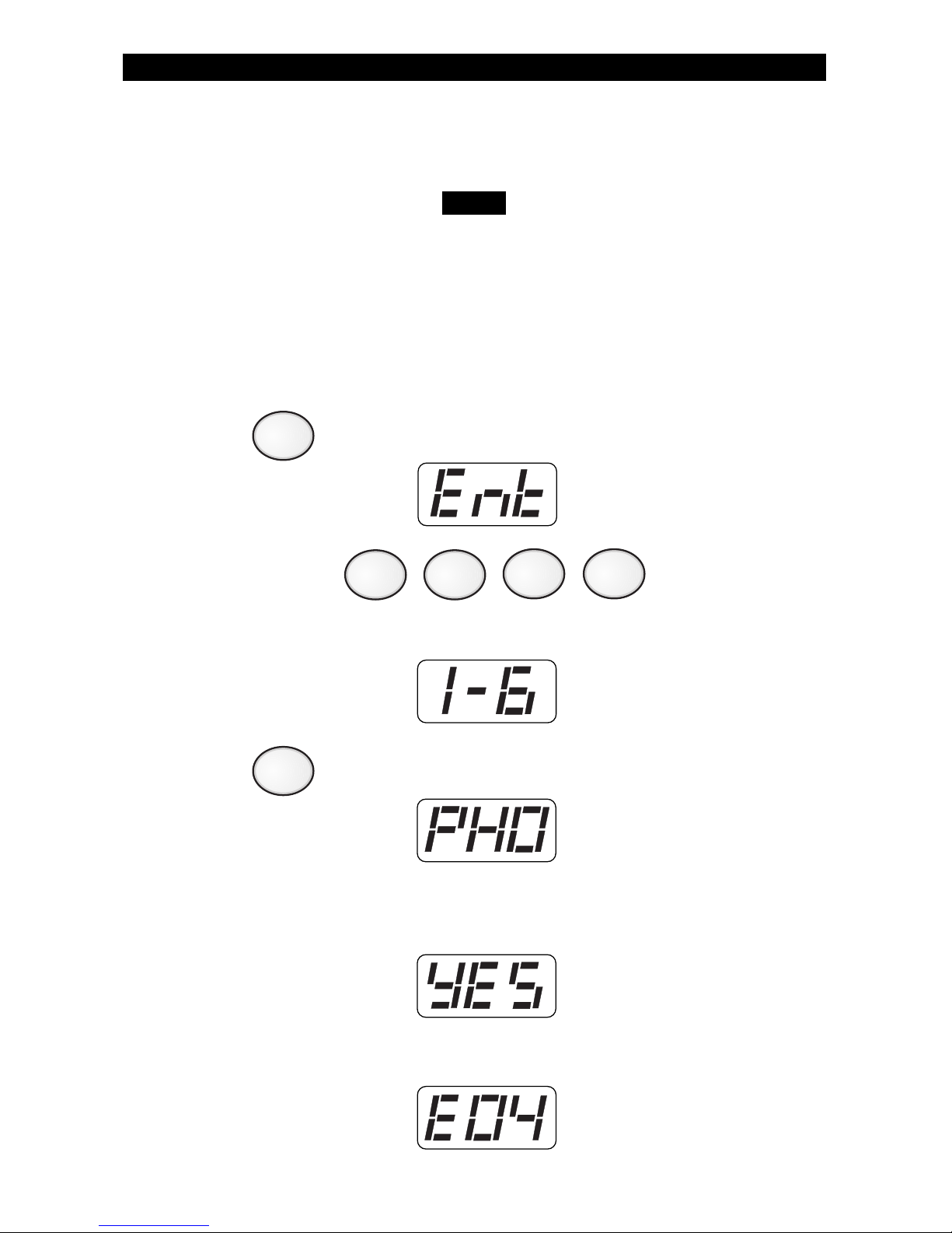
1. Press . The Control Station will display:
2. Enter passcode: .
The Control Station will display:
3. Press . The Control Station will display:
4. If the test passes, the Control Station will sound four (4) beeps
when the test is completed. The Control Station will display:
If the test fails, a Communications Failure trouble condition results
several minutes later. The Control Station will display:
TESTING YOUR SYSTEM
8
NOTE
4
Page 28
28
Keypad Test
To perform a keypad test:
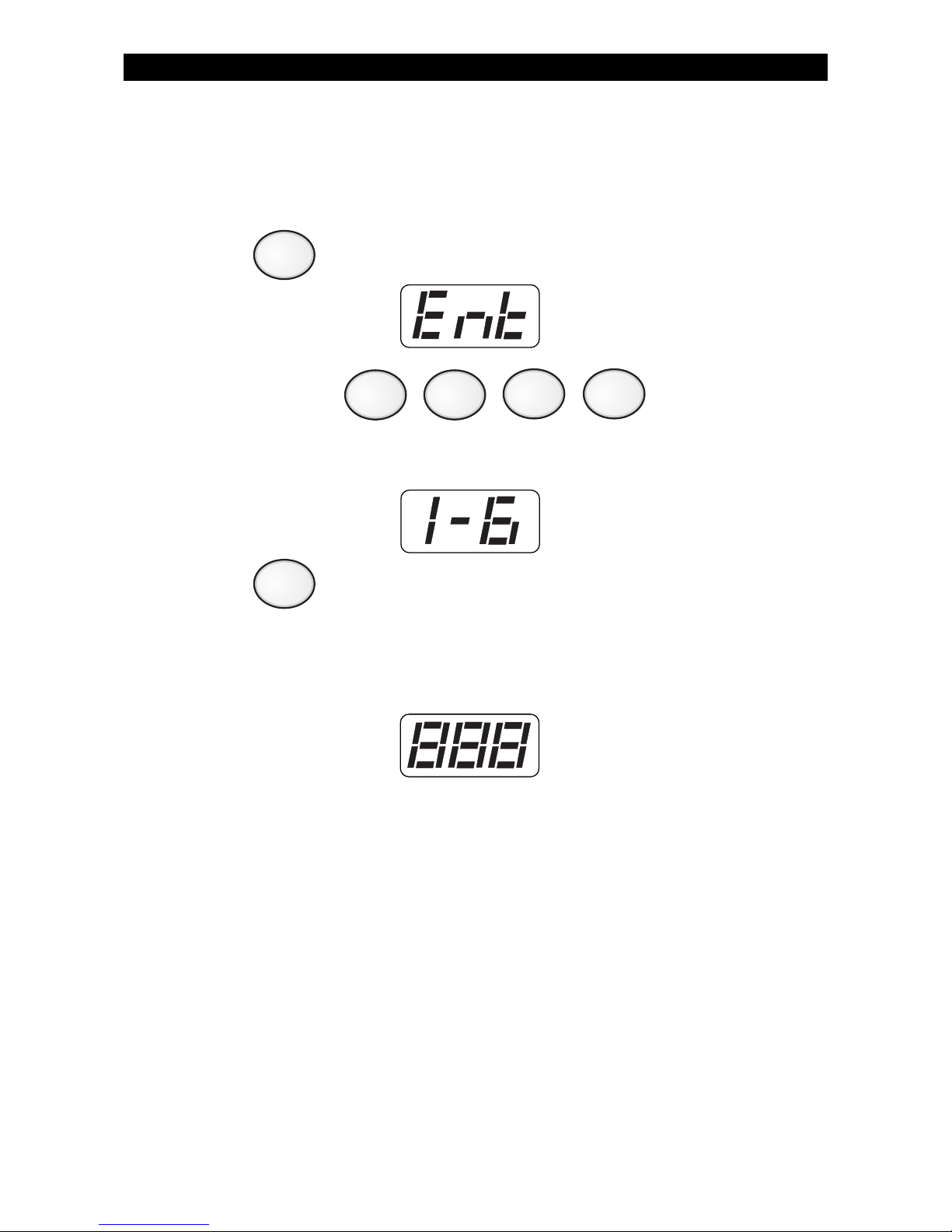
1. Press . The Control Station will display:
2. Enter passcode: .
The Control Station will display:
3. Press .
The Control Station will briefly light all of its indicators (AWAY, STAY,
NIGHT, READY, and TROUBLE) and display:
TESTING YOUR SYSTEM
5
8
Page 29
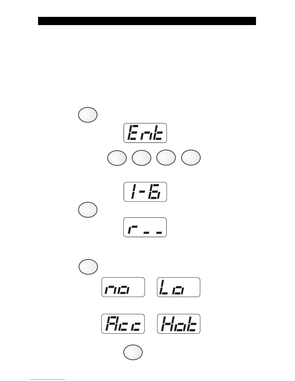
29
TESTING YOUR SYSTEM
RF Signal Strength (ZX400/ZX410 only)
If your system includes wireless sensors, then you can test the strength
of signals from these sensors by performing an RF Signal Strength test.
The strength of a signal can be affected by a low battery condition on
the sensor or changes in the environment due furniture or appliances.
To test the signal strength of selected RF Zones:
1. Press . The Control Station will display:
2. Enter passcode: .
The Control Station will display:
3. Press . The Control Station will display:
4. Enter a number between 13 and 28 to select a wireless sensor to
test. See Protection Zones for a list of zone numbers and descriptions.
Press . The Control Station will briefly display one of the
following:
5. Repeat step 4 or press to exit.
8
6
CLEAR
ENTER
The selected zone is
not RF or is missing
Acceptable
Call your Installation
Representative
Strong
Page 30

30
Remote Connect
Contact your Security Company Representative for instructions.
Programming the User Passcodes
Your system may be programmed with up to 9 user passcodes. Consult
your Security Company Representative as to which passcodes have
been enabled and what Authority Level has been assigned to each one.
To program User Passcodes:
1. Press . The Control Station will display:
2. Enter passcode: .
The Control Station will display:
ZX200/ZX210 Programming
Your system has several features which you may be able to program
yourself. DO NOT attempt to program the system unless you have
been properly trained on programming procedures and you fully
understand these operations. There are two (2) options available:
ZX200/ZX210 PROGRAMMING
1 Remote Connect Allows the installer to program and diagnose
problems from a remote site using the
telephone lines.
2 Program User Codes Allows you to change any passcodes.
9
Page 31
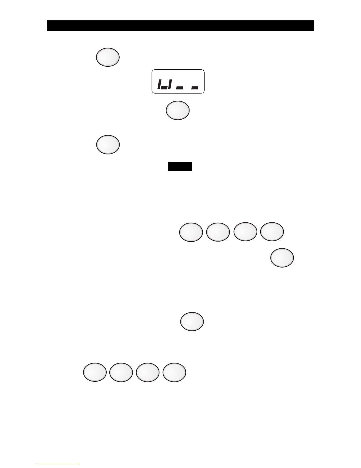
31
3. Press . The Control Station will display:
4. Enter the User ID Passcode (1 - 9) that you wish to program/change.
5. Press .
The Control Station will display the first digit of the
selected User ID passcode. As each new number is
selected, the Control Station will display the next
digit that may be accepted or changed.
6. Enter new four-digit passcode: .
Repeat steps 4 - 6 for each passcode to be programmed or press
to return to the Ready mode.
If the new passcode being entered is a duplicate of an existing one, the
Control Station will sound an error tone and return to the first digit
location so you may try again.
To view an existing passcode, press after each digit displayed
until all four digits have been displayed.
If you wish to make a User ID passcode inoperable,
enter as the new four-digit passcode.
CLEAR
ENTER
ZX200/ZX210 PROGRAMMING
2
NOTE
ENTER
0
0 0 0
Page 32
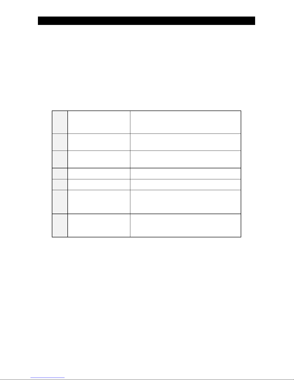
32
Remote Connect
Contact your Security Company Representative for instructions.
ZX400/ZX410 Programming
Your system has several features which you may be able to program
yourself. DO NOT attempt to program the system unless you have
been properly trained on programming procedures and you fully
understand these operations. There are seven (7) options available:
ZX400/ZX410 PROGRAMMING
1 Remote Connect Allows the installer to program and diagnose
problems from a remote site using the
telephone lines.
2 Set Clock Sets the system date and time. (Military
format)
3 Program Automatic-ON Schedules your system to automatically turn
ON at a specific day(s) and time(s).
4 Program Latch Key Monitors entry of a specific passcode.
5 Program User Codes Allows you to change any passcodes.
6 Cancelling Automatic-ON Cancels the system from automatically
turning ON for the scheduled time for that
day only.
7 Cancelling Exit-ON Cancels the system from automatically
turning ON for Today 10 minutes after you
leave the premises for that day only.
For Today
For Today
Page 33
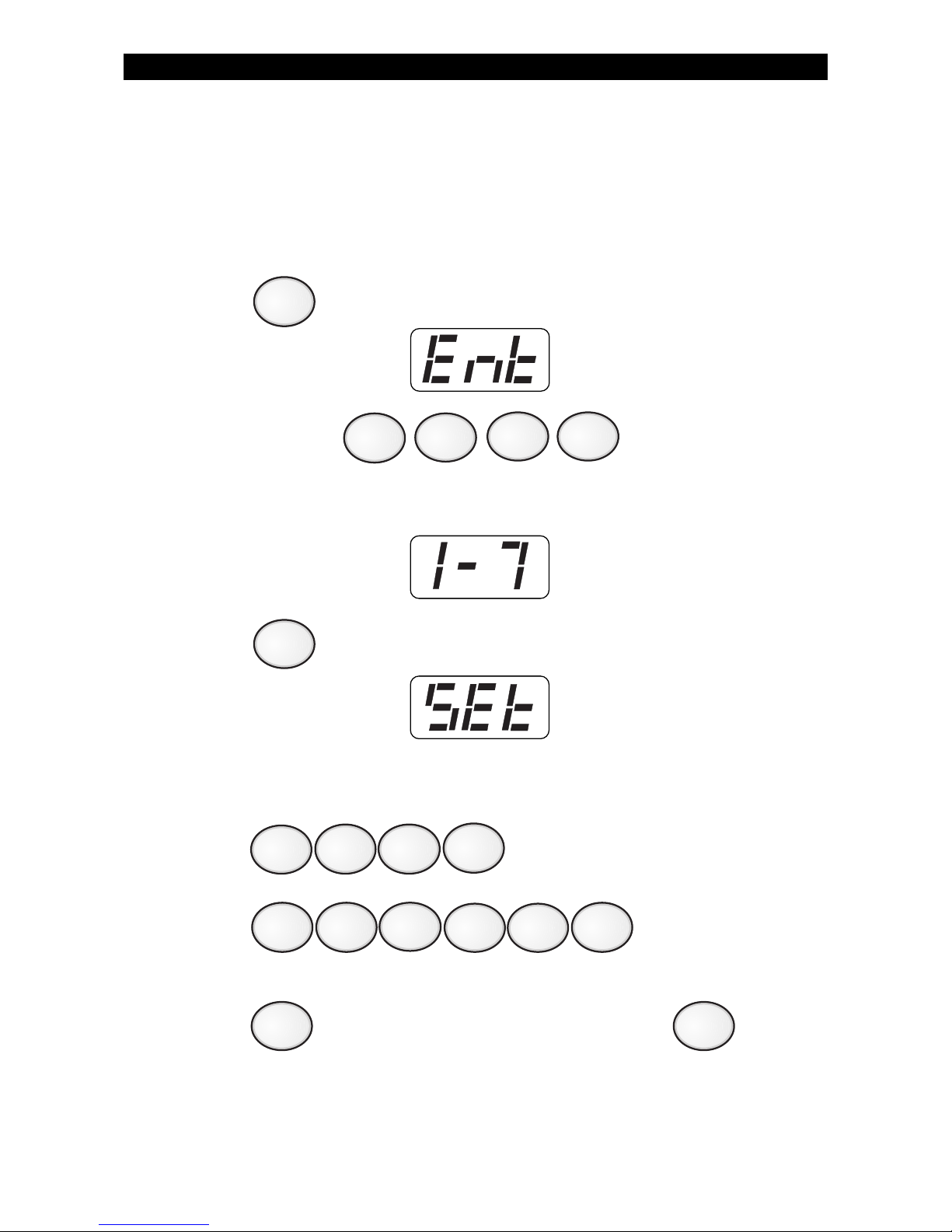
33
Set Clock
The clock is set according to military time (24:00 hours).
To set the clock:
1. Press . The Control Station will display:
2. Enter passcode: .
The Control Station will display:
3. Press . The Control Station will display:
EXAMPLE: To set the clock to 2:15 pm on June 17, 1996:
Press (2:15 pm) .
Press (June 17, 1997) .
4. Press
to start over if a mistake is made or press
to save changes.
ZX400/ZX410 PROGRAMMING
9
2
1
4
5
6
7
1
0
1
9
CLEAR
ENTER
7
Page 34
34
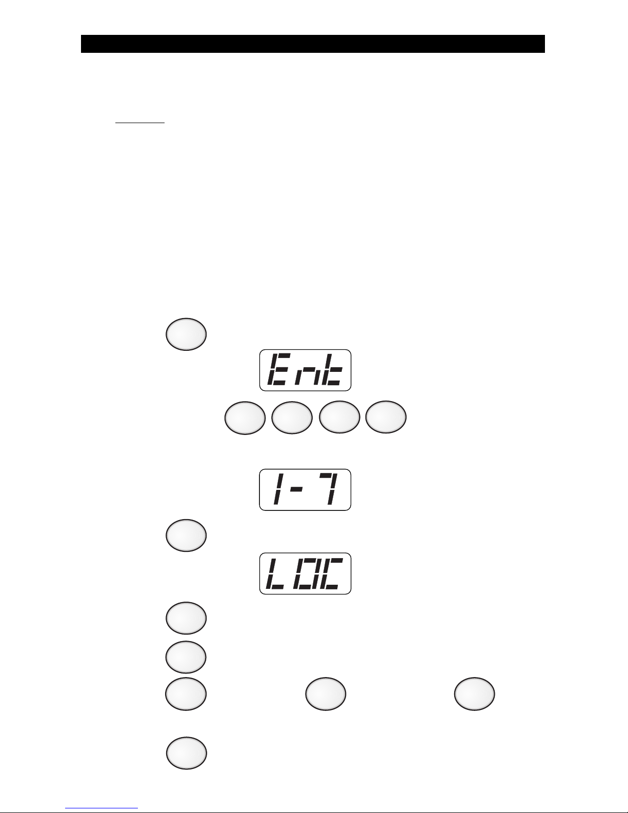
Programming the Automatic-ON Feature
(DO NOT enable for UL Listed Systems)
This feature allows you to automatically turn your system ON at certain
times for certain days. There are four items to be programmed:
A. Setting the Security Level
B. Day(s) of week to automatically turn ON
C. Hour to turn ON each day
D. Minute to turn ON each day
A. Setting the Security Level
To program the Automatic-ON feature:
1. Press . The Control Station will display:
2. Enter passcode: .
The Control Station will display:
3. Press . The Control Station will display:
4. Press (for location 1).
5. Press . The Control Station will display the current setting.
6. Press for AWAY, press for STAY, or press
for NIGHT.
7. Press to save selection and return to the location prompt.
ZX400/ZX410 PROGRAMMING
9
3
1
ENTER
21
0
ENTER
Page 35
35
B. Day(s) To Turn ON
To select the day(s) of the week you want your system to automatically
turn ON, add together the values below for those days selected.
Value Day of the Week
1 Sunday
2 Monday
4 Tuesday
8 Wednesday
16 Thursday
32 Friday
64 Saturday
Example: To have your system automatically turn ON for Monday,
Tuesday, and Saturday, add 2 + 4 + 64. Enter the value 70.
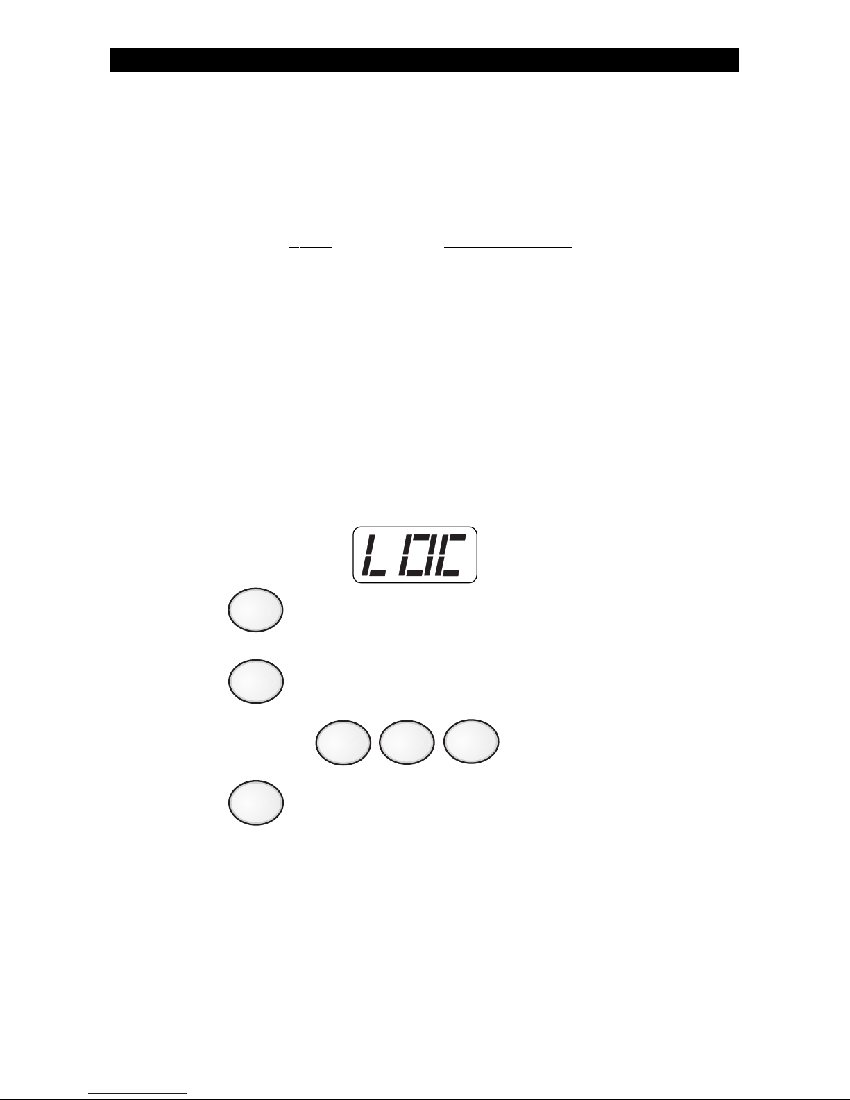
8. The Control Station will display:
Press (for location 2).
9. Press . The Control Station will display the current value.
10. Enter new value: (0 - 127) .
11. Press to save selection and return to the location prompt.
ZX400/ZX410 PROGRAMMING
2
ENTER
ENTER
Page 36
36
C. Hour To Turn ON Each Day
If the time scheduled is from 12:00 am to 12:09 am, the ten minute
warning period will not begin until 12:00 am and will therefore be
less than the set ten minute time period.
The hour to turn ON must be entered, in military format, for each day you
selected. Each day has a corresponding location number.
Location Day of the Week
3 hour on Sunday
5 hour on Monday
7 hour on Tuesday
9 hour on Wednesday
11 hour on Thursday
13 hour on Friday
15 hour on Saturday
Steps 12-15 must be repeated for each day of the
week you selected.
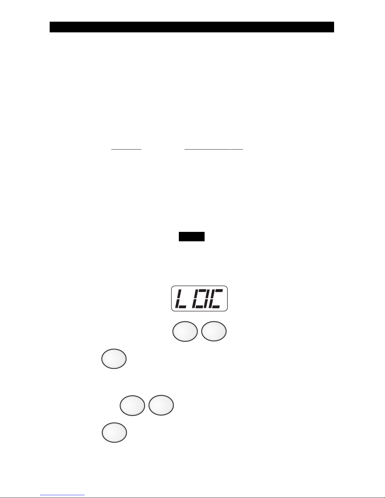
12. The Control Station will display:
Enter the location number from the chart above.
13. Press .
The Control Station will display the current scheduled time.
14. Enter hour where 0 = midnight and 23 = 11:00 pm.
15. Press to save selection and return to the location prompt.
ZX400/ZX410 PROGRAMMING
NOTE
ENTER
ENTER
Page 37
37
D. Minute To Turn ON Each Day
The minute to turn ON must be entered for each day you selected. Each day
has a corresponding location number.
Location Day of the Week
4 minute on Sunday
6 minute on Monday
8 minute on Tuesday
10 minute on Wednesday
12 minute on Thursday
14 minute on Friday
16 minute on Saturday
Steps 16 - 19 must be repeated for each day of the week
you selected.
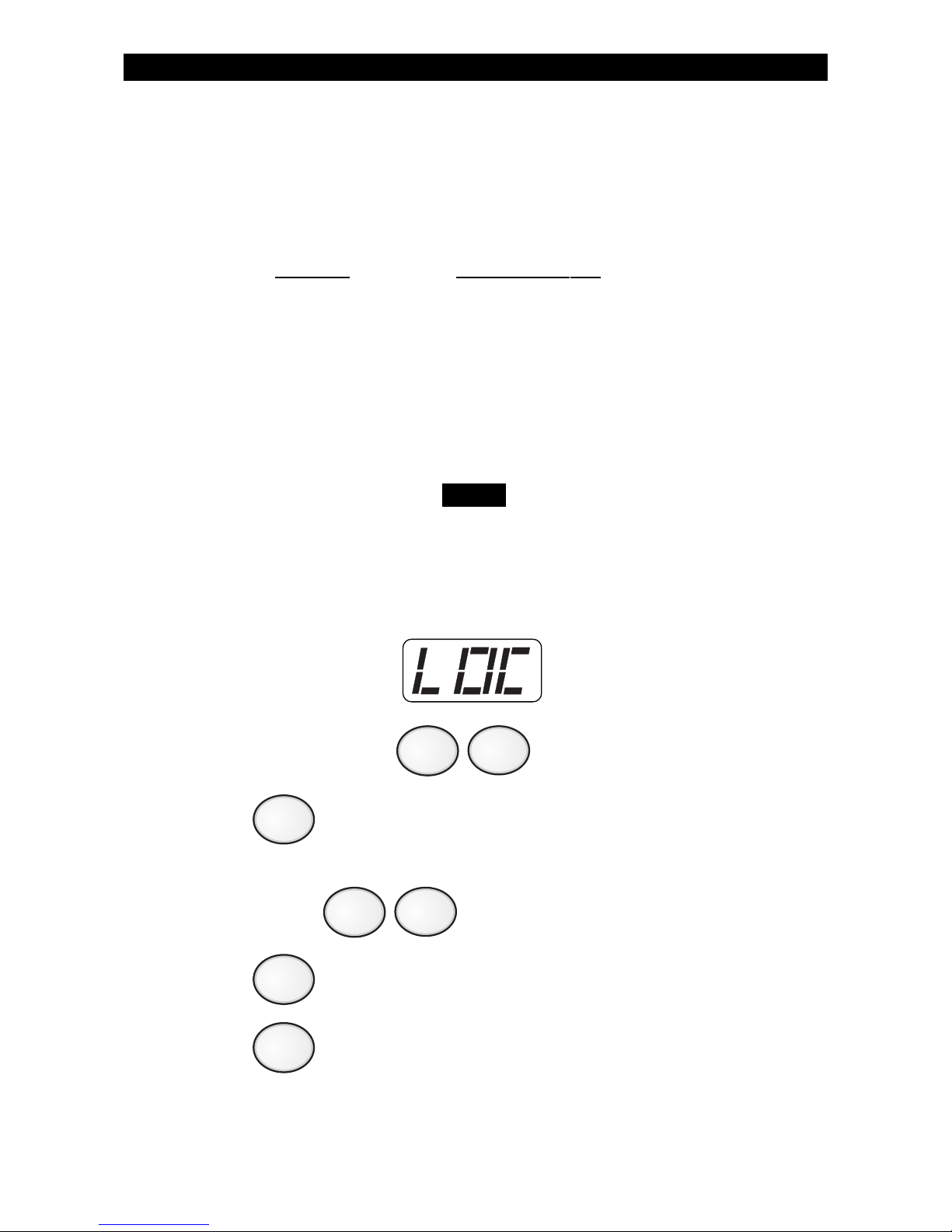
16. The Control Station will display:
Enter location number from chart above.
17. Press . The Control Station will display the current scheduled
time.
18. Enter minute: (0 - 59) .
19. Press to save selection and return to the location prompt.
20. Press to return to the ready mode.
ZX400/ZX410 PROGRAMMING
NOTE
CLEAR
ENTER
ENTER
Page 38
38
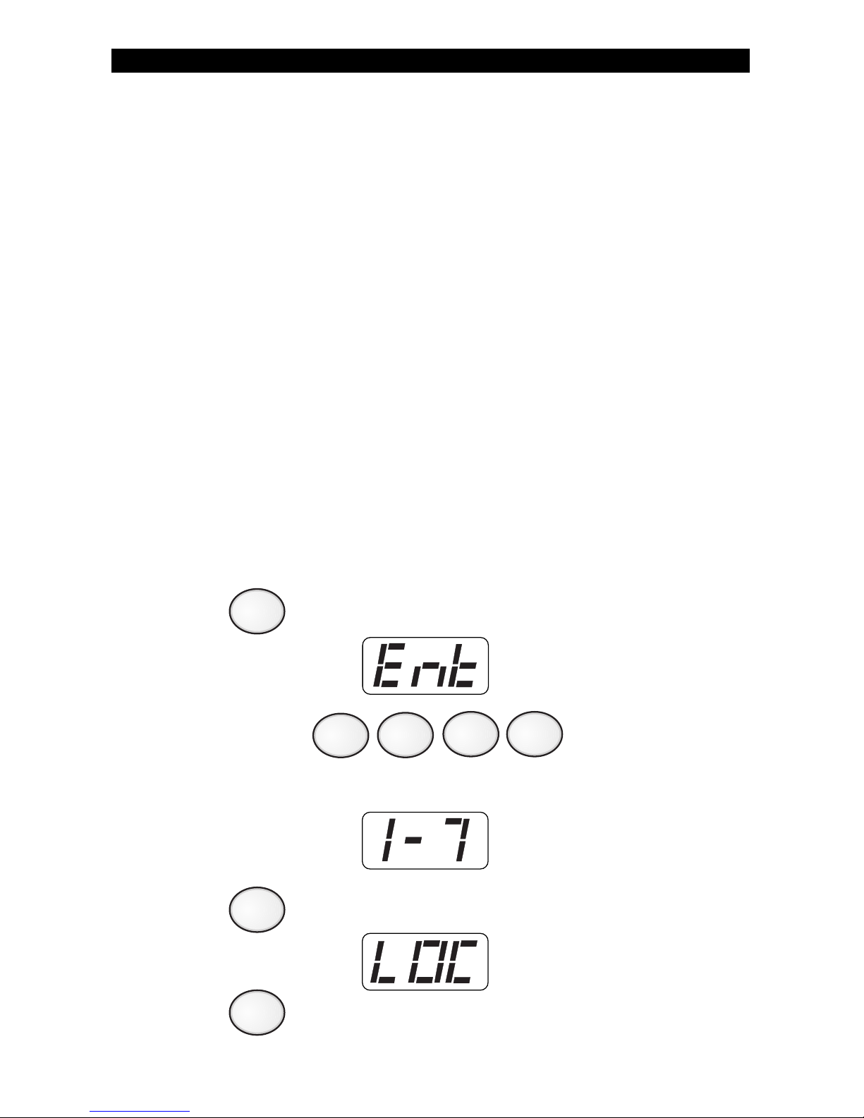
Programming the Latch Key Feature
This feature allows you to monitor the entry of a designated person.
The system will look for that user’s passcode to be used on the selected
day(s) during the programmed time frame. During that time frame,
the Control Station will chime once a minute until that person’s
passcode is entered or the time frame has expired. The system will
send a report if the user’s passcode was not entered during the scheduled time on the scheduled day. Contact your Security Company
Representative for more details.
There are five items to be programmed:
A. Setting the user passcode ID to be monitored
B. Day(s) of week to monitor
C. Time frame for the days that the user passcode must be entered
D. Hour to monitor each day
E. Minute to monitor each day
A. Setting the Latch Key User ID to be Monitored
To program the Latch Key feature:
1. Press . The Control Station will display:
2. Enter passcode: .
The Control Station will display:
3. Press . The Control Station will display:
4. Press (for location 1).
ZX400/ZX410 PROGRAMMING
4
1
9
Page 39
39
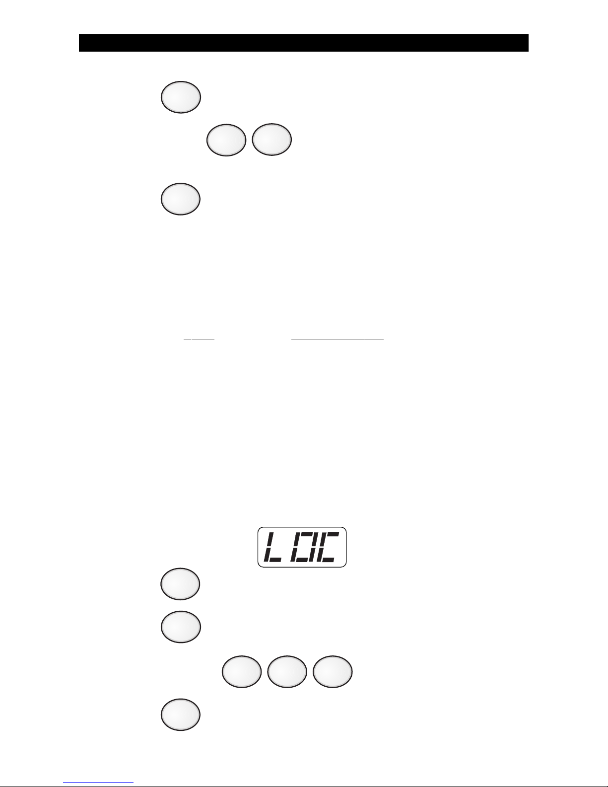
5. Press . The Control Station will display the current setting.
6. Enter User ID (0 - 50, where 0 disables Latch Key
Monitoring).
7. Press to save selection and return to the location prompt.
B. Day(s) of Week to Monitor
To select the day(s) of the week you want to be monitored, add
together the values below for those days selected.
Value Day of the Week
1 Sunday
2 Monday
4 Tuesday
8 Wednesday
16 Thursday
32 Friday
64 Saturday
Example: To set up monitoring for Monday, Wednesday, and Friday,
add 2 + 8 + 32. Enter the value 42.
8. The Control Station will display:
Press (for location 2).
9. Press . The Control Station will display the current setting.
10. Enter new value (0 - 127) .
11. Press to save selection and return to the location prompt.
ENTER
ZX400/ZX410 PROGRAMMING
ENTER
2
ENTER
ENTER
Page 40
40
C. Latch Key Time Window
The latch key time window is the amount of time in minutes, before
and after the scheduled time, that the selected user has to enter the
designated passcode. The time frame may be from 0 minutes to 255
minutes.
The Latch Key Time Window cannot cross over the
midnight boundary.
Example: If the scheduled time is 3:00 pm and the time frame given to
enter the passcode is from 2:30 pm until 3:30 pm, you need
to enter a value of 30.
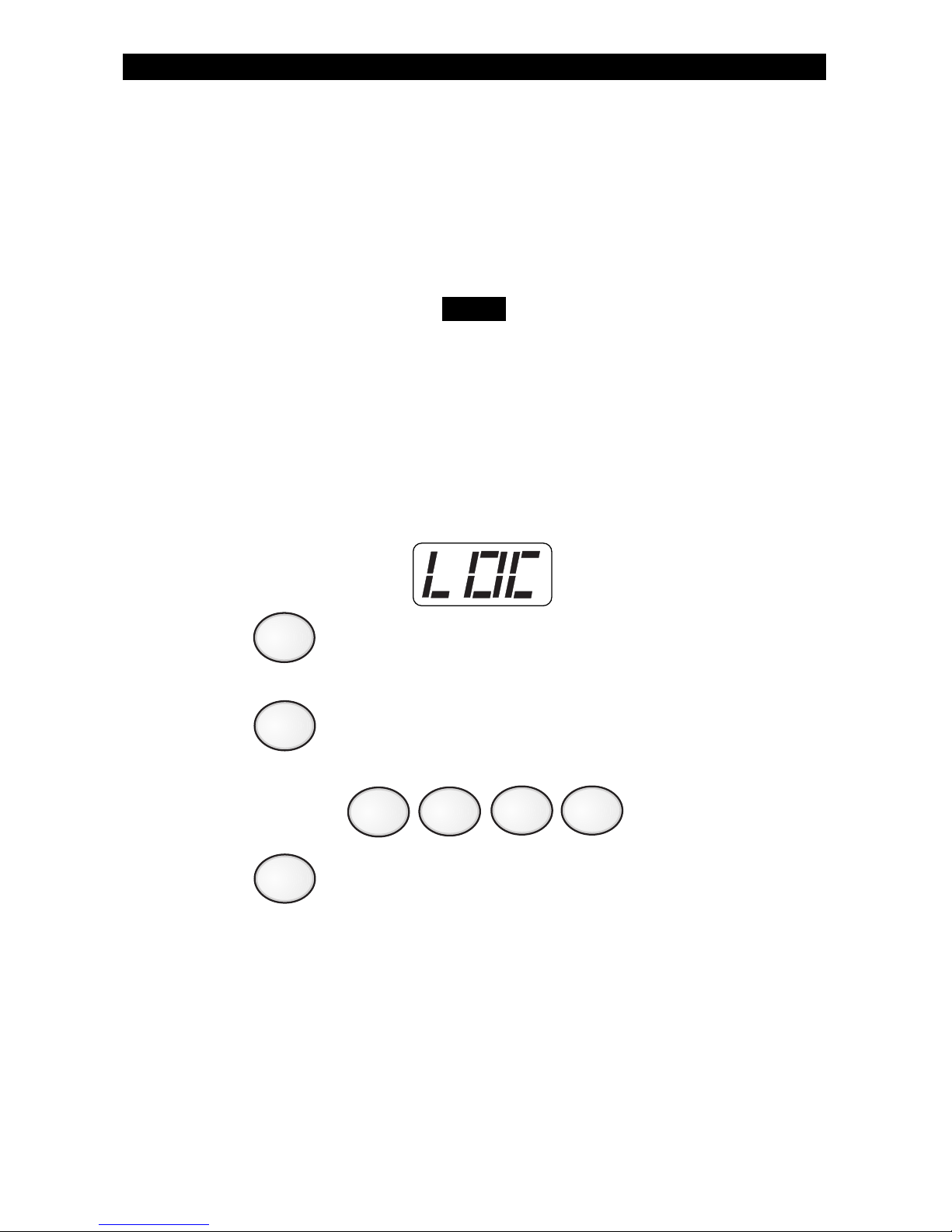
12. The Control Station will display:
Press (for location 3).
13. Press . The Control Station will display the current sched-
uled time.
14. Enter new value (0 - 255) .
15. Press to save selection and return to the location prompt.
ZX400/ZX410 PROGRAMMING
NOTE
3
ENTER
ENTER
Page 41
41
D. Hour To Be Monitored For Each Day
The monitoring hour must be entered, in military format, for each day
you selected. Each day has a corresponding location number.
Location Number Day of the Week
4 hour on Sunday
6 hour on Monday
8 hour on Tuesday
10 hour on Wednesday
12 hour on Thursday
14 hour on Friday
16 hour on Saturday
Steps 16-19 must be repeated for each day of the
week you selected.
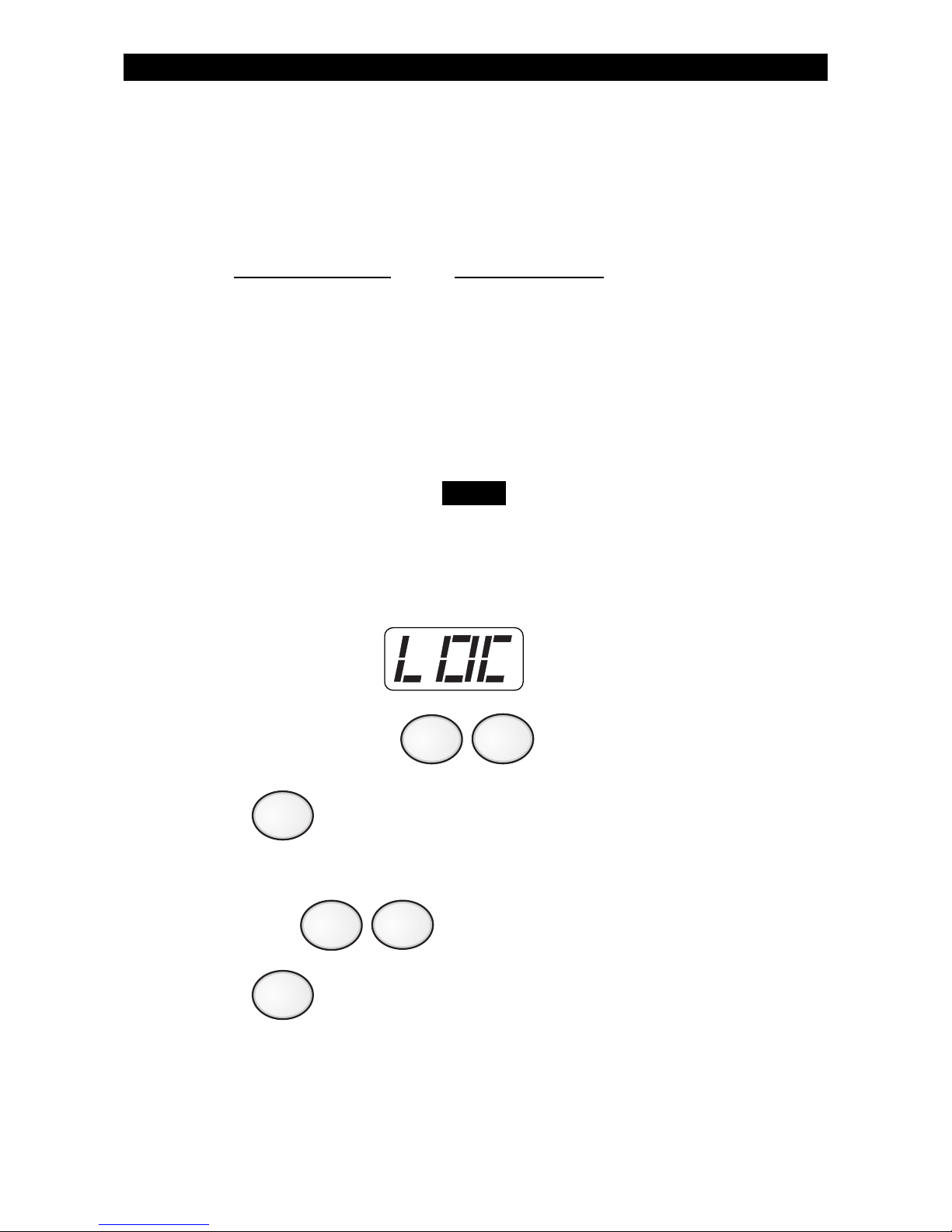
16. The Control Station will display:
Enter location number from chart above.
17. Press . The Control Station will display the current sched-
uled time.
18. Enter hour where 0 = midnight and 23 = 11:00 pm.
19. Press to save selection and return to the location prompt.
ZX400/ZX410 PROGRAMMING
NOTE
ENTER
ENTER
Page 42
42
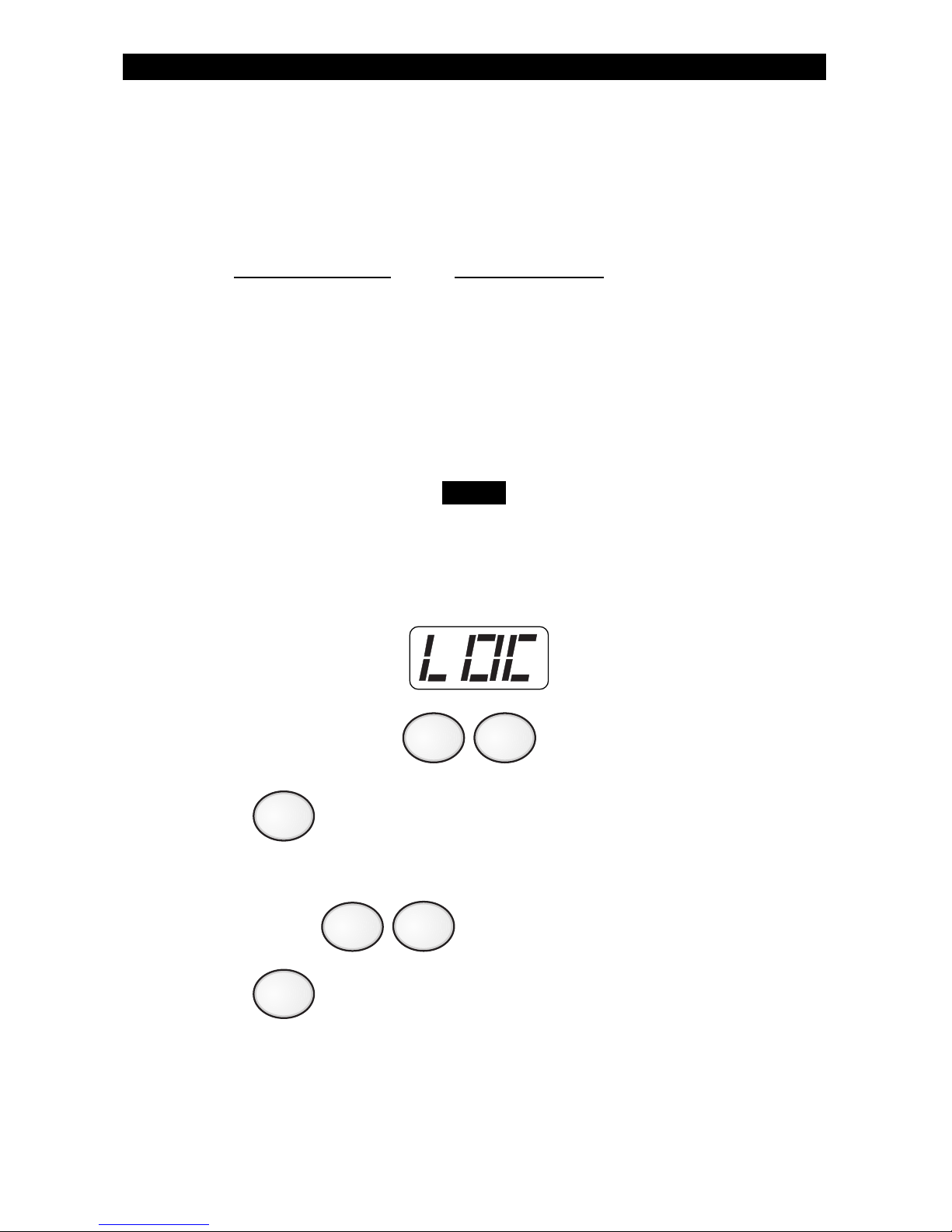
E. Minute To Be Monitored For Each Day
The monitoring minute must be entered for each day you selected.
Each day has a corresponding location number.
Location Number Day of the Week
5 minute on Sunday
7 minute on Monday
9 minute on Tuesday
11 minute on Wednesday
13 minute on Thursday
15 minute on Friday
17 minute on Saturday
Steps 20-23 must be repeated for each day of the
week you selected.
20. The Control Station will display:
Enter location number from chart above.
21. Press . The Control Station will display the current sched-
uled time.
22. Enter minute (0 - 59).
23. Press to save selection and return to the location prompt.
ZX400/ZX410 PROGRAMMING
NOTE
ENTER
CLEAR
Page 43
43
Programming the User Passcodes
Your system may be programmed with up to 50 user passcodes.
Consult your Security Company Representative as to which passcodes
have been enabled and what Authority Level has been assigned to each
one.
To program User Passcodes:
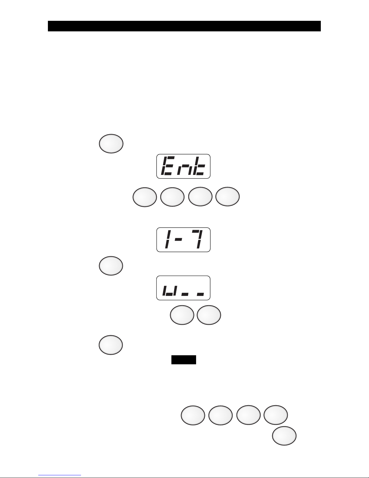
1. Press . The Control Station will display:
2. Enter passcode: .
The Control Station will display:
3. Press . The Control Station will display:
4. Enter the User Passcode ID (1 - 50) that you wish
to program/change.
5. Press .
The Control Station will display the first digit of the
selected User ID passcode. As each new number is
selected, the Control Station will display the next digit
that may be accepted or changed.
6. Enter new four-digit passcode .
Repeat steps 4 - 6 for each passcode to be programmed or press
to return to the Ready mode.
ZX400/ZX410 PROGRAMMING
CLEAR
ENTER
9
NOTE
5
Page 44
44
ZX400/ZX410 PROGRAMMING
ENTER
0
0 0 0
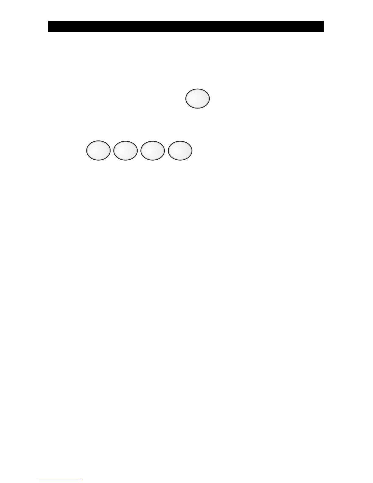
If the new passcode being entered is a duplicate of an existing one, the
Control Station will sound an error tone and return to the first digit
location so you may try again.
To view an existing passcode, press after each digit displayed
until all four digits have been displayed.
If you wish to make a User ID passcode inoperable,
enter as the new four-digit passcode.
Page 45
45
ZX400/ZX410 PROGRAMMING
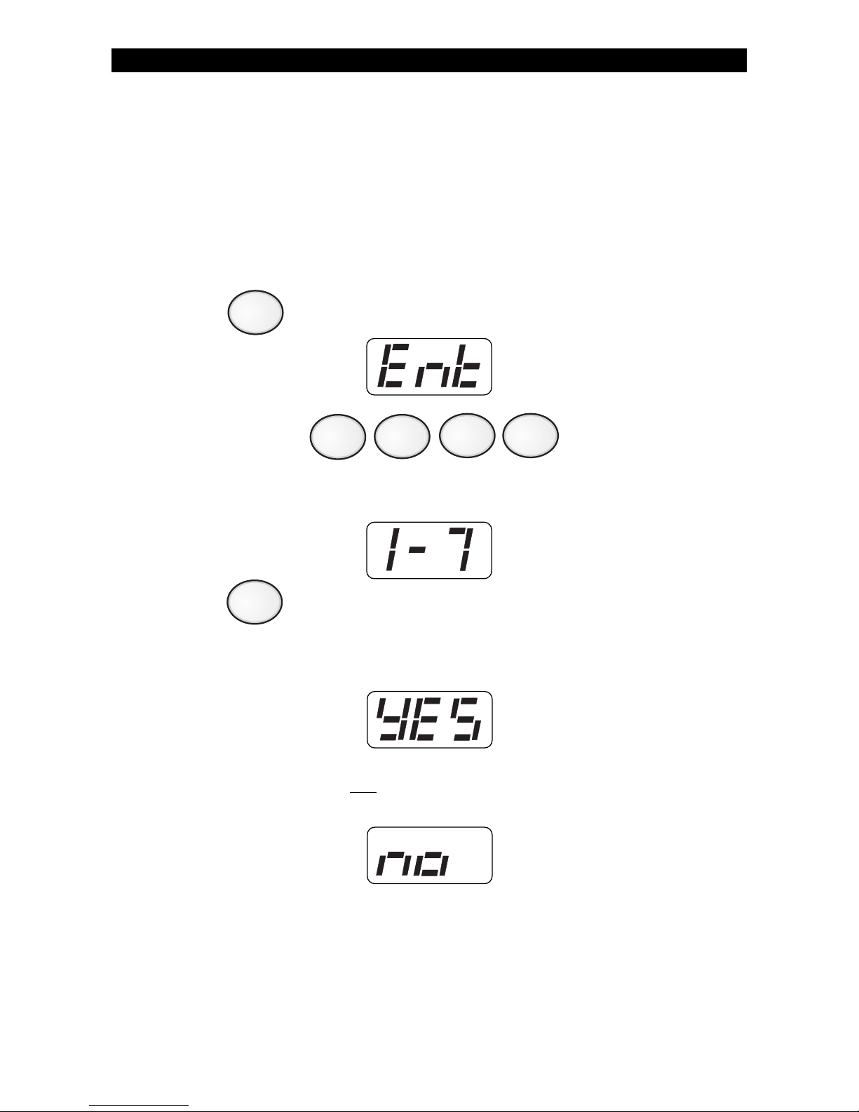
Cancelling the Automatic-ON for Today
If your system is programmed to perform an Automatic-ON scheduled
for today, you may cancel it for today only without changing your
programmed schedule.
To cancel Automatic-ON for today:
1. Press . The Control Station will display:
2. Enter passcode: .
The Control Station will display:
3. Press .
If Automatic-ON was programmed for today, the Control Station
will display:
If Automatic-ON was
not programmed for today, the Control
Station will display:
6
9
Page 46
46
Cancelling Exit-ON for Today
If your system is programmed to automatically turn ON ten (10)
minutes after you leave the premises with no other activity detected,
you may cancel it for today only.
To cancel Exit-ON for today:
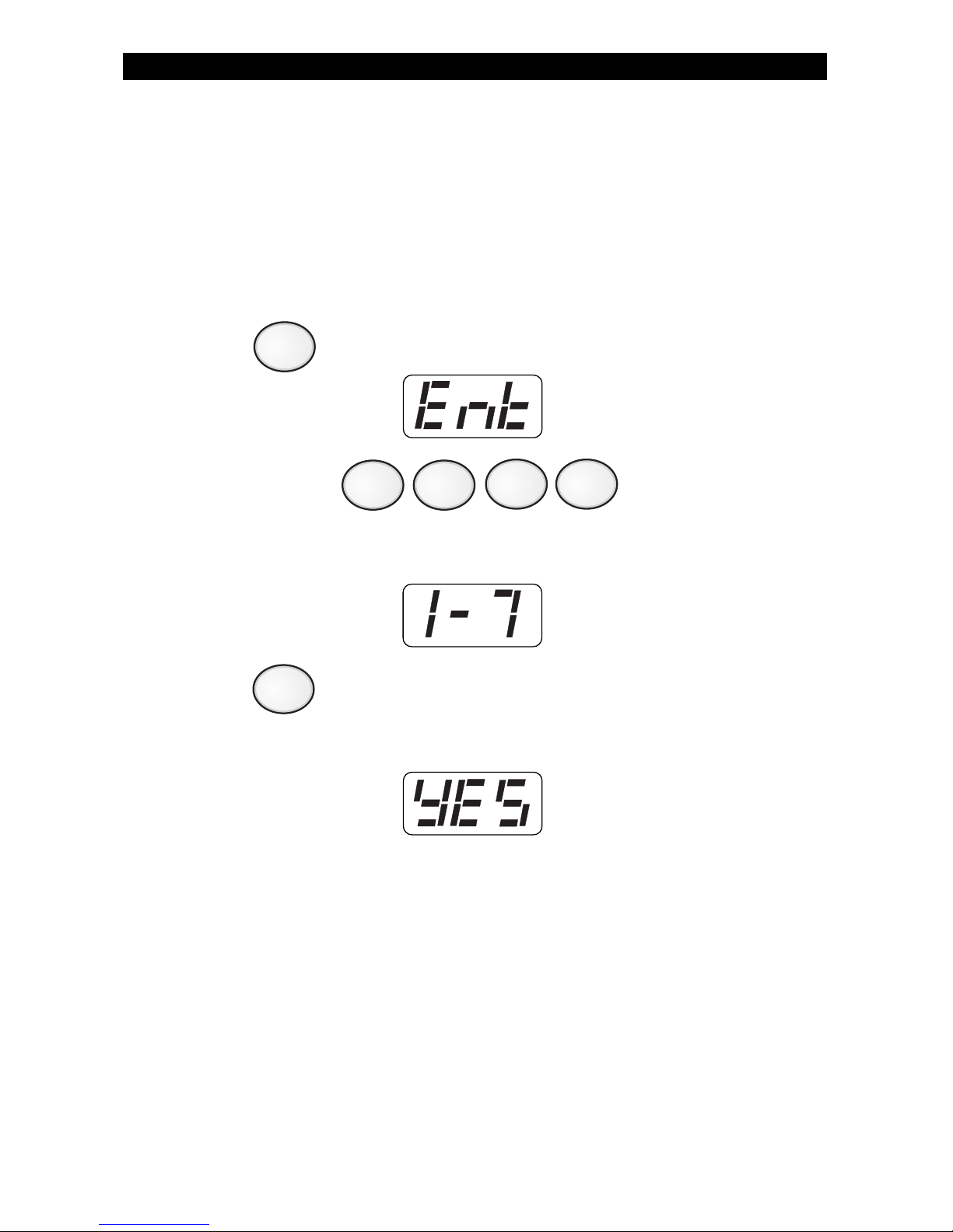
1. Press . The Control Station will display:
2. Enter passcode: .
The Control Station will display:
3. Press .
If Exit-ON was programmed for today, the Control Station will
display:
ZX400/ZX410 PROGRAMMING
9
7
Page 47
47
Multi-Area Operation
(ZX400/ZX410 only)
Your system may be configured with two separate areas of protection.
For example, a duplex may have one system but have both halves set
up as separate areas for protection. Or, you may have one system for
your house and a storage building with each building set up as separate areas for protection. See your security company representative for
more details.
If you have access to both areas through a Control Station, the Control
Station will prompt you to make an area selection for Area 1, Area 2, or
both for any operation, test, or programming that is performed. The
display will alternate between the Primary and the Secondary area
when the Secondary area is turned ON or in alarm.
EXAMPLES:
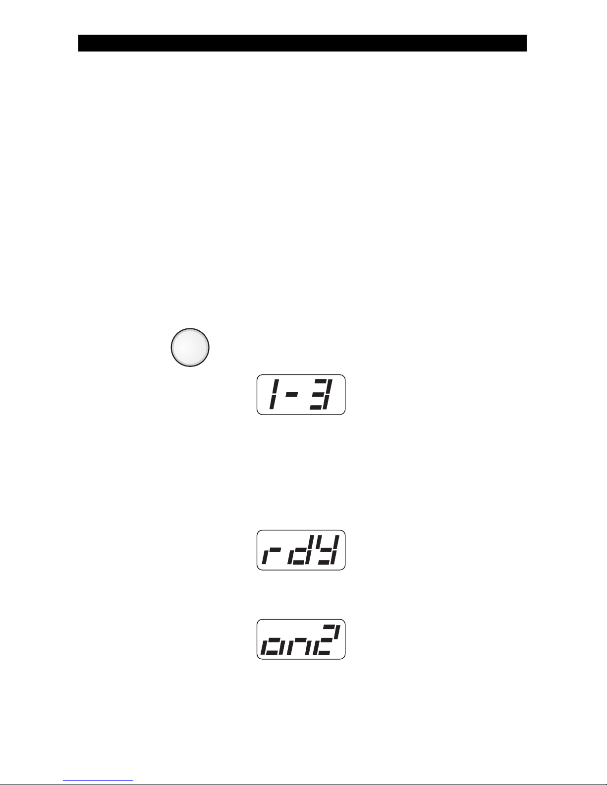
If you press then enter your passcode, the Control Station will
display:
Your options are: Press 1 for Area 1
Press 2 for Area 2
Press 3 for both
If Area 1 is turned OFF and Area 2 is turned ON, the display will
alternate between the Ready display for Area 1:
and the ON display for Area 2:
MULTI-AREA OPERATION
AWAY
Page 48

48
Introduction
Your system may include fire detection, depending on the options
purchased and the local codes and regulations for your area. Fire alarm
systems are always active and cannot be turned OFF. All fire systems
require regular testing and maintenance. Common household dust
buildup in smoke detectors can cause them to false alarm or fail in a
time of need. Consult your Security Company Representative for a
scheduled maintenance program.
All devices in a Fire Alarm system should be tested monthly except as
described in NFPA 72. See Testing Your System - Walk Test for testing
zones and Bell Test for testing the bell.
When an Alarm Occurs
When a Fire Alarm occurs, the bell sounds, the keypads produce the fire
alarm tone and display a Fire Alarm message and/or display the zone
that caused the alarm.
To silence the alarm, press the Off Cancel key and enter your passcode.
If you silence a Fire Alarm and the Control Station goes into Alarm
Memory Mode (see Alarm Conditions - Alarm Memory), the alarm will
be reported if your system is connected to a Central Station. The
Ready and Trouble LED will flash. If a false alarm occurs, notify the
authorities immediately.
If you silence a Fire Alarm and the Control Station does not go into
Alarm Memory mode, then the alarm was aborted and the Trouble LED
will be illuminated. You have 255 seconds to reset the smoke detector
(see Resetting Smoke Detectors below), otherwise the smoke detectors
will reset automatically after 255 seconds have elapsed.
Resetting Smoke Detectors
Most smoke detectors “latch” in an alarm condition once they are
triggered. If your keypad displays a trouble condition at the zone after
Fire Detection
OPTIONAL FEATURES
FIRE DETECTION
Page 49

49
you have silenced a Fire Alarm, you will need to reset the smoke
detector. Press the RESET SMOKE key (7) and enter your passcode.
The trouble condition should disappear on the zone in a couple of
seconds. If the trouble condition does not clear after resetting the
smoke detector, contact your installer for service.
You cannot reset smoke detectors while the alarm is
sounding, you must silence the alarm first.
Developing An Evacuation Plan
Preparation and education are of prime importance in the prevention of
fire. An evacuation plan should be established BEFORE a severe
situation arises. Your security system may or may not contain fire
detection and notification equipment. Make sure your Security Company Representative fully explains the configuration of your system.
Make sure you fully understand the limitations of your system.
Use the following steps in establishing an evacuation plan:
1. Evaluate all possible escape routes from your home and draw a
floor plan.
2. Select two exit escape routes from each room.
3. Provide escape ladders for rooms above the first floor. Check the
ladders to be sure that they will reach the ground.
4. Draw a rough sketch of your escape plan so that everyone is
familiar with it.
5. Practice your escape plan to assure that everybody knows what
they have to do in a severe situation.
6. Establish a meeting place outside where your family is to report.
7. Advise the local fire authority if you have installed a fire alarm
system.
Discuss the following with all residents:
1. Familiarity with alarm signals.
2. Status of bedroom doors.
3. Testing of door during a fire and use of alternate escape routes if
HOT to touch.
4. Crawling and holding breath techniques during a fire.
5. ESCAPE FAST, DO NOT STOP for packing.
6. Emphasize that no one is to return to a burning building.
FIRE DETECTION
NOTE
Page 50

50
OPTIONAL FEATURES
FIRE DETECTION
Fire Prevention And Escape
The purpose of heat and smoke detectors is to detect a fire in its earliest
stages and sound an alarm, giving you more time to exit the premises
before smoke reaches a dangerous level.
Know Fire Hazards
No detection device can protect life in all situations. Therefore, safeguards should be taken to avoid such potentially dangerous situations
as smoking in bed, leaving children home alone, and cleaning with
flammable liquids such as gasoline.
The best fire protection is minimizing fire hazards through proper
storage of materials and good housekeeping practices. Careless use of
combustible materials and electrical appliances overloading electrical
outlets are major causes of fire. Explosive and fast burning materials
must be eliminated from the home.
In Case Of Fire
Leave immediately! Do not stop to pack or search for valuables. In
heavy smoke, hold your breath and stay low - crawl if necessary. The
clearest air usually is at the floor. If you have to go through a closed
door, carefully feel the door and door knob to see if undue heat is
present. If relatively cool, brace your foot against the bottom of the
door with your hip against the middle, and one hand against the top
edge. Open slightly. If there is a rush of hot air, slam the door quickly
and latch it. Unvented fire will build up considerable pressure. Be sure
that all members of the household realize this danger.
Use your neighbor’s phone or street fire alarm box. The job of extinguishing the fire should be left to the professionals. Too many unforeseen things can occur when inexperienced people try to extinguish a
fire.
Page 51

51
Be Prepared
Perform fire drills regularly. Use them to assure recognition of an alarm
signal. For your protection, simulate different circumstances (smoke
the hall, living room, etc.). Then have everyone react to the situation.
Draw a floor plan and show two exits from each room. It is important
that children be instructed carefully. Their tendency is to hide in a
crisis.
It is imperative that one meeting place outside the home be established. You should insist that everyone meet there during an alarm.
This will eliminate the tragedy of someone reentering the house for a
missing member who is actually safe.
If you have small children and/or invalids residing in your household,
you can help your fire department by placing decals on bedroom
windows. Most fire departments supply the decals.
Become familiar with the distinctive sounds of your Fire alarm and
Burglar alarm signals.
Fire Supervisory (ZX400/ZX410 only) & Fire Trouble
If a trouble condition for a Fire zone is displayed on your keypad,
consult your installer. A Fire Trouble condition results when a fire alarm
is silenced and when the smoke detector has not been reset, or when
the smoke detector is dirty and needs to be cleaned/serviced. A Fire
Trouble also results when a Fire zone is bypassed.
If none of the above apply, the Fire Trouble may be due to a wiring
problem or a supervisory condition and a service call may be required.
FIRE DETECTION
Page 52
52
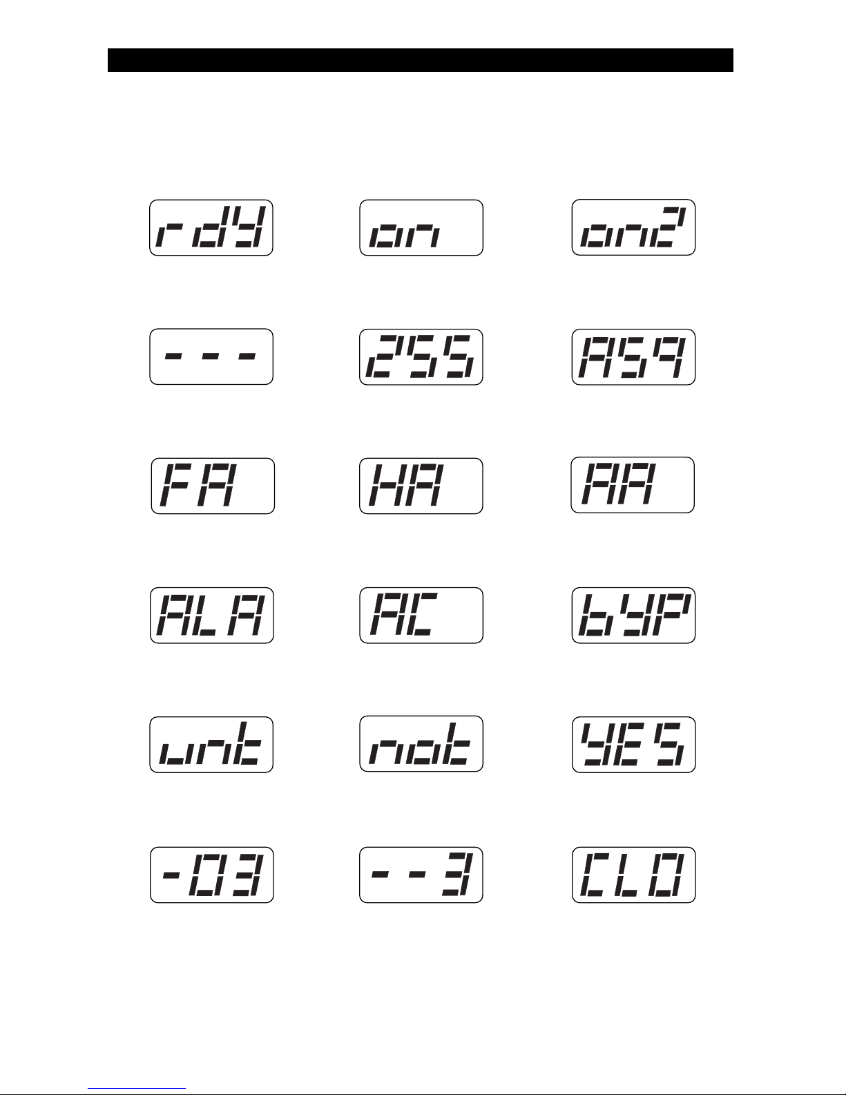
SSD Control Station Displays & Descriptions
Zones Faulted
Exit Time, Entry
Time, or Pre-Alarm
Time Countdown
Automatic-ON or
Exit-ON Warning
Countdown
Medical Alarm
Burglar Alarm Zone(s) Bypassed
Closing Report
Received
AC Power Failure
Fire Alarm Holdup Alarm
System ON
(Single Area)
System ON in Area #
(for Multi-Area)
Ready Mode
Communication Test
Passed
Condition on Zone ## Alarm from Auxiliary
Key on Control
Station #
Zone Untested
System Not Ready
OPTIONAL FEATURES
DISPLAYS AND DESCRIPTIONS
Page 53

53
Low Battery
Memory Error
Communication
Failure
Control Station
Missing
RF Jamming
Bell Line Fault
Telco Line Fault
Call RPM Failed
Zone Trouble
Fire Trouble
Fire Alarm Bell
Silenced
Fire Supervisory
Burglar Tamper
Alarm Silenced
Zone Not Responding
RF Point Supervisory
Smoke Detector
Maintenance
Needed
RF Point Tampered
RF Point Low Battery
Error Code Displays
No Communication
From Control
ERROR CODE DISPLAYS
Page 54

54
Glossary
Alarm Memory: A history of the alarms that occurred most recently.
Bypass: To temporarily remove a zone from operation.
Control Station: The remote station used to enter instructions to the
control panel such as to arm, disarm and bypass. Also called a keypad.
Entry Time: Time permitted to enter the armed premises through a
delay defined zone.
Faulted: A detection zone which is not secure, such as a protected
door or window which has been left open causing the control to lose
its “Ready” status.
Force Arm: To override. To force the system to arm when one or more
zones are not ready.
Indicator Lights: The lights (LEDs) on the Control Station.
Interior: The backup or second line of defense. Consists of one or
more zones that detect intruders that have already entered the building. Interior detection devices usually consist of motion detection
devices, interior door contacts, and under carpet sensors designed to
surprise the intruder.
Keypad: A generic term for the Control Station.
Latch Key Supervision: Monitors the entry of a passcode according to
a schedule.
Program: To set the operating characteristics of the main system
electronics such as the passcode which is used to arm and disarm.
Ready: The system is ready to be armed.
Remote Programming: The ability to service the system from a
remote location (specified by our Security Company Representative)
with the aid of a computer.
Sensors: Devices that detect violations and report such conditions to
the control panel. Sensors include door and window contacts or any
device used to inform the control of a particular condition.
OPTIONAL FEATURES
GLOSSARY
Page 55

55
Supervisory/Trouble: Your installer may have defined one or more of
your control’s zones for supervisory/trouble condition indication. (All
Fire zones are automatically supervisory/trouble zones). If a wire breaks
on supervisory/trouble Fire zone, the Control Station sounder will beep
continuously to alert you of the problem.
User Passcode: A code which is used to perform operations on the
system
Zone: The areas of protection represented by zone indicators.
GLOSSARY
Page 56

56
OPTIONAL FEATURES
INDEX
A
Access Key 6
Access Output 6, 19, 20
Alarm Memory 10, 22, 48, 54
Alarm Memory Key 6
Armed Status Indicator 7, 10
Authority Level 30, 43
Automatic-ON 6, 17, 18, 32,
34, 45, 52, 59
AWAY 7, 9, 11, 17, 18, 28,
34, 58
B
Battery Test 24, 25
Bell Test 24, 26, 48
Bypass 11, 13, 14, 15, 23
51, 52, 54, 59
Bypass Key 6
C
Chime 12, 38
Chime Key 6
Clock 32, 33
Communicator Test 24, 27
D
Delay Arm Key 6
Duress 19
E
Event Log 12
Event Log Key 6
Exit-ON 17, 32, 46, 52, 59
F
Fire 2, 7, 20, 48-51, 53, 55
58, 59, 60, 61
Fire Alarm 2, 48-51, 52, 53
Fire Trouble 51, 53
Force-Arming 16, 59
I
Instant Key 6
K
Keypad Test 28
Keyswitch 18, 59
L
Lamp Trigger 21
Latch Key 32, 38, 39, 40, 54
M
Multi-Area Operation 47
N
NFPA 48
NIGHT 6, 7, 9, 11, 17, 28,
34, 58
O
OFF 6, 8, 10, 11, 12, 13, 18,
21, 23, 24, 47, 48, 63
Off Cancel Key 6, 20, 48
ON 6, 7, 8, 9, 11, 12, 13,
16, 17, 18, 21, 23, 32, 34, 35,
36, 37, 46, 47, 52, 59, 63
P
Panic Key 7, 20, 58
Program Key 6
Programming 6, 17, 47, 54
ZX200/ZX210 30-31
ZX400/ZX410 32-46
Q
Quit Key 6
Index
Page 57

57
INDEX
R
Ready Light 8
Remote Connect 30, 32
Reset Smoke Key 6, 49
RF Signal Strength 24, 29
S
Secondary Function Keys 21
Security Level 11, 34
Seven Segment Display 8
Silence 6, 10, 18, 20, 23,
48, 49, 51, 53
Smoke Detectors 2, 6, 48,
49, 50
STAY 6, 7, 9, 11, 17, 28,
34, 58
System Not Ready 8, 9, 11,
16, 52
T
Test Key 6
Trouble Condition 23, 25, 27,
48, 49, 51, 55
Trouble Light 8, 23
Trouble Zones 23, 55
U
Unbypass 14, 15
Universal Output 21
User ID Passcode 31, 43, 44
User On Premise 20, 59
V
View Info Key 6, 11, 22, 23
W
Walk Test 24, 48
Z
Zone Conditions 23
Zone Trouble 8, 53
Page 58

58
OPTIONAL FEATURES
SYSTEM REFERENCE GUIDE
12 3
45 6
Emergency Numbers
Police Fire
Neighbor Doctor
Central Station Service Rep.
Central Station Subscriber Number
Delay Times
Seconds of exit delay time for AWAY arms
Seconds of exit delay time for STAY and NIGHT arms
Seconds of entry time (Delay 1) for Zone(s)
Seconds of entry time (Delay 2) for Zone(s)
Seconds of pre-alarm time
Control Station Location
Circle the Control Stations that have the Panic Keys Enabled
Panic Key (Key ”A”) Enabled 123456
Sound
Panic Key (Key “B”) Enabled 123456
Sound
Panic Key (Key “C”) Enabled 123456
Sound
System Reference Guide
Page 59
59
SYSTEM REFERENCE GUIDE
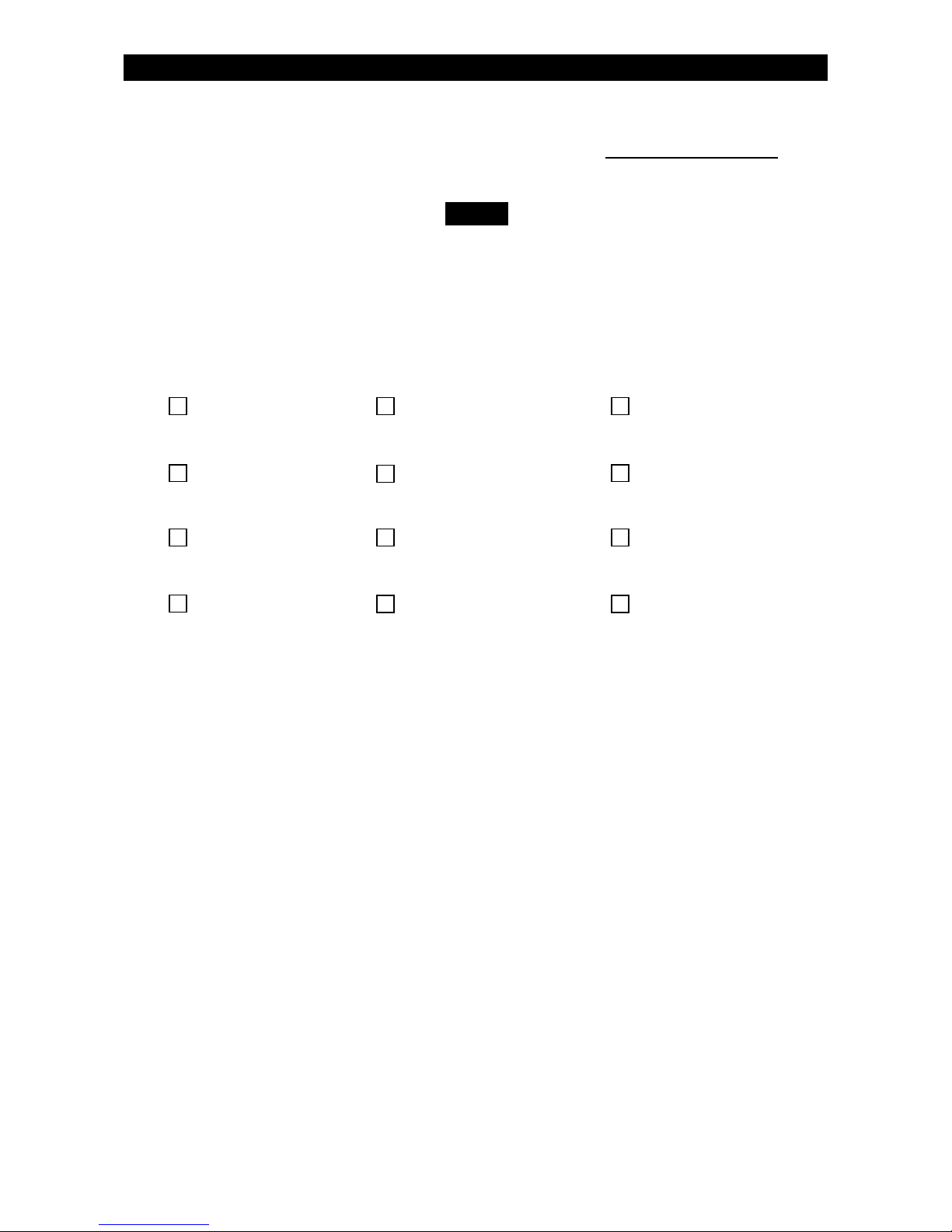
Bypassing Exit-ON Hold Up
Force-Arming Automatic-ON Auxiliary Alarm
Double Press ON Keyswitch User On Premise
Two Button ON Household Fire Intrusion
Features Enabled
The lockout is a temporary measure that affects only
the Control Station in use for the passcode attempts.
NOTE
Passcode Attempts Before Control Station Lockout:
Page 60

60
Protection Zones
One or more sensing devices have been assigned by the installer of
your alarm system to each of the various protection zones in your
system (although not every zone may have been used). For example,
the sensing device on your Entry/Exit door may have been assigned to
zone 01, sensing devices on windows in the master bedroom to zone
02, and so on. For your convenience, a chart has been provided below
which may be used to record the specific protection points that have
been assigned to each zone in your system. Your installer will assist you
in recording this information. Only zones 1-8 are available with the
ZX200/ZX210.
Zone Protection Point(s) Zone Protection Point(s)
01 16
02 17
03 18
04 19
05 20
06 21
07 22
08 23
09 24
10 25
11 26
12 27
13 28
14 29
15 FIRE
OPTIONAL FEATURES
PROTECTION ZONES
Page 61

61
Owner’s Insurance Premium Credit Requested
This form should be completed and forwarded to your homeowner’s insurance
carrier for possible premium credit.
This control is UL Listed for: UL Grade A Household Burglary
UL Household Fire
A. General Information:
Insured’s Name and Address
Insurance Co.
Policy No:
Moose Security System
Type of Alarm: Burglary Fire Both
Installed by:
Serviced by:
B. Notifies (Insert B=Burglary, F=Fire)
Local Sounding Device: Police Dept. Fire Dept.:
Central Station: Name and Address:
C. Powered By: A.C. With Rechargeable Power Supply
D. Testing Quarterly Monthly Weekly Other
(Continued on Reverse)
Page 62
62
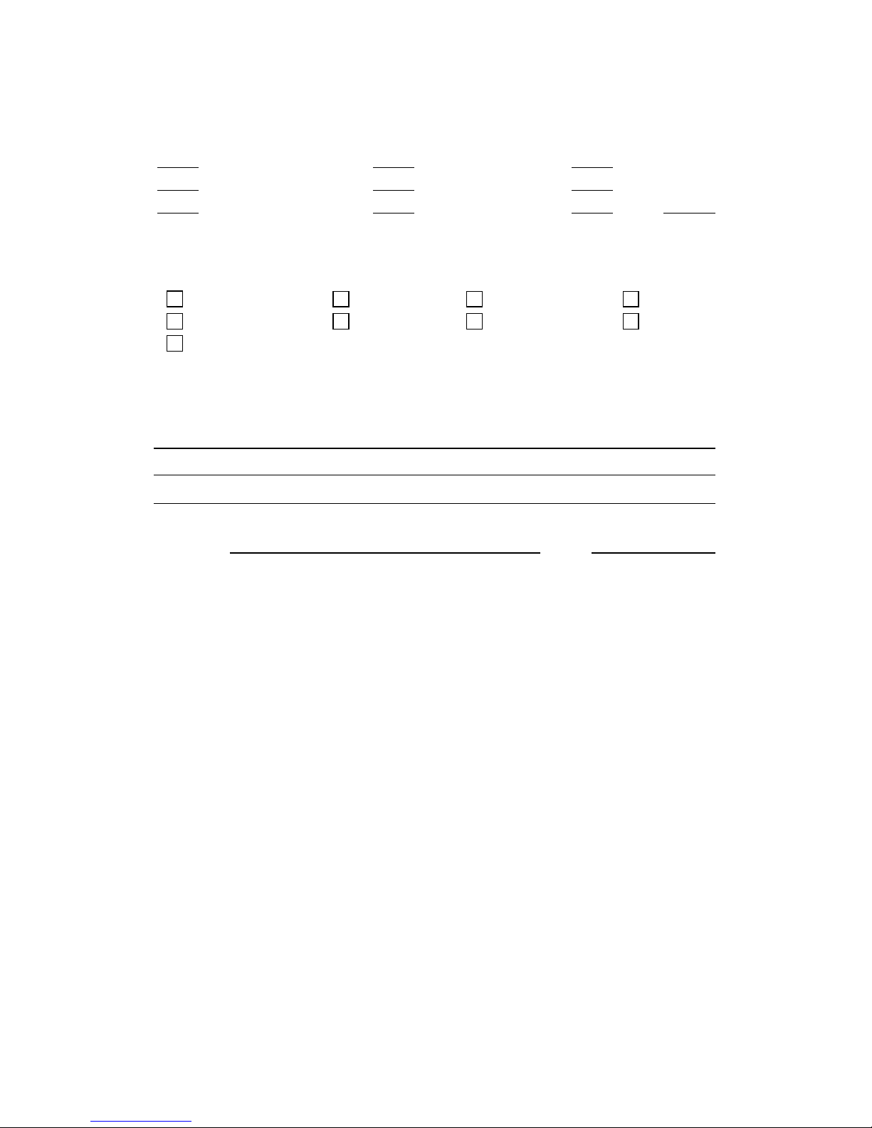
E. Smoke Detector Locations
Furnace Room Kitchen Bedrooms
Attic Basement Living Room
Dining Room Hall Other
F. Burglary Detecting Device Locations:
Front Door Basement door All Exterior Doors Rear Door
1st Floor windows All Windows Interior Locations Other
All Accessible Openings, Including Skylights, Air Conditioners and Vents
G. Additional Pertinent Information:
Signature: Date:
Page 63

63
FCC Compliance
FCC COMPLIANCE
Part 68 Notification
This equipment complies with Part 68 of the Federal Communications Commissions (FCC) rules. All connections to the
telephone net work must be made through standard telephone company plugs and jacks, RJ31-X or equivalent, in such a
manner as to allow for easy and immediate disconnection of the equipment. If the connection cord is unplugged from the
jack, there shall be no interference to the telephone equipment still connected to the telephone network.
The FCC registration number and Ringer Equivalence Number (REN) can be found printed on the wiring connection label
located inside the Control Box Enclosure. If requested, provide this information to your telephone company. The REN is
useful to determine the quantity of devices that may be connected to your telephone line and still have all of this devices ring
when your number is called. In most, but no all, areas, the sum of the RENs of all devices should not exceed five.
In the unlikely event that the equipment should ever fail to operate properly, it should be disconnected from the telephone
jack to determine if the problem is with the telephone net work or with the equipment. If a problem is found with the
equipment, leave it disconnected until it is repaired or replaced.
In the unlikely event that the equipment should ever cause harm to the telephone network, the telephone company may
temporarily discontinue your service. If possible, they will notify you in advance. However, if advance notice isn’t practical,
the telephone company may temporarily discontinue service without prior notification. In the case of temporary
discontinuance, the telephone company shall promptly notify the telephone subscriber who will be given the opportunity to
correct the situation. The customer also has the right to bring a complaint to the FCC if he feels the disconnection is not
warranted.
Your telephone company may make changes in its facilities, equipment, operations, or procedures that could affect the
proper operation of your equipment. If they do, you will be given advance notice so as to give you an opportunity to
maintain uninterrupted service.
You should notify the telephone company if this equipment is removed from the premises and the telephone jack is no longer
needed.
The FCC prohibits the connection of this equipment to party lines and the use of this equipment in conjunction with coinoperated telephone service. An AC surge arrestor should be installed in the system’s AC power outlet.
Part 15 Notification
This equipment has been tested and found to comply with the limits for a Class B digital device, pursuant to Part 15 of FCC
rules. These limits are designed to provide reasonable protection against harmful interference when the equipment is
operated in a residential environment. This equipment generates, uses, and can radiate radio frequency energy and, if not
installed and used in accordance with the instruction manual, may cause harmful interference to radio communications.
However, there is no guarantee that interference will not occur in a particular installation. If this equipment does cause
harmful interference to radio or television reception, which can be determined by turning the equipment OFF and ON, the
user is encouraged to try to correct the interference by one or more of the following measures:
• Reorient or relocate the receiving antenna.
• Increase the separation between the equipment and the receiver.
• Connect the equipment into an outlet on a circuit different from that to which the receiver is connected.
• Consult the dealer or and experienced radio/TV technician for help.
CAUTION: Changes or modifications not expressly approved by the manufacturer could void the user’s authority to
operate the equipment.
Canadian Notice
The Canadian Department of Communications label identifies certified equipment. This certification means that the equipment
meets certain telecommunications network protective, operational and safety requirements. The Department does not guarantee
that the equipment will operate to the user’s satisfaction. Before installing this equipment, users should ensure that it is
permissible to be connected to the facilities of the local telecommunications company. The equipment must also be installed
using an acceptable method of connection. In some cases, the company’s inside wiring associated with a single line individual
service may be extended by means of a certified connector assembly (telephone extension cord). The customer should be aware
that compliance with the above conditions may not prevent degradation of service in some situations. Repairs to certified
equipment should be made by and authorized Canadian maintenance facility designed by the supplier. Any repairs of alterations
make by the user to this equipment, or equipment malfunctions, may give the telecommunications company cause to request the
user to disconnect the equipment. Users should ensure for their own protection that the electrical ground connections of the
power utility, telephone lines and internal metallic water pipe system, if present, are connected together. This precaution may be
particularly important in rural areas.
CAUTION: Users should not attempt to make such connections themselves, but should contact the appropriate electric
inspection authority, or electrician, as appropriate.
The
LOAD NUMBER (LN) assigned to each terminal device denotes the percentage of the total load to be connected to a
telephone loop which is used by the device, to prevent overloading. The termination on a loop may consist of any combination
of devices subject only to the requirement that the total of the Load Numbers of all of the devices does not exceed 100.
This equipment is a Class B Digital apparatus which complies with the radio interference regulations, CRC c. 1374.
All Rights Reserved
No part of this publication may be reproduced, stored in a retrieval system, or transmitted in any form, or by any means electronic, mechanical, photocopying, recording, or otherwise without the prior written permission of the manufacturer. The
material in this publication is for information purposes and subject to change without notice. The manufacturer assumes no
responsibility for any errors which may appear in this publication. Printed in U.S.A.
Page 64

64
MOOSE
a product of sentrol, inc
Sentrol, Inc. reserves the right
to change specifications
without notice.
©
1997 Sentrol, Inc.
64812800B
 Loading...