

lnstallation
lnstructions
"'MOOSEMPI-712a
S eU-CoiI ai ned
C o n tro I S t a t io n
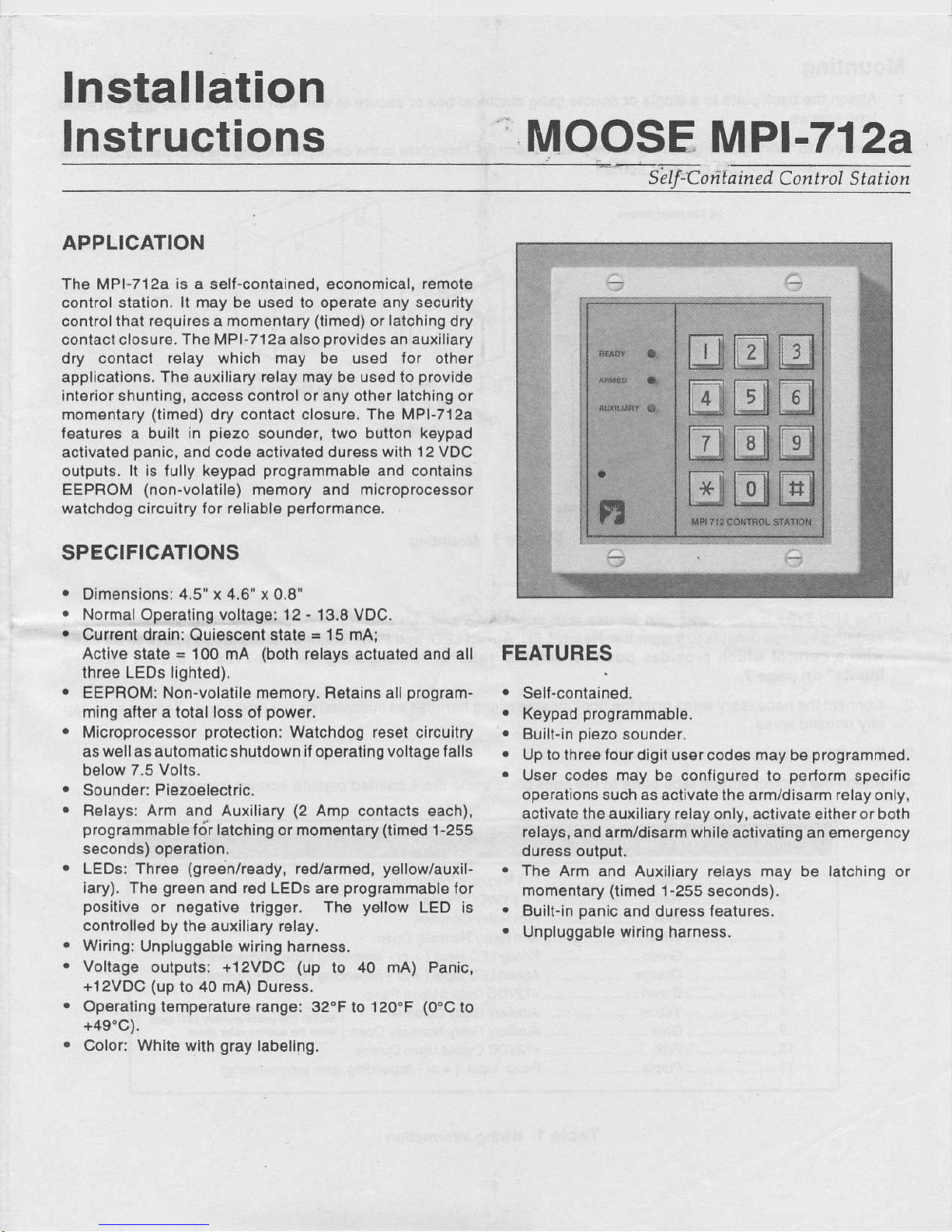
APPLICATION
The MPF712a
is a selFqontain6d,
economical,
remole
control slalion. lt may be used to operate any security
controlthal requires a momentary
(timed)
or
latching
dry
conlact closure.
The
MPI-712a also
provides
an auxiliary
dry contact relay which may be used lor other
applications. The auxiliary relay may be used lo
provide
interior shunting, access control or any olher latching or
momentary
(timed)
dry contact closure. The MPI-712a
features
a buill
in
piezo
sounder,
two bulton keypad
actlvated
panic,
and code activated duress
with 12 VDC
outputs, lt ls fully keypad
programmable
and conlalns
EEPROM
(non-volatile)
memory and mlcroprocessor
',vatchdog
circuitry f or aeliable
poatormance.
SPECIFICATIONS
Oim€nsionsi 4.5" x 4,6" x 0.8'
Normal Operating voltage: 12
.
'13,8
VDC.
Current draln:
Ouiesc€nl
slat6 : 15 rnA:
Actlve stste
=
'100
mA
(both
r€lays actuat€d and all
thr6e LEDs lighted).
EEPROM: Non-volatile memory, Botains all
program-
mlng att€r a total loss ol
power,
Mlcroprocessor
protectlon:
Watchdog res€t clrcultry
a6
wellas aulomatic
shuldown
itopgrating voltage falls
below 7.5 Volls.
Sounder: PlEzoeleclrlc.
Relays: Arm an_d Auxiliary
(2
Amp contact6 each),
programmable
lor lalching or mom€niary
(tim6d
1
-255
s6conds) op€rallon.
LEDs:
Thr€e
(gre.jn/roady,
redlarmed,
yellow/auxil-
iary). The
green
and
r6d LEDS ar6
prcgrammable
lor
positive
or negative trigger. The
yellow
LED
is
controlled by the auxiliary
relay.
Wiring:
Unpluggable wiring
harnes6.
Voltage
oulputs: +12VDC
(up
to 40
lnA)
Panic,
+l2VDC
(up
to 40 mA) Duress.
Operating temperature range: 32"F
to 120.F
(0.C
to
+49"C).
Color: Whit€ with
gray
labeling.
FEATURES
.
Sell-contained.
.
Keypad
programmable.
.
Built-in
piezo
sound€r,
.
Up lo thr€e lour digit usor
codes
may
be
programmed.
.
User codes may be configured to
perlorm
specilic
op6rations such
as actlvate the arm/disarm relay only,
activate the auxiliary relay only, activate eitheror both
relays, and ar[Vdisarmwhile
activating
an emergency
dur6sa outout.
.
Tho
Arm and Auxiliary relays may be latching or
momentary
(timed
l
-255
seconds).
.
Buill-in
panic
and
duress
featurcs.
.
Unpluggable wiring
harness.
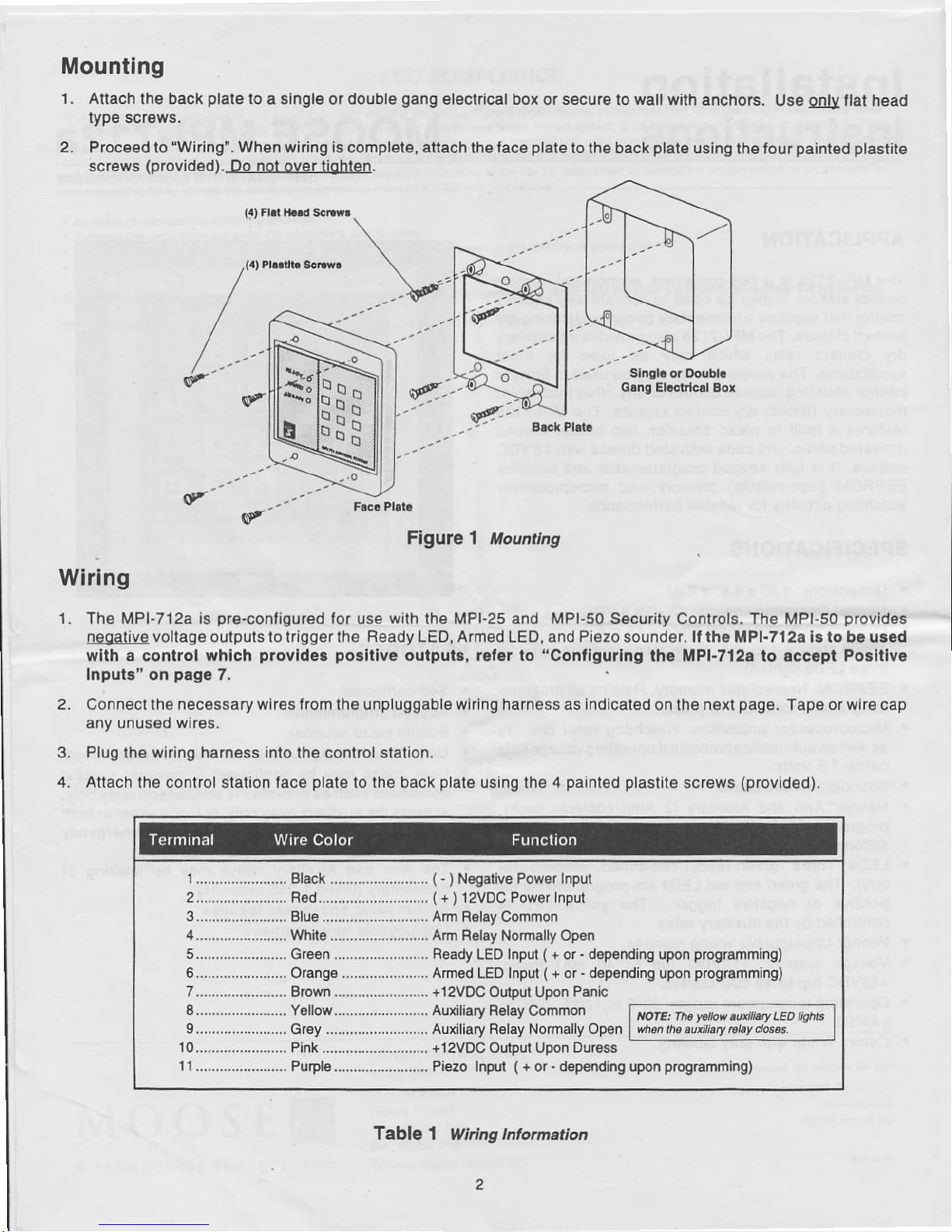
Mounting
1. Atlach lho back
plate
lo
a singlg or double
gang
electrical box o. secu.e to wall
with anqhors.
Use
Odly
llat head
type scr€ws.
2.
Proc€ed to
"Wrlng".
When widng 19
complete,
attach
the
lac€
plate
lo lh9 back
plate
using the four
paintsd plastit€
screws
(providod).-Qg_n0byettigllen.
Glng
El.crrlcll
gox
'-
F.c. Plai.
Flgule 1 Mounttng
Wirlng
'1.
The MPI-712a is
pr€.conligured
for use with th€ MPI-25 and MPI-50 Secu.ity Controls. Tho MPI-50
provldos
leggliyg
voltage
outputs to trigger lhs R€ady LED, Armsd LED, and Pi€zo sound€r. lf th. MPl.7l2a ls lo b. u..d
wlth a control whlch
provldsa pollllve
oulput.,
rolor to
"Contlgurlng
lho MPI-712a to rccrpt Polltlv.
Input." on
pag.
7.
2. Connect lh€ necossary wires trom
the unpluggable wiring harness as
indicated
on the n€xt
page.
Tape or
wire
cap
any unuseo wres.
Plug
tho wiring harn€ss into the conlrol stalion.
Attach
the control station face
plate
to the back
plate
using the 4
painted plasilt€
screws
(provid€d).
1
....................... Bleck .........................
(
-
)
N€gatlvg Pow€r Input
2.........,,.,..-.......
Fed..........,.,,.........,.,.,
(
+
)
l2VDC Pow€r
Input
3...-..........-........
Blue ........................... Arm R€ley Common
4.......................
Whit€......................... furh Relay Normally Opsn
5....................... Green ........................ Ready
LEO
Input ( +
or
-
dsp€nding
upon
progranming)
6.......................
Orangg
...................... tumed
LEO Input ( +
or - depending
upon
prog.anming)
7..,....................
8rown.........
.............. +1zVOC
Outsut Upon
Panlc
8...............-....... Ye1|ow........................ Auxiliary
R6lay Common
9........-.-....-..-
Gr€y
.....,.,,...............,.
Auxiliary R6lay Norhally Opon
10.......................
Pink ................-........,. +12VDC OutDul UDon
Dur€ss
ttOIE: flb
yo
ow.utlLty LEo n$ns
when
lha autiltiary d4
da6.
11....................... Purpl€........................
Piezo InM
(
+
or. depeoding upon
p.ogramming)
Table
1 Wirlng
lnlormation
2
MPI-50
Security
Control
NOTE:
This erampto
illuBi.at€s
hookup to a MPI-50
Securlty
control
whlch
provldo3
negative
oulputtrlggare.
Many controls
provi{le
Posltlv6
outputs
io
which caEs it wlllbo necossary
to change tho
MPI-712a
inFuI
polafity,
See
"Conrlguring
th€
MPI-712a io accepl Posltlve
Inpufs
'on
prgo
7.
Auxiliary F.lry
Outpor
1y
iE
"9
g
3: :t I
456
l
I
910
I
E
NOTE: Blu€ .nd
white leads clorg
XOTE:
Ths Ar
upon €ntry ot afm/
Oisaam cod€.
+l2VOc ouQur
Figufe 2 MPI-50 Contol Pancl Hookup
more 19cenl
for loua.tunctlor
appllcallons,
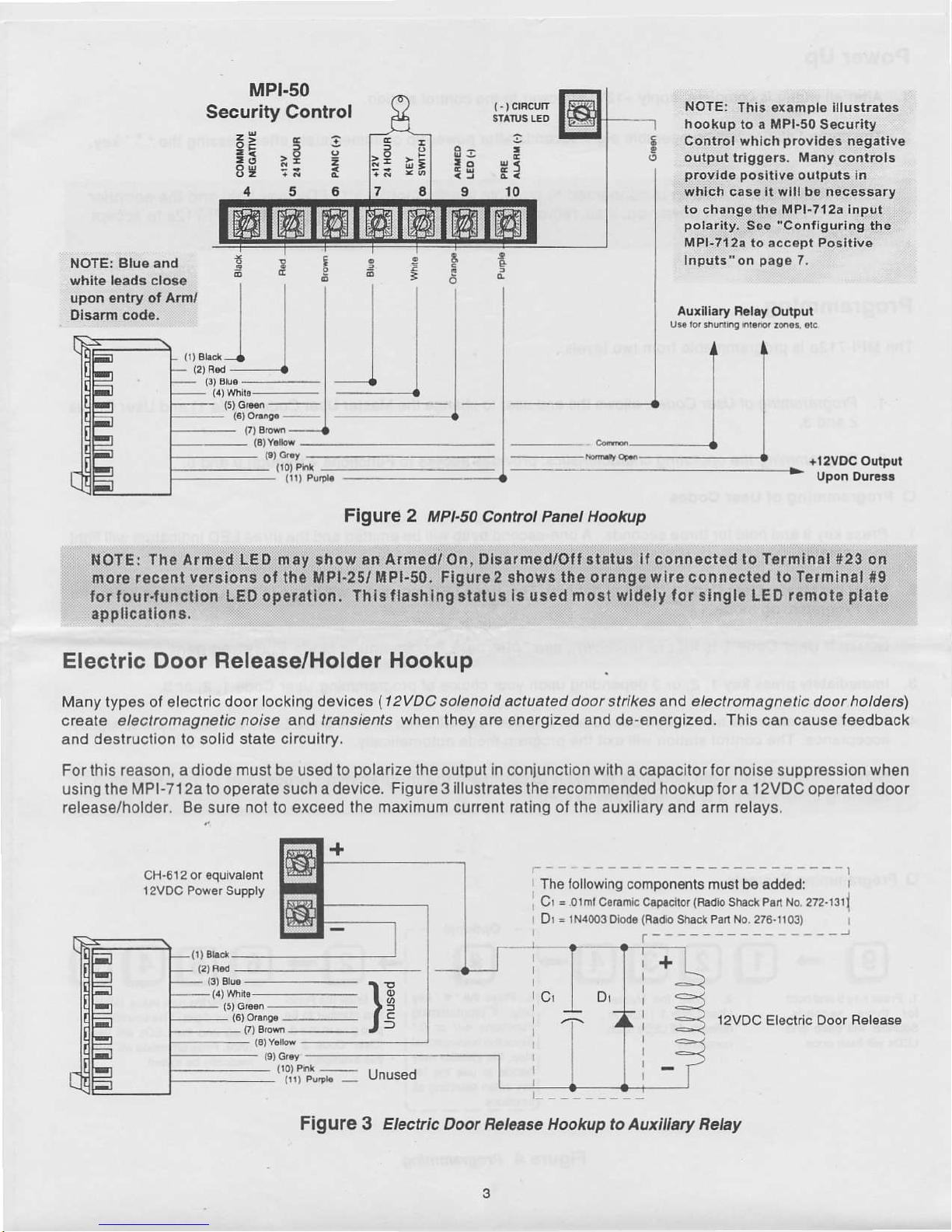
Electric Door Release/Holder
Hookup
Many types ot electrio door
locking devices ( t ?VDC solenoid actuated doot sl kes and electrcmagnelic door holde6\
cteale elect@magnetic
noise and tansienls
when
they ar€ energized and d€-energiz€d. This can cause leedback
and
destruction io solid state circuatry.
Forthis reason, adiode mustbe used lo
polarize
lhe oulput in
conjunction
wilh
a capacitorlor noise suppression when
using the MPI-712a to operate such a device.
Figure 3 illustrates
the
recommended
hookup lor a 12VDC operated door
release/hold6r. 8e sure
not
to exce€d the
rnaximum currenl ralino
ol
the auxiliary
and arm relays.
The tollowing cofiponents musl bs add€d:
C = O
nr
Co6m'c C.p!dto.
{R.d'o
Srac\
Psd
No 2?2
tlt
l
Dr
-
1NaOO3
Diod.(R.dio SlEcrPanNo.276.fi03)
+
15)
G|H
{6)
o'r^s€ --
}E
12VDC
Eiect c Ooor
R€l€ase
Figule 3
Etectic
Doot Retease Hookup to Auxitlary nehy

Power Up
1. Alter
all wiring is complete,
apply +12VDC
power
to the control
statioh.
2. The control station
will
be operable eight
seconds after
poweFup
or imm6diately alter
pressing
lhe "
*
"
key.
Programming
The MPI-712a
is
programmable
lrom two levels.
1. Progrcmning
ol User Codes; allows the
end user to
change
lhe Master User Code
(Code
1)
and
User Codes
2 and 3.
tr
1.
3.
2. Progtamming the operating
charucteistics.
provid€s
access to
Functions 4
through I and 0.
Programming ol UaeJ
cod63
Press k€y I and hold lorlhr€e
soconds. A on€-second b€ep
will be
€mitted and the three LED
indicators will lighl
momentarily.
2. Enterthe
Master User Code 1
(1234
al default), Th€ three LED indlcalors will begin lo
llash,
signilying
entry into
the Programming
mode.
lmmedial€ly
pr€ss
key 1, 2, or 3
dopending upon
your
choice ol
prograhmlng
Us€r Code 1, 2,
or 3.
lmmediately enler the new 4 dlgil
user Code. The sound€r will beep and the three
LEDs
will
llash once to signity
acceptance. The control staiion
will exil lhe
program
mode automatically.
O Proglamming Example
a-
Oplional
--\
g
"+
ffimmR{
l'.'ffi"'RBRH
1. PressKey 9 and hold
lor th,ee seconds.
Sounder will b€6p and
Us€r Cod6 1
(1234
at
13.
Press tre'#'key
tonly
il
p.oghmming
rFunclions
4-9 or 0'
I
sincethislsanoptional
lsiep,
the insla!lar
may
,decid6
ro lse rhe
"*"
lkey
when selecling all
5. Enl€rth€nowvalue
(MUST
b€
low
digils).The
sound€rwill
b6€p
and
the
LEDS will tlash
once.
Program mode wi I aulo-
g!99"I:---J
FigUIe 4 Prcgtamming
4

O Programming the
Operatlng Characteristics
1. Press key
9 and hold for three seconds.'
momentarily.
2. Enler the
Master user code 1
(1234
at default). The
ttuee LEDS wi
begin to flash,
signilying
entry into
the
Programming
mode.
3. Press the " # " key
to enable
programming
ol functions
4 through I or
0.
4. Selsct th6 desired Function
to be
programmed
lrom
Table 2 below.
5. Enter the
Function
number lo be
programmed..
6. Enter lhe new value for
the Function being
programm€d.
Thls value MUST
be lour digits.
The sounder
will beep
and the three
LEDS will llash once to signily
acceplance. The control
station will
exit the
program
mod6
aulomatically.
A one second
beep will be emitted
and the
three LED indicators
will
lioht
t
2
3
User Codo 1
Us6r Code 2
Us6r Code 3
Conliguralion
Digil
lor
Us€r Cod6 I
ConJiguralion Digit
lor User Cod€
2
Contiguralion Digit
lor User Cod6 3
Trigger
Poladly
Mabl€r L,ser Code
AddilionalUser
Cod6
AddilionalUser
Cod€
Assigns lh6 lunctionalily
ot User
Code 1
(see
Table 3)
Assigns
lh€ lunclionalily
ot User Codo 2
(see
Tabl€ 3)
Assagns
lhe f unclionalily
ol Us6f
Code
3
(s€e
Table 3)
T
gger
polarily I (+)
or
(
-)
I
ol
sounder and R€ady/Amed
LEDS.
Time
in seconds lhat Arm
r€lay closes when
activated.
Time
in seconds lhal Auxiliary
16lay closes when
aclivaled,
1234
0000 - 9s99
8 Arm Relay Tims
I Auxiliary Relay Time
0 Beslore Defaulls
0000
(disahl€d)
0000
-
9999
0000
(disabl€d)
0000 - 99Sg
0001
(assignedlo
0000 - 0004
aclaval€ arm
relay only)
0000ldisabled)
0000 - 0004
0000
(disabled)
0000 - 0004
0000
(negaliv€)
0000 - 0001
(0001
= positive)
0005
(5
seconds) 0000 - 0255
(s€c-)
0000 = Latching
0005
{5
seconds) 0000 - 0255
(sec.)
0000 = Latching
Enler a value of 0000lo reslorc
lactory delault valu6s to Functions
0 - 9.
f able 2 Prcgnmming
Functions

Configuration
Digits
Each User Code
(l
-
3) must be assigned
a Configuration
Digil
to define the
ope.ation(s) that
the
code is authoriz€d
lo
perform.
Selecl the desired
Configuration Digit lor
each
code trom Table
3 and
progfam
as describsd
under
'Prog16mlning
the Operating
Characteristics.'
0000 Disabl€s
Code
0001
Code aclivates
Am r€lay
only
0002
Code aclivates Auxiliary
relay
only.
0003
Code activates Arm
relay. ' #
'followed
by
code ac.tivates
Auxiliary
relay.
0004
Code activates A.m relay
and Dur€ss
trigg€ronly.
fable
3 Conflgunt on
Dtgt&
Alternate
Programming
Mode Entry
ll lh€ Master
User Code
(usorcode
I
)
ls losl or unknown,
use th€ tollowing
p.ocedure
lo ent€rthe
Programming
Mode.
1.
R€move
power
to the control station.
(Unplugging
ihe wlrlng ha.n€ss
wlll remove
power).
2 Restore
power
to lhe
conlrol slatlon.
3 Pr€ss
lhe ' # ' key withln
I seconds aller
applying
power.
The Sound€r
wlll beep onc€
and the LEos will
flash
con6tanlly
to indicate
entry Into th6
programming
mod9.
4.
Follow
the
progJamming
steps on
pag€
4
or 5 as required.
Restoring
Factory
Defaults
Follow
lh€
steps
below
to restore the
laclory default
valu€s to
Functions O - 9:
1. Enter
lhe
programming
mod€ as described
earlier.
2.
Press
the " #' key
to enable
prognmming
of Functions
4 through
9 or 0.
3. Press'0'to
select
Function 0
("Restore
Defautts").
4. Ent6r
0OOO. The
sounder wi
beep and the LEDS
wi
ash once to signity
accepranc€.
5.
Pleas6 noto
that all
custom
programming
is now
eras€d and
the factory defaults
values ar6
r€stored, inctuding
the
programming
for
the input
polarity
of the LEDS
and th€
piezo
soundgr.

Conliguring the MPI-712a
to accept Positive
Inputs
The MPI-712a is
pre-conllgured
to accept negative
trigger inputs forlhe Ready
and Armed
LEDs and the
piezo
sounder.
Many
security conkols arq
supplisd
with
positive
outputs.
ll
positive
trigger is requi.ed,
four
taces on the back
ol the
ci.cuit board must
be cut and a
proglamming
change must be made.
tr Circuit
Board Modlflclllon lor Positive
Trigg€r
Inputr
'L
Remove all
power
trom the control staiion.
2. Observe
lhe back ol lho conlrol station circuil
board. Th€re are lour kaces
in the
uppet lelt hand corner
(
just
below
the larg6
phillips
head screw). Each trace is marked
wilh a
pair
of vertiole
hatch marks
(see
Figure
5).
3. Using a small
pockel
knife or razor blade,
cut each ol lh6 tour traces
between lhe
halch marks.
UppEr Rear
Corner
Figute
5 Cuting
Tncos tor
positive
frigger
O Progr.mming
for Po!ltlvc
Trlgg€r Inputs
1 . Atter
cutting
the
lour circuit board
traces
as indicated
above, apply
power
to
the Mpl-712a
by
connecting the
Red
wire to
+12VDC
and the Black wire
lo
negalive.
Be sure lhai
the unused wir€s
do nol louch each other
so as lo cause
a short
circuil.
2.
Press the " #'
key
wilhin eight seconds
ol
power-up,
All LEos
wilt
lash.
3. Press the 7 key
to
select
Function 7
(Positive
Trigg€r).
The LEDS wi
stop flashing.
4. Enler
0001 to change
the
polarity
io Positive
Trigger.
The LEDS will llash
once and th€
sounder wilt beep once
to
signity
acceptance.
Programmlng mode
wall be automatically
exited. lf
the LEDs do
not llash, remove
power
and
r€turn
to slep ,.
,
Cut 4
'1.1
'31
@
4J
@

FCC COMPLIANCE
This
€quipment
has
bsen tssl€d and
iour|d
to comply Ulh lh€ limi!3 lor
a Class B digltal dovlc€,
pursuant
lo Part 1 5
ot ths
Fcc Fut€s, Those
timits
at€ doslgnsd to
pmvids
rdasonablo
prol€clon
againsl hamlu int€rl€r€ncs
wh6n u|6
gquipm€nl
is
operal.d
in a resid€nnal
onvlronm€nt. This
6qulpm.nt
g€n68t63,
ur6s, and can rcdlsia ladio lr6qu6ncy €n€rgy
ar|d, ll not lmrallod and u36d in
a@oddc6
wittr
t|€ Instrucrion manual, may
causs
hamlul inl€rlorcnco
lo
radio
communlcatons. Ho$.v.r, th€rc Ls no
guatule€
that
intsrisrcnco
rNlll noi occur In a
particutar
hstattation. It hts
€quipment
doss
cause
hamtul
inlsrl€r€ncs
lo rcdlo or lol€vison rcc6ption, ehich can
be dersnni.od by tumlng th6 oquipmsnt
on or on, tn€ us€r is
€ncouEgsd io !y to conscl lh€
inteder€nco
by on6 or morc ot tr6lollowing m€asUr€s:
'
R60d€nt or Gldaro rho rscolvlng antenna.
.
Incrcas€ lhs sBpalalion bdlw€€n lhe oquipm.nl and rs€iv€r
.
Connoctlhe
€quipmont
inlo an out6t on a circuil difierenl lom
lhat lo which lh€.eceiv6r is cmnocled.
.
Consult lhs
d€al6r
or an €xp6n€nc€d radl'rTv
lschnician lor h€lp.
CAUTIoN:
Ch.ng.!
or modrlotlo.. not
.tp...!ly
4Irovcd
by th. h.uf!ctu!.r could vold rh!
u!.r'r .uthorlv to op.rrk th! equipn.nt.
This
€quipm€nIis
a Clss B Oigit l €pparatus ohich
compliss wltll t|lo radlo l.6quemy rcqulafons,
CFC
c. 1374,
MOOSE
E
PRODUCT OF SINTROL.
INC
SINTROL CONTROLI CTI)UP
l5l0 T.E 8lvd. SE
5516 800.t47.2tt6
Tft bni.d Suppd: 800.300.2027
s.nbl l.c. red6
$. riSht
to chmg.
sP.citdroB
wfthod notic.
ol995S6tul,Inr.
 Loading...