

Page 1

Demand Moore Reliability
No. 238-741-00K
May 2019
Programmable Smart HART
Temperature Transmitter
THZ3/TDZ
SYI
3
User’s Manual
All product names are registered trademarks of their
respective companies.
238-741-00F
September 2017
Page 2

3
THZ 3/ TDZ
Programmable Smart HART Temper ature Transmitter
Demand MOORE Reliability
Customer Support
Moore Industries is recognized as the industry leader in delivering top quality to its customers in products
and services. We perform a sequence of stringent quality assurance checks on every unit we ship. If any
Moore Industries product fails to perform up to rated specications, call us for help. Our highly skilled sta of
trained technicians and engineers pride themselves on their ability to provide timely, accurate, and practical
answers to your process instrumentation questions. Our headquarters and other facilities phone numbers
are listed below.
Customer Support
There are several pieces of information that can be gathered before you call the factory that will help our
sta get the answers you need in the shortest time possible. For fastest service, gather the complete model
and serial number(s) of the problem unit(s) and the job number of the original sale.
Locations
User’s Manual
238-741-00K
May 2019
World Headquarters
16650 Schoenborn Street
North Hills, California
91343-6196, U.S.A.
Tel: (818) 894-7111
Fax: (818) 891-2816
E-mail: info@miinet.com
TOLL FREE: 1-800-999-2900
www.miinet.com
China
Room 806, Block 2,
Lotus International Plaza
No. 7866 Hu Min Road,
Min Hang District,
Shanghai, 201102, P. R. China
Tel: 86-21 62491499
Fax: 86-21 62490635
E-mail: sales@mooreind.sh.cn
www.miinet.com/cn
Europe
1 Lloyds Court, Manor Royal,
Crawley
W. Sussex RH10-9QU
United Kingdom
Tel: 01293 514488
Fax: 01293 536852
FREE PHONE: 0800 525107
sales@mooreind.com
www.miinet.com/uk
Drie Eikenstraat 362
B-2650 Edegem
Belgium
Tel: 03/448.10.18
Fax: 03/440.17.97
info@mooreind.be
Dutch: www.miinet.com/dbe
French: www.miinet.com/fbe
Burg Meslaan 98
4003 CD Tiel
The Netherlands
Tel: (0)344-617971
Fax: (0)344-615920
sales@mooreind.nl
www.miinet.com/nl
Australia
Sydney, NSW
3/1 Resolution Drive
Caringbah, New South Wales
2229
Australia
Tel: (02) 8536-7200
Fax: (02) 9525-7296
sales@mooreind.com.au
www.miinet.com/au
Perth, WA
6/46 Angove Street
North Perth, Western Australia
6006
Australia
Tel: (08) 9228-4435
Fax: (08) 9228-4436
sales@mooreind.com.au
www.miinet.com/au
www.miinet.com
www.miinet.com Moore Industries-International, Inc.
- 2 -
Page 3

User’s Manual
THZ 3/ TDZ
238-741-00K
May 2019
Programmable Smart HART Temper ature Transmitter
Safety Messages
Please read this manual in its entirety. It should answer most of your questions. For personal and system safety, and for
optimum product performance, make sure you thoroughly understand the contents before installing, using, or maintaining
this product. Should you still have questions please visit our web site at www.miinet.com or contact any of our sales/
support oces nearest you.
Your safety and the safety of others is very important. We have provided many important safety messages in this
manual. Please read these messages carefully. These safety messages alert you to potential hazards that could hurt
you or others or render damage to units.
All Moore Industries instrumentation should only be used for the purpose and in the manner described in this manual.
If you use this product in a manner other than that for which it was intended, unpredictable behavior could ensue with
possible hazardous consequences.
Each safety message is associated with a safety alert symbol. These symbols are found in the throughout the manual.
The denition of these symbols is described below:
Pay particular attention wherever you see the following symbols:
3
About this Manual
Note – Information that is helpful for a procedure, condition or
operation of the unit.
Caution – Hazardous procedure or condition that could damage or
destroy the unit.
Warning – Hazardous procedure or condition that could injure the
operator.
Qualied Personnel
The Moore Industries’ product/systems described in this manual may be operated only by personnel qualied for the
specic task in accordance with the relevant documentation, in particular its warning notices and safety instructions.
Qualied personnel are those who, based on their training and experience, are capable of identifying risks and avoiding
potential hazards when working with these Moore Industries’ products/systems.
Proper use of Moore Industries products
Moore Industries’ products may only be used for the applications described in the catalog and in the relevant technical
documentation. If products and components from other manufacturers are used, these must be recommended or
approved by Moore Industries’ . Proper transport, storage, installation, assembly, commissioning, operation and
maintenance are required to ensure that the products operate safely and without any problems. The permissible ambient
conditions must be complied with. The information in the relevant documentation must be observed.
We have reviewed the contents of this publication to ensure consistency with the hardware and/or software described.
Since variance cannot be precluded entirely, we cannot guarantee full consistency. However, the information in this
publication is reviewed regularly and any necessary corrections are included in subsequent editions. Specications and
information are subject to change without notice.
All product and company names are trademarks™ or registered
does not imply any aliation with or endorsement by them unless otherwise specied.
®
trademarks of their respective holders. Use of them
- 3 -
www.miinet.comMoore Industries-International, Inc.
Page 4

3
THZ 3/ TDZ
Programmable Smart HART Temper ature Transmitter
Table of Contents
THZ3/TDZ3 Quick Start Guide ...........................................................5
Section 1 - Introduction 6
Overview....................................................................................................................6
User’s Manual
238-741-00K
May 2019
Model Numbers and Options
SECTION 5
Measurement Modes and Device Variables
Sensor Diagnostics
................................................................................................11
...................................................................................7
...........................................................9
Section 2 - Calibration and Bench Check 14
Bench Check ...........................................................................................................26
Section 3 - Installation and Wiring 28
Terminal Designations ...........................................................................................28
Dimensions
Installation in Hazardous Locations
Specic Conditions of Use
.............................................................................................................29
.....................................................................36
....................................................................................37
Section 4 - Conguration 43
Programming Device Description Menu on THZ3/TDZ3 with HART Communicator
handheld devices ...................................................................................................50
DD Device Setup Reference Guide
.......................................................................55
Section 5 -
/TDZ
3
DTM Parameter in Basic Setup Conguration .................................91
3
DTM Parameter Advanced Setup Conguration ...........................104
THZ3/TDZ
3
THZ
Conguration using FDT/DTM Software 75
Section 6 - Operation and Maintenance 113
Section 7 - Applications 121
Section 8 - Specications 124
Section 9- Ordering Information 127
Section 10 - Certication Information 129
Warranty Disclaimer 140
www.miinet.com Moore Industries-International, Inc.
- 4 -
Page 5

User’s Manual
238-741-00K
May 2019
3
THZ 3/ TDZ
Programmable Smart HART Temper ature Transmitter
Quick Start Guide
THZ3/TDZ3 Quick Start Guide
The THZ3/TDZ3 is ready to install and is either set up with your specified configuration or the
default configuration below. If you need to change any parameters this can be done using a HART
handheld configurator or FDT/DTM application (see Sections 4 & 5).
After programming your transmitter, install the unit into your application using the connection
diagrams and terminal designation table located in this manual.
Default Configuration - Single Sensor Mode
Sensor 1: 4 Wire RTD, Pt3850, 100 Ohms, 0-100º C
Broken Wire: Enabled
Broken Wire Holdoff: Disabled, 0 seconds
Sensor 2: Disabled
Filter: 60Hz
Running Average Filter: DISABLED, Setting: 1
PV Damping: DISABLED, 0 seconds
3
(TDZ
) Display Source: Primary Variable (PV)
3
(TDZ
) Decimal Places: Auto
Analog Output: 4-20mA
Analog Output Under Range Min Value: 3.8mA
Analog Output Over Range Max Value: 21.6mA
Sensor Fail Mode: High, 23.6mA
PV is= Sensor 1
SV is= RJC Temperature
TV is= Sensor 1
QV is= Sensor 1
Input Quality Alarms: Allow measurement out of conformance range = On,
Allow Limited = Off, Allow Dropping = Off
Advanced Features: Disabled
- 5 -
www.miinet.comMoore Industries-International, Inc.
Page 6

3
THZ 3/ TDZ
Programmable Smart HART Temper ature Transmitter
Section 1 - Introduction
The Moore Industries’ THZ3/TDZ
provides all the same capabilities as the THZ2/TDZ
measurement modes (backup, average, high select/low select and dierential) and advanced
device intelligence.
This is the user’s manual for Moore Industries’ THZ
Temperature Transmitters. It contains all of the information needed to congure, install, operate
SECTION 1
and maintain the instruments.
Overview
The THZ3/TDZ3 has the ability to accept one or two sensor inputs. The variables of the
THZ3/TDZ
low or high select. In backup mode, the THZ
sensor input if the primary sensor fails; either sensor can be selected as the primary sensor.
This substantially increases the overall reliability of the measurements. Upon switching to the
secondary sensor, an alert is available via the HART “Additional Status” diagnostic bit and is also
sent to the TDZ
be congured to drive the analog output upscale, downscale, to a preset value or will hold last
output.
The THZ3/TDZ
detection, range alarms and device diagnostics. These can check and alert the user when
thermocouples fail unexpectedly, resistance thermometers exceed set parameters or the device
has failures. A more detailed explanation of these features is provided later in this section. For
more information on the THZ3/TDZ3 diagnostics please see Section 6.
3
can be congured as either sensor 1, sensor 2, average, dierential, backup,
3
display. If a sensor fault occurs when not in backup mode, the THZ
3
has enhanced device intelligence which includes sensor drift, corrosion
3
is the next generation of the THZ
3
/TDZ3 automatically switches to the secondary
2
2
with additional support for 2 sensors, new
3
3
/TDZ
Programmable Smart HART
/TDZ2. The THZ3/TDZ3
3
/TDZ3 can
User’s Manual
238-741-00K
May 2019
HART 7 compliance provides device configuration via DD, HART diagnostic data and exception
based reporting. In addition a DTM is provided to enable programming and monitoring with any
FDT compliant host or program such as PACTware.
The TDZ
The THZ3 [DIN] is also available with an AIS option which allows direct connection of sensors
from an intrinsically safe area. See Section 3 Installation and Wiring for more information.
3
has an additional feature, an easy-to-read customizable display.
www.miinet.com Moore Industries-International, Inc.
- 6 -
Page 7

User’s Manual
238-741-00K
May 2019
3
THZ 3/ TDZ
Programmable Smart HART Temper ature Transmitter
Model Numbers and Options
The following section provides details of the Moore Industries model number and the available
options for the THZ
Moore Industries model numbers for the THZ3/TDZ3 are structured as follows:
THZ3 / PRG / 4-20MA / 12-30DC / [HPP]
Unit / Input / Output / Power / - Options [Housing]
Refer to Section 9 Ordering Information for a quick reference table of ordering information.
Further details are provided for each model below.
3
and TDZ3.
INPUT
PRG
The THZ3/TDZ
inputs.
The input field of the model number string can also specify the specific sensor in a temperature
transmitter assembly (see RTI series data sheets for more information). If a second sensor is
required in the assembly then this needs to be ordered separately.
Note: While the THZ3/TDZ3 will accept a dual input sensor configuration the following
limitations apply only when using two input sensors:
TDZ3 [HP] – 2-wire and/or 3-wire sensors. 4-wire sensors (RTDs) cannot be used.
THZ3 [DIN] – (see figure 3.2) 2-wire and/or 3-wire sensors. 4-wire sensors (RTDs) cannot
be used.
THZ3 [HPP] – (see figure 3.4) Sensor 1 can be configured as 2-wire or 3-wire sensor.
Sensor 2 is then restricted to a 2-wire sensor.
3
supports one or two RTD, T/C, mV, Potentiometer and Ohms as configurable
SECTION 1
OUTPUT
4-20MA
The isolated analog output provides a 4-20mA signal (scalable to narrower ranges) with a HART
signal superimposed.
POWER
The THZ3 and TDZ3 are 2-wire, loop powered instruments. They are powered either by an
external power supply, or by a DCS (or PLC) input channel that provides power to the loop.
12-42DC
12-42Vdc is the standard power range.
12-30DC
To specify units for installation in intrinsically safe areas, specify the 12-30Vdc power option. This
option is not applicable to DIN housing.
- 7 -
www.miinet.comMoore Industries-International, Inc.
Page 8

3
THZ 3/ TDZ
Programmable Smart HART Temper ature Transmitter
User’s Manual
238-741-00K
May 2019
OPTIONS
-RF
Applies to DIN housing only. This option provides enhanced RFI/ EMI filtering with protection of
20 V/m @ 80-1000 MHz, 1kHz AM.
-AIS
Applies to DIN housing only. Allows direct connection of sensors from an intrinsically safe area by
providing a built in intrinsically safe barrier. Units with this option have blue input terminals.
SECTION 1
HOUSING
[HP]
The TDZ
The HP unit can also be ordered in an explosion proof or protective enclosure eg. BH, SB, D-Box
etc. or with a clip for DIN rail or track mounting.
[HPP]
The THZ
Encapsulated hockey-puck housing for mounting in connection heads. The HPP unit can also be
ordered in an explosion proof or protective enclosure eg. LH1, LH2.
[DIN]
The THZ3 is available in a DIN housing. The TDZ3 is not available in this housing.
DIN-style aluminum housing mounts on 35mm Top Hat DIN rail (EN50022).
3
with display is available in an HP housing. The THZ
3
is available in an HPP housing. The TDZ
3
is not available in this housing.
3
is not available in this housing.
Please refer to Section 9 Ordering Information for all housing options.
www.miinet.com Moore Industries-International, Inc.
- 8 -
Page 9

User’s Manual
238-741-00K
May 2019
3
THZ 3/ TDZ
Programmable Smart HART Temper ature Transmitter
Measurement Modes and Device Variables
The THZ3/TDZ3 can support one or two sensor inputs. With one input it provides an output which
is proportional to the input with options for trimming, custom linearization and scaling. With two
sensor inputs there are many other measurement modes:
Single Measurement - Sensor 1 or Sensor 2 can be selected
Backup Measurement - Sensor 1 fail to Sensor 2 or Sensor 2 fail to Sensor 1. If the primary
sensor fails the secondary sensor will continue to drive the analog output without any
interruption and a HART status flag is set.
Average Measurement - This will output the average value of Sensor 1 and Sensor 2.
Differential Measurement - Select from
-Differential: S1-S2
-Differential: S2-S1
-Absolute Differential: |S1-S2|
Low Select and High Select Measurements - This will output the larger or smaller
measurement of Sensor 1 or Sensor 2.
For both single sensor and two sensor inputs there are many other variables, known as Device
Variables, that are calculated from the inputs. Most HART commands use variables known as
Dynamic Variables. The Device Variables need to be assigned or ‘mapped’ to the Dynamic
Variables.
SECTION 1
The tables below define the Device Variables and Dynamic Variables.
Table 1.1. Device Variables
Device
Variable
Code
0
1
2
3
4
5
6
7
8
9
10
11
12
Device
Variable
RJC T
--
--
SEN1
SEN2
BU1-2
BU2-1
AVG
DIFF12
DIFF21
LOSEL
HISEL
Device Variable Description
Reference Junction Compensation Temperature used for Thermocouple
compensation
Reserved for MII
Reserved for MII
Sensor 1 reading ohms, mv, potentiometer, temperature with optional
trimming, scaling or custom curve applied
Sensor 2 reading ohms, mv, potentiometer, temperature with optional
trimming, scaling or custom curve applied
Use Sensor 1 until it fails then back up to Sensor 2
Use Sensor 2 until it fails then back up to Sensor 1
Calculate the average of Sensor 1 and Sensor 2
Sensor 1 minus Sensor 2
Sensor 2 minus Sensor 1
Absolute dierence of Sensor 1 and Sensor 2ABSDIF
Selects the lower (smaller) of Sensor 1 and Sensor 2
Selects the higher (larger) of Sensor 1 and Sensor 2
- 9 -
www.miinet.comMoore Industries-International, Inc.
Page 10
3
THZ 3/ TDZ
Programmable Smart HART Temper ature Transmitter
Table 1.2. Dynamic Variables
Dynamic Variable DescriptionDynamic Variable
PCTPercent Of Output Range (PV scaled to 0-100%)
AO Analog Output/ Loop Current
PV Primary or Process Variable
SV Secondary Variable
SECTION 1
To select the measurement which appears on the Analog Output, the relevant Device Variable
must be assigned to the PV (Primary or Process Variable) By default, Sensor 1 (SEN1) is
assigned to the PV.
TV Tertiary Variable
QV Quaternary Variable
Note: To use a calculated Device Variable, both sensors’ engineering units (EGU) must be
compatible (i.e. the same or both temperature units). If a calculated Device Variable has
different engineering units (EGU) from the Sensors’ EGU, scaling will need to be used to
change the units.
User’s Manual
238-741-00K
May 2019
HART Broadcast Messaging (Burst Mode)
The THZ3/TDZ3 supports enhanced broadcast messaging more commonly referred to as burst
mode. When set to burst mode, the THZ3/TDZ3 will proactively send out messages instead
of waiting for the host to request them. This enables event driven communication (high, low,
deviation of signal or change in status) and/or timed communication (every x seconds) to the
host. Up to 3 different burst messages may be configured in the THZ3/TDZ
for more information on burst mode configuration
Note: When using burst mode in the THZ3/TDZ3, the host must also be configured to
communicate in burst mode.
3
. Please see section 4
www.miinet.com Moore Industries-International, Inc.
- 10 -
Page 11

User’s Manual
238-741-00K
May 2019
3
THZ 3/ TDZ
Programmable Smart HART Temper ature Transmitter
Sensor Diagnostics
As part of the enhanced device intelligence, the THZ
This can save you downtime by letting you know when a problem occurs, what type and it’s
location. Some of these diagnostics such as drift alert and corrosion detection can also be
used for predictive diagnostics to warn of future problems. This allows for planned sensor
replacement and minimal process interruption.
Range Alarms
The THZ3/TDZ
outside of range detection, in range detection and sensor drift.
Range Alarms (RA) can be used to detect if a Device Variable is inside or outside of an arbitrary
user specied range. Any Device Variable can be used as the source, including the RJC
Temperature, Loop Current, and Percent of Range (POR). The alarm can be set to a warning
(set a HART status bit) or an alarm (sets a dierent status bit, plus AO fail response). It can also
be congured as latching or non latching.
3
implements 4 independently congurable Range Alarms. Typical applications are
High Limit
100 -
3
/TDZ3 performs Total Sensor Diagnostics.
SECTION 1
In Range
0 -
Note: If a Range Alarm Response is set to Alarm, the AO will always perform a fail response
even if the source Device Variable is not assigned to the PV. Setting the Range Alarm
Response to Warning will not affect the AO.
Process Input Signal
- 11 -
www.miinet.comMoore Industries-International, Inc.
Page 12
3
RTD Wire
THZ 3/ TDZ
Programmable Smart HART Temper ature Transmitter
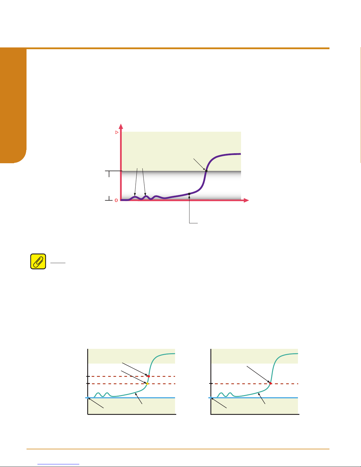
Sensor Drift Detection
Drifting in sensors occurs from a number of dierent causes including environmental
contamination, vibration, and extreme temperature uctuations. This can lead to false sensor
readings. The THZ3/TDZ
Alarm to monitor the absolute dierential between two sensors (i.e. RTD & T/C or two RTDs or
T/Cs) at the same point. This method can provide a range alarm warning or alarm to indicate
that there is an issue with one of the sensors. See Chart below for clarication.
3
can be congured to detect these false readings by using a Range
User’s Manual
238-741-00K
May 2019
SECTION 1
In this example a Range Alarm is set with the Absolute Dierential as the source. An out of
range warning or alarm is congured with the low and high limits set to 0C° to 5C° respectively,
creating an alarm when Sensor 1 and Sensor 2 readings drift apart by more than 5C°.
Note: When setting the drift limit please allow for sensor tolerances and differences in sensor
response times to avoid false drift alerts.
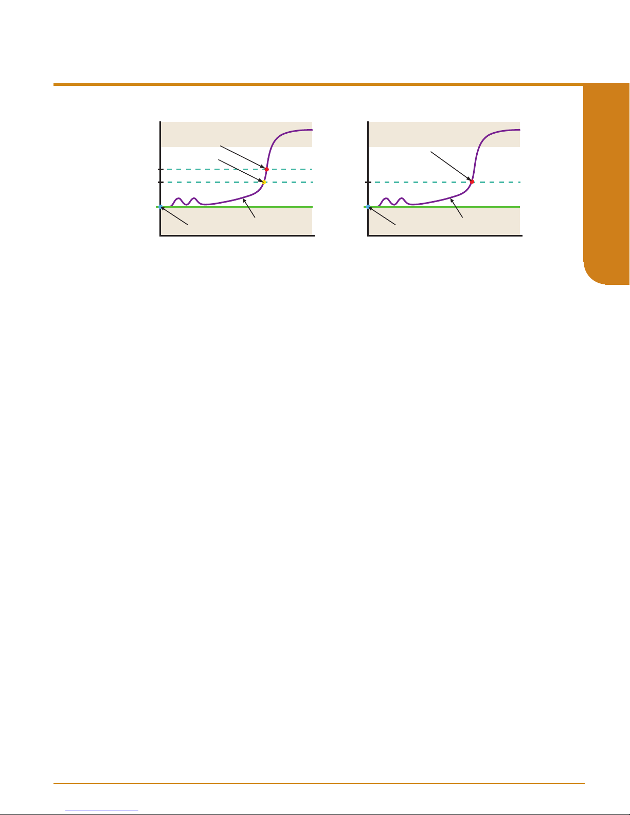
Corrosion Detection
Corrosion of the sensor connections is primarily caused by oxidation or electrolysis which can
lead to inaccurate readings with RTD measurements. The THZ
on 3W or 4W RTDs by measuring the change in compensating lead wire resistance between
terminals 3 and 4 providing an alert when preset value limits are exceeded.
USER
DEFINED
DRIFT
LIMITS
T
Drift Alert
TIME
Activated
Typical Drift Over Time
3
/TDZ3 is able to detect corrosion
Initial
Minimal
Dierence
3
Additionally the THZ
3
/TDZ
monitors the status of T/C circuits. High resistance values in T/C
circuits could indicate a potential impending T/C burnout.
ALARM
40ohms
35ohms
Resistance
2ohms
WARNING
CAPTURED
VALUE
Dierent Values Same Values
www.miinet.com Moore Industries-International, Inc.
RTD WIRE
RESISTANCE
- 12 -
35ohms
2ohms
WARNING
& ALARM
CAPTURED
VALUE
RTD WIRE
RESISTANCE
Page 13
User’s Manual
2ohms
40ohms
35ohms
WARNING
RTD WIRE
RESISTANCE
RTD Wire
Resistance
T/C Circuit
CAPTURED
VALUE
ALARM
2ohms
35ohms
Dierent Values Same Values
RTD WIRE
RESISTANCE
CAPTURED
VALUE
WARNING
& ALARM
238-741-00K
May 2019
3
THZ 3/ TDZ
Programmable Smart HART Temper ature Transmitter
SECTION 1
ALARM
4,000ohms
3,500ohms 3,500ohms
Resistance
200ohms
WARNING
CAPTURED
VALUE
Dierent Values Same Values
T/C CIRCUIT
RESISTANCE
200ohms
WARNING
& ALARM
CAPTURED
VALUE
T/C CIRCUIT
RESISTANCE
To setup Corrosion Detection, the user captures the nominal sensor resistance value and sets
the Warning and Alarm limits. These can be set at dierent levels or the same level for both.
See chart below for clarication.
Selecting Warning will set a fault message on the TDZ3 display and send a HART message to
any HART Handheld or HART monitoring HOST. In addition an alert will be sent to any FDT
host that is communicating with the transmitter. Selecting Alarm will also drive the Analog output
to Fail Mode if the sensor is assigned to the PV. If the unit is in backup mode, and the primary
sensor has a corrosion alarm, the PV will switch to the backup sensor.
Broken Wire Detection
During operation, the THZ
check for broken wiring or a burned out sensor. By default the broken wire detection is always
enabled, and this feature is essential to ensure that dangerous failure of the sensor or signal
input is detected by the THZ3 and TDZ3 and consequently alarmed.
3
and TDZ3 send random microamp pulses through input wiring to
If the THZ3/TDZ
3
detects a broken wire or burned out sensor during operation, the transmitter
sets the output upscale or downscale to warn of trouble. The transmitter is able to identify
sensor wire(s) causing the problem and indicate the fault as a message to the HART Handheld/
FDT HOST, TDZ3 display and by setting a HART status bit. Specic error messages eliminate
the work of removing the sensor or checking all lead wires to diagnose a problem. This feature
is especially valuable during startup.
Additionally the THZ
Time. This allows users to add an additional time delay before the broken wire diagnostic alert
3
and TDZ
3
have another feature referred to as BW (Broken Wire) Holdo
is reported. When enabled, a Broken Wire delay of 0-60 seconds can be set. This feature
prevents the transmitter from going into a fault state when intermittent high levels, or spikes, of
extraneous plant noise is conducted onto the sensor leads.
- 13 -
www.miinet.comMoore Industries-International, Inc.
Page 14

3
THZ 3/ TDZ
Programmable Smart HART Temper ature Transmitter
Section 2 - Calibration and Bench Check
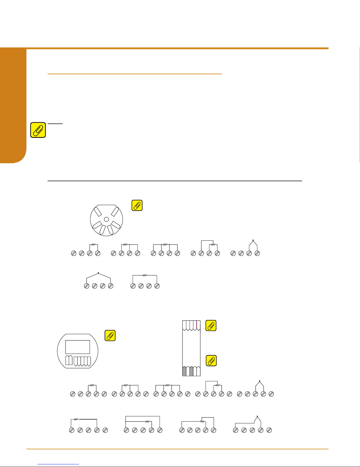
Please refer to Figure 2.1 for proper terminal connections while calibrating or performing a bench
check on your THZ3/TDZ3.
Figure 2.1. Terminal Designations
THZ3 HPP (4 Terminals) Input Connections
SECTION 2
Sensor 1
TB1 TB2 TB3 TB4
2W RTD / Resistance 3W RTD / Resistance
THZ3 HPP
+PS
TB1
TB2
-PS
TB4
TB3
TB1 TB2 TB3 TB4
3
Note: THZ
[HPP] (see gure 3.4) – When using two input sensors, Sensor 1
can be congured as 2-wire or 3-wire sensor. Sensor 2 is then restricted to
a 2-wire sensor.
TB1 TB2 TB3 TB4
4W RTD / Resistance
TB1 TB2 TB3 TB4
POTENTIOMETER
+
TB1 TB2 TB3 TB4
THERMOCOUPLE / mV
User’s Manual
238-741-00K
May 2019
-
Sensor 2
+
TB1 TB2 TB3 TB4
THERMOCOUPLE / mV
-
TB1 TB2 TB3 TB4
2W RTD / Resistance
TDZ3 HP and THZ3 DIN (5 Terminals) Input Connections
TDZ
3
Note: TDZ
sensors you are limited to 2-wire
3
– When using two input
and/or 3-wire sensors. 4-wire sensors
(RTDs) cannot be used.
TB1 TB2 TB3 TB4 TB5
3W RTD / Resistance
TB1 TB2 TB3 TB4 TB5
3W RTD / Resistance
Sensor 1
Sensor 2
-PS
+PS
TB1
TB2 TB3 TB4 TB5
TB1 TB2 TB3 TB4 TB5
2W RTD / Resistance
TB1 TB2 TB3 TB4 TB5
2W RTD / Resistance
TB1
TB1 TB2 TB3 TB4 TB5
4W RTD / Resistance
TB1 TB2 TB3 TB4 TB5
POTENTIOMETER
TB2TB3 TB4 TB5
Note: THZ
using two input sensors you are
3
THZ
DIN
+PS
limited to 2-wire and/or 3-wire sensors.
4-wire sensors (RTDs) cannot be used.
Note: *GND is Case Ground terminal
-PS
GND
used for -AIS option only.
TB1 TB2 TB3 TB4 TB5
POTENTIOMETER
3
[DIN] (see gure 3.2) - When
+
TB1 TB2 TB3 TB4 TB5
THERMOCOUPLE / mV
+
TB1 TB2 TB3 TB4 TB5
THERMOCOUPLE / mV
-
-
www.miinet.com Moore Industries-International, Inc.
- 14 -
Moore industries-International, Inc.
Page 15

User’s Manual
ADDR
A
238-741-00K
May 2019
3
THZ 3/ TDZ
Programmable Smart HART Temper ature Transmitter
Calibration
Every THZ3/TDZ3 is calibrated to our specifications prior to delivery to our customers. We
recommend that you check the calibration every year and re-calibrate only when necessary.
Please refer to the Long Term Stability Table in Section 8 of this manual. Calibration by the end
user can be performed in the field by capturing or trimming the input and/or trimming the analog
output.
Sensor trimming increases the measurement accuracy of your instrument by matching the
3
reading of its actual input to its scaling. The THZ
/TDZ3 offers the use of a trimming feature
that can be accessed using a HART Communicator, a HART Host, or an FDT Host (such as
PACTware).
Likewise, output trimming increases the measurement accuracy of the THZ
3
/TDZ3 by calibrating
its analog output to the device that is receiving the output (such as a DCS). This ensures that the
output of the THZ3/TDZ3 is being correctly interpreted.
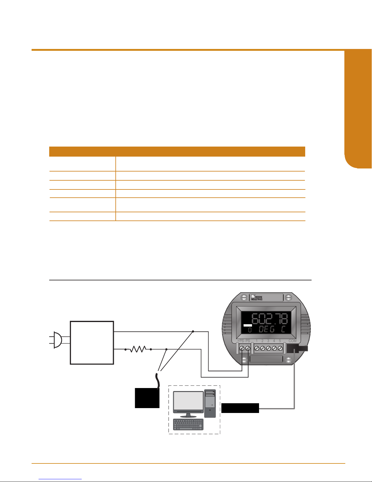
Calibration using a HART handheld communicator
To perform the Input Trimming of the THZ3/TDZ
Figures 2.1 thru 2.4.
Table 2.1. Necessary Equipment
Device
Millivolt or
Resistance Source
Power Supply
Load Resistor
Multimeter
HART Communicator
Specifications
Accurate to ±0.05% of span for the intended application.
24Vdc, ±10%
250 ohms with ±0.01% precision
Calibrated to an accuracy of ±0.025%, or better; such as Fluke Model 725, or similar
Any HART HandHeld Communicator or Host (with THZ
3
set up the equipment in Table 2.1 as shown in
3
/TDZ3 Device Description loaded)
SECTION 2
See Figure 2.2 for the power supply and loop connections. The TDZ3 is shown, but the power
supply and loop connections for the THZ
Figure 2.2. Power Supply and Loop connections
12-24Vdc
Power
Supply
+
-
The HART Communicator
can be connected to any
point on the output side of
the loop. Total loop
resistance must equal
between 250 to 1,100 ohm
for proper HART
Communications
Load= 250 ohm
3
[HPP] and THZ
- 15 -
3
[DIN] will be similar.
ADDR
TDZ
3
www.miinet.comMoore Industries-International, Inc.
Page 16

Process
3
THZ 3/ TDZ
Programmable Smart HART Temper ature Transmitter
Use your HART Communicator to verify how your instrument is congured. Refer to Figure 2.3
below for clarity.
Figure 2.3. Verify Instrument Configuration with HART Communicator
User’s Manual
238-741-00K
May 2019
Online Menu
Mode l
Device Setup
SECTION 2
PV is
PV Quality
PV
PV Loop Current
PV LR V
PV URV
SV
TV
QV
Range Alarm
Status*
.
This will help you to be sure to apply the correct input with which to trim your THZ3/TDZ
example: If the Sensor 1 Measure Mode is “RTD 4 wire” and the Sensor 1 Input Type is “Pt 3850
1000 ohm” and Sensor 1 EGU is “deg F” then you should be using an accurate resistance source
(such as a decade box) to emulate the 4-wire, Pt 3850, 1000Ω RTD and use the Fahrenheit
temperature tables to source the correct resistances for your specic temperature range. Be
sure to also check the HART Communicator’s Online Menu to see your instrument’s PV LRV
(Primary Variable Lower Range Value) and PV URV (Primary Variable Upper Range Value)
settings so that you know the span of temperature to be used.
Process
Variables
Setup
Custom
Calibraon
Review
Defaul t Confi g
Config Wi zards
Input
Dual Input
Anal og Output
HART Sengs
Display
System Config
Adva nce
Sengs
*
Filter
PV Damping
Configure
Sensor
Ranging and
Mapping
Configure
Input Types
RJC Temp
Sensor 1
Sensor 2
Measure Mode
Input Type
EGU
BW Detecon
BW Hold off me
Running Average
2Wire Offset
Sensor Inform aon
Scaling
Custom Curve*
3
. By
Now you are ready to do the actual input trimming of your THZ3/TDZ
Communicator, follow Figure 2.4 below and steps on next page for clarity.
Figure 2.4. Input Trimming with HART Communicator
Online Menu
Mode l
Device Setup
PV is
PV Quality
PV
PV Loop Cu rrent
PV LR V
PV URV
SV
TV
QV
Range Alarm
Status*
www.miinet.com Moore Industries-International, Inc.
Vari ables
Setup
Custom
Calibraon
Review
Status
Input (PV) Capture
Variable Trim
AO Trim
AO Trim Reset
Loop Test
Input Simu laon
S1 Corrosi on Det
S2 Corrosi on Det
Unla tch RA
*
- 16 -
3
. Using your HART
Device Va ri able Trim
Device Va ri able Trim Reset
Display Device Variable Trim
Sensor 1
Sensor 2
Moore industries-International, Inc.
Page 17

User’s Manual
ADDR
A
238-741-00K
May 2019
3
THZ 3/ TDZ
Programmable Smart HART Temper ature Transmitter
1. From the Online menu select “Device setup”.
2. Select “Custom Calibration”.
3. Select “Variable Trim”.
4. Select “Device variable trim”.
5. Follow and heed the information and instructions on the screen of your HART
Communicator.
6. Select “Sensor 1”.
7. Select “Trim Low”.
8. You will now be setting your input resistance to match your PV LRV. For example – If your
LRV is 32° F the input you will apply to the instrument will be 1000.00Ω.
9. When your reading stabilizes press the OK button to capture the value and follow the
prompts.
10. Follow the screen prompts to trim the PV URV.
11. Save the trim values and return your instrument to loop control and verify that your input is
reading correctly.
12. You can then perform the Variable Trim for Sensor 2 if you are using a dual sensor
configuration.
Trimming for a thermocouple input will be similar, except you will be providing an accurate
millivolt signal to simulate temperature.
SECTION 2
3
To perform the Output Trimming of the THZ
then use your HART Communicator, follow steps below and refer to Figure 2.5 for clarity.
Figure 2.5. Output Trimming
12-24Vdc
Power
Supply
+
-
Load= 250 ohm
Voltmeter
3
/TDZ
set up the equipment specied in Table 2.1.
ADDR
The HART Communicator
can be connected to any
point on the output side of
the loop. Total loop
resistance must equal
between 250 to 1,100 ohm
for proper HART
Communications
TDZ
3
Note: You do not need to connect any sensor to the input terminals to perform the output trim.
- 17 -
www.miinet.comMoore Industries-International, Inc.
Page 18

Process
3
THZ 3/ TDZ
Programmable Smart HART Temper ature Transmitter
Figure 2.6. Output Trimming with HART Communicator
User’s Manual
238-741-00K
May 2019
Online Menu
Mode l
Device Setup
PV is
SECTION 2
1. From the Online menu select “Device setup”.
2. Select “Custom Calibration”.
3. Select “AO Trim” (this allows you to trim the Analog Output)
4. Start with the “Trim Zero” function.
5. Follow and heed the information and instructions on the screen of your HART
6. Use your voltmeter to measure the voltage drop across the 250Ω resistor. A 4mA output
7. Follow the instructions on the screen of your HART Communicator and then proceed to
8. Use your voltmeter to measure the voltage drop across the 250Ω resistor. A 20mA output
PV Quality
PV
PV Loop Current
PV LRV
PV URV
SV
TV
QV
Range Alarm
Status*
Communicator.
will read as 1V across the resistor.
“Trim Full”.
will read as 5V across the resistor.
Vari ables
Setup
Custom
Calibraon
Review
Status Reset Trim
Input (PV) Capture Trim Zero
Variable Trim
AO Trim
AO Trim Reset
Loop Test
Input Simulaon
S1 Corrosion Det
S2 Corrosion Det
Unla tch RA
*
Trim Full
www.miinet.com Moore Industries-International, Inc.
- 18 -
Moore industries-International, Inc.
Page 19
User’s Manual
ADDR
A
238-741-00K
May 2019
3
THZ 3/ TDZ
Programmable Smart HART Temper ature Transmitter
Calibration using FDT/DTM Software
This section provides information on calibrating the TDZ3/ THZ
FDT frame application). For users who already have an FDT Frame Application, all the following
information is still relevant. For more information on FDT/DTM please refer to www.fdtgroup.org.
To perform the Input Trimming of the THZ3/TDZ
3
set up equipment in Table 2.2 as shown in
Figure 2.7.
Table 2.2. Necessary Equipment
Device
Millivolt or
Resistance Source
Power Supply
Load Resistor
Multimeter
PC with PACTware
or FDT frame application
Communications Cable
For instructions on installation and setup of the THZ
Specifications
Accurate to ±0.05% of span for the intended application.
24Vdc, ±10%
250 ohms with ±0.01% precision
Calibrated to an accuracy of ±0.025%, or better; such as Fluke Model 725, or similar
PACTware version 4.1 SP3 or newer
Moore Industries P/N 803-040-26 or 804-030-26
3
/TDZ
frame, please refer to section 5. See Figure 2.7 for the power supply and loop connections. The
3
TDZ
is shown, but the power supply and loop connections for the THZ3 [HPP] and THZ
will be similar.
3
using a PC with PACTware (an
3
DTM with PACTware or another FDT
3
[DIN]
SECTION 2
Figure 2.7. Calibration Setup for PACTware
12-24Vdc
Power
Supply
+
-
Load= 250 ohm
HART Modem
connects to
Serial/USB
COM Port of PC
PC
ADDR
3
TDZ
Moore Industries
P/N: 804-030-26
To USB
Port of PC
- 19 -
www.miinet.comMoore Industries-International, Inc.
Page 20

3
THZ 3/ TDZ
Programmable Smart HART Temper ature Transmitter
Use PACTware to verify how your instrument is configured. Refer to Figure 2.8 below.
Figure 2.8. Verify your sensor type
SECTION 2
User’s Manual
238-741-00K
May 2019
Check the Configure Sensors settings in PACTware. This will help you to be sure to apply the
correct input with which to trim your THZ3/TDZ
and the Type is “Pt3850-1000” and Engineering Units is “degrees Celsius” then you should be
using an accurate resistance source (such as a decade box) to emulate the 3-wire, Pt 3850,
1000Ω RTD and use the Celsius temperature tables to source the correct resistances for your
specific temperature range.
www.miinet.com Moore Industries-International, Inc.
3
. By example: If the Sensor 1 Input is “3W RTD”
- 20 -
Moore industries-International, Inc.
Page 21

User’s Manual
238-741-00K
May 2019
3
THZ 3/ TDZ
Programmable Smart HART Temper ature Transmitter
Figure 2.9. Verify your sensor range
SECTION 2
Check the Ranging and Mapping settings in PACTware. In Figure 2.9 you can see that Sensor 1
is mapped to the Primary Variable and the range is dened as 0-100 Degrees C.
Now you are ready to do the actual input trimming of your THZ3/TDZ
in PACTware as seen in Figure 2.10.
- 21 -
3
. Proceed to Sensor 1 Trim
www.miinet.comMoore Industries-International, Inc.
Page 22

3
THZ 3/ TDZ
Programmable Smart HART Temper ature Transmitter
Figure 2.10. Sensor 1 Trim
SECTION 2
User’s Manual
238-741-00K
May 2019
The Trim Mode can be set for One Point or Two Point. If interested in obtaining the best
accuracy at one temperature point, choose the One Point mode. The most common Trim Mode
is Two Point. This mode yields greater measurement accuracy over a temperature range by
trimming points on each side of a specic range or by trimming at your Zero and Full scale
values (as congured in the Ranging and Mapping screen). The below example outlines a Two
Point trim at the Zero and Full scale points..
Note: The current Sensor 1 Reading is -2.53° C.
Perform the following steps -
1. Set Trim Mode to “Two Point”
2. Set your input resistance to match your Sensor 1 Zero point. By example – If your Sensor 1
Zero point is 0° C the input you apply to the instrument will be 1000.00Ω.
3. Enter the Sensor 1 Zero value into the eld entitled Desired Trim Point Value. For my example
I will be entering 0 (as my range is dened as 0-100°).
4. When your reading stabilizes press the Trim Lower Point button and your Sensor 1 Reading
should now read the correct Trim Point Value (0 in this example).
5. Enter the Sensor 1 Full value into the eld entitled Desired Trim Point Value. For my example I
will be entering 100 (as my range is dened as 0-100°).
6. Set your input resistance to match your Sensor 1 Full point. By example – If your Sensor 1
Full point is 100° C the input you apply to the instrument will be 1385.00Ω.
7. When your reading stabilizes press the Trim Upper Point button and your Sensor 1 Reading
should now read the correct Trim Point Value (100 in this example).
www.miinet.com Moore Industries-International, Inc.
- 22 -
Moore industries-International, Inc.
Page 23
User’s Manual
238-741-00K
May 2019
3
THZ 3/ TDZ
Programmable Smart HART Temper ature Transmitter
You can then perform Sensor 2 Trim if you are using two input sensors.
Your trim values will be automatically saved to your instrument.
The output of the THZ3/TDZ3 is accurately calibrated prior to delivery to our customers.
However, you may wish to trim the instrument’s analog output to match what you are reading
on your monitoring or control system. By example: if the THZ3 is putting out 12.0mA and your
DCS is reading 11.85mA you can trim the output of the THZ
3
so that the two readings will match.
Note: trimming of the analog output will not aect the HART digital data.
To perform output trimming set up your THZ3/TDZ
Figure 2.11. Output Trimming
12-24Vdc
Power
Supply
+
-
Load= 250 ohm
3
as shown in Figure 2.11.
ADDR
TDZ
3
SECTION 2
Voltmeter
HART Modem
connects to
Serial/USB
COM Port of PC
PC
Moore Industries
P/N: 804-030-26
To USB
Port of PC
- 23 -
www.miinet.comMoore Industries-International, Inc.
Page 24

3
THZ 3/ TDZ
Programmable Smart HART Temper ature Transmitter
Select the Custom Calibration/AO Loop Current Test/Trim option in the conguration menu as
shown in Figure 2.12.
Figure 2.12. Custom Calibration/AO Loop Current Test/Trim
SECTION 2
User’s Manual
238-741-00K
May 2019
The points that will be used for trimming will be the “AO Zero” and the “AO Full” that were
congured earlier. For my example these two points will be 4mA (AO Zero) and 20mA (AO Full).
In the “Output Trim” section of the Parameter screen Set Output to “Lower Output Range”. This
will set the instrument’s output to 4mA. Use your voltmeter to read the voltage drop across the
250Ω resistor and calculate the actual current going through the resistor.
Example: A voltage reading of 1.08v equates to 4.32mA (1.08V ÷ 250Ω = 4.32mA). Enter this
value in the Measured Output Current box and then push the “Trim” button.
www.miinet.com Moore Industries-International, Inc.
- 24 -
Moore industries-International, Inc.
Page 25

User’s Manual
238-741-00K
May 2019
3
THZ 3/ TDZ
Programmable Smart HART Temper ature Transmitter
Now, select the “Upper Output Range”. This will set the instrument’s output to 20mA. Use your
voltmeter to read the voltage drop across the 250Ω resistor and calculate the actual current
going through the resistor.
Example: A voltage reading of 4.91v equates to 19.64mA (4.91V ÷ 250Ω = 19.64mA). Enter
this value in the Measured Output Current box and then push the “Trim” button.
Now that the 2-point output trimming has been done you can test the results by entering an
output value in the “Set Current to” box. Enter 4 (for 4mA) in the box, select the “Set” button and
the instrument’s output will go to 4mA and you can check for a 1V reading across the resistor.
You can then enter 20 and check for a 5V reading across the resistor.
There is no need to press the “Apply” button as all trim changes take immediate eect.
Note: When complete BE SURE to press the “Clear” button to return control of the output back
to your THZ3/TDZ3.
SECTION 2
- 25 -
www.miinet.comMoore Industries-International, Inc.
Page 26

ADDR
A
3
THZ 3/ TDZ
Programmable Smart HART Temper ature Transmitter
Bench Check
We highly recommend that you perform a bench check of your THZ3/TDZ3 prior to installing it in
the eld. Doing this will ensure it is operating within your expectations or requirements.
User’s Manual
238-741-00K
May 2019
Bench Check using a HART Handheld Communicator
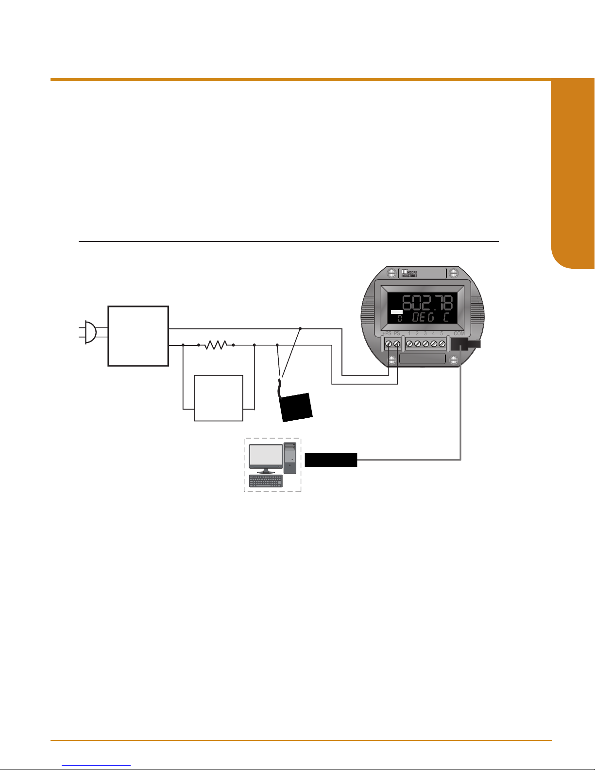
To perform the bench check of your THZ3/TDZ
SECTION 2
Figures 2.13.
Table 2.3. Bench Check Necessary Equipment
Device
Resistance Source
HART Communicator
Millivolt or
Power Supply
Load Resistor
Multimeter
Connect your THZ
THZ3/TDZ
3
as appropriate for your application. If possible, use the exact temperature sensor
(RTD or thermocouple) that you will be using in your nal application. Apply power to the
THZ3/TDZ3 and see that it is reading the correct ambient temperature and providing the correct
output for the given input.
Example: If your TDZ3 is congured to measure a temperature range of 50-100° F and is
now on your test bench and is reading an ambient temperature of 72° then you should
expect an output of 11.04mA.
If it is not feasible for you to use the actual temperature sensor for your bench test, or if your
desired temperature range is nowhere near your ambient temperature, then use a temperature
simulator (such as a Fluke 725 or similar) to provide your input.
3
set up the equipment in Table 2.3 as shown in
Specifications
Accurate to ±0.05% of span for the intended application.
24Vdc, ±10%
250 ohm with ±0.01% precision
Calibrated to an accuracy of ±0.025%, or better; such as Fluke Model 725, or similar
Any HART HandHeld Communicator or Host (with THZ3/TDZ3 Device Description loaded)
3
3
/TDZ
as shown if gure 2.13. See Section 4 of this manual to congure your
Once your bench setup is complete you can now use your FDT/DTM software to check the
transmitter’s dynamic variables and analog output. If using PACTware you can use the
“Measured value” menu command to view the transmitter’s real time values (see Section 5.24 of
this manual).
Figure 2.13. Bench Check Setup
Power
Supply
+
-
HART Modem
connects to
Serial/USB
COM Port of PC
12-24Vdc
www.miinet.com Moore Industries-International, Inc.
Load= 250 ohm
PC
- 26 -
ADDR
3
TDZ
Moore Industries
P/N: 804-030-26
To USB
Port of PC
Moore industries-International, Inc.
Page 27

User’s Manual
238-741-00K
May 2019
3
THZ 3/ TDZ
Programmable Smart HART Temper ature Transmitter
Bench Check using a FDT/DTM Software
This section provides information on checking the TDZ3/ THZ
FDT frame application). For users who already have an FDT Frame Application, all the following
information is still relevant. For more information on FDT/DTM please refer to www.fdtgroup.org.
To perform the bench check of your THZ3/TDZ
3
set up the equipment in Table 2.4 as shown in
Figures 2.14.
Table 2.4. Bench Check Necessary Equipment
Device
Millivolt or
Resistance Source
Power Supply
Load Resistor
Multimeter
PC with PACTware
or FDT frame application
Communications Cable
For instructions on installation and setup of the THZ
Specifications
Accurate to ±0.05% of span for the intended application.
24Vdc, ±10%
250 ohm with ±0.01% precision
Calibrated to an accuracy of ±0.025%, or better; such as Fluke Model 725, or similar
PACTware version 4.1 SP3 or newer
Moore Industries P/N 803-040-26 or 804-030-26
3
/TDZ
FDT frame, please refer to section 5. See Section 4 of this manual to congure your THZ
3
TDZ
as appropriate for your application. If possible, use the exact temperature sensor (RTD
or thermocouple) that you will be using in your nal application. Apply power to the THZ
and see that it is reading the correct ambient temperature and providing the correct output for the
given input.
3
using a PC with PACTware (an
3
DTM with PACTware or another
3
3
/
/TDZ3
SECTION 2
Example: If your TDZ3 is congured to measure a temperature range of 50-100° F and is now
on your test bench and is reading an ambient temperature of 72° then you should expect an
output of 11.04mA.
If it is not feasible for you to use the actual temperature sensor for your bench test, or if your
desired temperature range is nowhere near your ambient temperature, then use a temperature
simulator (such as a Fluke 725 or similar) to provide your input.
Once your bench setup is complete you can now use your FDT/DTM software to check the
transmitter’s dynamic variables and analog output. If using PACTware you can use the
“Measured value” menu command to view the transmitter’s real time values (see Section 5.24 of
this manual).
Figure 2.14. Bench Check Setup
12-24Vdc
Power
Supply
+
-
Load= 250 ohm
Voltmeter
HART Modem
connects to
Serial/USB
COM Port of PC
ADDR
Moore Industries
P/N: 804-030-26
To USB
Port of PC
TDZ
4-Wire
RTD
3
- 27 -
www.miinet.comMoore Industries-International, Inc.
Page 28
TB1 TB2 TB3 TB4
2W RTD / Resistance 3W RTD / Resistance
TB1 TB2 TB3 TB4
4W RTD / Resistance
TB1 TB2 TB3 TB4
POTENTIOMETER
TB1 TB2 TB3 TB4
2W RTD / Resistance
TB1 TB2 TB3 TB4
POTENTIOMETER
TB1 TB2 TB3 TB4 TB5
POTENTIOMETER
TB1 TB2 TB3 TB4 TB5
4W RTD / Resistance
TB1 TB2 TB3 TB4 TB5
3W RTD / Resistance
TB1 TB2 TB3 TB4 TB5
2W RTD / Resistance
TB1 TB2 TB3 TB4 TB5
THERMOCOUPLE / mV
TB1 TB2 TB3 TB4 TB5
+
-
TB1 TB2 TB3 TB4
THERMOCOUPLE / mV
+
-
TB1 TB2 TB3 TB4 TB5
2W RTD / Resistance
THERMOCOUPLE / mV
TB1 TB2 TB3 TB4
+
-
TB1 TB2 TB3 TB4 TB5
THERMOCOUPLE / mV
+
-
Sensor 1
Sensor 1
Sensor 2
Sensor 2
TB1 TB2 TB3 TB4 TB5
3W RTD / Resistance
-PS
+PS
-PS
+PS
THZ3 HPP
THZ
3
DIN
TDZ
3
TB1
TB2TB3 TB4 TB5
TB2
TB3
TB4
TB1
-PS
+PS
TB1
TB2 TB3 TB4 TB5
THZ3 HPP (4 Terminals) Input Connections
TDZ3 HP and THZ3 DIN (5 Terminals) Input Connections
Note: THZ
3
[HPP] (see gure 3.4) – When using two input sensors, Sensor 1
can be congured as 2-wire or 3-wire sensor. Sensor 2 is then restricted to
a 2-wire sensor.
Note: THZ
3
[DIN] (see gure 3.2) - When
using two input sensors you are
limited to 2-wire and/or 3-wire sensors.
4-wire sensors (RTDs) cannot be used.
Note: TDZ
3
– When using two input
sensors you are limited to 2-wire
and/or 3-wire sensors. 4-wire sensors
(RTDs) cannot be used.
GND
Note: *GND is Case Ground terminal
used for -AIS option only.
3
THZ 3/ TDZ
Programmable Smart HART Temper ature Transmitter
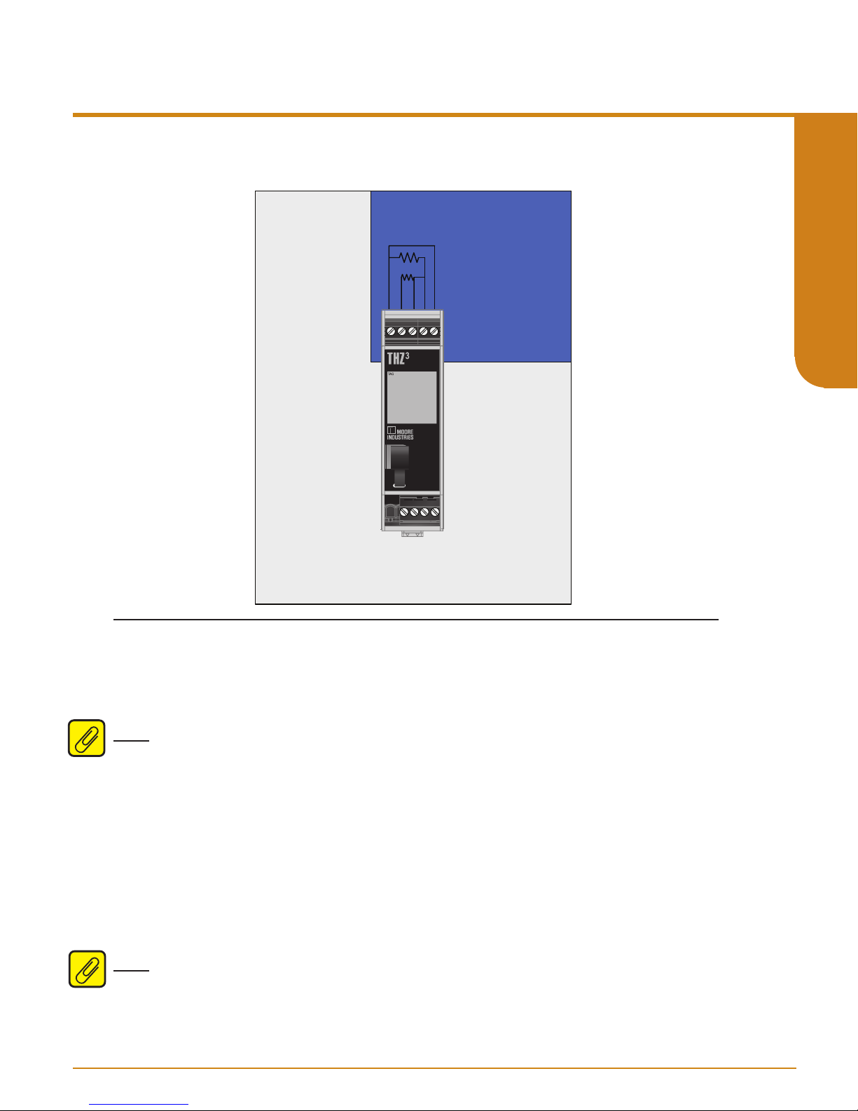
Section 3 - Installation and Wiring
Instructions in this section and others may require special precautions to ensure the safety of the
personnel performing the operations. Notes, Cautions and Warnings that may cause potential
safety issues are indicated throughout this manual by symbols, please refer to Page 3 of this
manual to view and familiarize yourself with these safety message symbols. Figures 3.2 through
3.7 show the various housings and their dimensions.
User’s Manual
238-741-00K
May 2019
SECTION 3
all instruments in their intended application before making any electrical connections. For
DIN rail mounted instruments, allow enough room for pivoting instruments vertically on the rail
for removal in applications involving multiple banks of units. To remove the unit from the DIN
rail you will need a simple tool such as a straight blade screwdriver. Insert the blade of the
screwdriver into the cavity at the bottom of the locking mechanism and rotate it. This will release
the locking mechanism from the DIN rail and allow you to remove the unit.
Terminal Designations
Figure 3.1. Terminal Designations
Note: Make sure to calibrate and bench check the instruments prior to installation. Also, install
www.miinet.com Moore Industries-International, Inc.
- 28 -
Page 29

User’s Manual
ADDRR
238-741-00K
May 2019
3
THZ 3/ TDZ
Programmable Smart HART Temper ature Transmitter
Dimensions
Figure 3.2. Dimensions of Aluminum DIN Housing
SMART HART
TEMPERATURE
TRANSMITTER
DUAL SENSOR
4.04 in
[102.6mm]
1.11 in
[28mm]
Figure 3.3. Dimensions of Aluminum HP Display Housing
75mm
(2.97 in)
5.31 in
[135mm]
75mm
(2.50 in)
SECTION 3
TDZ
62mm
(2.45 in)
Figure 3.4. Dimensions of THZ3 HPP Housing
ADDR
51mm
2.04in
3
32mm
1.27in
48mm
1.90in
33mm
1.30in
- 29 -
www.miinet.comMoore Industries-International, Inc.
Page 30

SIDE VIEW
ADDR
3
THZ 3/ TDZ
Programmable Smart HART Temper ature Transmitter
Figure 3.5. Dimensions of BH2 Housing
102mm
(4.02 in)
SECTION 3
User’s Manual
238-741-00K
May 2019
57mm
(2.24 in)
102mm
(4.02 in)
(0.87 in)
(0.38 in)
(2.68 in)
84mm
(3.31 in)
22mm
10mm
68mm
25mm
(1.00 in)
127.7mm
(5.03 in)
GND
1/2 NPT
TOP VIEW
TDZ
ADDR
ADDR
+PS
-PS12
34
119mm
(4.69 in)
76mm
(2.99 in)
3
68mm
(2.68 in)
124mm
(4.88 in)
www.miinet.com Moore Industries-International, Inc.
- 30 -
Page 31

User’s Manual
ADDR
ADDR
238-741-00K
May 2019
3
THZ 3/ TDZ
Programmable Smart HART Temper ature Transmitter
Figure 3.6. Dimensions of BH3 Housing
124mm
(4.90in)
ADDR
65mm
(2.56 in)
TOP VIEW
62mm
(2.45 in)
57mm
(2.25 in)
70mm
(2.75 in)
76mm
(2.99 in)
44mm
(1.75 in)
89mm
(3.50 in)
115mm
(4.55in)
101mm
(4.0 in)
GND
(1.25 in)
25.4mm
(1.0 in)
SECTION 3
32mm
57mm
(2.25 in)
70mm
(2.75 in)
89mm
(3.50 in)
BACK VIEW
31mm
(1.25 in)
SIDE VIEW
6.6mm
(.26 in)
- 31 -
www.miinet.comMoore Industries-International, Inc.
Page 32

3
THZ 3/ TDZ
Programmable Smart HART Temper ature Transmitter
Figure 3.7. Dimensions of LH Housing
User’s Manual
238-741-00K
May 2019
Safety Lock
(LH2 only)
SECTION 3
Conduit
Entry Port
9mm
(0.35 in)
*LH1 Connection
Head Shown
M4.0 x 0.7
(4 places)
Ground
INSIDE
I.D. 62mm x 19mm Deep
(2.44 in x 0.75 in Deep)
87mm
(3.43 in)
FRONT
Instrument
Mounting Holes
40mm (1.56 in)
Instrument
Mounting
Holes
33mm
(1.30 in)
SIDE*
30mm
(1.18 in)
89mm
(3.5 in)
61mm
(2.40 in)
93mm
(3.68 in)
10-32
Mounting
DIA. 72mm
(DIA. 2.83 in)
2-INCH PIPE MOUNTING HARDWARE
84mm
(3.31 in)
C
L
Holes (2)
61mm
(2.40 in)
BOTTOM
51mm
(2.01 in)
Process Connection
1/2-in NPT (N and M models) or
G½ (BSP) (C models)
2-in Pipe Bracket
Mounting Holes (4)
61mm
(2.40 in)
Metal Tag
www.miinet.com Moore Industries-International, Inc.
- 32 -
Page 33

User’s Manual
(4.65 in)
Conduit
ADDR
TDZ
3
238-741-00K
May 2019
3
THZ 3/ TDZ
Programmable Smart HART Temper ature Transmitter
Figure 3.8. Dimensions of D-Box Housing
118mm
112mm
(4.41 in)
64mm
(2.52 in)
83mm
(3.27 in)
Interior Diameter
81mm (3.2 in)
130mm
(5.12 in)
ADDR
116mm
(4.57 in)
TDZ
SECTION 3
Fitting
Body
Bezel
Cover
3
Instrument
Tag
27mm
(1.06 in)
84mm
(3.31 in)
- 33 -
www.miinet.comMoore Industries-International, Inc.
Page 34

3
THZ 3/ TDZ
Programmable Smart HART Temper ature Transmitter
Electrical Connections
When installing any Moore Industries product, always follow all local regulations and standards
for grounding, shielding, and safety.
WARNING: Terminals on this unit may be connected to hazardous voltages. Before making ANY
connections to this unit, always remove power from the loop or instrument power terminals.
AIS Option
SECTION 3
The THZ3 DIN AIS is an associated apparatus which can be located in a non classified or Class
I Div 2/Zone 2 area with the input terminals connected to equipment in Zone 0/Intrinsically Safe
(I.S.) areas. IS cables need to be segregated; non-I.S. cables (i.e. power, and AO wiring) should
be routed away from I.S. cables (input connections) using suitable cable trunking or other mechanical means.
Warning: If the unit is installed in a hazardous location and/or the input terminals are connected
into the intrinsically safe area then please follow the Special Conditions of Use in the following
sections and installation diagrams in the Certification Information section.
User’s Manual
238-741-00K
May 2019
Installation Category
All terminals are rated CAT I.
Equipment Ratings
The THZ3 and TDZ
and a 4-20mA output. Products connected to the THZ
this type of input.
WARNING: If this unit is used in a manner not specified by Moore Industries, the protection
provided by the equipment may be impaired.
Input/Output Wiring
The Input/Output connections can be made with 14 to 24 AWG (2.5mm2 to 0.2mm
The end of each conductor should be stripped no more than 0.25in (7mm).
Tighten the screws on the terminal block to 4.4 - 5.3 lbf•in (0.5 - 0.6 N•m).
Power Supply Wiring
All power connections should be made with 14 or 16 AWG (2mm2 or 1.3mm2) wire. The end
of each conductor should be stripped no more than 0.25in (7mm). The end of the stripped wire
should be tinned with solder, or inserted into a ferrule and crimped before being placed into a
terminal block. Tighten the screws on the terminal block to 4.4 - 5.3 lbf/in2 (0.5 - 0.6 N/m2).
3
do not generate hazardous voltages, they provide a low voltage (0-1V) input
3
and TDZ3 should be designed to receive
2
) wire.
Protective Earth Conductor
The Protective Earth Conductor shall be of equal or larger size wire than the other two power
conductors. The Protective Earth Conductor shall be the first conductor connected to the unit
when the unit is being wired. It shall be the last conductor removed when the unit is being
un-wired.
www.miinet.com Moore Industries-International, Inc.
- 34 -
Page 35

User’s Manual
238-741-00K
May 2019
3
THZ 3/ TDZ
Programmable Smart HART Temper ature Transmitter
Recommended Ground Wiring Practices
Moore Industries recommends the following ground wiring practices:
• Any Moore Industries product in a metal case or housing should be grounded.
• The protective earth conductor must be connected to a system safety earth ground before
making other connections.
• All input signals to, and output signals from, Moore Industries’ products should be wired
using a shielded, twisted pair wiring technique. Shields should be connected to an earth or
safety ground.
• For the best shielding, the shield should be run all the way from the signal source to the
receiving device. (see Note below)
• The maximum length of un-shielded input and output signal wiring should be 2 inches.
Note: Some of Moore Industries’ instruments can be classified as receivers (IPT2, IPX2, etc.)
and some can be classified as transmitters (TRX, TRY, etc.) while some are both a receiver and
a transmitter (SPA2, HIM, etc). Hence, your shield ground connections should be appropriate for
the type of signal line being shielded. The shield should be grounded at the receiver and not at
the signal source.
CE Certification-related Guidelines
The grounding and wiring practices described above must be followed in order for the unit(s) to
meet the requirements set forth in EMC standard EN61326.
SECTION 3
- 35 -
www.miinet.comMoore Industries-International, Inc.
Page 36
3
THZ 3/ TDZ
Programmable Smart HART Temper ature Transmitter
Installation in Hazardous Locations
This section contains important information regarding installation of THZ
Area Locations.
Note: The THZ3-DIN is suitable for Class I, Division 2, Groups A-D or Non-Hazardous locations
only.
Note: The THZ3-DIN with the -AIS Option is an associated apparatus which is suitable for
SECTION 3
Non-Hazardous or Class I, Division 2/Zone 2 locations with sensor terminals connected to
equipment in Class I, II, III, Division 1/Zone 0 locations.
WARNING:
Do not separate power connector when energized.
WARNING:
Substitution of components is not allowed, as it may impair the intrinsic safety.
AVERTISSEMENT:
La substitution de composants peut compromettre la sécurité intrinséque.
3
and TDZ3 in Hazardous
User’s Manual
238-741-00K
May 2019
WARNING:
To prevent ignition of flammable or combustible atmospheres, disconnect power before
servicing.
AVERTISSEMENT:
Risque d’explosion. Avant de déconnecter l’equipement, couper le courant ou s’assurer que
débrancher tant que l’emplacement est désigné non dangereux.
WARNING:
Explosion Hazard. Do not disconnect equipment when a flammable or combustible atmosphere
is present.
AVERTISSEMENT:
Risque d’explosion. Ne pas débrancher tant que le circuit est sous tension, a moins qu’il ne
s’ agisse d’un emplacement non dangereux.
WARNING:
Explosion Hazard. Substitution of components may impair suitability for Class I, Division 2.
AVERTISSEMENT:
Risque d’explosion. La substitution de composants peut rende ce materiel inacceptable pour les
emplacements de Classe I, Division 2
Maximum operating parameters of the “COM” port for use in Non-Hazardous areas shall not
exceed 3.0V, 300mA and 240mW.
www.miinet.com Moore Industries-International, Inc.
- 36 -
Page 37
User’s Manual
.S. INPUT WIRINGASSOCIATED I
238-741-00K
May 2019
3
THZ 3/ TDZ
Programmable Smart HART Temper ature Transmitter
INTRINSICALLY SAFE
WIRING
SMART HART
TEMPERATURE
TRANSMITTER
DUAL SENSOR
SECTION 3
THZ3 PRG
CLASS I DIV 2/ZONE 2
OR SAFE AREA WIRING
Refer to Figure 3.1 for detailed electrical connections
Specific Conditions of Use
The following instructions must be adhered to when the THZ
locations and potentially explosive atmospheres.
Note: The THZ3-DIN with the -AIS Option has it’s own Specic Conditions of Use. See page 40
for instructions.
3
and TDZ3 is used in hazardous
cFMus Installations
Intrinsically Safe Applications
Class I, Division 1, Groups A-D
Class1, Zone 0, AEx ia IIC, Ex ia IIC
The THZ
rating of at least IP20 and also meets the requirements of ANSI/ISA 61010-1 or
C22.2 No 1010-1. The COM port shall not be used in Hazardous areas.
3
and TDZ3 shall be installed in an enclosure which maintains an ingress protection
Note: Using the box provided on nameplate, the User shall permanently mark type of protection
chosen for the specific installation. Once the type of protection has been marked it shall not be
changed.
- 37 -
www.miinet.comMoore Industries-International, Inc.
Page 38

3
THZ 3/ TDZ
Programmable Smart HART Temper ature Transmitter
Nonincendive, Type n Applications
Class I, Division 2, Groups A-D
Class1, Zone 2, AEx nA IIC, Ex nA IIC
User’s Manual
238-741-00K
May 2019
When installed as Division 2 equipment, the THZ
tool-secured enclosure which meets the requirements of ANSI/ISA 61010-1or C22.2
No. 1010-1 and be capable of accepting the applicable wiring method per the NEC or as
SECTION 3
specied in the C22.1 Canadian Electrical Code, Part I.
When installed as Zone 2 equipment, the THZ
enclosure which meets the requirements of ANSI/ISA 60079-0 or CAN/CSA-E60079-0 and
ANSI/ISA 60079-15 or CAN/CSA 60079-15 and be capable of accepting the applicable wiring
methods per the NEC or as specied in the C22.1 Canadian Electrical Code, Part I. The
enclosure shall, at a minimum, meet the requirements of IP54.
On installation of Zone 2 equipment, the THZ
protection external to the apparatus such that the voltage at the supply terminals of the THZ
3
TDZ
does not exceed 58.8V peak or 58.8Vdc.
The COM port shall not be used in Hazardous areas.
Note: Using the box provided on nameplate, the User shall permanently mark type of protection
chosen for the specific installation. Once the type of protection has been marked it shall not be
changed.
3
and TDZ3 shall be mounted within a
3
and TDZ3 shall be mounted within a tool-secured
3
and TDZ3 shall be mounted within a tool-secured
3
and TDZ3 shall be provided with supply transient
3
and
European Union Installations
(ATEX 94/9/EC Directive)
Intrinsically Safe Applications - Zone 0
II 1 G Ex ia IIC
The THZ
rating of at least IP20.
The communications port shall be programmed through Moore Industries Fuse-Protected USB
Communications Cable, Part No. 804-030-26A, as described on Control Drawings
100-100-80 (TDZ3) or 100-100-81 (THZ3).
The Cable cannot be used in Hazardous Areas or in ambient temperatures in excess of 75° C.
Note: Using the box provided on nameplate, the User shall permanently mark type of protection
chosen for the specific installation. Once the type of protection has been marked it shall not be
changed.
www.miinet.com Moore Industries-International, Inc.
3
and TDZ3 shall be installed in an enclosure which maintains an ingress protection
- 38 -
Page 39

User’s Manual
238-741-00K
May 2019
3
THZ 3/ TDZ
Programmable Smart HART Temper ature Transmitter
Type n Applications – Zone 2
II 3 G Ex nA IIC
When installed as Category 3 equipment, the THZ
tool-secured enclosure which meets the requirements of EN 60079-0 and EN 60079-15 and is
capable of accepting the applicable wiring methods specied in EN 60079-14. The enclosure
shall, at a minimum, meet the requirements of IP54.
On installation, the THZ
to the apparatus such that the voltage at the supply terminals of the THZ
exceed 119V peak or 119Vdc.
The COM port shall not be used in Hazardous areas.
Note: Using the box provided on nameplate, the User shall permanently mark type of protection
chosen for the specific installation. Once the type of protection has been marked it shall not be
changed.
3
and TDZ
3
and TDZ3 shall be mounted within a
3
shall be provided with supply transient protection external
3
and TDZ3 does not
IECEx Installations
Intrinsically Safe Applications - Zone 0
Ex ia IIC
The THZ
rating of at least IP20.
3
and TDZ3 shall be installed in an enclosure which maintains an ingress protection
SECTION 3
The communications port shall be programmed through Moore Industries Fuse-Protected USB
Communications Cable, Part No. 804-030-26A, as described on Control Drawing
100-100-80 (TDZ3) or 100-100-81 (THZ3).
The Cable cannot be used in Hazardous Areas or in ambient temperatures in excess of 75° C.
Note: Using the box provided on nameplate, the User shall permanently mark type of protection
chosen for the specific installation. Once the type of protection has been marked it shall not be
changed.
- 39 -
www.miinet.comMoore Industries-International, Inc.
Page 40

3
THZ 3/ TDZ
Programmable Smart HART Temper ature Transmitter
Type n Applications – Zone 2
Ex nA IIC
User’s Manual
238-741-00K
May 2019
When installed as EPL Gc equipment, the THZ
secured enclosure which meets the requirements of IEC60079-0 and IEC60079-15 and be
capable of accepting the applicable wiring methods for the country of origin. The enclosure shall,
at a minimum, meet the requirements of IP54.
SECTION 3
On installation, the THZ
to the apparatus such that the voltage at the supply terminals of the THZ
exceed 119V peak or 119Vdc.
The COM port shall not be used in Hazardous areas.
Note: Using the box provided on nameplate, the User shall permanently mark type of protection
chosen for the specific installation. Once the type of protection has been marked it shall not be
changed.
Specific Conditions of Use
The following instructions must be adhered to when the THZ3 with –AIS Option is used in
unclassied /non-hazardous locations or hazardous locations/potentially explosive atmospheres.
Note: Programming of the THZ3 through the communication port shall only be done in an
unclassified location using the Moore Industries USB cable, Part Number 804-030-26.
Note: Using the box provided on the nameplate, the user shall permanently mark the type of
protection chosen for the specific installation. Once the type of protection has been marked it
shall not be changed.
3
and TDZ
3
and TDZ3 shall be mounted within a tool-
3
shall be provided with supply transient protection external
3
and TDZ3 does not
cFMus Installations
Class I, II, III, Division 1, Groups A-G
Class I, Zone 0, [AEx ia Ga] IIC, [Ex ia Ga] IIC
Class I, Division 2, Groups A-D
Class I, Zone 2, AEx nA [ia Ga] IIC T4, Ex nA [ia Ga] IIC T4
When installed in unclassied locations:
The THZ3 shall be mounted within a tool-secured enclosure which meets the requirements of
ANSI/ISA 61010-1 or CAN/CSA-C22.2 No. 61010-1 and is capable of accepting the applicable
wiring methods per the NEC or the Canadian Electrical Code. The enclosure shall, at a
minimum, meet the requirements of IP20.
When installed in Division 2 locations:
The The THZ3 shall be mounted within a tool-secured enclosure which meets the requirements
of ANSI/ISA 61010-1 or CAN/CSA-C22.2 No. 61010-1 and is capable of accepting the
applicable wiring methods wiring methods per the NEC or the Canadian Electrical Code.
www.miinet.com Moore Industries-International, Inc.
- 40 -
Page 41

User’s Manual
238-741-00K
May 2019
3
THZ 3/ TDZ
Programmable Smart HART Temper ature Transmitter
When installed in Zone 2 locations:
The THZ3 Temperature Transmitter shall be mounted within a tool-secured enclosure which
meets the requirements of ANSI/ISA-60079-0, ANSI/ISA-60079-15 and ANSI/ISA 61010-1 or
CAN/CSA-C22.2 No. 60079-0, CAN/CSA-C22.2 No. 60079-15 and CAN/CSA-C22.2
No. 61010-1 and is capable of accepting the applicable wiring methods wiring methods per
the NEC or the Canadian Electrical Code. The enclosure shall, at a minimum, meet the
requirements of IP54.
The non-metallic parts incorporated in the THZ3 DIN mount housing may generate an
ignition-capable level of electrostatic charge. The equipment shall not be installed in a location
where the external conditions are conducive to the build-up of electrostatic charge on such
surfaces. Additionally, the equipment shall only be cleaned with a damp cloth.
The THZ3 shall be provided with supply transient protection external to the apparatus such that
the voltage at the supply terminals does not exceed 119Vac peak or 119Vdc.
European Union Installations (ATEX 2014/34/EU Directive)
II (1) G [Ex ia Ga] IIC
II 3 (1) G Ex nA [ia Ga] IIC T4 Gc
SECTION 3
When installed in non-hazardous locations:
The THZ3 shall be mounted within a tool-secured enclosure capable of accepting the applicable wiring
methods specified in EN 60079-14. The enclosure shall, at a minimum, meet the requirements of IP20.
When installed as Category 3 equipment and/or in Zone 2 locations:
The THZ3 shall be mounted within a tool-secured enclosure which meets the requirements of
EN 60079-0 and EN 60079-15 and is capable of accepting the applicable wiring methods specified in
EN 60079-14. The enclosure shall, at a minimum, meet the requirements of IP54.
The non-metallic parts incorporated in the THZ3 DIN mount housing may generate an
ignition-capable level of electrostatic charge. The THZ3 shall not be installed in a location where
the external conditions are conducive to the build-up of electrostatic charge on such surfaces.
Additionally, the equipment shall only be cleaned with a damp cloth.
The THZ3 shall be provided with supply transient protection external to the apparatus such that
the voltage at the supply terminals does not exceed 119Vac peak or 119Vdc.
- 41 -
www.miinet.comMoore Industries-International, Inc.
Page 42

3
THZ 3/ TDZ
Programmable Smart HART Temper ature Transmitter
IECEx Installations
[Ex ia Ga] IIC
Ex nA [ia Ga] IIC T4 Gc
When installed in non-hazardous locations:
User’s Manual
238-741-00K
May 2019
SECTION 3
The THZ3 shall be mounted within a tool-secured enclosure capable of accepting the applicable wiring
methods specified in IEC 60079-14. The enclosure shall, at a minimum, meet the requirements of IP20.
When installed in Zone 2 locations:
The THZ3 shall be mounted within a tool-secured enclosure which meets the requirements of IEC 60079-
0 and IEC 60079-15 and is capable of accepting the applicable wiring methods specified in
IEC 60079-14. The enclosure shall, at a minimum, meet the requirements of IP54.
The non-metallic parts incorporated in the THZ3 DIN mount housing may generate an ignition-ca-
pable level of electrostatic charge. The THZ3 shall not be installed in a location where the exter-
nal conditions are conducive to the build-up of electrostatic charge on such surfaces. Additionally,
the equipment shall only be cleaned with a damp cloth.
The THZ3 shall be provided with supply transient protection external to the apparatus such that
the voltage at the supply terminals does not exceed 119Vac peak or 119Vdc.
www.miinet.com Moore Industries-International, Inc.
- 42 -
Page 43

User’s Manual
238-741-00K
May 2019
3
THZ 3/ TDZ
Programmable Smart HART Temper ature Transmitter
Section 4 - Conguration
The THZ3/ TDZ
an FDT/DTM program. All functions can be configured using either method with the exception
of custom curves which cannot be generated or imported using the HART communicator.
However, once custom curves have been saved in the unit they can be selected using the HART
Communicator.
The following Configuration Overview is applicable to both programming methods. The
remainder of this Section details programming with a HART communicator. For details of
configuring using FDT/DTM please refer to Section 5.
Configuration Overview
The following will be an overview of configuration for the THZ3/ TDZ3.
Usage of the THZ
• Single Sensor
• Dual with “identical” sensors
• Dual with diverse sensors.
When both sensors are being used, and they both produce the same units the measurements
can be combined to provide additional calculated values such as average, differential, low
select etc. The inputs can be either identical (e.g. the same exact RTD) or be different sensors,
producing the same measurement. For a full list of available measurements please see Tables
8.2 through 8.4 in Section 8.
3
can be configured using a HART communicator, HART host or a PC running
3
and TDZ3 can be grouped into three general classifications:
SECTION 4
Note: To use a calculated Device Variable, both sensors’ engineering units (EGU) must be
compatible (i.e. the same, or both temperature units). If a calculated Device Variable has
different engineering units (EGU) from the sensors’ EGU, scaling will need to be used to
change the units.
Single Sensor
The THZ
Note: A single sensor 4W RTD is the factory default configuration. (see Quick start guide for
details)
3
or TDZ
1) Configure the sensor.
a. Use the “Configure Input Types” method to select SEN1, and to have SEN2 disabled.
b. Navigate to the Sensor 1 Configuration menu, and make any additional settings as needed.
2) Assign/Map the Device Variables to the HART Variables (PV, SV etc.) The only Device
Variables available are SEN1 and RJC T. In most cases, SEN1 should be assigned to PV
(Default setting).
3) Configure the PV Range (PV URV and LRV).
4) Configure the AO’s Range, limits, and fail response.
3
can be configured to use a single sensor. Follow these steps:
- 43 -
www.miinet.comMoore Industries-International, Inc.
Page 44

3
THZ 3/ TDZ
Programmable Smart HART Temper ature Transmitter
Dual with Identical Sensors
The THZ3 or TDZ
1) Configure the sensor
a. Use the “Configure Input Types” method to select SEN1, and to use the same sensor for
SEN2
b. Navigate to the Sensor 1 Configuration menu, and make any additional settings as needed
SECTION 4
c. Repeat for Sensor 2
2) Assign/Map the Device Variables to the HART Variables (PV, SV etc.) Any variable can be
assigned to the PV. However in most cases, BU1-2 or AVG will be used as the PV.
3) Configure the PV Range (PV URV and LRV)
4) Configure the AO’s Range, limits, and fail response
Dual with Mixed Sensors
The THZ3 or TDZ
RTD).
Follow these steps:
1) Configure the sensor
3
can be configured for use with two identical sensors. Follow these steps:
3
can be configured for use with two different sensors (for example, T/C and a
User’s Manual
238-741-00K
May 2019
a. Use the “Configure Input Types” method to select SEN1, and select “Configure
Independently” for
b. Navigate to the Sensor 1 Configuration menu, and make any additional settings as needed
c. Repeat for Sensor 2
2) Assign/Map the Device Variables to the HART Variables (PV, SV etc.) Any variable can be
assigned to the PV. However in most cases, BU1-2 or AVG will be used as the PV.
3) Configure the PV Range (PV URV and LRV)
4) Configure the AO’s Range, limits, and fail response
Note: While the THZ3/TDZ3 will accept a dual input sensor configuration the following
limitations apply only when using two input sensors:
TDZ 3 [HP] – 2-wire and/or 3-wire sensors. 4-wire sensors (RTDs) cannot be used.
THZ3 [DIN] (see figure 3.2) - 2-wire and/or 3-wire sensors. 4-wire sensors (RTDs) cannot
be used.
THZ3 [HPP] (see figure 3.4) – Sensor 1 can be configured as 2-wire or 3-wire sensor.
Sensor 2 is then restricted to a 2-wire sensor.
SEN2. Select the proper input mode/type for SEN2
www.miinet.com Moore Industries-International, Inc.
- 44 -
Page 45

User’s Manual
238-741-00K
May 2019
3
THZ 3/ TDZ
Programmable Smart HART Temper ature Transmitter
The following additional features may also be useful:
Sensor Trimming
Sensor Trimming increases the measurement accuracy of your instrument by trimming the
reading of its actual input, to either a calibrated source or the device to which it is connected.
This verifies that the input to the transmitter is being interpreted correctly. You may trim any point
between 0% and 100% along the scale. Note that one-point trimming applies an offset to the
sensor reading, while two-point trimming applies both an offset and a gain.
Trimming can be applied to one or both sensors (SEN1 & SEN2).
Running Average Filter
This function filters the sensor input signal with a user-selected range between 1 and 16. A
higher Running Average Filter setting provides smoother output transitions; however, increases
response time. Conversely, a lower setting provides a faster response time, but may seem more
unstable.
Filter
This setting is used to configure the input filter. The filter is designed to reduce the effects of
mains induced noise. The input filter frequency value should be set to the frequency of the local
AC supply–either 50Hz or 60Hz.
Scaling
Scaling can be applied to any Device Variable including Sensor 1 and Sensor 2. It provides for a
linear transformation from the Device Variable’s units to any other engineering unit (EGU). Two
points are specified (Input minimum, Scale minimum) and (Input maximum, Scale maximum).
SECTION 4
When scaling is enabled, no unit checking is done. It is possible to convert the value from one
unit to another by configuring for unity scaling eg, (0, 0 and 100, 100). However this should be
unnecessary.
Custom Curve (Advance Settings)
The unit provides the capability to program 4 independent custom curves (CC1-4) which can be
applied to any available Device Variable to define a non-linear scaling. Each Custom Curve can
contain up to 128 pairs (X, Y) where X is the input and Y the output.
Custom Curves cannot be entered using the HART Communicator, they must be entered via the
FDT/DTM. However, once a custom curve has been saved in the unit it can be assigned and
enabled or disabled using the HART Communicator.
PV Settings
There are a few settings which apply specifically to the PV:
• PV Upper Range Value (URV) and Lower Range Value (LRV): Used to scale the PV to
the Percent of Range and Loop Current values. These settings are independent from any
other scaling settings.
• PV Damping: PV Damping allows you to introduce a delay into the response of your unit in
order to stop short-lived spikes from initiating faults and generating fault messages. The
damping time setting is the time PV takes to make a 63% change in response to a step
change.
- 45 -
www.miinet.comMoore Industries-International, Inc.
Page 46
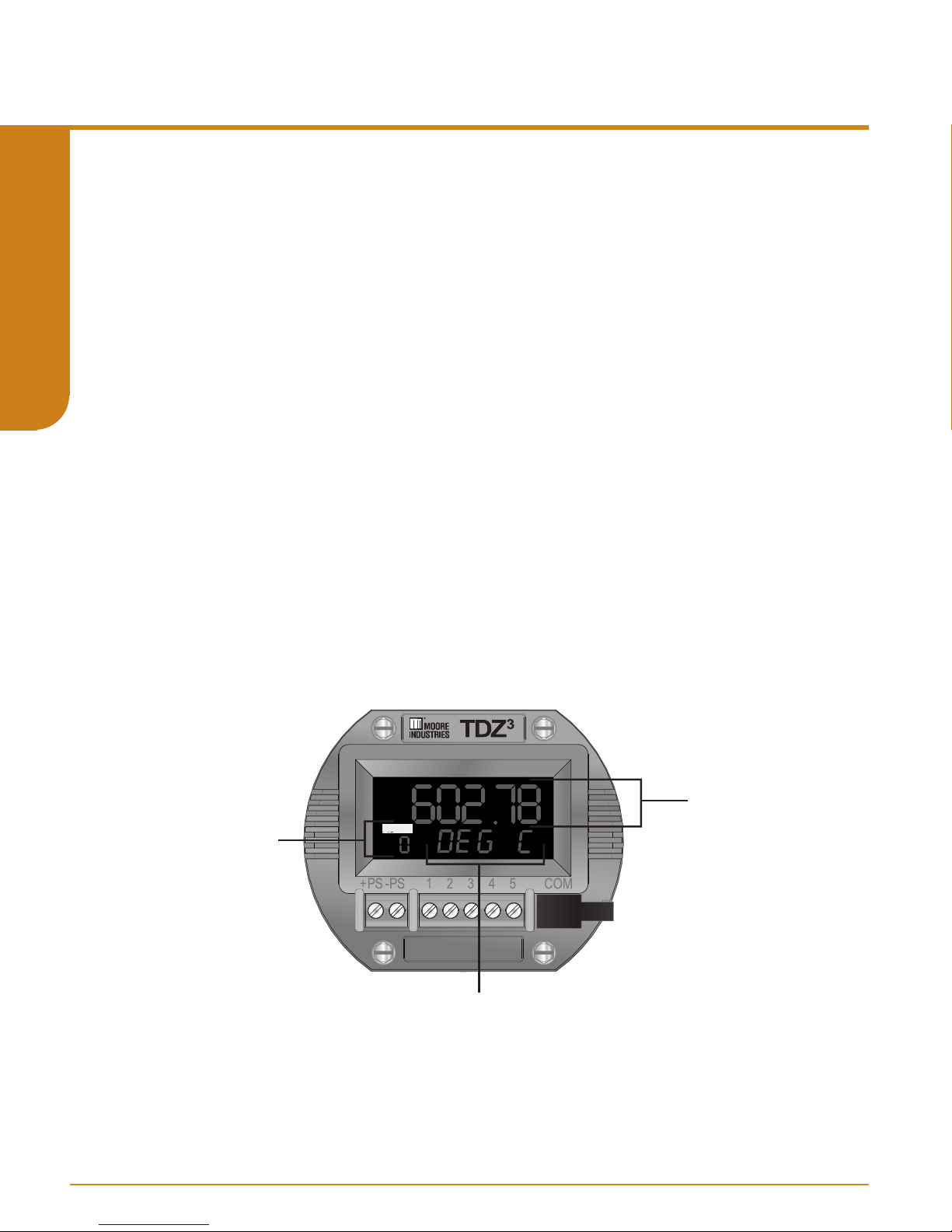
3
THZ 3/ TDZ
Programmable Smart HART Temper ature Transmitter
Analog Output
The system will scale the PV from its LRV/URV (Lower Range Value / Upper Range Value) range
to the AO’s Zero/Full range. As the PV exceeds this range, the AO will continue linearly until it
reaches the AO URV (AO Under Range Value) or AO ORV (AO Over Range Value), where it
“flatlines.” At this point, the output is considered saturated, and will be limited to that value.
If the PV’s data quality goes BAD, or a system error is detected which should result in the
programmed fail response, the AO will respond as configured by either:
SECTION 4
• Fail High to 23.6 mA
• Fail Low to 3.6 mA
• Hold Last Value
• Fail to a Preset Value, configurable between 3.6 and 23.6mA
Analog Output Trimming
AO Trimming increases the accuracy of your instrument by calibrating its analog output to the
device that is receiving the output. This ensures that the instruments are matched to each other.
Display (TDZ
All dynamic and additional device variables in the transmitter can be selected for display. If none
are selected, then the unit will behave as though the PV is marked for display. A “screen” of data
includes the two main rows of characters on the display. Normally, a floating point value is shown
on the top with a text message on the bottom row. Some items require more than one screen to
be displayed. Each screen is shown for 2 seconds. If the value being displayed changes, it will
be updated while that screen is being shown.
3
only)
User’s Manual
238-741-00K
May 2019
HART
ADDRESS
www.miinet.com Moore Industries-International, Inc.
FLOATING
POINT
VALUE
ADDR
Message
eg, EGU, variable name,
measurement mode,
error message
- 46 -
Page 47

User’s Manual
238-741-00K
May 2019
3
THZ 3/ TDZ
Programmable Smart HART Temper ature Transmitter
HART Broadcast Messaging (Burst Mode)
When set to burst mode, the THZ
the host to request them. This enables event driven communication (high, low, deviation of signal
or change in status) and/or timed communication (every x seconds) to the host.
Note: When using burst mode in the THZ3/TDZ3, the host must also be configured to
communicate in burst mode.
Up to 3 different burst messages may be configured independently in the THZ
burst message the following parameters need to be configured:
HART Command – determines which parameters are sent in the message
Update Periods – specifies the minimum and maximum time between messages
Trigger – determines what triggers a message to be sent to the host
Slot 1-8 – For HART commands 9 and 3 only, select the device variables for the message
The following HART commands can be selected for the burst message:
Command Variables in burst message Trigger Source
1 Primary Variable (PV) PV
2 Loop current and Percent of Range (POR) POR
3
/TDZ3 will proactively send out messages instead of waiting for
3
3
/TDZ
. For each
SECTION 4
3 Dynamic Variables and Loop Current PV
9 Device Variables with status Device Variable in Slot 1
33 Device Variables Device Variable in Slot 1
48 Additional Device Status Status bits
Update Periods: The Update and Maximum Update periods determine the minimum and
maximum time interval between each message. The update periods can be set to the following
values:
0.5, 1, 2, 4, 8, 16, 32, 60-3600 seconds
The actual frequency of messages sent will be determined by the update periods and trigger
mode.
If the trigger mode is set to Continuous, then the message will be sent every x seconds where x is
the Update period.
If the trigger mode is set to any other value (i.e. it is looking for a trigger) then the message will be
sent every x seconds (update period) if the trigger condition is met. If the trigger condition is not
met then a message will be sent every y seconds where y is the Maximum Update period. This
ensures that the device and host communicate regularly (once per hour if y is set to the maximum
value of 3600 seconds).
- 47 -
www.miinet.comMoore Industries-International, Inc.
Page 48

3
THZ 3/ TDZ
Programmable Smart HART Temper ature Transmitter
Trigger: This determines what triggers a message to be sent to the host. The trigger source value
depends on the HART command and is defined above.
There are three parameters which need to be set for the trigger - mode, level and units
Mode Level Units Description
Continuous 1.0*** Not used Messages will be sent every x seconds where x is the
Update period
User’s Manual
238-741-00K
May 2019
SECTION 4
Window positive value set* Messages will be sent if the reading increases or
decreases by the window value
Rising any** set* Messages will be sent if the reading is above the
trigger value (High alarm)
Falling any** set* Messages will be sent if the reading is below the
trigger value (Low alarm)
On Change 1.0*** Not used Used for command 48 to detect any status change
*Units must match the trigger source units. If the units do not match then trigger mode becomes inactive.
** The trigger level can be any value in the trigger source range.
*** For continuous and level modes the trigger level and units are not applicable. The level is set to 1.0 by
default.
In all cases, burst messages are sent every x seconds (Update Period) if the trigger condition is
met. If the trigger condition is not met, the update time will drop to the Maximum Update Period.
Slots 1-8: For commands 9 and 33, the Device Variables which will be sent in the message
need to be selected. By default all slots are set to ‘Not Used’. Only Slots 1-4 can be assigned for
Command 33.
If a trigger condition is set, Slot 1 must have a Device Variable assigned and this will be used as
the trigger source.
Burst message examples:
Read PV every second
Burst message settings: HART command 1:Read PV
Update period: 1 second
Maximum update period: 1 second
Trigger Mode: Continuous
Trigger Level: 1.0
Trigger Units: (250) Not Used
Read Dynamic Variables and Loop Current every second when PV exceeds 50degC or
every 5 minutes (when PV does not exceed 50degC)
HART command 3: Read Dynamic Variables and Loop Current
Update period: 1 second;
Maximum update period: 300 seconds
Trigger Mode: Rising
Trigger Level: 50.00
Trigger Units: degrees Celsius
www.miinet.com Moore Industries-International, Inc.
- 48 -
Page 49

User’s Manual
238-741-00K
May 2019
3
THZ 3/ TDZ
Programmable Smart HART Temperature Transmitter
Read Additional Device status every 0.5 second if there are any status changes or every
hour if there are no status changes
HART command 48: Read Additional Device Status
Update period: 0.5 seconds;
Maximum update period: 3600 seconds
Trigger Mode: Change
Trigger Level: 1.0
Trigger Units: (250) Not Used
Sensor Diagnostics
Sensor Drift Alert using Range Alarms and Sensor Corrosion Detection can also be used for
predictive diagnostics to warn of future problems.
Broken Wire Holdoff Time allows you to add an additional time delay before a sensor broken
wire is reported which provides some noise immunity and prevents false alarms caused by other
factors that may be misinterpreted as Broken Wire.
Please refer to Section 1 for more detailed information on Sensor Diagnostics.
Input Quality Alarms
The THZ3/TDZ3 also allows the user to determine how certain types of input quality issues are
handled and how they can affect the Device Variables, Dynamic Variables and AO. There are
3 different quality alarms: Measurement out of Conformance Range, Allow Limited and Allow
Dropping. See Section 6 for more information.
SECTION 4
- 49 -
www.miinet.comMoore Industries-International, Inc.
Page 50

3
THZ 3/ TDZ
Programmable Smart HART Temperature Transmitter
User’s Manual
238-741-00K
May 2019
Programming Device Description Menu on THZ
Communicator handheld devices
To program your TDZ3 or THZ
Description for your instrument. Please follow the steps below to congure instrument. Refer to
Figure 4.1 for an outline of menu options.
SECTION 4
3
/TDZ3 with HART
3
, your HART communicator must be equipped with the Device
Online Menu
The Online menu displays the current process value of your application, the lower and upper
range values and the actual output current. Use the Device Setup menu to congure the TDZ3
or THZ3 as detailed in the rest of this section.
Note: In the following configuration information, all default values are shown in [ ] .
Note: When making changes or updates within menus you will notice the menu item is
highlighted and an asterisk ( * ) appears in front of the menu item changed/updated. This
indicates that a change/update was made yet not updated on the unit itself. To insure that
changes/updates are implemented, you must hit the SEND button to refresh and update the
THZ3/ TDZ3 unit. Hitting the HOME button or the BACK arrow will cancel the desired change/
update.
www.miinet.com Moore Industries-International, Inc.
- 50 -
Page 51
User’s Manual
238-741-00K
May 2019
3
THZ 3/ TDZ
Programmable Smart HART Temperature Transmitter
Figure 4.1. TDZ
Online Menu
Mode l
Device Setup
PV is
PV Quality
PV
PV Loop Cu rrent
PV LRV
PV URV
SV
TV
QV
Range Alarm
Status*
.
* These menu opons are only available when "Advanced Sengs" is enabled
3
or THZ
Process
Vari ables
Setup
Custom
Calibraon
Review
3
Configuration Online menu overview
PV
PV Quality
PV Loop Current
PV is
PV Damp ing
PV % rnge
Dynamic
Vari ables
Device
Vari ables
Defaul t Confi g
Config Wi zards
Input
Dual Input*
Anal og Ou tput
HART Sengs
Display
System Config
Adva nce
Sengs
Status
Input (PV) Capture
Vari able Trim
AO Tr im
AO Tr im Reset
Loop Te st
Input Simu laon
S1 Corrosion Det...
S2 Corrosion Det...
Unla tch RA*
Device Parameters
Device Inform aon
PV
PV Quality
PV is
SV
SV Qu ality
SV is
TV
TV Quality
TV is
QV
QV Qu ality
QV is
Filter
PV Damp ing
Configure
Sensor
Ranging an d
Mapp ing
Backup 1-2
Backup 2-1
Av erage
Differen al 1-2
Differen al 2-1
Absolute Differenal
Low Select
High Select
Poll Addr
Num req preams
Num resp prea ms
Tag
Long Tag
Descriptor
Message
Date
Fina l asmbly nu m
Dev id
Hardware rev
Burs t Configuraon *
Dyn Var Disp lay Flags
Decimal Places
Dev Var Displa y Flags
Configure Custom EGU*
Configure Custom Name*
Input
Quality
Alar ms
Range
Alar ms*
Disable
Enable
The Sensor Corrosion Sengs is available
only wh en in put ty pe is T/C, 3W/4W RTD
Refresh Device Var
RJC Temp
Sensor 1
Sensor 2
Backup 1-2
Backup 2-1
Average
Differen al 1-2
Differen al 2-1
Absolu te Di f...
Low Select
High Select
Allow Meas Out of Comfor...
Allow Limited
Allow Dropping
Device Va ri able Trim
Device Va ri able Trim Reset
Display Device Variable Trim
Disable
Enable
Basic Wiza rd
Dri Wiza rd
Change Variable Mapping
PV is
Smart Range
SV is
TV is
QV is
DVx re ading
DVx EGU
Scaling
Custom Curve *
AO Ze ro
AO Full
AO URV
AO OR V
Fail Mode
Fail AO
Burst Message 0
Burst Message 1
Burst Message 2
Range Alarm 1
Range Alarm 2
Range Alarm 3
Range Alarm 4
Unlatch RA
Sx Corr Detecon
Sx Corr Res
Sx Corr Warn Le vel
Sx Corr Error Level
Sx Corr Base re s
Capture Base Value
Configure
Input Types
RJC Temp
Sensor 1
Sensor 2
Mode
Cmd
Update Per
Max Update Per
Trig Mode
Trig Units
Trig Level
PCT
AO
PV
Note: Any 2, 3, 4
SV
or all can be
TV
selected to display
QV
in scrolling
Enabled
Source
Response
Mode
Low
High
Latching
Syst em Stat us
Addl St atus Byte s
Subsystem Stat us
Input Status
User Cfg Status
Dev Variable Status
Sensor 1
Sensor 2
Sensor 1
RJC Temp EGU
Measure Mode
Input Type
EGU
BW Detecon
BW Holdoff me
Running Average
2Wire Offset
Sensor Informa on
Scaling
Custom Curve*
PV is (DVX)
(DVX) LSL
(DVX) USL
(DVX) Min Span
(DVX) EGU
PV LRV
PV URV
DVx CC En
DVx CC EGU
DVx CC ID
RJC Temp
SEN1
SEN2
Backup 1-2
Backup 2-1
Average
Differen al 1-2
Differen al 2-1
Absolu te Di f...
Low Select
High Select
Warnin g
Alar m (AO Fail)
Out of range
In range
Tag
Long Tag
Descriptor
Messag e
Date
Dev id
Final asmbly num
Universal rev
Fld dev rev
Sowar e rev
Hardware rev
Poll addr
Num req pr eams
Num resp preams
Burst message 0,1,2*
4000 ohms
2W
...
3W
Pt3850 100
4W
If ohms &
If mV & T/C
Pt3850 200
…
RTD
Disable
Enable
Sx USL
Sx LSL
Sx Min Span
Sx s/n
Scaling Enab led
DVx EGU
DVx Input Min.
DVx Input Max.
DVx Scale Min.
DVx Scale Max.
Model
PV is
SV is
TV is
QV is
[PV Sour ce DEV] LSL
[PV Sour ce DEV] USL
[PV Sour ce DEV] Min Span
PV LRV
PV URV
[PV Sour ce DEV] EGU
Sensor 1 EGU
Sensor 2 EGU
Back up 1-2 EGU
Back up 2-1 EGU
Aver age EGU
Differe nal 1-2 EGU
Differe nal 2-1 EGU
Absolute Differe nal EG U
Low Select EG U
High Sele ct EGU
Sensor 1 Input Type
Sensor 1 s/n
Sensor 2 Input Type
Sensor 2 s/n
Filter
PV Damping
SEN1 Broken Wire Detecon
SEN1 BW Thresh old
SEN1 BW Holdoff m e
SEN1 Runnin g Average
SEN2 Broken Wire Detecon
SEN2 BW Thresh old
SEN2 BW Holdoff m e
SEN2 Runnin g Average
AO Zero
AO Full
AO URV
AO ORV
Fail Mode
AO Fail To Value
RA1 Enabled / Disabled*
RA2 Enabled / Disabled*
RA3 Enabled / Disabled*
RA4 Enabled / Disabled*
1000 mV
...
J, K, E
…
Sensor 2
SECTION 4
- 51 -
www.miinet.comMoore Industries-International, Inc.
Page 52

3
THZ 3/ TDZ
Programmable Smart HART Temperature Transmitter
DD Device Setup Reference Guide
The following provides a comprehensive list of conguration menus and options which can
be used as a quick reference guide to identify the dierent conguration capabilities and
locate them in the menu system. For more information on the specic features please refer
to the Conguration Overview and the specic menu descriptions.
Note: * Is used to identify advanced features which are only accessible by enabling Advanced
SECTION 4
Settings in the SETUP menu.
Process Variables
This menu is for information only. It displays PV parameters and values and allows selection
of all Dynamic and Device Variables to display their present values and quality.
Setup
Default Config- Reset to factory default (see Quick Start Guide for default configuration settings)
Config Wizards- Configuration Wizards to simplify programming:
Basic Wizard – Configures a single sensor or dual identical sensors
Drift Wizard – Set up a Drift Alert between two sensors (see Section 1 Sensor
Diagnostics)
User’s Manual
238-741-00K
May 2019
Input
Filter – 50Hz or 60Hz input filter to reduce mains induced noise
PV Damping – introduces a delay in the response to stop input noise from generating
output errors
Configure Sensor:
Input Type (eg. Thermocouple TypeK, 4W RTD Pt3850 100ohm etc.)
RJC Temp EGU
Sensor 1 /2 EGU (engineering units)
Sensor 1 /2 Broken Wire detection & hold off
Sensor 1/2 Running Average filter
Sensor 1/2 2 wire offset (2W RTD/resistance only)
Sensor 1/2 Information (Limits, span, serial number)
Sensor 1/2 Scaling
*Sensor 1/2 Custom Curve
Ranging & Mapping
Variable Mapping- assigns the Device Variables (eg. SEN1, BU1-2) to the
HART Variables (PV, SV etc.)
Smart Range –sets the PV lower range and upper range values to AO 0-100%
www.miinet.com Moore Industries-International, Inc.
- 52 -
Page 53

User’s Manual
238-741-00K
May 2019
3
THZ 3/ TDZ
Programmable Smart HART Temperature Transmitter
*Dual Input
Congure Scaling and Custom Curve for all the calculated Device Variables
Analog Output
AO Zero & Full Values
AO Under Range & Over Range Values
AO Fail Mode (High, Low, Hold Last, Fail to Value)
HART Settings
Allows configuration of HART parameters:
Polling Address
Number of HART request preamble characters (read only)
Number of HART response preamble characters
Tag, Long Tag, Descriptor, Message, Date, Final assembly number
Device id, Hardware revision (read only)
*Burst Configuration - can be configured to send out up to 3 burst
messages
Display (TDZ3 only)
Select Dynamic & Device Variables to be displayed
Number of Decimal Places
*Configure Custom EGU & Custom Name
SECTION 4
System Configuration
Input Quality Alarms setup
Allow Measurement Out of Conformance Range
Allow Limited
Allow Dropping
*Range Alarms – configure up to 4 range alarms
Advanced Settings
Disable/Enable
- 53 -
www.miinet.comMoore Industries-International, Inc.
Page 54

3
THZ 3/ TDZ
Programmable Smart HART Temperature Transmitter
Custom Calibration
Status
Provides access to all HART status messages:
Additional Status Bytes
Subsystem Status
Input Status
User Configuration Status
SECTION 4
Input Capture
Used to match the device input and output zero and full scale to a known value.
Variable Trim
Sensor 1/2 Trimming and Reset
Analog Output Status
Device Variable Status
User’s Manual
238-741-00K
May 2019
AO Trim
Analog Output Trimming and Reset
Loop Test
Set Analog Output to a xed mA value
Input Simulation
Clear or Set a simulated Input.
S1/S2 Corrosion Detection
Set up corrosion detection on Sensor 1 and/or 2
*Unlatch Range Alarm
Unlatch any of the 4 Range Alarms.
Review
This menu is for information only. It provides conguration information for:
Device Parameters
Device Information
www.miinet.com Moore Industries-International, Inc.
- 54 -
Page 55

User’s Manual
enabled.
238-741-00K
May 2019
3
THZ 3/ TDZ
Programmable Smart HART Temperature Transmitter
Device Setup Menu
The Device Setup menu allows you to access the following menus: Process Variable, Setup,
Custom Calibration and Review refer to Figure 4.2.
Figure 4.2. TDZ
3
*Available only when
“Adv ance Sengs” is
3
or THZ
Device Setup menu
Online Menu
Mode l
Device Setup
PV is
PV Quality
PV
PV Loop Current
PV LR V
PV URV
SV
TV
QV
Range Alarm
Status*
Process
Variables
Setup
Custom
Calibraon
Review
See Figure 4.3
See Figure 4.4
See Figure 4.14
See Figure 4.17
Process Variable Menu:
The Process Variable menu displays the present values of parameters listed on the
Communicator display which include the selected EGU, PV, PV Quality, PV Loop current,
PV is, PV Damping, PV % Range, Dynamic Variables and Device Variables.
SECTION 4
Dynamic Variables– The Dynamic Variables menu displays the present Dynamic
Variables parameter values.
Device Variables– The Device Variables menu displays the present Device Variables
parameter values. If any Device Variable quality is not good, this will show its data quality
flag instead of its value.
Figure 4.3. TDZ
3
Online Menu
Mode l
Device Setup
PV is
PV Quality
PV
PV Loop Current
PV LRV
PV URV
SV
TV
QV
Range Alarm
Status*
*Available only when
“Adv ance Sengs” is
enabled.
or THZ
3
Process Variable menu
Process
Vari ables
Setup
Custom
Calibraon
Review
PV Quality
PV Loop Current
PV is
PV Damp ing
PV % range
Dynamic
Vari ables
Device
Vari ables
PV
PV
PV Quality
PV is
SV
SV Qu ality
SV is
TV
TV Quality
TV is
QV
QV Qu ality
QV is
Refresh Device Vars
RJC Temp
Sensor 1
Sensor 2
Backup 1-2
Backup 2-1
Average
Differen al 1-2
Differen al 2-1
Absolu te Differenal
Low Select
High Select
- 55 -
www.miinet.comMoore Industries-International, Inc.
Page 56
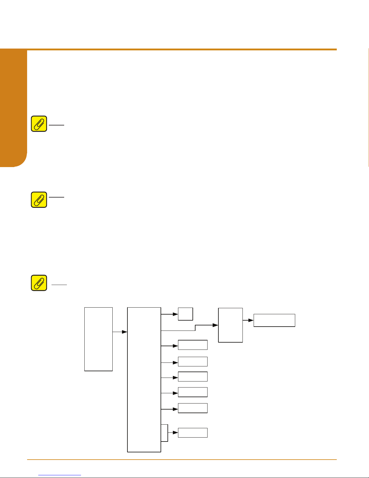
3
THZ 3/ TDZ
Programmable Smart HART Temperature Transmitter
Setup Menu:
The Setup menu allows you to access the following menus:
Wizards, Input, Dual Input, Analog Output, HART Settings, Display, System Cong, and
Advance Settings.
Default Cong– The Default Config menu allows user to reset to factory default settings.
Note: Selecting yes will restore default factory settings to unit and is not reversible.
SECTION 4
Config Wizards:
This menu contains Conguration Wizards to simplify programming of commonly used
features:
Basic Wizard: Basic Wizard can be used to configure either a Single Sensor or Dual
Sensors. Follow the on-screen prompts to set all your parameters.
Note: Selecting the Dual Sensor option will limit your ability to customize parameters of Sensor
2. By default, the wizard sets Sensor 2 parameters to be exactly the same as Sensor 1.
User’s Manual
238-741-00K
May 2019
Default Cong, Cong
Drift Wizard: Use this wizard to setup a Drift Alert that is tracked by monitoring the absolute
differential temperature between two sensors at the same point (the same process temperature).
After selecting a specific Range Alarm (1 to 4) to configure, you can select “Warning” or “Alarm
(AO Fail)”. Selecting Warning sends a message to the HART Handheld/FDT host, TDZ3 display
and sets a HART status bit. Selecting Alarm will also drive the Analog output to Fail Mode. The
absolute differential Device Variable used for the Drift Alert can also be assigned/mapped to any
of the HART Dynamic Variables PV, SV, TV or QV. For more information on the Drift Alert and
Range Alarm features please refer to section 1.
Note: After making all desired changes enter SEND to update the unit.
Figure 4.4. TDZ
3
or THZ
Process
Variables
Setup
Custom
Calibraon
Review
3
Setup menu
Defaul t Confi g
Config Wi zards
Input
Dual Input*
Anal og Output
Yes
No
See Figure 4.5
See Figure 4.9
See Figure 4.10
Basic Wiza rd
Dri Wiza rd
Follow Wiza rd
On-Scree n Instru cons
www.miinet.com Moore Industries-International, Inc.
HART Sengs
Display
System Config
Adva nce
Sengs
See Figure 4.11
See Figure 4.12
See Figure 4.13
- 56 -
Page 57

User’s Manual
238-741-00K
May 2019
3
THZ 3/ TDZ
Programmable Smart HART Temperature Transmitter
Input Menu:
The Setup menu allows you to access the following menus:
Sensor, and Ranging & Mapping.
Filter [60Hz]– This setting is used to configure the input filter. The filter is designed to
reduce the effects of mains induced noise. The input filter frequency value should be set to the
frequency of the local AC supply–either 50Hz or 60Hz.
PV Damping [DISABLED, 0 seconds]– PV Damping allows you to introduce a delay
(0-60 seconds) into the response of your unit in order to stop short-lived spikes from initiating
faults and generating fault messages. The damping time setting is the time PV takes to make a
63% change in response to a step change.
Congure Sensor– The Congure Sensor menu allows you to access to the following list for
conguration: Congure Input Types, RJC Temp, Sensor 1, and Sensor 2 refer to Figure 4.5.
Note: After making all desired changes enter SEND to update the unit.
Figure 4.5. TDZ
Filter
PV Damp ing
Configure
Sensor
Ranging and
Mapp ing
See Figure 4.8
3
or THZ
Input Types
3
Input menu
50 Hz
60 Hz
Configure
RJC Temp
Sensor 1
Sensor 2
Enter
Damping
Time Secs
RJC Temp EGU
See Figure 4.6
Sensor 1 TYPE
1. Resistance
2. mV
3. Potenometer
4. RTD
5. T/C
Filter, PV Damping, Congure
2W
3W
4W
1K
500
250
125
62.5
31.25
2W
3W
4W
1. Off
2. Same as Senor 1
3. Configure
Independantly
Disabled
Enabled
Sensor 2 TYPE
4K
2K
1K
500
250
125
4K
2K
1K
500
250
125
degC
degF
degR
Kelvin
degC
degF
degR
Kelvin
degC
degF
degR
Kelvin
Pt3850 100 ohm
Pt3850 200 ohm
Pt3850 400 ohm
Pt3850 500 ohm
Pt3850 1000 ohm
Pt3902 100 ohm
Pt3902 200 ohm
Pt3902 400 ohm
Pt3902 500 ohm
Pt3902 1000 ohm
Pt3916 100 ohm
Ni6720 120 ohm
Cu 427 9.035 ohm
Type J
Type K
Type E
Type T
Type R
Type S
Type B
Type N
Type C
SECTION 4
- 57 -
www.miinet.comMoore Industries-International, Inc.
Page 58

3
THZ 3/ TDZ
Programmable Smart HART Temperature Transmitter
Configure Input Types:
Selecting this will enable to congure Sensor 1 and Sensor 2 as follows:
Note: While the THZ3/TDZ3 will accept a dual input sensor configuration the following
limitations apply only when using two input sensors:
TDZ 3 [HP] 2-wire and/or 3-wire sensors. 4-wire sensors (RTDs) cannot be used.
THZ3 [DIN] (see figure 3.2) 2-wire and/or 3-wire sensors. 4-wire sensors (RTDs) cannot be
used.
SECTION 4
THZ3 [HPP] (see figure 3.4) Sensor 1 can be configured as 2-wire or 3-wire sensor.
Sensor 2 is then restricted to a 2-wire sensor.
Sensor 1 Type [4W RTD]
Selecting this will prompt the Sensor 1 Type menu screen. Here you can select from
Resistance, mV, Potentiometer, RTD, or T/C. Highlight the desired sensor type and hit enter.
-Resistance:
1. Choose from 2 Wire, 3 Wire, or 4 Wire Connection
2. Select a Resistance value from 4k, 2k, 1k, 500, 250, or 125
3. Sensor 2 Type menu will appear (see below)
-mV:
1. Choose from 1k, 500, 250, 125, 62.5, or 31.25 mV
2. Sensor 2 Type menu will appear (see below)
-Potentiometer:
1. Choose from 4k, 2k, 1k, 500, 250, or 125ohms
2. Sensor 2 Type menu will appear (see below)
-RTD:
1. Choose from 2 Wire, 3 Wire, or 4 Wire Connection Configuration
2. Select temperature unit from degC, degF, degR, or Kelvin
3. Select desired RTD and hit enter
4. Sensor 2 Type menu will appear (see below)
-T/C:
1.Choose between Enabled or Disabled for RJC Temperature compensation. This
should be enabled for the majority of cases. Disable RJC ONLY if you are using a rare
and old remote reference junction wiring strategy
2. Select temperature unit from the following degC, degF, degR, or Kelvin
3. A variety of Thermocouples to choose from select desired T/C and hit enter
4. Sensor 2 Type menu will appear (see below)
Sensor 2 Type [O]:
1. Choose from the following menu options O, Same as Sensor 1, or Congure
Independently.
-Selecting O will turn Sensor 2 o
-Selecting Same as Sensor 1, the conguration parameters from Sensor 1 will be
copied to congure Sensor 2
-Selecting Configure Independently, this will allow you configure parameters of
Sensor 2 separately. (Same menu options as Sensor 1 above)
User’s Manual
238-741-00K
May 2019
www.miinet.com Moore Industries-International, Inc.
- 58 -
Page 59

User’s Manual
238-741-00K
May 2019
3
THZ 3/ TDZ
Programmable Smart HART Temperature Transmitter
RJC Temp:
Selecting this will prompt menu displaying RJC Temp EGU select this. On next menu
screen the current RJC Temp EGU is displayed and you will be able to select new desired
RJC Temp EGU. You may choose for the following degC, degF, degR, or Kelvin. Once
selecting desired RJC Temp EGU next screen will return you to previous RJC Temp
EGU menu at this point you go choose from the following HELP, SEND, or HOME. After
entering SEND you can choose to SAVE, this will prompt menu allowing to choose desired
Location, Name, and Config Type. Refer to Figure 4.5 for clarification.
Note: You must hit the SEND button to refresh and update the THZ3/ TDZ3 unit, otherwise
hitting HOME or BACK arrow will not make or update the desired RJC Temp EGU change/
update.
Sensor 1:
Selecting this will prompt menu displaying:
Refer to Figure 4.6 for clarification.
-S1 Measure Mode: selecting this will display current measuring mode. Enter EXIT to
return to previous screen in Menu.
-S1 Input type: selecting this will display current input type. Enter EXIT to return to
previous screen in Menu.
-S1 EGU Units: selecting this will display current S1 EGU and allow you to change from
the following degC, degF, degR, Kelvin, mV, ohms, or %. Enter ESC if no change is
required. If you choose to change the current S1 EGU select desired unit and hit the
ENTER button to return to previous screen in Menu.
-S1 Broken Wire Detection [Enabled]: selecting this will display whether Sensor 1
Broken Wire Detection is Disabled or Enabled. If you make a change select desired
parameter and hit the ENTER button to return to previous screen in Menu. See Section 1
for more information on Broken wire detection.
-S1 BW Holdoff time [0 seconds]: This allows users to add an additional time delay
before broken wire is detected. When enabled, a Broken Wire delay of 0-60 seconds can
be set which provides some noise immunity and prevents false alarms caused by other
factors that may be misinterpreted as Broken Wire. Selecting this will display current
Sensor 1 Broken Wire Holdoff time and allow you to make changes as required. If you
make a change, select desired parameter and hit the ENTER button to return to previous
screen in Menu.
-S1 Running Average[1]: This function is for filtering the input signal. The TDZ3 and
THZ3 a running average filter with a user-selected range between 1 and 16. Selecting
this will display the current Sensor 1 Running Average and allow you to make changes
as required. If you make a change select desired parameter and hit the ENTER button to
return to previous screen in Menu.
SECTION 4
Note: A higher Running Average Filter setting provides smoother output transitions; however,
increases response time. Conversely, a lower setting provides a faster response time, but may
seem more unstable.
- 59 -
www.miinet.comMoore Industries-International, Inc.
Page 60

3
THZ 3/ TDZ
Programmable Smart HART Temperature Transmitter
-S1 2Wire Offset: This setting is to offset the wire resistance of the 2Wire sensor cable,
and will help the accuracy of the measurement. Selecting this will display current Sensor
1 2Wire Offset and allow you to make changes as required. If you make a change select
desired parameter and hit the ENTER button to return to previous screen in Menu.
-S1 Sensor Information: selecting this will display the Sensor 1, Sensor Information
menu.
SECTION 4
The following will be displayed with your set parameters:
-Sensor 1 USL: Upper Sensor Limit
-Sensor 1 LSL: Lower Sensor Limit
-Sensor 1 Min Span: Minimum Span
-Sensor 1 s/n: Sensor 1 Serial Number
Hit the HOME button to return to home menu.
-S1 Scaling: Selecting this will prompt menu shown in Figure 4.6. The Following options
are displayed Sensor 1 Scl En, Sensor 1 EGU, Sensor 1 Input Min, Sensor 1 Max.,
Sensor 1 Scale Min., and Sensor 1 Scale Max. Here you can Enable or Disable
Sensor 1 Scaling, select an EGU for Sensor 1, enter Sensor 1 Input Min/Max and Sensor
1 Scale Min/Max.
-S1 Custom Curve: Selecting this will prompt menu shown in Figure 4.7. This allows
enabling/disabling custom curve, setting engineering units and selecting 1 of 4 predefined
Custom Curves to apply to Sensor 1.
User’s Manual
238-741-00K
May 2019
Note: The
Curves have to be generated and saved in the unit using the DTM before they can be assigned
to the Sensor.
Note: After making all desired changes enter SEND to update the unit.
Sensor 2:
Selecting this will prompt the same menu options as previous Sensor 1 conguration. The same
parameters features and setting options will be made available to change/update as Sensor 1
but these changes/update will be made to Sensor 2 when done within this menu. Refer to Figure
4.5 for clarication.
Hit the HOME button to return to home menu.
Note: After making all desired changes enter SEND to update the unit.
After entering SEND you can choose to SAVE, this will prompt menu allowing to choose desired
Location (Internal Flash or System Card), Name, and Cong Type.
Note: When selecting a Location where to save file to, both locations are on the HART
handheld communicator, “Internal Flash” stores file directly into the HART handheld
communicator internal flash. While selecting “System Card” allows you to save to the installed
system card (SD memory card).
Custom Curve
menu is only visible if Advance Settings is Enabled. Custom
Note: After making all desired changes enter SEND to update the unit.
www.miinet.com Moore Industries-International, Inc.
- 60 -
Page 61
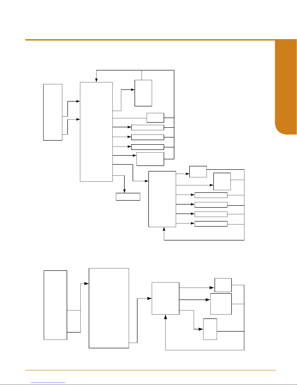
User’s Manual
238-741-00K
May 2019
3
THZ 3/ TDZ
Programmable Smart HART Temperature Transmitter
Figure 4.6. TDZ
Configure
Input Types
RJC Temp
Sensor 1
Sensor 2
3
or THZ
3
Sensor 1 and Sensor 2 menus in Input menu
degC
SX Meas ure Mode
S1 Input Type
Sensor 1 EGU
SX Br oken Wire Detecon
SX BW Holdoff Time
SX Running Average
SX 2Wir e Offset
SX Sensor Informaon
SX Scaling
SX Custom Curve*
See Figure 4.7
degF
degR
Kelv in
mV
ohm
%
Disabled
Enabled
Enter Holdoff Time
Enter SX Running Av er age
Enter SX 2Wire Offset
Sensor X USL
Sensor X LSL
Sensor X Min Span
Sensor X s/n
Sensor X Scl En
Sensor X EGU
Sensor X Input Min.
Sensor X Input Max.
Disabled
Enabled
Enter Sensor X Input Min.
Enter Sensor X Input Max.
inH2O
inHg
H2O
…..
SECTION 4
Figure 4.7. TDZ
Configure
Input Types
RJC Temp
Sensor 1
Sensor 2
3
or THZ
Sensor X Scal e Min.
Sensor X Scal e Max.
3
Custom Curve for Sensor 1 and Sensor 2 in Input menu
SX Meas ure Mode
S1 Input Type
Sensor 1 EGU
SX Br oken Wire Detecon
SX BW Holdoff Time
SX Running Average
SX 2Wir e Offset
SX Sensor In formaon
SX Scaling
SX Custom Curve*
Sensor X CC En
Sensor X EGU
Sensor X CC ID
Enter Sensor X Scale Min.
Enter Sensor X Scale Max.
Disabled
Enabled
inH2O
inHg
H2O
…..
CC 1
CC 2
CC 3
CC 4
- 61 -
www.miinet.comMoore Industries-International, Inc.
Page 62

3
THZ 3/ TDZ
Programmable Smart HART Temperature Transmitter
Ranging and Mapping:
The Ranging and Mapping menu will allow you to view current Device Variable assignment/
mapping to PV, SV, TV, and QV. It will also allow you to designate or change each one as
needed. To do so enter the Change Variable Mapping menu option. This menu will prompt
you to select from RJC Temperature, Sensor 1, Sensor 2, Backup 1-2, Backup 2-1,
Average, Dierential 1-2, Dierential 2-1, Absolute Dierential, Low Select, or High
Select to each variable (PV, SV, TV, & QV).
User’s Manual
238-741-00K
May 2019
SECTION 4
-Smart Range: Selecting this will prompt the menu shown in Figure 4.8. The
menu, displays the following information:
Min span, Sensor 1 EGU, PV LRV, and PV URV
to PV (PV is); that Sensor variable’s LSL (lower scale limit), USL (upper scale limit), Min Span
(minimum span), Sensor variable’s EGU, PV LRV (Primary variable lower range value), and the
PV URV (Primary variable upper range value).
Enter the desired 0% device variable value for the PV LRV, and this is the value will set
the Analog output at its 0% scale (normally is 4mA).
Enter the desired 100% device variable value for the PV URV, and this is the value will set
the Analog output at its 100% scale (normally is 20mA).
Any value which falls within the range of the mapped device variable LSL and USL may be
used for PV LRV and PV URV.
Note: After making all desired changes enter SEND to update the unit.
Figure 4.8. TDZ
Filter
PV Damp ing
Configure
Sensor
Ranging and
Mapping
3
3
or THZ
Ranging and Mapping within Input menu
Change Variable Mapping
Smart Range
PV is
Smart Range
PV is, Sensor 1 LSL, Sensor 1 USL, Sensor 1
. This displays which Sensor is mapped
PV
SV
Dv(x)
TV
QV
RJC Temper ature
Sensor 1
Sensor 2
Backup 1-2
Backup 2-1
Average
Differen al 1-2
Differen al 2-1
Absolu te Di ffere nal
Low Select
High Select
www.miinet.com Moore Industries-International, Inc.
SV is
TV is
QV is
Note:
Dv(x) = Device Variable
mapped to Dynamic Variable(s)
(PV, SV, TV, or QV)
i.e., If Sensor 1 is mapped to PV
then Sensor 1 will be displayed
within the Smart Range Menu
Dv(x)
Dv(x)
Dv(x)
- 62 -
PV is
Sensor 1 LSL
Sensor 1 USL
Sensor 1 Mi n span
Sensor 1 EGU
PV LRV
PV URV
Dv(x)
Dv(x) LS L
Dv(x) US L
Dv(x) Min span
Dv(x) EG U
PV URV
PV LRV
Ente r URV
Ente r LRV
Page 63

User’s Manual
238-741-00K
May 2019
3
THZ 3/ TDZ
Programmable Smart HART Temperature Transmitter
Dual Input:
The Dual Input menu will allow you to view and set Scaling and and Custom Curve for
the following Device Variables: Backup 1-2, Backup 2-1, Average, Dierential 1-2,
Dierential 2-1, Absolute Dierential, Low Select, and High Select. Refer to Figure 4.9
for clarication, menu is shown for Backup 1-2 but is the same for any of the given Device
variables.
Note: The
Note: After making all desired changes enter SEND to update the unit.
Figure 4.9. TDZ
Defaul t Confi g
Config Wi zards
Dual Input*
Anal og Ou tput
HART Sengs
System Config
Adva nce Sengs
Dual Input
Input
Display
3
or THZ
Differen al 1-2
Differen al 2-1
Absolute Differenal
menu is only visible if Advance Settings is Enabled.
3
Dual input
Backup 1-2
Backup 2-1
Av erage
Low Select
High Select
Backup 1-2
Backup 1-2 EGU
Scaling
Custom Curve
Backup 1-2 Sc l En
Backup 1-2 EGU
Backup 1-2 Inpu t Min
Backup 1-2 Inpu t Max
Backup 1-2 Sc ale Mi n
Backup 1-2 Sc ale Ma x
Disabled
Enabled
Enter Backup 1-2
Input Min
Enter Backup 1-2
Input Max
Enter Backup 1-2
Scale Min
Enter Backup 1-2
Scale Min
inH2O
inHg
H2O
…..
SECTION 4
All menus follow same
format as Backup 1-2
Select your Device Variable
and follow same flow.
Backup 1-2 CC En
Backup 1-2 EGU
Backup 1-2 CC ID
Disabled
Enabled
CC 1
CC 2
CC 3
CC 4
inH2O
inHg
H2O
…..
- 63 -
www.miinet.comMoore Industries-International, Inc.
Page 64

3
THZ 3/ TDZ
Programmable Smart HART Temperature Transmitter
Analog Output:
The Analog Output menu will allow you to view and set the following menu items: AO Zero,
AO Full, AO URV (Under range value), AO ORV (Over range value), Fail Mode, and AO
Fail to Value. See Figure 4.10 below for further clarication.
Note: After making all desired changes enter SEND to update the unit.
User’s Manual
238-741-00K
May 2019
SECTION 4
Figure 4.10. TDZ
Defaul t Confi g
Config Wi zards
Input
Dual Input*
Anal og Output
HART Sengs
Display
System Config
Adva nc e
Sengs
3
or THZ
3
Analog Output
Fail Mo de
AO Fail to Value
AO Zero
AO Full
AO URV
AO ORV
Enter AO Zero Value
Enter AO Full Value
Enter AO URV Value
Enter AO ORV Valu e
Enter AO Fail to Valu e
High
Low
Hold Last
Fail To Valu e
Enter
www.miinet.com Moore Industries-International, Inc.
- 64 -
Page 65

User’s Manual
238-741-00K
May 2019
3
THZ 3/ TDZ
Programmable Smart HART Temperature Transmitter
HART Settings:
The HART Settings menu
Long Tag, Descriptor, Message, Date, Final asmbly num, Dev id, Hardware rev and Burst
Configuration.
Poll Addr [0]– This is the HART Polling Address, enter a number from 0-63.
Num req preams [10]– This displays the number of Preamble Characters (0xFF) that are sent
before any HART requested message. This is set to 10.
Num resp preams (5-20) [5]– Enter the number of Preamble Characters (0xFF) that are
sent before any HART response message. This command selects the minimum number
of preambles to be sent by a device before the start of a response packet in the HART
message. A longer preamble means slower communication. The number of preambles
may need to be manually increased for some HART hosts, if there are missed messages
or communication errors.
Tag– Place a unique label that corresponds to your instruments location or specific usage
(8 characters maximum).
Long Tag– Place a unique label that corresponds to your instruments location or specific usage
(32 characters maximum).
Descriptor– Place text that is used as a description of how the instrument is being used (16
characters, maximum).
Message– Place additional information that may be helpful in describing the instrument or its
use (32 characters,maximum).
Date– Store a date that corresponds to specific system function, i.e. instrument configuration
date, calibration due date, preventive maintenance schedule, etc.
Final asmbly num [0]– You may enter a number that is used for identification purposes, and is
associated with the field device (8 characters, maximum).
Dev id– This is a read-only value that uniquely identifies the field device when combined with
the manufacturer identification and device type.
Hardware rev– This is a read-only value which corresponds to the revision of the electronics
hardware of the field device.
Burst Configuration– Burst Mode enables the device to continuously send out HART
messages to any listening device. This mode can be configured to send out up to 3
burst messages. See HART Burst Message description in the Feature Overiew at the
begiinning of Section 4 for more information.
See Figure 4.11 for further clarication.
displays the following options Poll Addr, Num req preams, Tag,
SECTION 4
Note: The Burst Configuration
Note: After making all desired changes enter SEND to update the unit.
menu is only visible if Advance Settings is Enabled.
- 65 -
www.miinet.comMoore Industries-International, Inc.
Page 66

3
THZ 3/ TDZ
Programmable Smart HART Temperature Transmitter
User’s Manual
238-741-00K
May 2019
Figure 4.11. TDZ
Defaul t Confi g
Config Wi zards
Input
Dual Input*
SECTION 4
Anal og Ou tput
HART Sengs
Display
System Config
Adva nce
Sengs
Note:
Enter Value that is within the range (LRV to URV) of
the device variable the user selected from the BMSg
Cmd. i.e: if cmd 1:PV is selected, and Sensor 1 is
mapped to PV, and Sensor 1 is RTD 3850, then the
value user can enter here is -200 to 850
3
or THZ
Num req preams
Num resp prea ms
Descriptor
Fina l asmbly nu m
Hardware rev
Burs t Configuraon *
3
HART Settings menu
Poll Addr
Displays Num req preams
Enter Num resp preams
Tag
Long Tag
Messag e
Date
Enter Final asmbly num
Dev id
Displays Hardware Rev
Burst Message 1
Burst Message 2
Burst Message 3
Enter Poll Addr
Enter Tag
Enter Long Tag
Enter Descriptor
Enter Message
Enter Date
Displays Dev id
Cmd 1: PV
Cmd 2: % range/Current
Cmd 3: Dyn vars/current
Cmd 9: Device vars w/ status
Cmd 33: Device variable s
Cmd 48: Read Addional Device Stat us
Wired HART Enabled
BMsg [x] Mode
BMsg [x] Cmd
BMsg [x] Update Per
BMsg [x] Max Update Per
BMsg [x] Trig Mode
BMsg [x] Trig Units
BMsg [x] Trig Level
Burst Variables
Off
CMD 9 & 33 only
Enter secs
Enter secs
Enter Value
Connuous
Window
Falling
On-change
inH2O
inHg
H2O
…..
Rising
1 BMsg [1][0]
2 BMsg [1][1]
3 BMsg [1][2]
4 BMsg [1][3]
5 BMsg [1][4]
6 BMsg [1][5]
7 BMsg [1][6]
8 BMsg [1][7]
RJC Temp
Sensor 1
Sensor 2
Backup 1-2
Backup 2-1
Average
Differen al 1- 2
Differen al 2- 1
Absolu te Diffe ren al
Low Select
High Select
www.miinet.com Moore Industries-International, Inc.
- 66 -
Page 67

User’s Manual
Defaul t Confi g
238-741-00K
May 2019
3
THZ 3/ TDZ
Programmable Smart HART Temperature Transmitter
Display Menu (TDZ3 only)
The Display menu allows you to select which variables are shown and also allows for custom
names and engineering units (EGU). Refer to Figure 4.12 for further clarication.
Note: The Configure Custom EGU*, and Configure Custom Name* menus are only visible if
Advance Settings is Enabled.
Note: After making all desired changes enter SEND to update the unit.
Note: Both the Custom EGU and Custom Name are limited to 5 alphanumeric characters.
Legal characters are:
A-Z (caps only)
0-9
% ` ( ) * + , - / < = > ? @ [ \ ] ^ _
Figure 4.12. TDZ
Config Wi zards
Input
Dual Input*
Anal og Ou tput
HART Sengs
Display
System Config
Adva nce
Sengs
RJC Temp Custom EGU En
Backup 1-2 Custom EGU En
Backup 2-1 Custom EGU En
Differen al 1-2 Custom EGU En
Differen al 1-2 Custom EGU
Differen al 2-1 Custom EGU En
Differen al 2-1 Custom EGU
Absolu te Di f...Custom EGU En
Absolu te Di f...Custom EGU
Low Select Cu stom EGU En
High Select Custom EGU En
3
or THZ
Configure Custom EGU*
Configure Custom Name*
RJC Temp Custom EGU
Sensor1 Custom EGU En
Sensor1 Custom EGU
Sensor2 Custom EGU En
Sensor2 Custom EGU
Backup 1-2 Custom EGU
Backup 2-1 Custom EGU
Average Custom EGU En
Average Custom EGU
Low Select Cu stom EGU
High Select Custom EGU
3
Display menu
Dyn Var Disp lay Flags
Decimal Places
Dev Var Displa y Flags
Note: Any 2, 3, 4
or all can be
selected to display
in scrolling
Disable/Enab le
Ente r EGU
Disable/Enab le
Ente r EGU
Disable/Enab le
Ente r EGU
Disable/Enab le
Ente r EGU
Disable/Enab le
Ente r EGU
Disable/Enab le
Ente r EGU
Disable/Enab le
Ente r EGU
Disable/Enab le
Ente r EGU
Disable/Enab le
Ente r EGU
Disable/Enab le
Ente r EGU
Disable/Enab le
Ente r EGU
PCT
AO
PV
SV
TV
QV
RJC Temp
Zero
One
Two
Three
Auto
RJC Temp Custom EGU En
Backup 1-2 Custom EGU En
Backup 2-1 Custom EGU En
Differen al 1-2 Custom EGU En
Differen al 1-2 Custom EGU
Differen al 2-1 Custom EGU En
Differen al 2-1 Custom EGU
Absolu te Di f...Custom EGU En
Absolu te Di f...Custom EGU
Low Select Cu stom EGU En
High Select Custom EGU En
Sensor1
Sensor2
Backup 1-2
Backup 2-1
Average
Differen al 1-2
Differen al 2-1
Absolu te Di f...
Low Select
High Select
RJC Temp Custom EGU
Sensor1 Custom EGU En
Sensor1 Custom EGU
Sensor2 Custom EGU En
Sensor2 Custom EGU
Backup 1-2 Custom EGU
Backup 2-1 Custom EGU
Average Custom EGU En
Average Custom EGU
Low Select Cu stom EGU
High Select Custom EGU
On
OFF
Disable/Enab le
Ente r EGU
Disable/Enab le
Ente r EGU
Disable/Enab le
Ente r EGU
Disable/Enab le
Ente r EGU
Disable/Enab le
Ente r EGU
Disable/Enab le
Ente r EGU
Disable/Enab le
Ente r EGU
Disable/Enab le
Ente r EGU
Disable/Enab le
Ente r EGU
Disable/Enab le
Ente r EGU
Disable/Enab le
Ente r EGU
SECTION 4
- 67 -
www.miinet.comMoore Industries-International, Inc.
Page 68

3
THZ 3/ TDZ
Programmable Smart HART Temperature Transmitter
Dynamic Variable Display Flags
These flags control which Dynamic Variables (PCT, AO, PV, SV, TV, QV) are displayed. By
default PV is shown.
When PV, SV, TV, or QV are selected for display, each will result in three screens.
123.45 / Dynamic Var Name
SECTION 4
123.45 / Source Device Var Name
123.45 / Units
For example: If the PV is 123.45 OHMS being sourced from the Average Device Variable, the
following will be shown:
123.45 / PV
123.45 / AVG
123.45 / OHMS
When the Percent of Range or Loop Current are selected for display, each will be shown using
two screens:
12.345 / AO
12.345 / MA
or
12.345 / PCT
12.345 / PCT
User’s Manual
238-741-00K
May 2019
If there is a problem with the underlying Device Variable, only one screen will be shown:
BADDQ / Dynamic Var Name
In this last case, the nature of the error will be shown separately.
Decimal Places [Auto]
This setting (0-3, AUTO) controls the maximum number of decimal places shown. For example, a
setting of AUTO, will display 1.2345, or 12.345. Depending on the magnitude of the whole portion
of the number, the decimal point may be forced to the right. If 3 Decimal places are selected,
1.234 will be shown. However the DP will be moved to allow 123.45 to be shown.
www.miinet.com Moore Industries-International, Inc.
- 68 -
Page 69

User’s Manual
238-741-00K
May 2019
3
THZ 3/ TDZ
Programmable Smart HART Temperature Transmitter
Device Variable Display Flags
These flags control if individual Device Variables are shown. One or all Device Variables can be
selected (SEN1, SEN2, RJC T, BU1-2, BU2-1, AVG, DIF12, DIF21, ABDIF, LOSEL, HISEL).
When selected, a Device Variable is shown using two screens.
123.45 / Name (default or custom name)
123.45 / UNITS
If there is a problem with the Device Variable, then the following will be shown:
BADDQ / Name (default or custom name)
Congure Custom EGU*
Each Device Variable can have a custom EGU string specified for it. The Custom EGU must be
enabled in Advanced Settings for it to be displayed. This is a 5 character custom string.
Legal characters are:
A-Z (caps only)
0-9
% ‘ ( ) * + , - / < = > ? @ [ \ ] ^ _
Congure Custom Name*
Each Device Variable can have a custom name string specified for it. The custom name must be
enabled in Advanced Settings for it to be displayed. This is a 5 character custom string.
SECTION 4
Legal characters are the same as those for custom EGU (see above)
For displayed Device Variables, the custom name will replace the default name.
Dynamic Variables cannot have a custom name. However when the underlying Device Variable’s
name is shown, the custom name is shown instead.
- 69 -
www.miinet.comMoore Industries-International, Inc.
Page 70

3
THZ 3/ TDZ
Programmable Smart HART Temperature Transmitter
System Configuration Menu
The System Cong menu
Alarms*.
Input Quality Alarms – Directs you to a sub-menu. When accessed, this will allow you turn
SECTION 4
Range Alarms – Directs you to a sub-menu. When accessed, you will able to congure Range
Each alarm has the following settings:
Enabled: [Disabled] Enables or Disables the Range Alarm
Source: [Primary Variable] The Variable to be used as a source for the Range Alarm
Response: [Warning] How to react if the specied condition occurs:
Assertion: [In Range] Indicates if the Range Alarm should detect if the source variable goes
Low: [0.00] The dened lower limit of the Range Alarm
High: [100.00] The dened upper limit of the Range Alarm
Latching: [Enabled] Disables or Enables latching of the alarm. Non-latching alarms return to a
On or O the following menu options Allow Measurement out of Conformance Range,
Allow Limited, and Allow Dropping. These settings allow the user to determine how
certain types of input quality issues are handled and how they can aect the Device
Variables, Dynamic Variables and AO. See Section 6 for more information.
Alarms 1-4. You can also select and reset an actively latched range alarm provided that
the input has returned to a non-alarm level. See Section 1 more information on Range
Alarms.
Warning - Sends a warning message to the HART Handheld/FDT host, TDZ3 display and
sets a HART status bit.
Alarm - Sends the AO into fail mode and sends an alarm message to the HART
Handheld/FDT host, TDZ3 display. It also sets a (dierent) HART status bit.
Out of range, or goes In range.
non-alarm state whenever the process input returns to a non-alarm level. Once tripped, a
latching alarm remains in an alarm state until the input returns to a non-alarm level and is
reset. Latching alarms can be reset from the Range Alarm or Custom Calibration menu.
displays the following options Input Quality Alarms and Range
User’s Manual
238-741-00K
May 2019
Note: The Range Alarms menu is only visible if Advance Settings is Enabled.
Note: If a Range Alarm Response is set to Alarm, the AO will always perform a fail response
even if the Source Device Variable is not assigned to the PV.
Note: After making all desired changes enter SEND to update the unit.
www.miinet.com Moore Industries-International, Inc.
- 70 -
Page 71
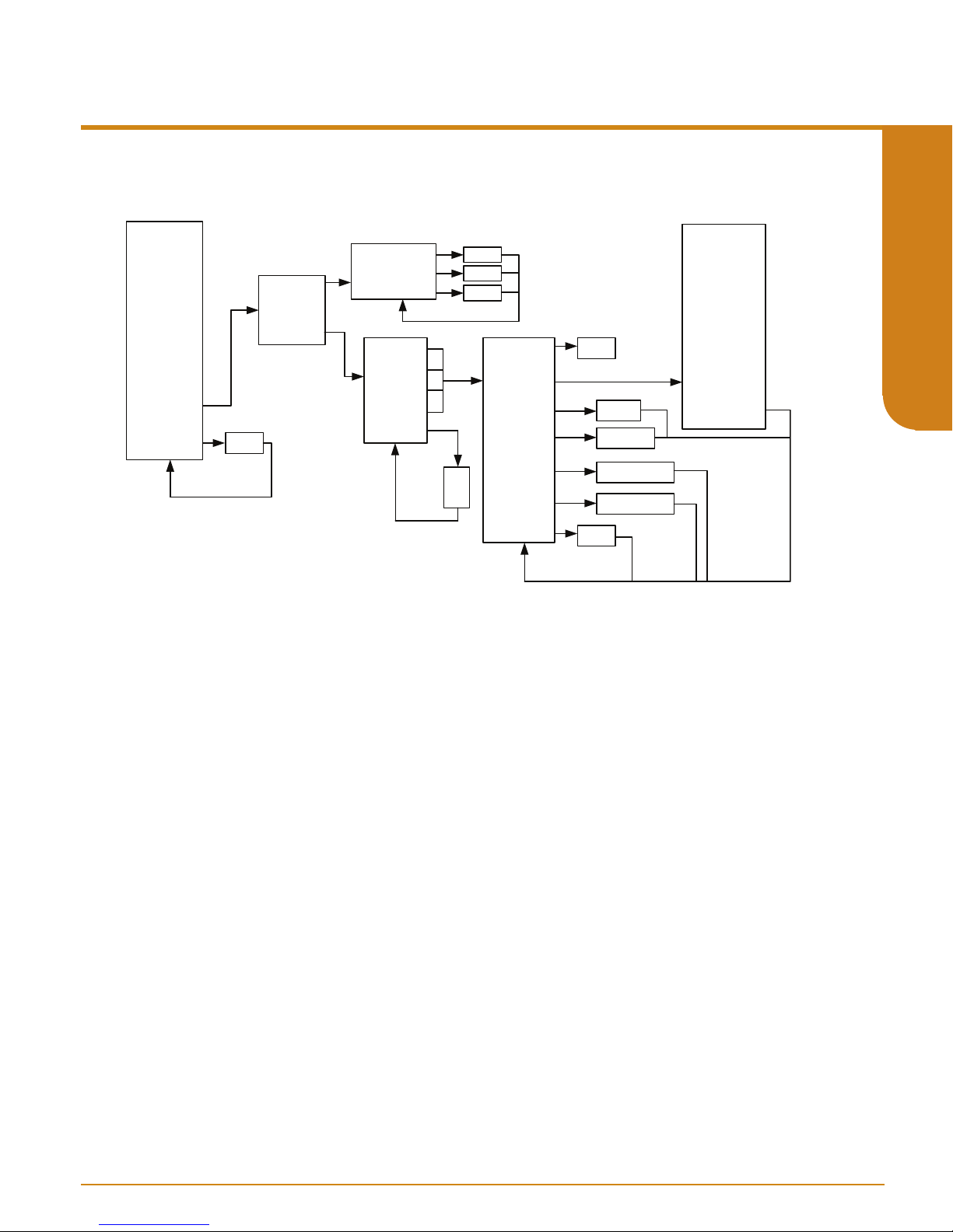
User’s Manual
Defaul t Confi g
238-741-00K
May 2019
3
THZ 3/ TDZ
Programmable Smart HART Temperature Transmitter
Figure 4.13. TDZ
Config Wi zards
Input
Dual Input*
Anal og Ou tput
HART Sengs
Display
System Config
Adva nce
Sengs
3
or THZ
Disable
Enable
3
System Configuration and Advance Settings Menus
Input Quality
Alar ms
Range
Alar ms*
Allow Meas out of Con
Allow Limited
Allow Dropping
Range Alarm 1
Range Alarm 2
Range Alarm 3
Range Alarm 4
Unlatc h RA
Range Alarm Selected
RA 1
RA 2
RA 3
RA 4
On/OFF
On/OFF
On/OFF
RA X Enable d
RA X Response
RA RA X can be any
RA X Sour ce
RA X Mode
RA X Low
RA X High
X Latching
Disable
Enable
Warnin g
Al arm
Out of range
In range
Enter Low Range
Enter Hi gh Range
Disable
Enable
RJC Temp
Sensor 1
Sensor 2
Backup 1-2
Backup 2-1
Average
Differen al 1-2
Differen al 2-1
Absolu te Di f...
Low Select
High Select
Percent of Range
PV Loop Cu rrent
PV
SV
TV
QV
SECTION 4
- 71 -
www.miinet.comMoore Industries-International, Inc.
Page 72
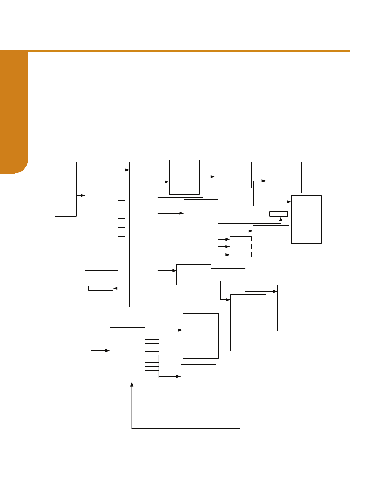
3
THZ 3/ TDZ
Programmable Smart HART Temperature Transmitter
Custom Calibration Menu
The Custom Calibration menu allows you to access the following menus: Status, Input
(PV) Capture, Variable Trim, AO Trim, AO Trim Reset, Loop Test, Input Simulation, S1
Corrosion Detection, S2 Corrosion Detection and Unlatch RA. Refer to Figure 4.14 below.
Status – Directs you to a sub-menu. When accessed, you will come to the following menu
options, System Status, Addl Status Bytes, Subsystem Status, Input Status, User Cfg
Status, and Dev Variable Status. Refer to Figure 4.14.
SECTION 4
Figure 4.14. TDZ
3
or THZ
3
Status menu within the Custom Calibration Menu
User’s Manual
238-741-00K
May 2019
Process
Vari ables
Setup
Custom
Calibraon
Review
Status
Input (PV) Capture
Vari able Trim
AO Trim
AO Trim Reset
Loop Te st
Input Simu laon
S1 Corrosion Det…
S2 Corrosion Det…
Unla tch RA*
See Figure 4.15
Syst em Stat us
Addl Stat us Byte s
Subsystem Stat us
User Cfg Status
Dev Var Status
DV Cf g Error Summ
RJC Temp Status
Sensor1Status
Sensor2Status
Backup 1-2 St atus
Backup 2-1 St atus
Average Stat us
Differenal 1-2 Stat us
Differenal 2-1 Stat us
Absolute Differenal
Low Sele ctStatus
High SelectStat us
Input Status
Sys Stat Summar y
In Errs and Warns
PV Status
SV St at us
TV Status
QV St at us
Ext dev status
Range Alarm Status
Ambient Temperat ure
Sensor 1 Trim St atus
Sensor 2 Trim St atus
User Configuraon
Analog Out put Stat us
RJC Temp Config
Sensor1 Config
Sensor2 Config
BU 1-2 Config
BU 2-1 Config
Average Config
Diff 1-2 Config
Diff 2-1 Config
Abs Diff Config
LOSEL Config
HISEL Config
BAD DQ
S1 BAD
S2 BAD
S1 LIMITED
S2 LIMITED
On Backup
Backup Sensor BAD
Cfg: S1 Unit s Wrong
Cfg: S2 Unit s Wrong
Cfg: My Out Units BAD
Cfg: S1 Disabled
Cfg: S2 Disabled
Cfg: CC Inject ID
Sensor Status 1
Sensor 1 St atus 1
Sensor 1 St atus 2
Sensor 2 St atus 1
Sensor 2 St atus 2
System Stat us Summary
Diagnosc Status
Input Error Summary
Input Warning
Summar y
Range Alarm Status
Same As S1
Same As S1
Same As S
Output Fixed
Output Sa turated
Low Saturaon
High Saturaon
Low Calibra on Error
High Calibraon Error
Curren t Calibraon E…
Voltage Calibraon…
Output Mode Config..
Fail Mode Config Error
URV/ORV Config Er ror
Zero /Full Config Erro r
Trim Er ror
Wrong Me asurement
Wrong Sensor
Measur ement Misma..
Wrong Mo de
Lower Unit Mismatch
Upper Limit Mismatch
Lower Point Limits
1
Upper Point Limits
Lower Value Limits
Upper Value Li mits
Upper Delta
Lower Delta
Span Value
Span Point
Broken RJC
ADC Sa turated
ADC Not Running
Bad Lead Res
Soware Sat
Bad Calib
Bad Config
Sensor Norm Fail
Trim Er ror
Term Temp Sensor C….
Sensor 1 Config
Sensor 2 Config
Analog Output Config
Label Config
HART Co nfig
User Misc Config
Custom Curve 1 Config
Custom Curve 2 Config
Custom Curve 3 Config
Custom Curve 4 Config
BW, Terminal 1
BW, Terminal 2
BW, Terminal 3
BW, Terminal 4
ADC Sa turated
ADC Not Runni ng
Bad Lead Res
Bad RJC Value
Soware Sat
Bad Calib
Bad Config
Sensor Norm Fail
www.miinet.com Moore Industries-International, Inc.
- 72 -
Page 73

User’s Manual
238-741-00K
May 2019
3
THZ 3/ TDZ
Programmable Smart HART Temperature Transmitter
Input Capture– Input Capture is used to match the device input and output zero and full scale
to a known value.
Adjust input sensor to 0% value to TDZ
will set the device’s output to known 4mA value. Adjust input sensor to 100% value to
TDZ3 or THZ3 and follow the screen instructions. This will set the device’s output to a
known 20mA value.
Variable Trim– This menu allows you to view the following options Device Variable Trim,
Device Variable Trim Reset, and Display Device Variable Trim. Refer to Figure 4.15.
AO Trim– Directs you to a sub-menu. Here you can select Reset Trim, Trim Zero or Trim Full.
AO Trim Reset– Directs you to a sub-menu. Here you can select No or Yes.
Loop Test– A loop test may be performed in order to check output performance and accuracy
and to trim other instruments in the loop. Your output will be a current value, in mA, equal
to the value you input. You can check the other current devices on the loop and calibrate
them to this signal.
Input Simulation – Allows you Clear or Set a simulated Input.
S1 Corrosion Detection – This captures the nominal resistance value of Sensor 1, then
allows setting 2 threshold resistances (warning and alarm) to identify when corrosion
occurs. This applies only to Thermocouples and 3W and 4W RTDs. See section 1 for
more information on Corrosion Detection.
S2 Corrosion Detection – This captures the nominal resistance value of Sensor 2, then allows
setting 2 threshold resistances (warning and alarm) to identify when corrosion occurs.
This applies only to Thermocouples and 3W and 4W RTDs. See section 1 for more
information on Corrosion Detection.
Unlatch Range Alarm– This allows you to select and reset an actively latched range alarm
(1-4) provided that the input has returned to a non-alarm level.
3
or THZ3 and follow the screen instructions. This
SECTION 4
Note: The Unlatch RA* menus are only visible if Advance Settings is Enabled.
Note: After making all desired changes enter SEND to update the unit.
- 73 -
www.miinet.comMoore Industries-International, Inc.
Page 74

3
THZ 3/ TDZ
Programmable Smart HART Temperature Transmitter
User’s Manual
238-741-00K
May 2019
Figure 4.15. TDZ
Calibration Menu
Process
Vari ables
Setup
Custom
Calibraon
Input (PV) Capture
SECTION 4
Review
S1 Corrosi on Det…
S2 Corrosi on Det…
3
or THZ
AO Trim Reset
Input Simu laon
3
Status
Vari able Trim
AO Trim
Loop Test
Unla tch RA*
Input (PV), Variable Trim, AO Trim, AO Trim Reset, and Loop Test within the Custom
LRV
URV
Device Va ri able Trim
Device Va ri able Trim Reset
Display De vice Variab le Trim
Trim Zero
Trim Zero
No
Yes
See Figure 4.16
4mA
20mA
Other
End
Sensor1
Sensor2
Sensor1
Sensor2
Enter mA
Sensor1
Sensor2
Figure 4.16. TDZ
3
or THZ
3
Input Simulation, S1 Corrosion Detection, S2 Corrosion Detection and Unlatch Range
Alarms within the Custom Calibration Menu
Process
Variables
Setup
Custom
Calibraon
Review
Input (PV) Capture
S1 Corrosi on Det…
S2 Corrosi on Det…
Status
Variable Trim
AO Trim
AO Trim Reset
Loop Test
Input Simu laon
Unla tch RA*
RJC Temp
Sensor 1
Sensor 2
Backup 1-2
Backup 2-1
Average
Differen al 1-2
Differen al 2-1
Absolute Di ffere nal
Low Select
High Select
Sx Corr De tecon
RA1
RA2
RA3
RA4
Disable
Enable
Clear
Set
Enter Value
S1 Corr Detecon
S1 Corr Re s
S1 Corr Wa rn Level
S1 Corr Er ror Leve l
S1 Corr Ba se Re s
Capture Base Value
Disable
Enable
Current Valu e
Enter Value
Enter Value
Captured Valu e
YES
NO
www.miinet.com Moore Industries-International, Inc.
- 74 -
Page 75

User’s Manual
238-741-00K
May 2019
3
THZ 3/ TDZ
Programmable Smart HART Temperature Transmitter
Section 5 -
Conguration using FDT/DTM
Software
Before reading this section on the FDT/DTM conguration, please read the Conguration
Overview at the beginning of Section 4 for general information on conguring the TDZ
This section provides information on conguring the TDZ
(an FDT frame application). For users who already have an FDT Frame Application, all the
following information is still relevant except for the PACTware installation. For more information
on FDT/DTM please refer to www.fdtgroup.org.
3/
THZ3 using a PC with PACTware
FDT Frame Application
Moore Industries has always provided manufacturer-specic programs to operate our eld
instruments to the full extent. TDZ
allows conguration and adjustment of any and all eld instruments ,which have a DTM. For
users who do not already have an FDT frame application, Moore Industries provides PACTware.
An FDT frame application, such as PACTware, is a PC program which interfaces with individual
software modules for instrument operation. This interface is regarded as the FDT; the individual
software modules for instrument adjustment are called DTMs (Device Type Manager) . This
conguration makes user-friendly adjustments possible because the interface for instrument
adjustment is optimally adapted to each instrument.
3/
3
THZ
will require the use of an FDT frame application, which
3/
THZ3.
SECTION 5
Furthermore, you can communicate with an FDT frame application not only via HART but also
via any standard eld bus system. Moore Industries provides a proprietary serial communication
DTM named MISP, which allows faster device conguration using our USB communication
cable. The MISP DTM will be provided in addition to the TDZ
frame application, these individual instrument DTMs and communication DTMs are installed as
required.
3/
3
THZ
Device DTM. In the FDT
FDT/DTM Software Installation
In order to get started you will need to either install the PACTware software and DTMs or just
install the DTMs (if you already have an FDT frame application installed). All the les you need
can be found on our website www.miinet.com.
- 75 -
www.miinet.comMoore Industries-International, Inc.
Page 76

3
THZ 3/ TDZ
Programmable Smart HART Temperature Transmitter
The PACTware installer le will install PACTware and all required DTMs.
PACTware_vxxx_FDT_DTM_Installation_Moore_Industries.exe
When you run the installer you will have the option to select which components you want to
install:
PACTware 4.1 SP3
SECTION 5
ICS Generic HART FDT DTM - This is for HART instruments which do not have a DTM
HART Communication FDT DTM - This is for using a HART modem to connect to TDZ
MII MISP Communications DTM - This is for using a Moore Industries serial or USB cable
MII TDZ3 THZ3 DTM - This is the Device DTM for the TDZ3 and THZ
User’s Manual
238-741-00K
May 2019
3
/THZ3
3
You will also nd individual DTM installers on the website and Moore Tools CD in Comms and
Device folders. Use these if you already have PACTware or another FDT frame application and
just need to install or update the Moore Industries DTMs.
DTM Comms Folder: MISP_vxxx_CommsDTM_Moore_Industries.exe
THZ3 TDZ3 Conguration Tools Folder:TDZ3_THZ3_vxxx_DeviceDTM_Moore_Industries.exe
www.miinet.com Moore Industries-International, Inc.
- 76 -
Page 77

User’s Manual
238-741-00K
May 2019
3
THZ 3/ TDZ
Programmable Smart HART Temperature Transmitter
The USB cable driver is also available in the Comms folder on the CD if you need to install the
Moore Industries USB cable on your PC for the rst time.
USB Cable Utility Software Folder: MIIUSBCable_vxxx_PC_Conguration_Software_Moore_
Industries.exe
Moore Industries MISP DTM Installation
3/
If you want to communicate with the TDZ
will need to install the MISP DTM. The MISP DTM can be found on the Moore Industries
Conguration Tools CD, or from our website www.miinet.com.
File is named: MISP_DTM_Conguration_Software_Moore_Industries.exe
To install simply locate le, double click le and follow on screen instructions to install.
3
THZ
using the USB communications cable, you
SECTION 5
Moore Industries “THZ3/TDZ
File is named: THZ3_TDZ3_PC_Conguration_Software_Moore_Industries
To install simply locate le, double click le and follow on screen instructions to install.
3
” DTM Installation
- 77 -
www.miinet.comMoore Industries-International, Inc.
Page 78

3
R
THZ 3/ TDZ
Programmable Smart HART Temperature Transmitter
Using DTM’s with FDT Frame Application (PACTware)
Once you have installed all the necessary DTMs on your system, you are now ready to launch
the FDT frame application (PACTware) and congure your device. There are two distinct
communications methods you can choose to use. Refer to Figures 5.1-5.3 for hookup diagrams
for these congurations.
HART Communications DTM: is a Communication DTM for use of HART devices via HART
modem.
SECTION 5
MISP Communications DTM: is a Moore Industries Serial Protocol which allows communication
via Fuse-Protected USB Communications cable (P/N: 804-030-26).
User’s Manual
238-741-00K
May 2019
Figure 5.1. THZ
Figure 5.2. TDZ
3
HPP hook-up diagram for HART or MISP DTM configurations.
Load=250 ohms
–
12-24Vdc
Power
+
Supply
To COM Port
of THZ3
HART Held
Communicator
or
HART Modem
connects to
Serial/USB
COM Port of PC
3
HP hook-up diagram for HART or MISP DTM configurations.
HART Modem
OR
MISP
PC
Current Meter
Moore Indusries
P/N: 804-030-26
To USB
Port of PC
Current Meter
–
ADDRADD
TDZ
+
–
Voltage
+
Source
3
Load=250 ohms
–
12-24Vdc
Power
+
Supply
HART Held
Communicator
or
HART Modem
connects to
Serial/USB
COM Port of PC
www.miinet.com Moore Industries-International, Inc.
–
HART Modem
OR
MISP
PC
- 78 -
+
To COM Port
3
of TDZ
Moore Indusries
P/N: 804-030-26
To USB
Port of PC
–
+
Voltage
Source
Page 79

User’s Manual
238-741-00K
May 2019
3
THZ 3/ TDZ
Programmable Smart HART Temperature Transmitter
Figure 5.3. THZ
3
DIN hook-up diagram for HART or MISP DTM configurations.
–
Voltage
+
Source
Current Meter
+
–
HART Modem
OR
MISP
PC
To COM Port
of THZ3
Moore Indusries
P/N: 804-030-26
To USB
Port of PC
12-24Vdc
Power
Supply
HART Held
Communicator
HART Modem
connects to
Serial/USB
COM Port of PC
Load= 250 ohms
–
+
or
DUAL SENSOR
SMART HART
TEMPERATURE
TRANSMITTER
SECTION 5
- 79 -
www.miinet.comMoore Industries-International, Inc.
Page 80

3
THZ 3/ TDZ
Programmable Smart HART Temperature Transmitter
Connecting to THZ3/TDZ3 using MISP
To congure the MISP Communications DTM you will need to add necessary DTMs within the
PACTware software to start your conguration. You will also need to have a Moore Industries
Fuse Protected USB Communications Cable (sold separately P/N:804-030-26). Refer to Fuse
Protected USB Communications Cable documentation for installation of USB Communications
Utility and conguration. Follow steps below to connect and conguration your device.
3/
1. Connect TDZ
SECTION 5
2. Launch PACTware software.
3. Right Click on the Device Tag named “HOST PC” and select “Add device”
Figure 5.4. MII MISP configuration adding a device.
3
THZ
unit per Figures 5.1- 5.3.
User’s Manual
238-741-00K
May 2019
4. Select the MISP Communications DTM and enter OK.
Figure 5.5. Adding the MII MISP Communication DTM.
www.miinet.com Moore Industries-International, Inc.
- 80 -
Page 81

User’s Manual
238-741-00K
May 2019
3
THZ 3/ TDZ
Programmable Smart HART Temperature Transmitter
5. Right Click on COM1 and select “Parameter”.
Figure 5.6. Adding the MII MISP Communication DTM.
6. In the Communications Port drop-down menu select the actual COM port which your Fuse
Protected USB Communications Cable is connected to click “Apply” then “Ok”.
Note: You need to be certain to click apply when making these changes. Once the correct
COM Port is selected and you have applied it to parameters the small Pencil icon will disappear.
If Pencil icon is still visible, it indicates that the change has not been applied to device.
SECTION 5
Figure 5.7. Selecting correct COM port for the MII MISP Communication DTM.
- 81 -
www.miinet.comMoore Industries-International, Inc.
Page 82

3
THZ 3/ TDZ
Programmable Smart HART Temperature Transmitter
7. Return to Device Tag Menu the MISP COM port you selected should now appear i.e.
“MISP:COM12” hover over it, right click and select “Connect”. You will now see the “online state”
turn green to indicate you have a connection.
Figure 5.8. COM Port Confirmation
SECTION 5
User’s Manual
238-741-00K
May 2019
8. Next you will right click on “MISP:COM 12” and select “Add device”. Select desired
TDZ3/ THZ
Figure 5.9. Adding Device to MISP:COM Port
Figure 5.10. Selecting desired THZ3/ TDZ3 DTM
3
DTM from list and click “Ok”. See Figures 5.9 and 5.10.
www.miinet.com Moore Industries-International, Inc.
- 82 -
Page 83

User’s Manual
238-741-00K
May 2019
3
THZ 3/ TDZ
Programmable Smart HART Temperature Transmitter
9. Now right click on selected DTM (i.e. TDZ
You will now see the “online state” turn green to indicate you have a connection.
Figure 5.11. Connecting to selected Device DTM for THZ 3 / TDZ
10. Right click on DTM (i.e. TDZ3 [HP]) in the Device Tag menu and select “Parameters”. This
will bring up screen for the TDZ
the device. You may also acquire the factory default settings directly form device by right clicking
on DTM (i.e. TDZ
Figure 5.12. Enabling Parameters Configuration page for THZ3/TDZ3 DTM
3
[HP]) in the Device Tag menu and selecting “Load from device”.
3
parameters. You are now ready to start your conguration of
3
[HP]) in the Device Tag menu and select “Connect”.
3
SECTION 5
11. You will now see the “online state” turn green to indicate you have a connection. Now you
can go ahead and congure parameters of the DTM (i.e. TDZ3 [HP]) .
3
Figure 5.13. THZ
/ TDZ 3 Parameters
Please go to THZ3/TDZ3 DTM Conguration section
- 83 -
www.miinet.comMoore Industries-International, Inc.
Page 84

3
THZ 3/ TDZ
Programmable Smart HART Temperature Transmitter
Connecting to THZ3/TDZ3 using HART
To congure the HART Communications DTM you will need to add necessary DTMs within the
FDT frame application (PACTware) software to start your conguration. Follow steps below to
achieve this.
3
3
/THZ
1. Connect TDZ
2. Launch FDT frame application (PACTware) software.
SECTION 5
Figure 5.14. HART configuration adding a device.
unit per Figures 5.1- 5.3.
User’s Manual
238-741-00K
May 2019
3. Right Click on the Device Tag named “HOST PC” and select “Add device”
Figure 5.15. Adding HART Communication DTM.
www.miinet.com Moore Industries-International, Inc.
- 84 -
Page 85

User’s Manual
238-741-00K
May 2019
3
THZ 3/ TDZ
Programmable Smart HART Temperature Transmitter
4. Select the HART Communications DTM and enter OK
Figure 5.16. COM Port Parameters
5. Right Click on COM1 and select “Parameter”.
Figure 5.17. Selecting COM Port Parameters
SECTION 5
- 85 -
www.miinet.comMoore Industries-International, Inc.
Page 86

3
THZ 3/ TDZ
Programmable Smart HART Temperature Transmitter
6. In the Serial Interface drop-down menu select the actual COM port which your HART Modem
is connected to click “Ok” to apply.
Figure 5.18. COM Port Confirmation
SECTION 5
7. Return to Device Tag Menu the COM port you selected should now appear i.e. “COM11” hover
over it, right click and select “Connect”. You will now see the “online state” turn green to indicate
you have a connection.
Figure 5.19. Adding Device to COM Port
User’s Manual
238-741-00K
May 2019
8. Next you will right click on “COM11” and select “Add device”. Select desired “TDZ
DTM and click “Ok”.
Figure 5.20. Selecting desired Device DTM for THZ 3/ TDZ
www.miinet.com Moore Industries-International, Inc.
3
- 86 -
3/
THZ
3
”
Page 87

User’s Manual
238-741-00K
May 2019
3
THZ 3/ TDZ
Programmable Smart HART Temperature Transmitter
9. Now right click on selected DTM (i.e. TDZ
You will now see the “online state” turn green to indicate you have a connection.
Figure 5.21. Connecting Device DTM for THZ 3 / TDZ
10. Right click on “right click on selected DTM (i.e. TDZ
“Parameters”. This will bring up screen for the DTM parameters. You are now ready to start your
conguration of the device. You may also acquire the factory default settings directly form device
by right clicking on selected DTM (i.e. TDZ
from device”.
Figure 5.22. Enabling Parameters for selected THZ3 / TDZ3 DTM
3
[HP]) the Device Tag menu and select “Connect”.
3
3
[HP]) in the Device Tag menu and select
3
[HP]) in the Device Tag menu and selecting “Load
SECTION 5
11. You will now see the “online state” turn green to indicate you have a connection. Now you
can go ahead and congure parameters of the on selected DTM (i.e. TDZ3 [HP]).
3
Figure 5.23. THZ
/ TDZ 3 Parameters
- 87 -
www.miinet.comMoore Industries-International, Inc.
Page 88

3
THZ 3/ TDZ
Programmable Smart HART Temperature Transmitter
THZ3/TDZ3 conguration using DTM
The following menu options and terminology are specic to PACTware but other FDT frame
applications have similar menus. This PACTware menu is common for all device DTMs and
only the ‘Additional Functions’ submenu has
out this feature is not available for the
Figure 5.24. Menu Options for THZ 3 / TDZ 3 DTM
SECTION 5
TDZ
3/
THZ3.
TDZ
3/
3
THZ
specics. Where the menu is grayed
User’s Manual
238-741-00K
May 2019
Right click on selected
Connect – Select this to connect to device you wish to configure.
Disconnect – Select to disconnect from current device connected.
Load from device – Select this to load configuration currently on device to PACTware.
Store to Device – Select this to send current configuration from PACTware to device.
Parameter – Select this to enter and configure the device (You can also configure the device by double
clicking on the device icon with the left mouse button).
Measured Value – Select this to view the device values for the Dynamic Variables and Device Variables.
Simulation – N/A.
Diagnosis – Select this to view Main System Status, within this you can find Additional Status Bytes and
Subsystem Status .
Additional Functions – Selecting this opens a submenu:
Compare Oine: N/A
Compare Online: N/A
Set Value: N/A
Set HART Polling Address: N/A
Clear Conguration Changed Bit: This clears the Configuration changed Bit by HART master.
This feature only works when using HART Communications.
Clear More Status Available Bit: Clears the More Status available Bit when Main Systems Status indicates
“More Status Available”.
Upload Custom Curves From Device: This will upload any or all of custom curves available to PACTware.
Download Custom Curves To Device: This will download any or all of custom curves available to Device.
Import Custom Curves: This will import any Custom Curves settings external files using the .CVS Format to
PACTware.
Export Custom Curves: This will allows you to export and save .CVS Format files of any Custom Curves
settings generated in PACTware.
Write device data to le: N/A.
Add Device – N/A.
Exchange Device – Select this if you wish to swap devices.
Delete Device –
disconnected.
Properties – Select this to view the “About DTM” and “History” .
Select this to delete the current device, PACTware will not allow you to delete device unless device is
3/
TDZ
THZ3 DTM icon to display the following menu:
www.miinet.com Moore Industries-International, Inc.
- 88 -
Page 89

User’s Manual
238-741-00K
May 2019
3
THZ 3/ TDZ
Programmable Smart HART Temperature Transmitter
THZ3/TDZ3 DTM Parameter Reference guide
The following provides a comprehensive list of DTM conguration menus and options which can
be used as a quick reference guide to identify the dierent conguration capabilities and locate
them in the menu system. For more information on the specic features please refer to the
Conguration Overview and the specic menu descriptions.
Note:
* Is used to identify advanced features which are only accessible using Advanced Setup
menus in the DTM.
THZ3/TDZ3 Parameter
Input
Congure Sensor
*RJC Temp – change engineering units (EGU)
Sensor 1/2
-Input & Type (eg. Thermocouple TypeK, 4W RTD Pt3850 100ohm etc.)
-EGU (engineering units)
-Broken Wire detection & hold o
-Running Average lter
-2-Wire oset (2W RTD/resistance only)
-*Corrosion detection (enable, base, warning and failure settings)
-Serial Number
-Filter – 50Hz or 60Hz input lter to reduce mains induced noise
*Sensor 1/2 Scaling
*Sensor 1/2 Custom Curve enable & selection
SECTION 5
Ranging & Mapping
Primary Variable
-PV (Analog Output Source) selection
-Smart Range –sets the PV Zero and Full values to AO 0-100%
-PV Damping – set delay in the response to stop input noise from generating output errors
SV, TV & QV Mapping- assigns the Device Variables (eg. SEN1, BU1-2)
*Congure Dual Input
*Scaling settings and Custom Curve selection for all the calculated Device Variables
*System Conguration
*High Availability (Input Quality Alarms) setup
Allow Measurement Out of Conformance Range
Allow Limited
Allow Dropping
*Custom Curves – import/input 1-4 custom curves
*Range Alarms – congure up to 4 range alarms
- 89 -
www.miinet.comMoore Industries-International, Inc.
Page 90

3
THZ 3/ TDZ
Programmable Smart HART Temperature Transmitter
Analog Output
PV input range (display only)
AO Zero & Full Values
AO Under Range & Over Range Values
AO Fail Mode (High, Low, Hold Last, Fail to Value)
User’s Manual
238-741-00K
May 2019
Display (TDZ
Select Dynamic & Device Variables to be displayed
SECTION 5
Number of Decimal Places
*Congure Custom EGU & Custom Name
HART Settings
Allows conguration of HART parameters:
Polling Address
Number of HART response preamble characters
Tag, Long Tag, Descriptor, Message, Final assembly number
Programmed Date, Device id, Hardware revision, HART Revision, Firmware revision (Read only)
*Burst Conguration - can be congured to send out up to 3 burst messages
Custom Calibration
Input (PV) Capture - match the device input and output zero and full scale to a known value.
Sensor 1/2 Trim
Analog Output Loop Test & Trim
Input Simulation - Clear or Set a simulated Input.
*Sensor 1/2 Corrosion Detection base value capture and monitor
3
only)
www.miinet.com Moore Industries-International, Inc.
- 90 -
Page 91

User’s Manual
238-741-00K
May 2019
3
THZ 3/ TDZ
Programmable Smart HART Temperature Transmitter
THZ3/TDZ3 DTM Parameter in Basic Setup Configuration
Once you have added and connected the DTM’s within PACTware, you are now ready to make
the conguration changes to device parameters that best t your needs. There are 2 views of
the conguration, Basic and Advanced. By default you will be shown the Basic Setup which will
provide conguration for most applications.
If you need to congure the advanced features, then you will need to select the Advanced
Setup menu by clicking on the Advanced Setup icon on the bottom left of the window. To view
Advanced Setup features and functions see the TDZ
Conguration later in this Section.
Note: The Advanced Setup menu contains all the Basic Setup plus the advanced features so
the following Basic Setup description is applicable to Advanced Setup also.
Figure 5.25. THZ 3 / TDZ 3 Parameters Page Menu for Basic Setup
3/
THZ3
DTM Parameter Advanced Setup
SECTION 5
Parameter Menu Configuration
The Parameter Menu page consists of ve main Menu options Input, Analog Output, Display,
HART Settings, and Custom Calibration.
Note: The Display option will only be active for the TDZ 3. It will be grayed out for the THZ
- 91 -
3
www.miinet.comMoore Industries-International, Inc.
Page 92

3
THZ 3/ TDZ
Programmable Smart HART Temperature Transmitter
INPUT
Configure Sensor Types:
Select the Congure Sensors this will enable to congure Sensor 1 and Sensor 2 as follows:
Refer to Figure 5.26.
Sensor 1 INPUT and Type Selection:
-Resistance:
SECTION 5
3. Sensor 2 can also be configured in the same manner.
1. From the Input Drop-down Menu select either 2 Wire Resistance, 3 Wire
Resistance, or 4 Wire Resistance Connection.
2. From the Type Drop-down Menu Select a Resistance value from 4k, 2k, 1k, 500, 250,
or 125 ohms.
3. Sensor 2 can also be configured in the same manner.
-mV:
1. From the Input Drop-down Menu select Millivolts.
2. From the Type Drop-down Menu choose from 1k, 500, 250, 125, 62.5, or 31.25 mV
3. Sensor 2 can also be configured in the same manner.
-Potentiometer:
1. From the Input Drop-down Menu select Potentiometer.
2. From the Type Drop-down Menu select either 4k, 2k, 1k, 500, 250, or 125 ohms
3. Sensor 2 can also be configured in the same manner.
-RTD:
1. From the Input Drop-down Menu select either 2 Wire, 3 Wire, or 4 Wire Connection
Configuration.
2. From the Type Drop-down Menu select desired RTD.
4. Sensor 2 can also be configured in the same manner.
-T/C:
1. From the Input Drop-down Menu select either Thermocouple (with RJC), or
Thermocouple (no RJC). Select TC (no RJC) ONLY if you are using a rare and old
remote reference junction wiring strategy.
2. From the Type Drop-down Menu select desired T/C.
User’s Manual
238-741-00K
May 2019
Sensor 2 INPUT and Type Selection:
1. You can choose to have Sensor 2 in “Not Used” mode and the parameters will be
greyed out. You also can congure Sensor 2 in the same manner as Sensor 1.
Note: While the THZ3/TDZ3 will accept a dual input sensor configuration the following
limitations apply only when using two input sensors:
TDZ 3 [HP] 2-wire and/or 3-wire sensors. 4-wire sensors (RTDs) cannot be used.
THZ3 [DIN] (see figure 3.2) - 2-wire and/or 3-wire sensors. 4-wire sensors (RTDs) cannot be
used.
www.miinet.com Moore Industries-International, Inc.
- 92 -
Page 93

User’s Manual
238-741-00K
May 2019
3
THZ 3/ TDZ
Programmable Smart HART Temperature Transmitter
THZ3 [HPP] (see figure 3.4) – Sensor 1 can be configured as 2-wire or 3-wire sensor. Sensor 2
is then restricted to a 2-wire sensor.
Sensor 1 and 2 Engineering Units:
Figure 5.26. THZ 3 / TDZ 3 Parameters Input Configure Sensor Types
SECTION 5
1. From the Engineering Units Drop-down Menu select the unit of measurement
desired.
Sensor 1 and 2 Broken Wire Detection:
1. From the Broken Wire Detection Drop-down Menu select either Enable or Disabled.
Sensor 1 and 2 Broken Wire Holdoff (0.0-60.0secs): This allows users to add an additional
time delay before broken wire is detected. When enabled, a Broken Wire delay of 0-60 seconds
can be set which provides some noise immunity and prevents false alarms caused by other
factors that may be misinterpreted as Broken Wire.
1. Enter the Broken Wire Holdoff value you desire.
Sensor 1 and 2 Running Average Filter Setting (1-16) : This function is for filtering the input
signal. The TDZ3 and THZ3 has a running average filter with a user-selected range between 1
and 16.
1. Enter the Running Average Filter Setting value you desire.
Note: A higher Running Average Filter setting provides smoother output transitions; however,
increases response time. Conversely, a lower setting provides a faster response time, but may
seem more unstable.
- 93 -
www.miinet.comMoore Industries-International, Inc.
Page 94

3
THZ 3/ TDZ
Programmable Smart HART Temperature Transmitter
Sensor 1 and 2 Two Wire Offset (0.0-250.0) : This setting is to offset the wire resistance of the
2-Wire sensor cable, and will help the accuracy of the measurement.
1. Enter the Offset value you desire.
Sensor 1 and 2 Serial Number:
1. Enter the Serial Number for the device here.
User’s Manual
238-741-00K
May 2019
SECTION 5
Filter: This setting is used to configure the input filter. The filter is designed to reduce the effects
of mains induced noise. The input filter frequency value should be set to the frequency of the
local AC supply–either 50Hz or 60Hz.
1. Choose either 50Hz or 60Hz filter for your the devices here.
Ranging and Mapping
The Ranging and Mapping menu will allow you to view current Device Variable assignment/
mapping to PV, SV, TV, and QV. It will also allow you to designate or change each one as
needed. To do so enter the Change Variable Mapping menu option. In this menu you will
select from RJC Temperature, Sensor 1, Sensor 2, Backup 1-2, Backup 2-1, Average,
Dierential 1-2, Dierential 2-1, Absolute Dierential, Low Select, or High Select to
each variable (PV, SV, TV, & QV).
In addition to mapping the Dynamic Variables, you can also set the PV lower range and upper
range values to AO 0-100% and PV Damping. PV Damping allows you to introduce a delay into
the response of your unit in order to stop short-lived spikes from initiating faults and generating
fault messages. The damping time setting is the time PV takes to make a 63% change in
response to a step change.
Figure 5.27. THZ 3 / TDZ 3 Parameters Input Ranging and Mapping
Refer to Figure 5.27.
www.miinet.com Moore Industries-International, Inc.
- 94 -
Page 95

User’s Manual
238-741-00K
May 2019
3
THZ 3/ TDZ
Programmable Smart HART Temperature Transmitter
Analog Output
The Analog Output menu will allow you to view and set Fail Mode type and Fail Mode
value you can see the following menu items: AO Zero, AO Full, AO URV, AO ORV, AO Fail
Mode, and AO Fail to Value. See Figure 5.28 below for further clarication.
Use this portion of the menu to set the AO Zero, AO Full, AO URV (under range value), AO
ORV (over range value), AO Fail MODE and AO Fail Mode values, to trim the output and to
reset the trimmed output.
Figure 5.28. THZ 3 / TDZ 3 Parameters Analog Output
SECTION 5
- 95 -
www.miinet.comMoore Industries-International, Inc.
Page 96

3
THZ 3/ TDZ
Programmable Smart HART Temperature Transmitter
User’s Manual
238-741-00K
May 2019
Display Menu (TDZ
The Display menu allows you to select which variables are shown and also allows for custom
names and engineering units (EGU). Refer to Figure 5.29 for further clarication.
Figure 5.29. TDZ 3 Display Menu Parameters Analog Output
SECTION 5
3
only)
When PV, SV, TV, or QV are selected for display, each will result in three screens.
123.45 / Dynamic Var Name
123.45 / Source Device Var Name
123.45 / Units
When the Percent of Range or Loop Current are selected for display, each will be shown
using two screens:
12.345 / AO
12.345 / MA
or
12.345 / PCT
12.345 / PCT
When selected, a Device Variable is shown using two screens.
123.45 / Name (default or custom name)
123.45 / UNITS
If there is a problem with the underlying Device Variable, only one screen will be shown:
BADDQ / Dynamic Var Name
In this last case, the nature of the error will be shown separately.
www.miinet.com Moore Industries-International, Inc.
- 96 -
Page 97

User’s Manual
238-741-00K
May 2019
3
THZ 3/ TDZ
Programmable Smart HART Temperature Transmitter
HART Settings
The HART Settings menu provides access to the following HART settings:
See Figure 5.30 for further clarication.
Poll Address (0-63) [0] – This is the HART Polling Address, enter a number from 0-63.
Number of Response Preambles (5-20) [5]– Enter the number of Preamble Characters
(0xFF) that are sent before any HART response message. This command selects the
minimum number of preambles to be sent by a device before the start of a response
packet in the HART message. A longer preamble means slower communication. The
number of preambles may need to be manually increased for some HART hosts, if there
are missed messages or communication errors.
Tag– Place a unique label that corresponds to your instruments location or specific usage
(8 characters maximum).
Long Tag– Place a unique label that corresponds to your instruments location or specific usage
(32 characters maximum).
Descriptor– Place text that is used as a description of how the instrument is being used (16
characters, maximum).
Message– Place additional information that may be helpful in describing the instrument or its
use (32 characters,maximum).
SECTION 5
Final Assembly Number [0] – You may enter a number that is used for identification purposes,
and is associated with the field device (8 characters, maximum).
Programmed Date– This is a read-only value, displays the date this unit was programmed at
factory.
Device Id (S/N)– This is a read-only value that uniquely identifies the field device when
combined with the manufacturer identification and device type.
Hardware Revision– This is a read-only value corresponds to the revision of the electronics
hardware of the field device.
HART Revision– This is a read-only corresponds to the HART revision installed on field device.
Firmware Revision– This is a read-only value corresponds to the revision of the Firmware of
the field device.
- 97 -
www.miinet.comMoore Industries-International, Inc.
Page 98

3
THZ 3/ TDZ
Programmable Smart HART Temperature Transmitter
Figure 5.30. THZ 3 / TDZ 3 HART Setting
SECTION 5
User’s Manual
238-741-00K
May 2019
www.miinet.com Moore Industries-International, Inc.
- 98 -
Page 99

User’s Manual
238-741-00K
May 2019
3
THZ 3/ TDZ
Programmable Smart HART Temperature Transmitter
Custom Calibration
The Custom Calibration menu
Sensor 1 Trim, Sensor 2 Trim, AO Loop Current Test/Trim, and Input Simulation.
Figure 5.31.
Figure 5.31. THZ 3 / TDZ 3 Custom Calibration Menu
Input (PV) Capture
Input Capture is used to capture the actual device input zero and full scale. Use the “PV Capture
Lower” or “PV Capture Upper” button to achieve this. Menu displays values for the following PV
Device Variable, PV Lower Limit, PV Upper Limit, PV Lower Range Value, PV Upper Range
Value, PV, and PV Status. See Figure 5.32
Figure 5.32. THZ
3
/ TDZ 3 Custom Calibration Menu - Input (PV) Capture
displays the following Sub menus options Input (PV) Capture,
See
SECTION 5
- 99 -
www.miinet.comMoore Industries-International, Inc.
Page 100

3
THZ 3/ TDZ
Programmable Smart HART Temperature Transmitter
Sensor 1 Trim
Here you can select your Trim Mode, select from either Disabled, One Point, or Two Point.
Also displayed are the following Values : Minimum Lower Trim Value, Maximum Lower
Trim Value, Minimum Upper Trim Value, Maximum Upper Trim Value, Minimum Span,
Sensor 1 Reading, Sensor 1 Reading (State), and Desired Trim Point Value. There are
three buttons Trim Lower Point, Trim Upper Point, and Factory Default. Finally a display
eld for the displaying Trim Result value. Refer to Figure 5.33.
User’s Manual
238-741-00K
May 2019
SECTION 5
Sensor 2 Trim
Is identical to the Sensor 1 Trim menu when Sensor 2 is enabled.
Figure 5.33. THZ 3 / TDZ 3 Custom Calibration Menu - Sensor 1 and Sensor 2 Trim
www.miinet.com Moore Industries-International, Inc.
- 100 -
 Loading...