


May 2016
178-722-00 D
Programmable Field-Mount
Loop Display (NEMA 4X, IP66)
SPD
Programmable Field-Mount
Loop Display (NEMA 4X, IP66)
SPD

Table of Contents
SPD Quickstart Menu ........................................................................................ 4
The SPD
.............................................................................................................. 5
About this Manual ................................................................................................................5
Specifications .................................................................................................... 6
Installing the SPD
Mounting .................................................................................................................................................... 7
Loop Connections ...................................................................................................................................... 7
Configuration Connections ........................................................................................................................ 7
.............................................................................................. 7
PC Configuration Software ............................................................................. 11
Programming the SPD
Site-Programming the SPD ................................................................................................12
PC-Programming the SPD
Installing the PC Configuration Software ................................................................................................. 13
Downloading the Configuration ............................................................................................................... 13
Programming the Input & Output .......................................................................................14
Input Settings ........................................................................................................................................... 14
.................................................................................... 12
.................................................................................................13
Display Settings ....................................................................................................................................... 14
Ta g ........................................................................................................................................................... 14
EGU ......................................................................................................................................................... 14
Linearization Mode .................................................................................................................................. 14
Filter ......................................................................................................................................................... 14
Display Resolution ................................................................................................................................... 14
Damping Time ......................................................................................................................................... 14
Continued on next page...

Table of Contents
(Continued)
Programming the Alarms Function (Only for units with the -2PRG Option) .......................15
Alarm Settings & Terms ........................................................................................................................... 15
Fail High/Low & Failsafe/Non-Failsafe ..................................................................................................... 15
Delay........................................................................................................................................................ 15
Capture Trip Point
.................................................................................................................................... 15
Programming the Trimming Parameters .............................................................................15
Programming with a Custom Curve
Linearization Data .................................................................................................................................... 16
Linearization Mode .................................................................................................................................. 16
Input Settings ........................................................................................................................................... 16
Display Settings ....................................................................................................................................... 16
...................................................................................16
Programming the SPD with a Square Root Table ..............................................................17
Option One: Generating a Custom Square Root Curve ......................................................................... 17
Option Two: Importing a Pre-made Square Root Curve ......................................................................... 17
Importing a Custom Curve Table ........................................................................................18
Exporting a Custom Curve Table
.......................................................................................18
Dimensions ...................................................................................................... 19
SPD Security
Customer Service
.................................................................................................... 20
............................................................................................ 20

ENTER
PASS
Enter the password
code to enable
settings changes.
Configure Options:
Engineering Unit
50/60Hz Filter
Damping Time
Decimal Point
Linear/Custom Mode
Applying the Input:
Match the displayed input to the
monitored sensor's output by
capturing the zero and full values.
Scaling the Display:
Custom-scale the display.
Scaling the Input:
Set the values to be displayed
at zero and full scale values
without calibration equipment.
Password Jumper
installed in OFF position.
Password Jumper
installed in ON position.
VIEW current settings
Front Panel
Push Buttons
SELECT
Use or push buttons to scroll
through menus and sub-menus.
Use SELECT push button to access
menu and/or make a choice.
VIEW
MENU
CONFG
OPTNS
SCALE
INPUT
APPLY
INPUT
TRIM
INPUT
SCALE
DSPLY
CONFG
ALARM
PASS
WORD
EXIT
CONFG
Configure Alarm:
Trip Point
Deadband
Trip Delay
High or Low Alarm
Failsafe or Non-Failsafe
Password:
View or change password
in SPD memory.
Configure Exit:
Exit the configuration menus and
return to real-time display of
selected process variable.
SELECT
Trimming the Input:
Trim the input to cause the SPD zero
and full values to read 4mA and 20mA,
respectively, even if the monitored sensor's
actual range is different.
SPD Quickstart Menu
SPD
Programmable Field-Mount
Loop Display (NEMA 4X, IP66)
The SPD
4-20mA LOOP INPUT
A1
SELECT
SITE PROGRAMMABLE
DISPLAY
ALARM RELAY #1
ALARM RELAY #2
PUSH-BUTTONS
FOR ON-SITE
CONFIGURATION
SPD
A2
(ALARM RELAYS
ARE OPTIONAL)
TO SERIAL
(COM) PORT
OF PC
OR
To USB
(COM)
Port of PC
803-040-26 FOR NON-ISOLATED CABLE
803-039-26 FOR ISOLATED CABLE
or Optional USB Cable Part# 208-236-00A*
*
When using Optional USB
Cable Part# 208-236-00
please assure that the ground
of the SPD is at the same
potential as the PC that the
usb cable is plugged in.
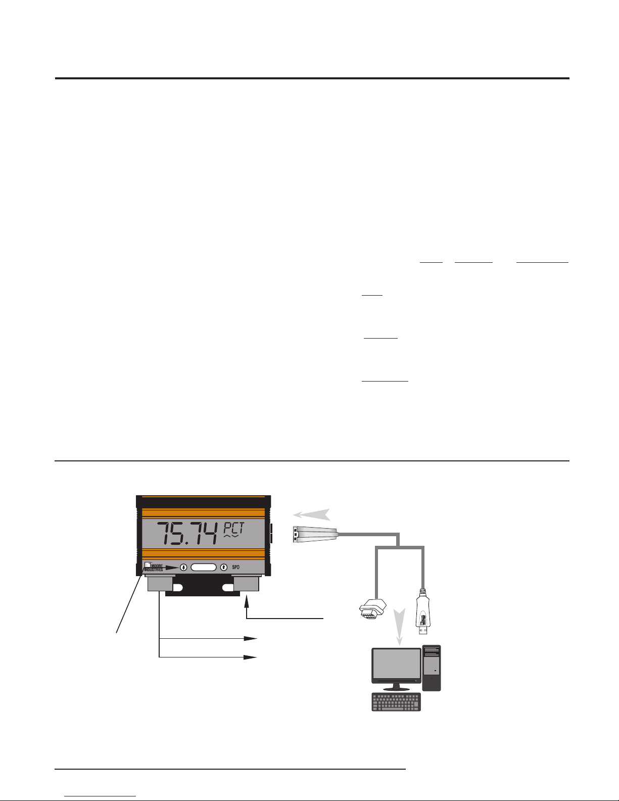
The Moore Industries universal SPD Programmable
Loop Display accepts a 4-20mA input from a process
transmitter or similar analog device, and indicates
real-time process status in mA, percent, or any
designated engineering unit (EGU) on its 5-digit
display. Both the process value and engineering unit
(up to 5 characters) are shown on the display.
Versatile Programmability—The SPD can be
programmed on-site using front mounted buttons, or
our easy-to-use SPD PC Configuration Software.
Extra-Large Display—Read the process status from
across the room using the SPD’s independently
configured display, which features 29 millimeter-high
(1.15 inch) characters and an optional back-lit display
(The –BL option requires a 24Vdc power supply).
Dual Alarm Relays Available—The SPD is available
with individually configurable dual alarm trip relays
(–2PRG option). Each relay can be set to trip if the
4-20mA process variable falls outside of user set
high and/or low process limits. This allows the SPD
to connect to a warning light, annunciator, bell, or
shutdown system, protecting your process with a
simple, reliable shutdown system.
About this Manual
Wherever you see a “Note”, “Caution”, or “WARNING
” pay particular attention.
• A“Note” provides information to help you in avoiding
minor inconveniences during calibration, installation,
or operation of the SPD.
• A “Caution” provides information on steps to take
in avoiding procedures and practices that could risk
damage to the SPD or other equipment.
Superior Accuracy—The SPD displays your process
information with phenomenal accuracy of ±0.012% of
input scale.
• A“WARNING ” provides information on steps to take
in avoiding procedures and practices that could pose
safety risks to personnel.
Housing—The SPD comes in our Field Housing (FH)
that is NEMA 4X and IP66 certified. Pipe-mount
hardware is optional.
Figure 1. Both PC- and Site-Programmable, the SPD accepts a 4-20mA signal and outputs the signal to two alarm relays
Demand Moore Reliability 5

SPD
Programmable Field-Mount
Loop Display (NEMA 4X, IP66)
Specifications
Display
Performance
Type: LCD; Top Row,
29.21mm (1.15 inch) high
black digits on a reflective
background; Bottom Row,
15.24mm (0.6 inch) high
black digits on a reflective
background
Format:
alphanumeric characters
plus sign and decimal point;
Bottom row is five
alphanumeric characters
Range:
Display Update Rate:
100msec
Minimum Display Span:
1.00
Accuracy: ±0.012% of
input scale at 22°C (72°F).
This includes the combined
effects of linearity,
hysteresis, repeatability,
and adjustment resolution. It
does not include ambient
temperature effect
Stability:
0.09% of span for 1 year;
0.16% of span for 3 years;
0.2% of span for 5 years
Resolution:
0.0028% of input scale
Power Consumption
(24DC power):
With 2PRG option, 0.65W;
With 2PRG and BL
options, 1.15W
Burden (on input loop):
2.3VLP model, 115Ω; 24DC
model, 20Ω
Top Row is five
-99999 to 99999
Performance
(Continued)
Over-Current
Protection:
absolute maximum
Display Input Overrange:
24mA
Digital Input Filter: User-
programmable;
50 or 60Hz
Minimum Input Signal:
3.8mA
Isolation:
When 24Vdc power supply
is used, 500V between
supply and input
Response Time: Normal
Linearization Mode:
180msec or less for input to
display on a step input from
10% to 90% of the input
scale, 220msec or less for
input to alarm from time
of step change on input to
alarm state when alarm is
set to trip mid-point;
Custom Linearization Mode:
200msec or less for input to
display on a step input from
10% to 90% of the input
scale, 400msec or less for
input to alarm from time
of step change on input to
alarm state when alarm is
set to trip mid-point
Damping: User-selectable
for 0-30 seconds
100mA
Ambient
Conditions
Weight
Operating Range:
-40°C to +85°C
(-40°F to +185°F)
Some slowing of display
response time will occur
below -25°C (-13°F)
Storage Range:
-45°C to +85°C
(-49°F to 185°F)
Relative Humidity:
0-95%, non-condensing
Ambient Temperature
Effect: ±0.005% of
span/°C maximum
RFI/EMI Immunity:
20V/m when tested
according to SAMA 33.1
ABC with 0.5% of span or
less error. 20 V/m@
80-1000MHz, 1 KHz AM,
when tested according to
IEC1000-4-3-1995
Common Mode Rejection:
100dB @ 50/60Hz
Normal Mode
Rejection: 50dB @
50/60Hz, 10mA p-p
maximum
1.56 kg (3.44 lbs.)
Specifications and information subject to change without notice.
6 Demand Moore Reliability

SPD
Programmable Field-Mount
Loop Display (NEMA 4X, IP66)
Installing the SPD
Installing the SPD in your loop involves mounting and
making the electrical connections. It is recommended
that the SPD be installed in the loop before it is
programmed so that you can use the input capture
features to capture the exact full and zero values of the
loop. (See Loop Connections) If this is not practical,
you can also use a variable current source and an
ammeter or multimeter to setup your unit before you
install it on the loop. (See Configuration Connections)
Mounting
The SPD comes prepared for field-mounting in a FH
enclosure.
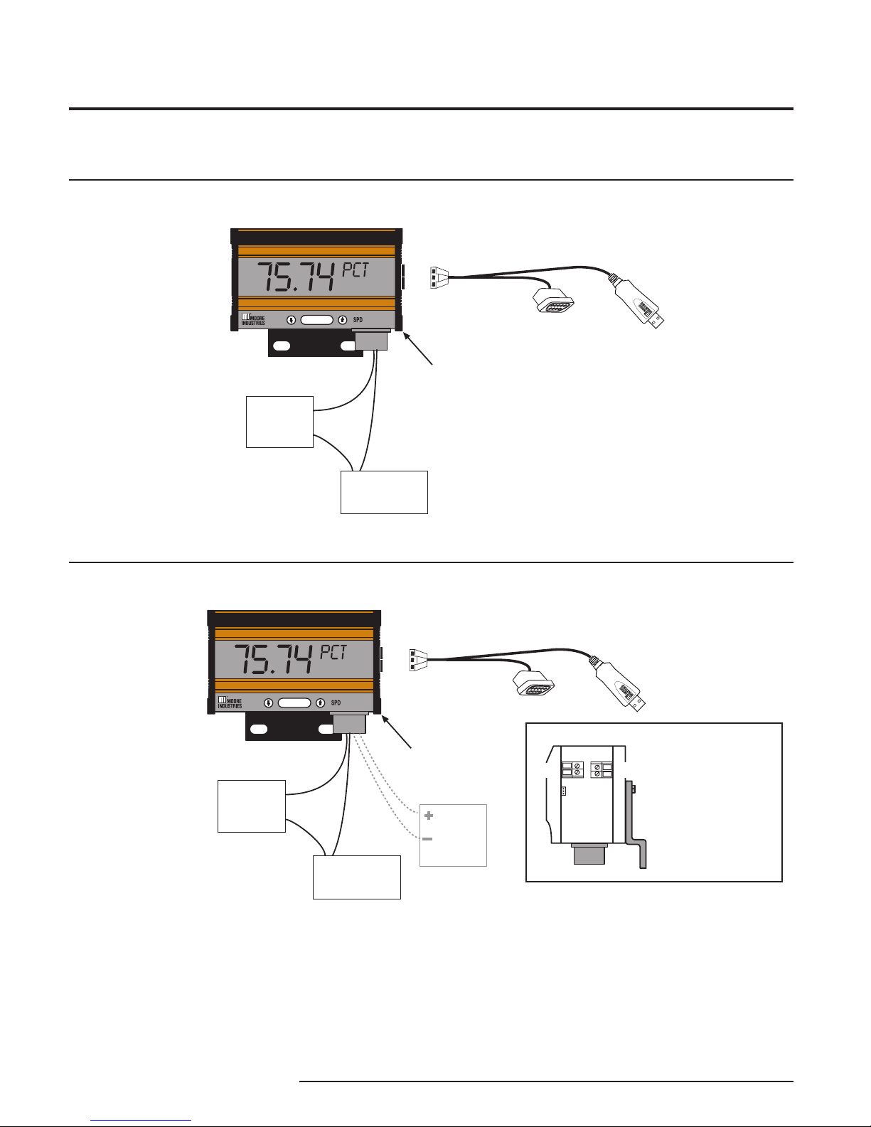
Loop Connections
The recommended method of programming requires
you to install the SPD into the loop before you program
it. Figures 2 and 3 describe typical loop installations
of the 2.3VLP and 24DC SPD units.
To connect to the SPD, you will first need to remove
the side panel(s). Use a flathead screwdriver to
remove the four screws on the right side of the SPD. If
your SPD has the –2PRG option, you will also need to
remove the left side panel to give access to the alarm
relays.
Once the panels are open, make the electrical
connections as shown in Figures 2 and 3. When
connecting the SPD to the PC, it is essential that you
use the communications cable included with your SPD.
Note that 2.3VLP models with the –BL option require a
24Vdc power supply to power the backlight.
Note:
On the tag for the communications cable, it should
read “rev. D” or later. If it does not list a revision, then
it is an older Moore Industries cable, and may or may
not work properly with the SPD.
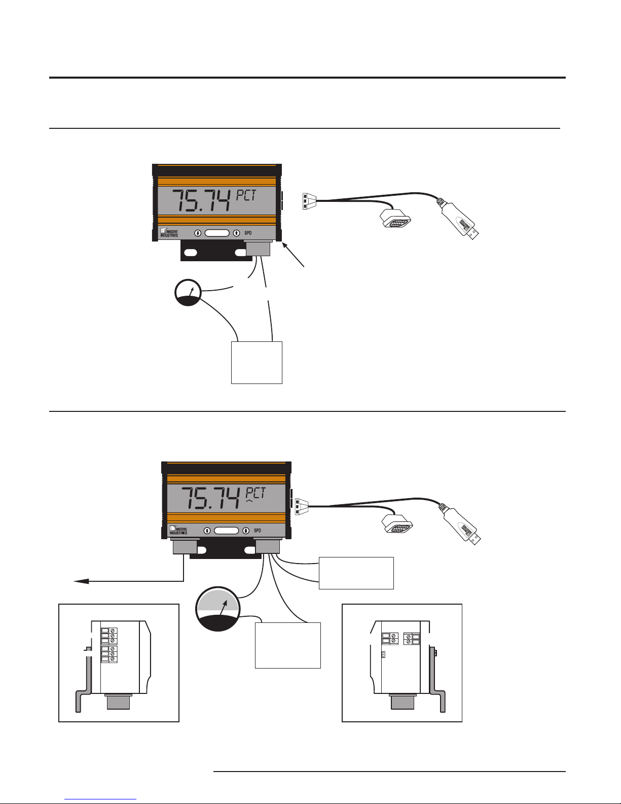
Configuration Connections
To configure the SPD before attaching it to the loop,
you need a calibrated, adjustable current source
capable of discrete output levels in the 4-20mA range.
It should have a minimum accuracy of ±0.01%. Once
you have the required equipment (as shown in
Table 1), hook up the SPD according to either
Figure 4 or 5.
To connect to the SPD, you will first need to remove
the side panel(s). Use a flathead screwdriver to
remove the four screws on the right side of the SPD.
If your SPD has the –2PRG option, you may decide to
remove the left side panel to give access to the alarm
relays.
Once the panels are open, make the electrical
connections as shown in the appropriate Figure. When
connecting the SPD to the PC, it is essential that you
use the communications cable included with your SPD.
Note that 2.3VLP models with the –BL option require a
24Vdc power supply to power the backlight.
Table 1. Assembling the Necessary Equipment
Device
Current Source
Power Supply
Multimeter
Communications
Cable
Screwdriver
Screwdriver
Adjustable, Accurate to ±0.01% of reading
24Vdc (24DC or –BL models only)
Accurate to ±0.025% of reading
Isolated and non-isolated versions available
Slotted Tip, head width 5mm, maximum
Large, slotted tip
Specifications
Demand Moore Reliability 7
SPD
Programmable Field-Mount
Loop Display (NEMA 4X, IP66)
SPD (2.3VLP Model)
SELECT
SITE PROGRAMMABLE
DISPLAY
REMOVE
PANEL
TO ACCESS
TERMINALS
CAUTION:
DO NOT CONNECT THE
LOOP POWER SUPPLY
DIRECTLY TO THE INPUT!
A CURRENT LIMITING
DEVICE SUCH AS A
TRANSMITTER MUST BE
IN THE LOOP!
TO SERIAL
(COM) PORT
OF PC
OR
To USB
(COM)
Port of PC
803-040-26 FOR NON-ISOLATED CABLE
803-039-26 FOR ISOLATED CABLE
or Optional USB Cable Part# 804-030-26*
*
When using Optional USB
Cable Part# 804-030-26
please assure that the ground
of the SPD is at the same
potential as the PC that the
usb cable is plugged in.
4-20mA
TRANSMITTER
–
+IN
–IN
+
–
LOOP
POWER
SUPPLY
SPD (2.3VLP Model)
SELECT
SITE PROGRAMMABLE
DISPLAY
+IN
–IN
+24VDC
COM
INTERNAL SIDE VIEW
REMOVE
PANEL
TO ACCESS
TERMINALS
NOTE:
FOR 2-WIRE UNITS WITH
THE BACKLIGHT (–BL)
OPTION, ALSO AT TACH A
24VDC POWER SUPPLY
TO THE TERMINALS
LABELED "BACKLIGHT".
PC COMM.
CABLE
4-20mA
ONLY
BACKLIGHT
ONLY
+
–
24VDC
POWER
SUPPLY
FOR -BL
OPTION
CAUTION:
DO NOT CONNECT THE
LOOP POWER SUPPLY
DIRECTLY TO THE INPUT!
A CURRENT LIMITING
DEVICE SUCH AS A
TRANSMITTER MUST BE
IN THE LOOP!
TO SERIAL
(COM) PORT
OF PC
OR
To USB
(COM)
Port of PC
803-040-26 FOR NON-ISOLATED CABLE
803-039-26 FOR ISOLATED CABLE
or Optional USB Cable Part# 804-030-26*
*
When using Optional USB
Cable Part# 804-030-26
please assure that the ground
of the SPD is at the same
potential as the PC that the
usb cable is plugged in.
4-20mA
TRANSMITTER
–
+IN
–IN
+
–
LOOP
POWER
SUPPLY
Figure 2-A. Loop Connections for the 2.3VLP SPD
Figure 2-B. Loop Connections for the 2.3VLP SPD with Backlight ( -BL option)
8 Demand Moore Reliability

SPD
Programmable Field-Mount
Loop Display (NEMA 4X, IP66)
SPD (2.3VLP Model)
SELECT
SITE PROGRAMMABLE
DISPLAY
INTERNAL SIDE VIEW
REMOVE
PANELS
TO ACCESS
TERMINALS
BACKLIGHT
ONLY
+
–
24VDC
POWER SUPPLY
FOR -BL
OPTION*
CAUTION:
DO NOT CONNECT THE
LOOP POWER SUPPLY
DIRECTLY TO THE INPUT!
A CURRENT LIMITING
DEVICE SUCH AS A
TRANSMITTER MUST BE
IN THE LOOP!
TO SERIAL
(COM) PORT
OF PC
OR
To USB
(COM)
Port of PC
803-040-26 FOR NON-ISOLATED CABLE
803-039-26 FOR ISOLATED CABLE
or Optional USB Cable Part# 804-030-26*
*
When using Optional USB
Cable Part# 804-030-26
please assure that the ground
of the SPD is at the same
potential as the PC that the
usb cable is plugged in.
*
For -ISC Option wiring for
Back light is located on left side,
remove panels to access terminals.
-ISC option has second port which
Back Light must be run through
Refer to Drawing 100-100-66
4-20mA
TRANSMITTER
–
+IN
–IN
+
–
LOOP
POWER
SUPPLY
Figure 2-C. Loop Connections for the 2.3VLP SPD with Backlight and Intrinsically Safe option ( -BL and -ISC )
SPD (24DC Model)
4-20mA
TRANSMITTER
+
–
CAUTION:
DO NOT CONNECT THE
LOOP POWER SUPPLY
TO THE SPD INPUT!
A CURRENT LIMITING
DEVICE SUCH AS A
TRANSMITTER MUST BE
IN THE LOOP!
A1
SELECT
SITE PROGRAMMABLE
DISPLAY
+IN
–IN
24DC POWER
SUPPLY
+
–
TO ALARM RELAYS
(UNITS WITH –2PRG)
+IN
–IN
+24VDC
COM
INTERNAL RIGHT SIDE VIEW
PC COMM.
CABLE
4-20mA
ONLY
POWER
+24VDC
COM
+
–
LOOP
POWER
SUPPLY
NO1
COM1
NC1
INTERNAL LEFT SIDE VIEW
RELAY 1
RELAY 2
NO2
COM2
NC2
TO SERIAL
(COM) PORT
OF PC
OR
To USB
(COM)
Port of PC
803-040-26 FOR NON-ISOLATED CABLE
803-039-26 FOR ISOLATED CABLE
or Optional USB Cable Part# 804-030-26*
*
When using Optional USB
Cable Part# 804-030-26
please assure that the ground
of the SPD is at the same
potential as the PC that the
usb cable is plugged in.
Figure 3. Loop Connections for the 24DC SPD
Demand Moore Reliability 9
SPD
Programmable Field-Mount
Loop Display (NEMA 4X, IP66)
SPD (24DC Model)
+
–
CAUTION:
DO NOT CONNECT THE
LOOP POWER SUPPLY
TO THE SPD INPUT!
A CURRENT LIMITING
DEVICE SUCH AS A
TRANSMITTER MUST BE
IN THE LOOP!
A1
SELECT
SITE PROGRAMMABLE
DISPLAY
+IN
–IN
24DC POWER
SUPPLY
+
–
TO ALARM RELAYS
(UNITS WITH –2PRG)
+IN
–IN
+24VDC
COM
INTERNAL RIGHT SIDE VIEW
PC COMM.
CABLE
4-20mA
ONLY
POWER
+24VDC
COM
NO1
COM1
NC1
INTERNAL LEFT SIDE VIEW
RELAY 1
RELAY 2
NO2
COM2
NC2
AMMETER OR
MULTIMETER
+
–
ADJUSTABLE
CURRENT
SOURCE
TO SERIAL
(COM) PORT
OF PC
OR
To USB
(COM)
Port of PC
803-040-26 FOR NON-ISOLATED CABLE
803-039-26 FOR ISOLATED CABLE
or Optional USB Cable Part# 804-030-26*
*
When using Optional USB
Cable Part# 804-030-26
please assure that the ground
of the SPD is at the same
potential as the PC that the
usb cable is plugged in.
SPD (2.3VLP Model)
SELECT
SITE PROGRAMMABLE
DISPLAY
+
–
REMOVE
PANEL
TO ACCESS
TERMINALS
NOTE:
SEE FIGURES 2-B AND 2-C FOR
24VDC CONNECTIONS FOR
BACKLIGHT ( -BL )
AMMETER OR
MULTIMETER
+
–
ADJUSTABLE
CURRENT
SOURCE
CAUTION:
DO NOT CONNECT THE
LOOP POWER SUPPLY
DIRECTLY TO THE INPUT!
A CURRENT LIMITING
DEVICE SUCH AS A
TRANSMITTER MUST BE
IN THE LOOP!
TO SERIAL
(COM) PORT
OF PC
OR
To USB
(COM)
Port of PC
803-040-26 FOR NON-ISOLATED CABLE
803-039-26 FOR ISOLATED CABLE
or Optional USB Cable Part# 804-030-26*
*
When using Optional USB
Cable Part# 804-030-26
please assure that the ground
of the SPD is at the same
potential as the PC that the
usb cable is plugged in.
–IN
+IN
Figure 4. Configuration Connections for the 2.3VLP SPD
Figure 5. Configuration Connections for the 24DC SPD
10 Demand Moore Reliability

SPD
Programmable Field-Mount
Loop Display (NEMA 4X, IP66)
Figure 6. All of the SPD Operating Parameters can be set from the Main Screen of the Configuration Program.
4
3
2
1
7
6
5
PC Configuration Software
The SPD PC Configuration Software can be used to
program all of the SPD’s parameters. For detailed
information on how to use our configuration software,
access our HelpMap Navigation System.
The PC Software is made up of these sections:
1. Arrow Buttons–Three Arrows here are used for
Downloading to Unit (down Arrow), Uploading from
Unit (Up Arrow),or Get Set-up (Right Arrow).
After uploading file (by pressing the Up Arrow), you
must press the Right Arrow button to populate all
information into the configuration dialog area.
2. Status & Process Variables–The Status portion
of the screen displays the activity of the
connected unit. It will show you if the unit is
Idle, Uploading, Downloading, or Monitoring.
Process Variables lists the value of the SPD’s
Input and Display.
Note:
3. Input Settings, Display Settings, & Device–
Displays the current configuration of the SPD.
4. Connection–The Connection box displays the
status of the SPD’s communication with the PC
Program.
5.
Input/Range/Output/Trimming/Custom Curve–
These sections allow you to set the desired
configuration for the SPD.
Ta g–Allows you to assign an identifying phrase to
6.
an individual SPD.
7. EGU, Linearization Mode, Filter, Display
Resolution, & Damping Time–These sections
allow you to configure the selected value for the
SPD.
Demand Moore Reliability 11
SPD
Programmable Field-Mount
Loop Display (NEMA 4X, IP66)
ENTER
PASS
Enter the password
code to enable
settings changes.
Configure Options:
Engineering Unit
50/60Hz Filter
Damping Time
Decimal Point
Linear/Custom Mode
Applying the Input:
Match the displayed input to the
monitored sensor's output by
capturing the zero and full values.
Scaling the Display:
Custom-scale the display.
Scaling the Input:
Set the values to be displayed
at zero and full scale values
without calibration equipment.
Password Jumper
installed in OFF position.
Password Jumper
installed in ON position.
VIEW current settings
Front Panel
Push Buttons
SELECT
Use or push buttons to scroll
through menus and sub-menus.
Use SELECT push button to access
menu and/or make a choice.
VIEW
MENU
CONFG
OPTNS
SCALE
INPUT
APPLY
INPUT
TRIM
INPUT
SCALE
DSPLY
CONFG
ALARM
PASS
WORD
EXIT
CONFG
Configure Alarm:
Trip Point
Deadband
Trip Delay
High or Low Alarm
Failsafe or Non-Failsafe
Password:
View or change password
in SPD memory.
Configure Exit:
Exit the configuration menus and
return to real-time display of
selected process variable.
SELECT
Trimming the Input:
Trim the input to cause the SPD zero
and full values to read 4mA and 20mA,
respectively, even if the monitored sensor's
actual range is different.
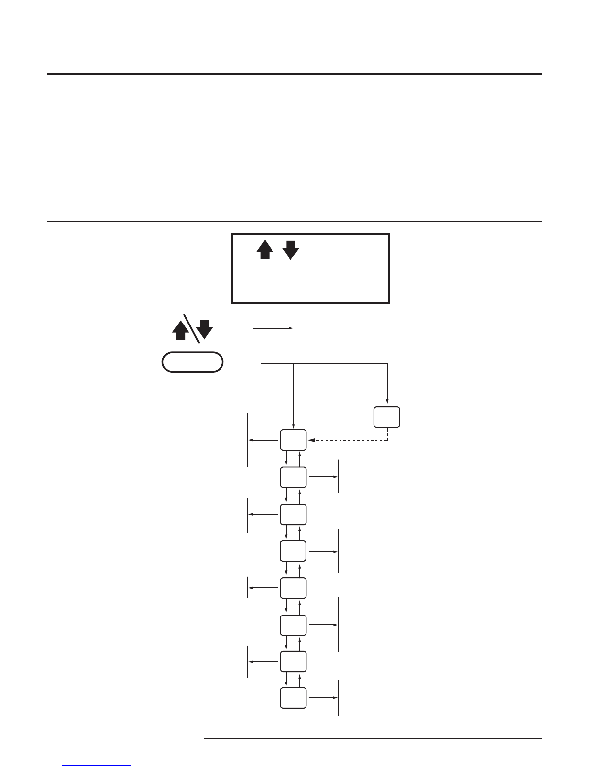
Programming the SPD
The SPDs versatility allows it to be completely
programmed (with the exception of inputting
custom curve tables) using either the front mounted
buttons and the SPDs menu, or our Intelligent PC
Configuration Software.
Figure 7. SPD Main Configuration Menu
Site-Programming the SPD
The SPDs front-facing menus are easy to use, and can
configure every parameter except inputting the custom
curve table. Connect the SPD as shown in Installing
the SPD, then use the arrow buttons to click through
the menu options and the Select button to select your
choice. Figure 7 below shows the main menu options
of the SPD.
12 Demand Moore Reliability

SPD
Programmable Field-Mount
Loop Display (NEMA 4X, IP66)
PC Programming the SPD
Using the PC software, you can change every one of
the SPDs parameters. Once these software settings
are made, they are “downloaded” to the transmitter
in the form of a Configuration File and stored in the
nonvolatile unit memory. You can choose to save
a backup copy of the file on your PC hard drive or
diskette.
Installing the PC Configuration Software
Refer to Table 2 for the equipment needed.
1. Insert the Moore Industries Interface Solution
PC Configuration Software CD into the CD
drive of the PC. Access the CD and open the
PSD SPD PC Configuration Software folder.
2. Double-click the installation program located
in the folder. Follow the prompts to correctly
install the program.
Table 2. Assembling the necessary equipment.
Device Specifications
Multimeter or
Ammeter
Variable Current
Source
Personal Computer
PC Operating
System
Moore Industries
PC Configuration
Software
Once the Configuration Program is installed on the
PC, the SPD can be connected to the loop or to
equipment to simulate and calibrate input. You can
then view and/or change the instrument’s parameters.
Once the program is loaded and running, nearly all of
the operating parameters for the connected transmitter
are shown on a single screen. This makes it easy to
determine which aspects of transmitter operation need
to be changed to suit the application requirements.
Accurate to ±0.025% of span;
e.g., Fluke Model 87
Capable of 4-20mA; accurate to ±0.01%
of span
Microsoft Windows based PC;
16Mb free RAM; 20MB free disk space on
hard drive
1 (one) serial port or one available USB
port (with optional USB cable)
Microsoft Windows XP, Vista or 7
Version 1.0 or higher, successfully installed
to the hard drive
Once the Configuration Program is installed on
the PC, the unit can be connected to equipment to
simulate input, monitor output, and view or change
the SPD’s operating parameters. Using the PC
Program to configure the SPD is accomplished in just
a few simple steps: Installation, Programming the
Input and Output, Programming the Alarms (-2PRG
models only), and either Programming the Input Trim,
or Programming with a Custom Curve.
To review the configuration that is currently loaded in
the connected SPD use the Transfer/Get Setup feature
from the menu bar, or the right arrow tool from the tool
bar. This will cause all the current parameters to be
displayed.
Downloading the Configuration
After the configuration has been set to your
satisfaction, it can be downloaded to the unit by
selecting Download from the Transfer menu or
by pressing the Download button on the toolbar.
Downloading the configuration displayed in the PC
program overwrites the unit’s current configuration.
Downloading the configuration to the SPD may take
up to 30 seconds to complete. It is important to let the
sequence finish before taking any other action.
Once completed, the Input Settings, Display Settings,
and Device portions of the screen will change to
match the configuration listed on the rest of the
screen. The Status indicator in the top left hand corner
of the view will then indicate the program has reverted
back to its idle mode.
Note:
After uploading file (by pressing the Up Arrow), you
must to press the Right Arrow button to populate all
information into the configuration dialog area.
Demand Moore Reliability 13

SPD
Programmable Field-Mount
Loop Display (NEMA 4X, IP66)
Programming the Input & Output
The PC program provides a simple setup for the SPD.
If you are planning on setting up a custom linearization
curve for the SPD, jump ahead to the Programming
with a Custom Curve page. Or if you want to configure
a SPD without setting up a custom curve, follow the
steps below. Refer to the right side of Figure 6 for
illustration of the Input & Output page.
Input Settings
The INPUT SETTINGS box defines the zero and full
values that the loop will carry. If you need information
on hooking up the SPD to your PC so you can
program it, see the diagram on Installing the SPD.
There are two ways to select the Input Settings:
1. The best way to define these numbers is to hook
the SPD up to the loop (see Installing the SPD)
and set the loop to its zero value, then press the
CAPTURE ZERO button. When the dialog box
pops up, press OK. Next, set the loop to its full
value and press the CAPTURE FULL button.
Again, press OK on the dialog box. You will see
that the loop values were captured and placed into
the edit boxes by INPUT ZERO and INPUT FULL.
2. The second way to define these numbers is to
enter them into the edit box. Simply click on the
edit box and enter the values.
Tag
The tag is a 16-digit alphanumeric character that is
used to identify a specific SPD. It is only viewable
from the PC program. Enter a suitable name for your
transmitter in the edit box.
EGU
The EGU is the engineering unit that will be displayed
on the second line of the SPD display. It is limited to
5 characters made up of numbers, selected symbols,
and capital letters.
Linearization Mode
If you are planning to use a normal, linear equation by
inserting the zero and full input values on the INPUT/
OUTPUT tab, keep the LIN. MODE set to NORMAL.
Setting this to CUSTOM disables the normal linear
curve and moves you to the CUSTOM CURVE portion
of the program, where you can setup a custom
linearization curve.
Filter
The filter is designed to eliminate mains-induced noise.
Set this to the Hz rating of the country that you are in.
When you have finished changing all your settings,
press the download button to transmit the information
to your SPD. It will place the information in nonvolatile
memory so that if a power outage occurs, you won’t
lose your settings.
Note:
None of these values will affect the SPD until they
are downloaded to the instrument. When you have
set every value that you need to change, press the
download button to finish the process.
Display Settings
The DISPLAY SETTINGS box controls what numbers
the display shows. This setting gives the SPD the
ability to convert the 4-20mA loop signal to a reading
in engineering units. To set the SPD to display the
appropriate numbers, enter the zero and full values for
the measurement into the appropriate edit boxes.
A typical example of zero and span values for a loop
transmitting temperature information would be 0° and
100° C, respectively.
14 Demand Moore Reliability
Display Resolution
The DISPLAY RESOLUTION table permits you to
change the number of decimal points that the SPD
displays. The AUTO selection causes the decimal
place to automatically adjust to the largest number of
decimal points possible. Other options permit you to
select from zero (NONE) to three decimal points. Set
this to the appropriate decimal point.
Damping Time
The damping function of the SPD allows the user to
introduce a delay into the displays response to the
loop power in order to make a fluctuating loop easier to
read. The value of the output damping is the number
of seconds that it will take for the display to make a
63% change in response to the change in input. A
damping time of “0” will disable damping.

SPD
Programmable Field-Mount
Loop Display (NEMA 4X, IP66)
Programming the Alarms Function
(Only for units with the -2PRG option)
The Alarms tab allows you to set the trip points,
deadband value, fail high/low, and failsafe/non-failsafe
values of the SPD. Note that only SPDs with the
-2PRG option have alarm capability.
Figure 8. The PC Program’s Alarm Parameters Tab
Delay
The Delay Value represents the amount of time delay
between the input exceeding the trip point and setting
the actual state change of the alarm. Delay values are
available between 0 and 120 seconds.
Capture Trip Point
The Capture Trip Point button permits you to attach
the SPD into the loop and read the trip point from the
transmitter. Simply press the Capture Trip Point button
and a wizard will pop up to guide you through the
process.
Programming the Trimming
Parameters
The Trimming tab helps you to match the zero and
full range values of the SPD to those of the loop
it is connected to. Essentially, it is correcting any
inaccuracies with the process variable transmitter. To
begin this simple process, connect the SPD into the
loop as shown in Installing the SPD, and press the Trim
Zero Now or the Trim Full Now buttons. A software
window will appear to guide you through the process. If
you change your mind, select Factory Trim Mode and
the SPD will return to the factory calibration values.
Alarm Settings & Terms
Use the Alarm 1 and 2 Settings portions of the screen
to set the Trip and Deadband values for alarms 1 and
2, respectively. The Trip Value is the point at which the
alarm goes into an on position. The Deadband Value
controls how far back past the trip point the process
variable has to go before the alarm switches back to
the off position. For example, if you have an alarm
trip high of 50 and a deadband of 10, then after the
process variable reaches 50, it must go down past 40
before the alarm shuts off
(trip of 50 – deadband of 10 = 40).
Fail High/Low & Failsafe/Non-Failsafe
Fail High causes the SPD to alarm when the process
variable goes over the set trip point, while Fail Low
causes the SPD to alarm when the process variable
goes under the trip point. Failsafe alarms are
de-energized when tripped, and energized when the
process input is at a non-alarm level. Non-Failsafe
alarms are energized whenever tripped, and deenergized when the process is at a non-alarm level.
Figure 9. The PC Program’s Trimming Tab
Demand Moore Reliability 15

SPD
Programmable Field-Mount
Loop Display (NEMA 4X, IP66)
Programming with a Custom Curve
The custom curve tab allows you to setup a custom
curve of up to 128 points. If you are looking for a
description of a specific part of the custom curve, click
on the graphic below. To setup a custom curve, simply
follow the steps below. To import a custom curve
instead of designing one, follow the instructions in
Importing a Custom Curve.
Linearization Data
Use the Linearization Data portion of the screen to set
the number of linearization points you will have in your
table and to enter the actual linearization points. In the
linearization table, insert the loop value in mA into the
X Column; in the Y column, enter the corresponding
data (i.e., the °C, °F, Gallons, PSIG, Millimeters, etc.).
If you are planning to display the data in the Y column
in the same EGU’s as those in the table, click the Grab
button to grab both the zero and full display settings
from the table.
Figure 10. The PC Program’s Custom Curve Parameters Tab
Note:
When entering data in the linearization table, make
sure that you enter a number into every open cell.
You may want to use some of the buttons listed in
the Commands box below to help when entering
linearization points.
Linearization Mode
If you are planning to use a custom curve, leave this
button set at CUSTOM. Changing it to NORMAL will
switch modes and cause the SPD to assume a normal,
linear equation.
Input Settings
This section controls the mA that you expect to read
off of the loop. Enter in the zero span and full span
data for the loop by clicking on the text boxes and
typing in the information.
Display Settings
This section allows you to replace the displayed value
with a different value than what is in the custom table.
For example, if your Y column of the table had a range
of 0-100, and you input a zero value of 0 and a full
value of 50 into the Display Settings section, then
when you received full input into the SPD, it would
read 50; when you received 25% of span in the SPD, it
would read 12.5. This is helpful if you set up a complex
custom curve and then need to change the output
values at a later time. You can also use it to reverse
the display output; showing a decreasing value on the
display as the input rises.
If you are planning on displaying a different value
and EGU than what is listed in the table, follow the
instructions in Display Settings (a few sections down).
You would use this function for example, if you wanted
to input the table in °C but display the percent of span
by placing 0 and 100 in the Display Setting boxes.
16 Demand Moore Reliability
Note:
If you are not planning on using this feature, make
certain that the Display Settings button matches the
custom curve information by clicking on the Grab
button.
When you have finished changing all your settings,
press the download button to transmit the information
to your SPD. It will place the information in nonvolatile
memory so that if a power outage occurs, you won’t
lose your settings.

SPD
Programmable Field-Mount
Loop Display (NEMA 4X, IP66)
Programming the SPD with a Square
Root Table
Moore Industries provides two options for customers
that require a square root linearization table. You can
either generate your own custom curve table or use a
curve table that is already provided.
Option One:
Generating a Custom Square Root Curve
The first option is to run the Square Root Table
Generator and create a custom square root table that
can be easily saved and imported into the Universal
PC Configuration Software. To generate your own
table, follow the instructions below.
1. From the START Menu, click on PROGRAMS,
MOORE INDUSTRIES, then CURVE GENERATOR.
2. Enter the values for the input and display into the
appropriate boxes. Enter the number of linearization
points that you would like generated into the NUMBER
OF LIN. POINTS box.
3. Click on GENERATE to create the table, then enter
the name you would like the table saved as.
4. Close the Square Root Curve Generator and open
the Universal PC Configuration Software. Click on
the FILE menu, then on IMPORT CUSTOM CURVE.
Select the “view all files” on the OPEN dialog box,
then find the file name that you just saved. (it’s
default directory is “C:\My Moore Industries Data\
Custom Curves”) and click OPEN. The Universal PC
Configuration Software will import the file.
5. Verify all settings.
6. Use the download button to transmit the new
custom table to the instrument and finish the process.
Option Two:
Importing a Pre-made Square Root Curve
The second option is to use a pre-made custom curve
table that works with the square root function. To
import the file, follow the instructions below.
1. In the Universal PC Configuration Program, click on
the FILE menu, then on IMPORT CUSTOM CURVE.
Select the “view all files” on the OPEN dialog box,
then find the file named “SquareRoot_0-100PCT.csv”
(it will be in the “C:\My Moore Industries Data\Custom
Curves” Directory) and click OPEN. The Universal PC
Configuration Software will import the file.
2. Verify all settings.
3. Use the download button to transmit the new
custom table to the instrument and finish the process.
Demand Moore Reliability 17

SPD
Programmable Field-Mount
Loop Display (NEMA 4X, IP66)
Importing a Custom Curve Table
Instead of having to re-enter your custom curve
information that you have already entered into a
program like Microsoft Word, Excel, or Notepad, you
can import the file to our Universal PC Configuration
Software. This can be a file you have created, or a file
that came pre-made with our software.
If you are interested in using the square root function,
use our Square Root Table Generator Program to
generate a custom table.
To import a different custom curve file, follow the steps
below.
1. To compose a file in Word or Notepad, make sure
that you have two float values per line with a comma
separating the two. Then save them as a .csv file. To
compose a file in Excel that is compatible with our
configuration software, enter the X values in column
one and Y values in column two. Save this file as a
comma-separated (.csv) file.
Note:
If you are using an equation to calculate your custom
curve, saving the file properly in Excel can be tricky.
To setup the file correctly, highlight the two columns
that correspond to X and Y in the Configuration Pro-
gram, then click EDIT and COPY. Next, create a new
file, and go to EDIT and PASTE SPECIAL. When it
prompts you regarding how to paste the information,
tell Excel to paste it as “Values”. Then save the file as
a comma-separated (*.csv) file. Go to step 2.
Exporting a Custom Curve Table
Exporting a custom curve can be useful if you want to
use Excel or another spreadsheet program to edit the
custom curve for your instrument or if you want to use
an already-created curve in another Moore Industries
PC Program.
All you need to do to export a custom curve from the
PC Configuration Program is to follow the steps below.
1. In the Universal PC Configuration Program, click on
the FILE menu, then on EXPORT CUSTOM CURVE.
Enter the name of the file into the appropriate field and
click the SAVE button. Your file has now been saved.
2. Use any program that will open a comma-separated
file (.csv) to edit the table.
2. In the Universal PC Configuration Program, click on
the FILE menu, then on IMPORT CUSTOM CURVE.
Find the appropriate file and click OPEN. The Universal PC Configuration Software will import the file.
3. Use the download button to transmit the new custom table to the instrument and finish the process.
18 Demand Moore Reliability

SPD
Programmable Field-Mount
Loop Display (NEMA 4X, IP66)
A1
SELECT
SITE PROGRAMMABLE
DISPLAY
163mm
(6.42 in)
96mm
(3.78 in)
78mm
(3.07 in)
96mm
(3.78 in)
116mm
(4.57 in)
121mm
(4.76 in)
Conduit
Opening for
Input Wiring
Conduit
Opening for Alarm
Tr ip Output Wiring
(Units with -2PRG Option)
FRONT VIEW
SIDE VIEW
BOTTOM VIEW
Figure 10. SPD Dimensions
Demand Moore Reliability 19

SPD
Programmable Field-Mount
Loop Display (NEMA 4X, IP66)
SPD Security
To protect the operational settings, the SPD is
equipped with a security password. Insure that the
Password Jumper is in the ON position. With the
password protection ON, making changes to the SPD
configuration via the front-panel buttons can only take
place after entering a two-digit, user-defined code.
With password protection OFF, the user can make
changes freely to the SPD settings, including to the
password code itself.
Note:
Setting the password jumper to On only inhibits
access to the SPD’s configuration via the front-panel
buttons; it does not affect the PC Software’s ability to
access and change the SPD’s configuration.
Changing the Password Security Setting
To change the security setting, turn off the power,
remove the right side of the SPD, and change the
jumper position as shown. When you are finished,
reapply power to the SPD. The SPD password
security setting will only change after the SPD power
has been turned off and on.
Customer Service
If service assistance is ever required for one of the
SPDs in your application, refer to the back cover of this
manual for the telephone numbers to Moore Industries
STAR Center customer service department.
If possible, make a note of the model number of the
offending unit before calling. For fastest assistance, try
to gather information on the unit(s) serial number and
the job and purchase order number under which it was
shipped.
Figure 10. Setting the Security Password Jumper
PASSWORD
SECURITY OFF
SECURITY
JUMPER
PASSWORD
SECURITY ON
INTERNAL
RIGHT SIDE VIEW
–IN
+IN
PC COMM.
CABLE
SECURITY
JUMPER
+24VDC
COM
20 Demand Moore Reliability

RETURN PROCEDURES
United States • info@miinet.com
Tel: (818) 894-7111 • FAX: (818) 891-2816
Australia • sales@mooreind.com.au
Tel: (02) 8536-7200 • FAX: (02) 9525-7296
Belgium • info@mooreind.be
Tel: 03/448.10.18 • FAX: 03/440.17.97
The Netherlands • sales@mooreind.nl
Tel: (0)344-617971 • FAX: (0)344-615920
China • sales@mooreind.sh.cn
Tel: 86-21-62491499 • FAX: 86-21-62490635
United Kingdom • sales@mooreind.com
Tel: 01293 514488 • FAX: 01293 536852
To return equipment to Moore Industries for repair, follow these four steps:
1. Call Moore Industries and request a Returned Material Authorization (RMA) number.
Warranty Repair –
If you are unsure if your unit is still under warranty, we can use the unit’s serial number
to verify the warranty status for you over the phone. Be sure to include the RMA
number on all documentation.
Non-Warranty Repair –
If your unit is out of warranty, be prepared to give us a Purchase Order number when
you call. In most cases, we will be able to quote you the repair costs at that time. The
repair price you are quoted will be a “Not To Exceed” price, which means that the
actual repair costs may be less than the quote. Be sure to include the RMA number on
all documentation.
2. Provide us with the following documentation:
a) A note listing the symptoms that indicate the unit needs repair
b) Complete shipping information for return of the equipment after repair
c) The name and phone number of the person to contact if questions arise at the factory
3. Use sufficient packing material and carefully pack the equipment in a sturdy shipping container.
4. Ship the equipment to the Moore Industries location nearest you.
The returned equipment will be inspected and tested at the factory. A Moore Industries representative will contact the person designated on your documentation if more information is
needed. The repaired equipment, or its replacement, will be returned to you in accordance
with the shipping instructions furnished in your documentation.
WARRANTY DISCLAIMER
THE COMPANY MAKES NO EXPRESS, IMPLIED OR STATUTORY WARRANTIES (INCLUDING ANY WARRANTY OF MERCHANTABILITY OR
OF FITNESS FOR A PARTICULAR PURPOSE) WITH RESPECT TO ANY
GOODS OR SERVICES SOLD BY THE COMPANY. THE COMPANY DISCLAIMS ALL WARRANTIES ARISING FROM ANY COURSE OF DEALING
OR TRADE USAGE, AND ANY BUYER OF GOODS OR SERVICES FROM
THE COMPANY ACKNOWLEDGES THAT THERE ARE NO WARRANTIES
IMPLIED BY CUSTOM OR USAGE IN THE TRADE OF THE BUYER AND
OF THE COMPANY, AND THAT ANY PRIOR DEALINGS OF THE BUYER
WITH THE COMPANY DO NOT IMPLY THAT THE COMPANY WARRANTS
THE GOODS OR SERVICES IN ANY WAY.
ANY BUYER OF GOODS OR SERVICES FROM THE COMPANY
AGREES WITH THE COMPANY THAT THE SOLE AND EXCLUSIVE REMEDIES FOR BREACH OF ANY WARRANTY CONCERNING THE GOODS OR
SERVICES SHALL BE FOR THE COMPANY, AT ITS OPTION, TO REPAIR
OR REPLACE THE GOODS OR SERVICES OR REFUND THE PURCHASE
PRICE. THE COMPANY SHALL IN NO EVENT BE LIABLE FOR ANY CONSEQUENTIAL OR INCIDENTAL DAMAGES EVEN IF THE COMPANY FAILS
IN ANY ATTEMPT TO REMEDY DEFECTS IN THE GOODS OR SERVICES
, BUT IN SUCH CASE THE BUYER SHALL BE ENTITLED TO NO MORE
THAN A REFUND OF ALL MONIES PAID TO THE COMPANY BY THE BUYER
FOR PURCHASE OF THE GOODS OR SERVICES.
ANY CAUSE OF ACTION FOR BREACH OF ANY WARRANTY BY
THE COMPANY SHALL BE BARRED UNLESS THE COMPANY RECEIVES FROM THE BUYER A WRITTEN NOTICE OF THE ALLEGED
DEFECT OR BREACH WITHIN TEN DAYS FROM THE EARLIEST DATE
ON WHICH THE BUYER COULD REASONABLY HAVE DISCOVERED
THE ALLEGED DEFECT OR BREACH, AND NO ACTION FOR THE
BREACH OF ANY WARRANTY SHALL BE COMMENCED BY THE
BUYER ANY LATER THAN TWELVE MONTHS FROM THE EARLIEST
DATE ON WHICH THE BUYER COULD REASONABLY HAVE DISCOVERED THE ALLEGED DEFECT OR BREACH.
RETURN POLICY
For a period of thirty-six (36) months from the date of shipment, and under
normal conditions of use and service, Moore Industries (“The Company”)
will at its option replace, repair or refund the purchase price for any of its
manufactured products found, upon return to the Company (transportation
charges prepaid and otherwise in accordance with the return procedures
established by The Company), to be defective in material or workmanship.
This policy extends to the original Buyer only and not to Buyer’s customers
or the users of Buyer’s products, unless Buyer is an engineering contractor
in which case the policy shall extend to Buyer’s immediate customer only.
This policy shall not apply if the product has been subject to alteration,
misuse, accident, neglect or improper application, installation, or operation.
THE COMPANY SHALL IN NO EVENT BE LIABLE FOR ANY INCIDENTAL
OR CONSEQUENTIAL DAMAGES.
 Loading...