

Page 1

May 2016
149-733-00 D
Programmable Isolated
RTD Transmitter
RIY
Programmable Isolated
RTD Transmitter
RIY
Page 2

Table of Contents
Introduction 1
Description 1
Calibration 3
Installation 13
Operation 14
Maintenance 19
Page 3

RIY
Introduction
Moore Industries’ Programmable Isolated RTD
Transmitter (RIY) is a 2-wire, microprocessor-based
instrument that converts an RTD or ohms input into a
4-20 mA output. The output is field-configurable to be
linear with temperature or linear with an ohms input.
The highly accurate RIY features easy-to-use push
buttons, a rotary switch, and a SIP switch for field
calibration and configuration.
This manual contains descriptive, calibration, installation, and operation information for the RIY. Also
included in this manual is a quick reference page
containing often referred to setup and hookup information (see appendix A).
Notes and cautions are provided throughout this
manual to help you avoid minor inconveniences
(NOTES) and equipment damage (CAUTIONS).
Description
The RIY is a loop-powered, RTD transmitter that
accepts an input from 2-, 3-, or 4-wire RTD’s, or a
resistance source. The RIY processes the input
signal using digital technology and produces a
proportional 4-20 mA output.
• Readouts in degrees Celsius or Fahrenheit, or
ohms (only on units with LCD’s)
• Sensor type and number to be input to the RIY
• Upscale/downscale drive
• Quick/standard ranging
• Keyboard lockout/enable
The RIY is available in two housing styles; a hockeypuck (HP) housing and a DIN-style housing. Both
housing styles have the same operational features
and offer the same options. The intended application
of the RIY must be clearly identified to determine
which housing style is most suitable.
The standard HP-style housing is equipped with
spring clips for mounting in explosionproof enclosures. An RIY packaged in an HP-style housing and
equipped with flange plates (FL Housing option) is
designed to mount on a flat surface or on relay tracks.
The configuration switches for HP-style units are
accessible through a removable panel at the rear of
each unit.
The all-aluminum DIN-style housing snaps directly
onto standard G-type or Top-hat DIN rails. The
configuration switches for DIN-style units are accessible through a removable panel on the upper rightside panel of the unit. The physical layout of the
configuration switches in DIN-style units is identical to
that of HP-style units.
Tactile push buttons, located on the front panel, are
used to set the zero and span (full-scale). The values
entered are stored in an EEPROM and remain, even
when power is removed, until the values are changed
by the user. The push buttons provide greater
calibration accuracy and stability than do potentiometer adjustments of non-microprocessor-based
instruments.
A 4-digit, liquid crystal display (LCD) is standard on
the RIY. (The RIY is available without the LCD.) This
display provides readouts of the applied input (either
in temperature or ohms), and it displays problem
codes. (The LCD is required for
Switches are used to configure several functional
characteristics of the RIY. Each of these switches is
accessible without disassembling the unit. The
switch-selectable features include:
quick ranging
Table 1 contains the operational and performance
specifications for the RIY.
Options
The RIY is available with several optional features.
The following is a brief description of the most
popular options:
DD Option — Downscale drive on loss of input
(upscale drive is standard)
.)
ND Option — No display (LCD)
For availability of other options, including intrinsic
safety approvals, contact your local Sales Representative or Moore Industries’ directly.
The Interface Solution Experts
1
Page 4
RIY
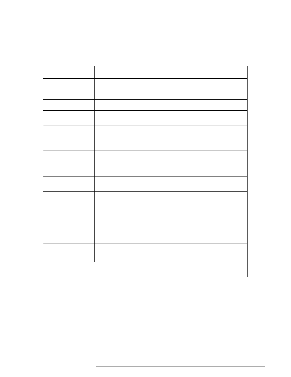
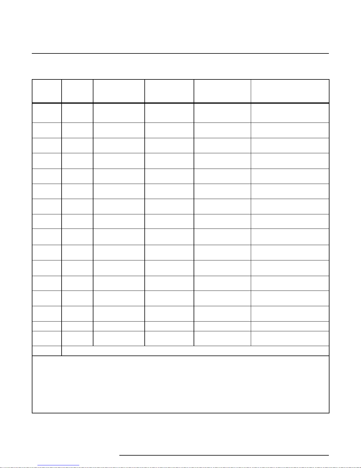
Table 1. RIY Operational and Performance Specifications
Characteristic
Input
Output
Power
Controls
Indicators
Fault
Response
Performance
Specification
RTD’s, 2-, 3-, or 4-wire (single, dual, or triple sensors)
Ohms, 0-4000Ω
(refer to the Calibration Section for ranges)
4-20 mA – linear with temperature or ohms input (switch-selectable)
12-42 Vdc loop-power, standard
12-30 Vdc, I.S. version
Four front panel push buttons: used to set zero and span; SAVE
function (2 'up' buttons); and CANCEL function (2 'down' buttons)
Switches: Used to set the unit’s operating configuration (see Calibration
Section for application of switches)
Liquid Crystal Display: 4-digit LCD; diaplays input values; zero and
full-scale values; problem codes; and high and low table limit warnings
(RIY available without LCD)
LCD Accuracy: ±0.1% of maximum span, ±1 digit
On Loss of Input: Upscale drive to 21.4 mA; downscale drive to 3.6 mA
(switch-selectable)
Accuracy: ±0.05% of span (refer to table 2 for accuracy by input type)
Isolation: Galvanic isolation between input and output up to 1000 Vdc
Stability: ±0.1% of calibrated span for 6 months
Ripple: <10 mV P/P, maximum (up to frequencies of 120 Hz) measured
across a 250Ω load resistor
RFI/EMI Susceptability: 30 V/m – abc -0.1% of ohms reading as
defined by SAMA 33.1 (HP and DIN units)
Ambient Temperature Effect: All combined effect, ±0.006% of span/°C
±10 ppm of ohms reading/°C
Environmental
Ratings
NOTE: Refer to the Installation Section of this manual for housing dimensions.
Unit Data Tracking – Model/Serial Numbers. Moore
Industries keeps a record of configuration information
on every unit it sells or services. This information is
keyed to the unit model and serial numbers.
The serial and model number for the HP-style RIY is
located on the back panel of the unit. The serial and
2
The Interface Solution Experts
Ambient Operating Temperature: –40 to 82 °C (–40 to 180 °F)
Storage Temperature: –40 to 100 °C (–40 to 212 °F)
model number for the DIN-style unit is located on
the right-side panel of the unit.
If product information is ever required, make a note
of the unit model number before contacting the
factory. For fastest assistance, also note the unit
serial number, and the job number and purchase
Page 5
RIY
order number under which the unit was shipped. This
information assists our factory representative in
providing you with the answers you need as efficiently
as possible.
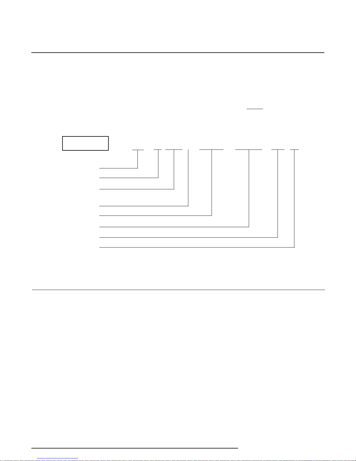
EXAMPLE
Unit Type
Input Code
Calibration Value
Input Units of
Measure
Output
Power
Option(s)
1
2
3
RIY / R0-0-100 C / 4-20MA / 12-42DC / -ND [HP]
The following example identifies the significance of
each field of the RIY model number. Refer to this
example in deciphering the model number of your
RIY.
NOTE
Consult the factory for availability of
specific configuration options.
Housing
1
Table 2 lists the input range for each model number Input Code.
2
Indicates the input range used for factory calibration.
3
F, Fahrenheit; C, Celsius; OHMS, ohms
Calibration
Prior to shipment, every RIY is factory-checked using
automated test equipment. Duplication of the factory
check is not expected nor intended for the field.
However, field calibration procedures involving use of
the front panel push buttons and the configuration
switches are described in this section for field applications.
Both the HP- and DIN-style housings are available
with the same options, and they have the same push
button and switch arrangements. The following
descriptions of the push buttons and configuration
switches pertain to both housing styles.
Using the Push Buttons
The RIY is equipped with a membrane panel that
contains four tactile push buttons used to set zero
and span (full-scale). Figure 1 shows the layout of
the membrane panel for both the HP- and DIN-style
units. Each push button is labeled with an Up or
Down arrow inside a circular background that is
contoured to the membrane-panel surface.
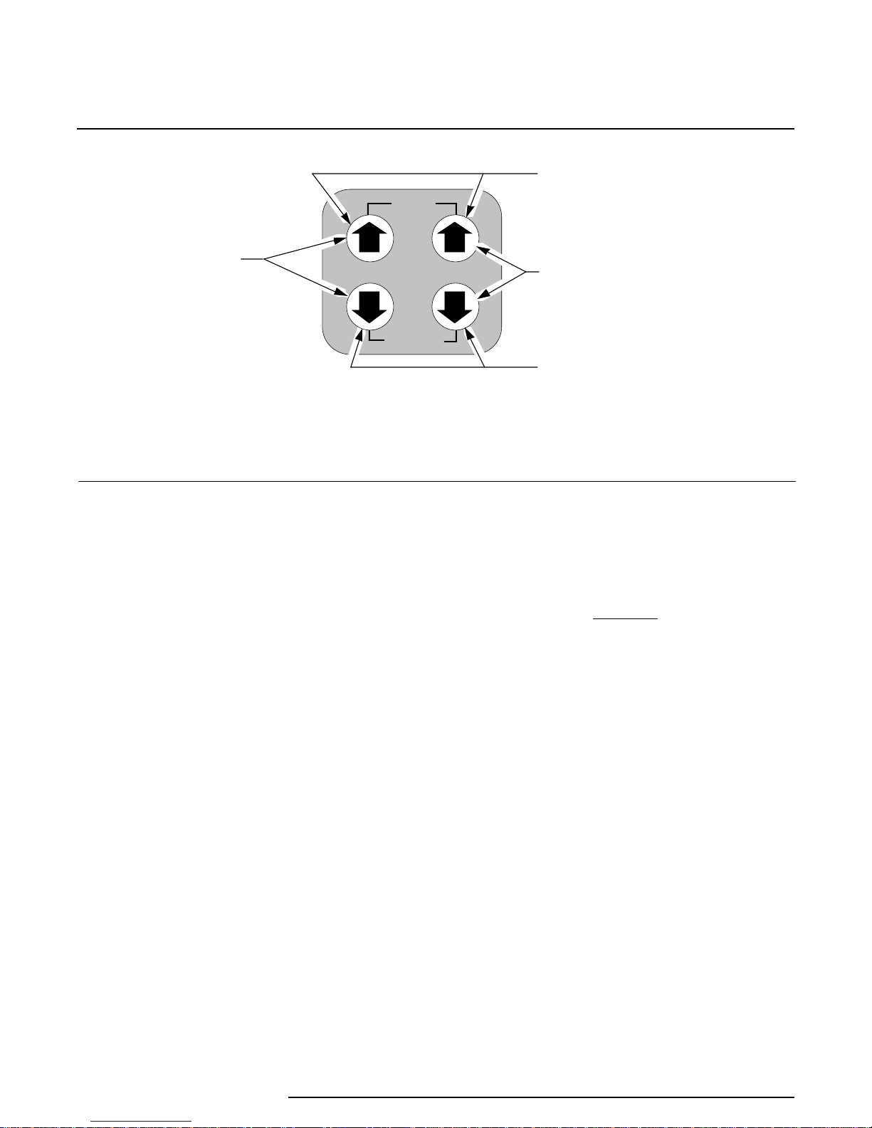
The functions of the push buttons are labeled
“ZERO”, “SPAN”, “SAVE”, and “CANCEL”. When the
arrows are pressed individually or in certain simultaneous combinations, one of these four functions is
affected.
The Interface Solution Experts
3
Page 6
RIY
USED TO SET
OR TRIM ZER O
SAVE
ZERO SPAN
CANCEL
Figure 1. RIY Front Panel Push Buttons
USED TO SAVE
CALIBR ATION VALUES
USED TO SET OR
TRIM FULL SCALE
USED TO D ISREGARD LAST
ENTRY AND RETURN TO
OPERATE M OD E
The Up arrows:
• display the latest calibrated setting for zero or
span, respectively, when pressed individually
during normal operation (units with LCD’s
only); does not affect the output of the RIY
• increment zero or span values, respectively,
when pressed individually while in
ranging
• increment the ‘trim’ value for the zero- and 100percent output levels in
• save the calibration setting for zero or span
while in the calibrate mode, then returns the
unit to normal operation, when both are
pressed simultaneously
(units with LCD’s only)
standard ranging
quick
The Down arrows:
• display the latest calibrated setting for zero or
span, respectively, when pressed individually
during normal operation (units with LCD’s
only); does not affect the output of the RIY
• decrement zero or span values, respectively,
when pressed individually while in
ranging
• decrement the ‘trim’ value for the zero- and
100-percent output levels in
• cancel the calibration mode and returns the unit
to normal operation when both are pressed
simultaneously; retains previous values
(units with LCD’s only)
quick
standard ranging
Pressing the ZERO or SPAN Up and Down arrows
simultaneously sets the unit to the calibrate mode (if
enabled through switch settings) for that particular
setting.
CAUTION
The push buttons are not designed to be
actuated with sharp, pointed objects.
Using a pen, screwdriver, or other sharp
object will damage the push buttons.
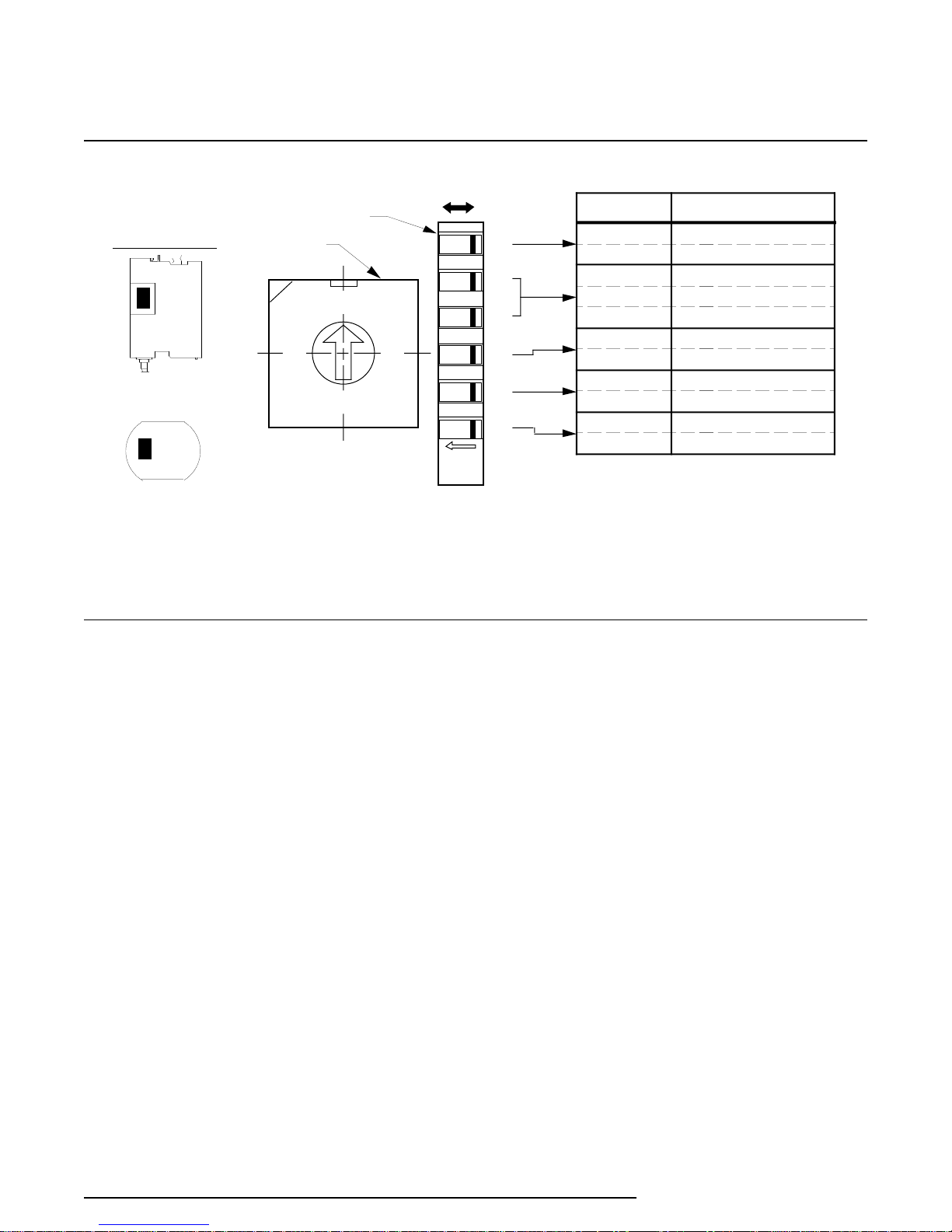
Using the Configuration Switches
A rotary switch and a single in-line package (SIP)
switch are used to configure the RIY for user-selectable operating and calibration parameters.
Figure 2 shows the layout of the configuration
switches and the switch setting options for SW301.
The switch settings for rotary switch SW302 are listed
in table 2. The reference designators and physical
layout of the switches in the HP- and DIN-style units
are identical.
The switches for HP-style units are accessed through
a cutout at the rear of the unit. The cutout is filled
with a small, removable panel. A narrow, slottedhead screwdriver may be used to gently pry the panel
off the unit to access the switches.
4
The Interface Solution Experts
Page 7
RIY
ORIENTATION
DIN
HP
3
4
5
6
ON OFF
-1
-2
-3
-4
-5
-6
SW 301
SW 302
0
1
F
E
2
D
C
B
A
NOTES: 1. Refer to table 2 for SW 302 swi tch setti ng us es.
2. The relative posi ti on of SW 301 and SW 302 i s identi cal for HP- and D IN - s tyle units.
3. SW 301- 6 m ay be inacti ve in earlier units. In thes e units, the s w itch setti ng can be disr egar ded.
Figure 2. Internal Switches, Layout, Designations, and Settings
7
8
9
SETTINGS FEATURES
ON
OFF
-2 OFF /-3 OFF
-2 OFF /-3 ON
-2 ON/-3 ANY
ON
OFF
ON
OFF
ON
OFF
DISPLAYS CELSIUS
DISPLAYS FAHRENH EIT
2-WIRE, DUAL 2-WIRE
3-WIRE, DUAL 3-WIRE
4-WIR E, TR IPLE 2- W IR E
DOWNSC ALE DRIVE
UPSC ALE DRIVE
QUICK RANGING
STANDARD RANGING
KEYBOARD LOC KOU T
KEYBOARD EN ABLE
Switches for DIN-style units are accessed by removing a small, L-shaped panel from the upper right-side
of the unit. This panel is bent over the top, right-side
edge of the unit and is secured with a single screw on
top. A Phillips-head screwdriver is required to
remove one screw securing the small L-shaped panel
to the housing frame.
The configuration switches are used to set the
following features:
SW301-1 — Displayed Temperature Type
ON – Sensor input displayed in Celsius
OFF – Sensor input displayed in Fahrenheit
This switch determines the type of temperature
units that will be displayed on the LCD. If an
ohms range is selected, the display will show
OHMS and this switch is ignored.
SW301-2 & -3 — Number of Wires or Sensors
These two switches determine the number of
wires for a single sensor input, or the number of
sensors of a multi-sensor input configuration.
Refer to table 2.
SW301-4 — Upscale/Downscale on Fault
ON – Downscale Output Drive on Fault
OFF – Upscale Output Drive on Fault
This switch determines the reaction of the RIY
output when an error is detected (during poweron diagnostics) or when an input or sensor lead is
physically open.
SW301-5 — Ranging Method
ON – Quick Ranging (for units with LCD’s only)
OFF – Standard Ranging
Quick Ranging
with an LCD. To set the 4-20 mA output with this
ranging method, dc power is the only input
needed for the unit. The pushbuttons are used to
set the zero and full-scale inputs.
Standard Ranging
output monitoring device, and dc power. The
push buttons are used to capture the zero and
full-scale input values and to trim the zero- and
100-percent output settings.
can only be performed on units
requires an input source, an
The Interface Solution Experts
5
Page 8
RIY
1
Input
Code
SW302
Setting
Table 2. RTD and Ohms Input by Input Code (SW302 Settings)
Input
Type
Description
Range
2,3
Accuracy Adjustments
±0.05% of Span, ±
R0
R1
R2
R3
R4
R5
R6
R7
R8
R9
R10
R11
R12
R13
R14
R15
PRG
0
1
2
3
4
5
6
7
8
9
A
B
C
D
E
F
Programmable input, unspecified at time of order; factory default of R0, -300 to +267 °F (see model number).
Pt 100Ω
385 RTD
Pt 100Ω
3923 RTD
Pt 100Ω
3916 RTD
Pt 100Ω
3902 RTD
Pt 200Ω
385 RTD
Pt 500Ω
385 RTD
Pt 1000Ω
385 RTD
Pt 1000Ω
375 RTD
Two Pt 100Ω
385 RTD’s, Ave.
Two Pt 100Ω
3923 RTD’s, Diff.
Two Pt 100Ω
385 RTD’s, Diff.
Two Pt 500Ω
385 RTD’s, Diff.
NI 120Ω
RTD
CU 10Ω
RTD
Ohms
FLEX-SOR
TM
100Ω at 0 °C,
α = 0.003850
98.129Ω at 0 °C,
α = 0.003923
100Ω at 0 °C,
α = 0.003916
100Ω at 0 °C,
α = 0.003902
200Ω at 0 °C,
α = 0.003850
500Ω at 0 °C,
α = 0.003850
1000Ω at 0 °C,
α = 0.003850
1000Ω at 0 °C,
α = 0.003750
2 or 3 of R0
Averaged
2 of R1
Differential
2 of R0
Differential
2 of R5
Differential
120Ω at 0 °C,
α = 0.00672
9.035Ω at 0 °C,
α = 0.00427
0-4000Ω
1000Ω at 0 °C,
α = 0.00285
–200 to 850 °C
(–328 to 1562 °F)
–200 to 600 °C
(–328 to 1112 °F)
–200 to 510 °C
(–328 to 950 °F)
–200 to 650 °C
(–328 to 1202 °F)
–200 to 630 °C
(–328 to 1166 °F)
–200 to 630 °C
(–328 to 1166 °F)
–200 to 630 °C
(–328 to 1166 °F)
–185 to 540 °C
(–301 to 1004 °F)
–200 to 850 °C
(–328 to 1562 °F)
–550 to 800 °C
(–990 to 1440 °F)
–550 to 1050 °C
(–990 to 1890 °F)
–550 to 830 °C
(–990 to 1494 °F)
–80 to 320 °C
(–112 to 608 °F)
–50 to 250 °C
(–58 to 482 °F)
0-4000Ω
–90 to 175 °C
(–130 to 347 °F)
0.20 °C
(0.36 °F)
0.20 °C
(0.36 °F)
0.20 °C
(0.36 °F)
0.20 °C
(0.36 °F)
0.13 °C
(0.23 °F)
0.10 °C
(0.18 °F)
0.10 °C
(0.18 °F)
0.10 °C
(0.18 °F)
0.20 °C
(0.36 °F)
0.40 °C
(0.72 °F)
0.40 °C
(0.72 °F)
0.20 °C
(0.36 °F)
0.14 °C
(0.25 °F)
1.6 °C
(2.9 °F)
0.2Ω
0.08 °C
(0.14 °F)
NOTES: 1. This column contains the Input Code for the model number of each RIY.
2. The lower table limit extends 5%, or more, of maximum span below the listed value. When this limit is
exceeded, the RIY will clamp at the limit value and the display will read “–LO–”. For ohms ranges, 0Ω is
the lower table limit.
3. The upper table limit extends 10%, or more, of maximum span above the listed value. When this limit is
exceeded, the RIY will clamp at the limit value and the display will read “–HI–”. For ohms range, 4095Ω
is the upper table limit.
6
The Interface Solution Experts
Page 9

RIY
SW301-6 — Keyboard Lockout/Enable
ON – Lockout
OFF – Enable
In some units
dard ranging when it is set to the ‘on’ position.
When set to the ‘off’ position, quick or standard
ranging can be performed. Even with this switch
in the ‘on’ position (lockout), the zero and span
settings of the unit can be viewed on units with an
LCD.
If you are uncertain of the functionality of
SW301-6 for a particular RIY, set it to
‘on’ and try to change the settings. If
you can change the settings, this switch
DOES NOT provide keyboard lockout.
SW302 — Range Select Switch
This is a 16-position rotary switch that is used to
configure the unit for a particular input range.
Refer to table 2 for switch settings.
Anytime a switch setting is changed while power is
applied, one of the front panel push buttons must be
pressed to ensure that the RIY accepts and acknowledges the configuration change.
, this switch inhibits quick or stan-
NOTE
Reading the LCD
The 4-digit, liquid crystal display (LCD) of the RIY
displays:
• the currently applied input in degrees Celsius
(°C), degrees Fahrenheit (°F), or ohms (Ω)
• the calibrated zero or span settings when called
for during normal operation
• zero and span input values during calibration
• “–LO–” or “–HI–” when the input value exceeds
the lower or upper range table limits for a
particular input range, as determined by the
setting of the Range Switch
• problem codes discovered by the self-diagnostics during power-up, calibration, or normal
operation (refer to the Operation Section for
code definitions)
The LCD is also used to perform
feature allows you to calibrate the RIY using predetermined representative zero and span (full-scale) input
values. However, quick ranging can only be performed on units with an LCD.
The LCD operates independently from the highly
accurate conversion circuits of the RIY. Field calibration of the LCD itself is typically not required, as the
performance of the LCD does not affect the accuracy
of the output. However, if the LCD readings drift
beyond the accuracy ratings stated in table 1, you
should consult the factory for LCD calibration requirements. To check the LCD’s accuracy in the field, the
RIY must be supplied a highly accurate and controllable input signal, and then the input device and the
RIY’s LCD readings compared.
The LCD on the RIY displays the input readings in
degrees Celsius, degrees Fahrenheit, or Ohms. The
values displayed in various functional modes are
either rounded off to the nearest whole digit or they
are exact values.
When the RIY is in any display mode other than quick
ranging, such as the operate mode, standard ranging,
or display zero or span values, the LCD displays input
values that are electronically rounded to the nearest
whole unit (e.g., 121, 1143, 237). Because the actual
input to the RIY includes temperature or resistance
values that are not exactly whole units (e.g., 120.6,
1142.91, 237.4), the RIY rounds off the input to the
nearest whole unit for display purposes. However,
the electronics process the exact input value.
When the RIY is in quick ranging, the values displayed are exact to the least significant whole unit
(e.g., 121.0, 1143.0 237.0), because these values are
computed internally.
Labels denoting the unit-of-measure that the display
reading indicates are provided with the RIY. These
adhesive-backed labels are marked “°F”, “°C”, and “Ω”.
These labels are sized to fit in the lower, angled
portion of the LCD frame. Figure 3 shows all three
labels at actual size.
quick ranging
. This
The Interface Solution Experts
7
Page 10

RIY
˚C
˚F
Figure 3. Units-of-Measure Labels for the LCD
‘Ranging’ the RIY
Ranging
features two methods of ranging;
To use either method, configuration switch SW301-5
must be set to the desired setting and SW301-6 must
be set to the ‘off’ position (see figure 2).
is a method of field calibration. The RIY
standard
and
quick
In standard ranging, input values for zero and span
must first be
Then, the output can be
percent output of 4 mA and a 100-percent output of
20 mA. But to effect any range changes, switch
SW301-6 must be set to the ‘off’ position (keyboard
enable).
Reverse Output. The RIY can also be set up for
reverse output
mA and the 100-percent output is 4 mA. To setup the
RIY for reverse output operation, the zero and span
settings must cross over one another. These
settings are made by capturing the
scale, input with the ZERO push buttons as described
in step 7 of the upcoming standard ranging procedure. Then, the span is captured in step 10 with the
.
SPAN push buttons when the input is zero percent for
a 100-percent output. When the zero output setting is
greater than the span output setting, the unit is
configured for reverse output operation.
captured
, where the zero-percent output is 20
by the RIY’s microprocessor.
trimmed
further for a zero-
greater,
or full-
Before ranging (or calibrating) the RIY, you should
verify all switch settings to ensure that the unit will
operate in a predictable manner. Refer to the subsection titled “Using the Configuration Switches”
presented earlier in this section for switch setting
options.
Standard Ranging Overview
Standard ranging is used to set the zero- and 100percent output settings of the RIY based on userselected input values. The input values are simulated
by calibration equipment to represent actual RTD or
resistance input values. Refer to a resistancetemperature table for ohm values representative of
RTD temperature values.
Standard ranging is the only field calibration possible
for units without an LCD. Whether your RIY has an
LCD or not, you should rely on the readings from the
calibration equipment while performing standard
ranging.
By setting switch SW301-5 to the ‘off’ position, the
unit is configured for standard ranging (see figure 2).
Trimming. ‘Trimming’ is a feature of standard
ranging that allows the user to vary the zero- and
100-percent output values using the ZERO and SPAN
push buttons, respectively.
Trimming the zero-percent setting varies the zero
reference point and the 100-percent output value,
proportionally. For this reason, when a new zero
input value is captured, all previously set trim values
are eliminated. The
constant while trimming the zero-percent output.
Trimming the 100-percent output with the SPAN push
buttons varies only the full-scale output value; the
zero reference point remains at the level it was last
set to. The zero-percent output should always be
trimmed before trimming the 100-percent output.
span
of the output remains
Standard Ranging Setup
To perform standard ranging you need an input
source, dc power source, and an output monitoring
device. Table 3 lists the calibration equipment and
the equipment accuracy required to perform this
method of ranging.
8
The Interface Solution Experts
Page 11

RIY
Figure 4 illustrates the calibration setup required to
perform standard ranging.
To monitor the output, a dc voltmeter and a precision
load resistor are called for. Volmeter readings of 1-5
Vdc read across a 250 ohm resistor represent 4-20
mA, proportionally. An output reading of 3 Vdc is
equal to a 12 mA output with a 250 Ohm resistor.
Similar calculations can be made over the 1-5 Vdc
range with the following conversion formula: V
(voltage reading)/250Ω = mA.
Table 3. RIY Calibration Equipment (Standard Ranging)
Equipment
Decade Resistance
Box
Voltmeter and
Precision Resistor
Specifications
Accuracy of ±0.01%, or better
Digital voltmeter, accuracy of ±0.005% or better; 250Ω precision
resistor, tolerance of ±0.01%
Standard Ranging Procedure
1. Set range and other configuration switches for the
required RTD or ohms input, as necessary (refer
to figure 2 and table 2).
NOTE
Switch SW301-5 must be set to the ‘off’
position to perform standard ranging,
and set switch SW301-6 to the ‘off’
position for units with this switch
functional for keyboard enable.
NOTES:
DC Power Source
DECADE
RESISTANCE
BOX
1. Terminals 1 and 4 are the primary connection terminals.
2. To simulate a 3-wire input, use terminal 3 for lead length
compensation
3. To simulate a 4-wire input, use terminals 2 and 3 for lead
length compensation.
(SEE NOTES)
Figure 4. Calibration Hookup Diagram (Standard Ranging)
12-42 Vdc
1
2
3
4
RIY
+PS
–PS
250
+
DC VOLTMETER
–
+
–
12-42 VDC
POWER
SOURCE
The Interface Solution Experts
9
Page 12

RIY
2. Connect RIY as shown in figure 4. Apply power.
3. Press and hold either the Up
or Down ZERO push button.
Note zero value displayed.
ZERO
4. Press and hold either the Up
or Down SPAN push button.
Note span (full-scale) value
SPAN
displayed.
5. To enter zero calibrate mode,
press the Up and Down
ZERO push buttons simulta-
ZERO
neously.
NOTE
In standard ranging, the LCD will
continually flash while in the calibrate
mode.
6. Set input device for zero-percent input to RIY.
7. To capture zero input value,
press (slowly) the Up and
Down ZERO push buttons
ZERO
simultaneously, twice.
NOTE
If the input value being captured
exceeds the upper or lower programmed
table limits for a particular input (refer to
table 2), the LCD will flash -HI- or -LO-,
respectively. The input value must be
within programmed table limits to be
displayed or captured.
Vdc (4 mA), repeat steps 6 and 7 until 5 Vdc
reading is obtained.
9. Set input device for full-scale input to RIY.
10. To capture full-scale input
value, press (slowly) the Up
and Down SPAN push
SPAN
buttons simultaneously,
twice.
11. Verify that voltmeter reading is 1 Vdc (4 mA).
This indicates that full-scale value was captured
successfully. If voltmeter reads 5 Vdc, repeat
steps 9 and 10 until 1 Vdc reading is obtained.
12. To trim zero-percent output,
while monitoring output,
press the Up or Down ZERO
ZERO
push button until desired
output reading is obtained
(e.g., 1.000 Vdc).
13. Press the Up and Down
SPAN push buttons simultaneously.
SPAN
14. To trim 100-percent output,
while monitoring output, press
the Up or Down SPAN push button until desired
output reading is obtained (e.g., 5.000 Vdc).
15. When desired values are
SAVE
captured and outputs
trimmed, press both Up
ZERO
SPAN
arrows simultaneously to
save latest settings.
16. Check zero and full-scale settings as described in
steps 3 and 4. If settings are correct, standard
ranging is complete. If not, repeat entire procedure.
8. Verify that voltmeter reading is 5 Vdc (equivalent
to 20 mA). This indicates that zero input value
was captured successfully. If voltmeter reads 1
10
The Interface Solution Experts
17. When procedure is complete, set SW301-6 to the
‘on’ position for keyboard lockout (for units with
SW301-6 functional).
Page 13

RIY
The settings entered during calibration are stored in an
EEPROM when the SAVE push buttons are pressed.
These setting are retained until a subsequent calibration (quick or standard ranging) is performed. If the
latest settings are not saved before removing power, or
if the CANCEL push buttons (both Down arrows) are
pressed simultaneously, the unit will revert to the
previously saved values.
Quick Ranging Overview & Setup
Quick ranging is a unique feature that allows the user
to calibrate an RIY equipped with an LCD, without the
use of an input source or an output monitoring device.
With switch SW301-5 set to the ‘on’ position and
SW301-6 is set to the ‘off’ position, a 12-42 Vdc
power source applied to the +PS and –PS terminals
of the RIY is all that is required to perform quick
ranging. The front-panel push buttons are used to set
zero and span (full-scale) values to user-selected
input settings that yield the desired zero- and 100percent outputs. The user selected values are
displayed on the unit’s LCD.
When quick ranging is selected, the RIY ignores any
input applied to the input terminals. The zero-percent
output will be 4 mA for whatever value zero is set to
with the ZERO push buttons, and the 100-percent
output will be 20 mA for whatever the full-scale value
is set to with the SPAN push buttons.
The RIY can be set up for reverse output using quick
ranging. To do this, simply increase the zero setting
beyond the full-scale setting, and decrease the fullscale setting below the zero setting. When the zero
and span output settings cross one another, reverse
output is achieved. The reverse output setup is
accomplished while selecting the zero and span
settings in the upcoming procedure.
Figure 5 illustrates the dc power hookup required to
perform quick ranging of the RIY.
If the unit is configured for standard ranging, the
display will continually flash the applied input value
when the Up and Down arrows are pressed simultaneously to enter the calibrate mode. Pressing the Up
or Down arrows will have no affect on the displayed
value. This reaction indicates that the unit is NOT
configured for quick ranging.
Quick Ranging Procedure
1. Set range and other configuration switches for the
required RTD or ohms input, as necessary (refer
to figure 2 and table 2).
NOTE
Switch SW301-5 must be set to the ‘on’
position to perform quick ranging, and
set SW301-6 to the ‘off’ position for units
with this switch functional for keyboard
enable.
12-42 VDC
POWER
SOURCE
NOTES: 1.
2.
+
–
The R IY must be equipped with an LCD to per for m quick r anging.
The i nput is i gnor ed w hen the uni t is confi gur ed for qui c k ranging.
Figure 5. Quick Ranging Hookup Diagram
+PS
–PS
RIY
(with LCD)
(SEE NOTES)
1
2
3
4
The Interface Solution Experts
11
Page 14

RIY
2. Apply dc power as shown in figure 5. (Ignore any
problem codes that appear on the LCD, they will
be cleared in the next step.)
3. Press and hold either the Up
or Down ZERO push button.
Note zero value displayed.
ZERO
4. Press and hold either the Up
or Down SPAN push button.
Note span (full-scale) value
SPAN
displayed.
5. To change zero setting,
press the Up and Down
ZERO push buttons simulta-
ZERO
neously. Value displayed on
LCD will change.
NOTE
If the display begins to flash after
pressing the Up and Down push buttons
simultaneously, the RIY is configured for
standard ranging. Check SW301-5.
If there is no change in the LCD, the RIY
is configured for keyboard lockout.
Check SW301-6.
7. To change span (full-scale)
setting, press the Up and
Down SPAN push buttons
simultaneously.
8. Set 100-percent (full-scale)
input value shown on LCD
to desired setting using the
Up or Down SPAN push
button to increment or
decrement displayed value.
9. When 100-percent input
value is obtained, press both
Up arrows simultaneously to
save the new zero and span
(full-scale) settings.
NOTE
The RIY will take a moment to store the
new value and reset itself. It will return
to the operate mode and display the
currently applied input value.
10. Press and hold the Up or
Down ZERO push button to
verify zero setting.
ZERO
ZERO
SPAN
SPAN
SAVE
SPAN
6. Set zero input value shown
on LCD to desired setting
using the Up or Down ZERO
push button to increment or
decrement displayed value.
NOTE
When the value entered exceeds the
upper or lower programmed table limits
for a particular input (refer to table 2), the
LCD will display -HI- or -LO-,
respectively. The value entered must be
within programmed table limits to be
displayed.
12
The Interface Solution Experts
ZERO
11. Press and hold the Up or
Down SPAN push button to
verify full-scale setting.
SPAN
12. Remove dc power, quick ranging is complete.
For units with SW301-6 functional, set it to the ‘on’
position to avoid inadvertent changes to the settings
after calibratrion. This will allow for viewing of the
zero and span settings, but will not allow for changes
to any range settings.
Page 15

RIY
Ranging the RIY for a Differential Input
Some applications require a differential input, which
consists of two sensors connected to the RIY where
the difference between them influences the 4-20 mA
output of the RIY. For example, when resistance of
one sensor (RTD) increases while the other remains
constant the output of the RIY may also increase
toward 20 mA. If both inputs are varying, increasing
and decreasing in value, the output will vary proportionally with the difference of the two inputs.
Although the RIY
inputs
, the following procedure allows you to verify
the response of the RIY as you vary the inputs.
To range an RIY for differential input operation, you
must determine the minimum and maximum differential input values for the intended application. The
lower differential value will be used to set the zero
output level and the higher differential value will be
used to set the span output level. The following
examples show how to determine the zero-percent
and full-scale differential values based on known
(substitute your own values) minimum and maximum
input temperature ranges.
may be quick ranged for differential
Example 2:
• For zero-percent differential input
• R10 Range (Input Code)
• Pt 100Ω 385 RTD
• –50 °C differential
Input #1 (box #1): -50 °C (80.30Ω)
Input #2 (box #2): 0 °C (100.00Ω)
Differential: -50 °C
Selecting a 100-percent Differential Input. The
following examples show how to determine a 100percent differential input setting that produces a 100-
percent (full-scale) output.
Example 1:
• For 100-percent differential input
• R10 Range (Input Code)
• Pt 100Ω 385 RTD’s
• 100 °C differential
Input #1 (box #1): 100 °C (138.50Ω)
Input #2 (box #2): 0 °C (100.00Ω)
Differential: 100 °C
Selecting a Zero-percent Differential Input. The
following examples show how to determine a zeropercent differential input that produces a zero-percent
output. The RIY responds to negative (–), zeropercent differential input values, as determined in
example 2.
Example 1:
• For zero-percent differential input
• R10 Range (Input Code)
• Pt 100Ω 385 RTD
• 0 °C differential
Input #1 (box #1): 0 °C (100.00Ω)
Input #2 (box #2): 0 °C (100.00Ω)
Differential: 0 °C
Example 2:
• For 100-percent differential input
• R10 Range (Input Code)
• Pt 100Ω 385 RTD’s
• 50 °C differential
Input #1 (box #1): 50 °C (119.39Ω)
Input #2 (box #2): 0 °C (100.00Ω)
Differential: 50 °C
Figure 6 illustrates the hookup required to range a
unit for a differential input. Notice that an additional
decade resistance box is required over the standard
ranging procedure. Refer to the Standard Ranging
Subsection earlier in this section for information
regarding zero and span settings and trimming.
The Interface Solution Experts
13
Page 16

RIY
DECADE
RESISTANCE
BOX #2
DECADE
RESISTANCE
BOX #1
NOTES: 1. Noti ce that terminal 2 on the RIY i s not used for thi s hookup.
2. The specifi cations of both decade resi s tance boxes m ust
meet or exceed those gi ven in table 3.
1
2
3
4
Figure 6. Differential Input Ranging Setup
Differential Input Ranging Procedure
1. Set range and other configuration switches for the
required RTD or ohms input range as determined
by the combined minimum and maximum values
of the intended application (refer to figure 2 and
table 2; choose from ranges R9, R10, or R11).
NOTE
Switch SW301-5 to the ‘off’ position to
perform the following procedure, and set
SW301-6 to the ‘off’ position for units
with this switch functional for keyboard
enable.
+PS
RIY
–PS
DC VOLTMETER
5. To capture zero input value,
press (slowly) the Up and
Down ZERO push buttons
simultaneously, twice.
If the input value being captured
exceeds the upper or lower programmed
table limits for a particular input (refer to
table 2), the LCD will flash -HI- or -LO-,
respectively. The input value must be
within programmed table limits to be
displayed or captured.
250 ohm
+
–
NOTE
+
–
12-42 VDC
POWER
SOURCE
ZERO
2. Connect RIY as shown in figure 6. Apply power.
3. To enter zero calibrate
mode, press the Up and
Down ZERO push buttons
simultaneously.
4. Set both decade resistance boxes (#1 and #2) to
required zero-percent differential input to RIY.
(Refer to examples prior to this procedure.)
14
The Interface Solution Experts
ZERO
6. Verify that voltmeter reading is 5 Vdc (equivalent
to 20 mA). This indicates that zero input value
was captured successfully. If voltmeter reads 1
Vdc (4 mA), repeat steps 4 and 5 until 5 Vdc
reading is obtained.
7. Set decade resistance box #1 to full-scale differential value as determined earlier. Do not change
resistance box #1 setting. (Refer to examples
prior to this procedure.)
8. To capture full-scale input
value, press (slowly) the Up
and Down SPAN push
SPAN
buttons simultaneously, twice.
Page 17

RIY
9. Verify that voltmeter reading is 1 Vdc (4 mA).
This indicates that full-scale value was captured
successfully. If voltmeter reads 5 Vdc, repeat
steps 7 and 8 until 1 Vdc reading is obtained.
10. To trim zero-percent output,
while monitoring output,
press the Up or Down ZERO
push button until desired
output reading is obtained
(e.g., 1.000 Vdc).
11. Press the Up and Down
SPAN push buttons simultaneously.
12. To trim 100-percent output,
while monitoring output, press
the Up or Down SPAN push button until desired
output reading is obtained (e.g., 5.000 Vdc).
13. When desired values are
captured and outputs
trimmed, press both Up
arrows simultaneously to
save latest settings.
14. When procedure is complete, set SW301-6 to the
‘on ’ position for keyboard lockout.
ZERO
ZERO
SPAN
SAVE
SPAN
The HP Housing. Figure 7 is an outline dimension
drawing of the HP-style unit with the FL housing
option. The spring clips on standard HP-style units
have no dimensional significance, so they are not
shown here.
The standard HP-style housing is equipped with
spring clips, which hold the unit in place when
mounted in an explosionproof enclosure. The spring
clips are squeezed inward to allow for positioning of
the unit in the base of the enclosure. When released,
they recoil to an extended position slightly over the
outer edge of the unit, providing adequate outward
force to hold the unit in place.
For other applications, an HP-style unit equipped with
flange plates (the FL Housing option) can be mounted
on relay tracks or a sturdy flat surface. While for
other applications, the DIN-style housing that mounts
on standard DIN rails is more suitable.
The DIN-style Housing. Figure 8 is an outline
dimension drawing of the DIN-style RIY. The all
aluminum DIN-style units mount directly onto standard G-type (DIN EN50035) or Top-hat (DIN
EN50022), DIN rails. This packaging is ideal for highdensity mounting of DIN-style packages on a common DIN rail.
Making the Electrical Connections
Installation
Installing the RIY consists of physically mounting the
unit and completing the electrical connections.
Before installing the RIY, you should perform a bench
check and calibration, if needed, to confirm that the
configuration of the unit is appropriate for the intended application.
Mounting the RIY
The RIY is available in an HP- or DIN-style housing.
Mounting considerations differ for each of these
housing style.
The RIY is a loop-powered instrument. The terminals
for the loop-power connections are marked “+PS” and
“–PS”. The loop-power connections and the input
connections marked “1”, “2”, “3”, and “4” are the only
electrical connections to be made to the RIY. These
terminals are clearly marked on the front panel of
each unit.
Electrical connections for HP-style units are made at
the front panel to individual compression screw
terminals; one for each connection. Each terminal
has a slotted-head screw that is used to terminate
electrical wires.
On DIN-style units, the sensor input and loop-power
connections are made to removable terminal blocks.
Wires are connected to these blocks through openings in the top, and secured by compression screws
on the front of each block.
The Interface Solution Experts
15
Page 18

RIY
82.5 m m
(3.25 in)
72.6 m m
(2.86 in)
61 mm
(2.40 in)
75.4 m m
(2.97 in)
37.8 m m
(1.50 in)
SAVE
ZER O SPAN
CANCEL
+PS 4321-PS
Figure 7. RIY, HP-style Outline Dimension (FL Housing shown)
67 mm
(2.63 in)
63 mm
(2.46 in)
80 mm
(3.15 in)
35 mm
(1.38 in)
4321 + PS –PS
SAVE
ZERO SPAN
CANCEL
128.5
mm
(5.06 in)
Figure 8. RIY, DIN-style Outline Dimensions
16
The Interface Solution Experts
Page 19

RIY
Shielded, twisted wire should be used for input signal
connections. The shield of the wire set should be
grounded to an earth ground potential as close to the
RIY as possible. The HP-style unit has a grounding
lug on its top that may be used for this purpose.
1
2
3
4
2-WIRE RTD
1
2
3-WIRE RTD
(SEE NOTE 1)
Figure 9 is an installation hookup diagram showing
the connections necessary to operate the RIY.
NOTE
It is strongly recommend that you use
shielded, twisted wire for low-level
signals.
1
2
3
4
4-WIRE RTD
1
2
1
2
3
4
1
2
3
4
DUAL SENSOR:
NO LEAD LENGTH
COMPENSATION
3
4
DUAL SENSOR:
NO LEAD LENGTH
COMPENSATION
TRIPLE SENSOR:
NO LEAD LENGTH
COMPENSATION
3
4
(SEE NOTES 1 & 2)
1
2
RTD
3
4
NOTES: 1. For 3-wire RTD's and dual sensors with lead length compensation, all leads
RIY
should be of the same gauge and length, and kept at the same temperature.
2. The single lead length compensation wire used for dual sensor hookups is
effective for both sensors.
+PS
–PS
–
12-42 VDC
Figure 9. RIY Installation Hookup Diagram
+
POWER
SOURCE
–
+
CURRENT
DRIVEN
DEVICE
The Interface Solution Experts
17
Page 20

RIY
Operation
Operating the RIY is limited to viewing the LCD for
input values, zero or span reading, or problem codes;
and performing quick ranging using the push buttons.
Units that are not equipped with an LCD have no
definitive operating procedures.
The LCD
The LCD also displays problem codes resulting from
the RIY’s self-diagnostics. Codes indicate malfunctions or discrepancies detected by the RIY’s microprocessor at power-up, during calibration, or in the
operate mode. Table 4 contains these codes, the
problem indicated, and the remedy for each.
The LCD is the only visual indicator on the RIY;
without it, the user has no on-the-spot, visual indication as to the settings or operational status of the RIY.
When a non-LCD unit is calibrated with standard
ranging methods, it can be reliably installed in a
process loop, but it can not be quick ranged and must
be removed from the loop for subsequent calibrations.
Table 4. Self-diagnostic Problem Codes
Code
P1
P2
P3
P4
P5
Failed RAM test on power up
Failed ROM checksum on power up
Failed EEPROM checksum on power up
EEPROM did not write properly
EEPROM RTD table is bad
Problem
During normal operation, the LCD typically displays
the applied input value. As the input changes, the
read-out of the LCD changes accordingly.
The LCD can also display the zero and span settings
during normal operation when the appropriate front
panel push button is pressed.
Remedy
Cycle dc power; if problem persists,
return unit per instructions on the
back cover of this manual
If power is lost during calibration,
repeat calibration; otherwise, cycle
dc power; if problem persists,
return unit per instructions on the
back cover of this manual
Cycle dc power; if problem persists,
return unit per instructions on the
back cover of this manual
P6 (or EL1)
P7 or L4
P8 or L3
P9 or L2
P10 or L1
P11 or EL1
P12 or EL2
P13 or EL3
18
The Interface Solution Experts
Lead # 1 or 4 is open (2-wire sensor)
Repair sensor or wiring
Lead #4 is open
Lead #3 is open
Lead #2 is open
Lead #1 is open
RTD/Element #1 is open
RTD/Element #2 is open
RTD/Element #3 is open
Page 21

RIY
If zero or span settings need to be changed, the unit
can be quick ranged using loop-power and the LCD.
(SW301-5 must be set to ‘on’ and SW301-6 set to 'off'
to perform quick ranging.) The front panel push
buttons and the LCD are used to set these values to
the desired settings.
The Push Buttons
During normal operation, the push buttons are used
to call-up and display the zero and full-scale settings.
Pressing either of the ZERO push buttons during
normal operation displays the most recent zero
setting. When either of the SPAN push buttons are
pressed during normal operation, the most recent fullscale setting is displayed.
If a switch, or combination of switches, is changed
during normal operation, one of the front panel push
buttons must be pressed to acknowledge the new
settings. After making the desired switch setting
changes, pressing any one of the four push buttons
(or by cycling the power) causes the unit to reset and
the microprocessor will register the switch change(s).
The push buttons are also used in conjunction with
the LCD to perform quick ranging. (Refer to the
Calibration Section for the quick ranging procedure.)
Maintenance
The RIY is designed to operate reliably with a minimum of field maintenance.
Field maintenance is limited to keeping the unit clean
and the wire terminals free of oxidation. Periodic
visual inspections should be performed to ensure the
unit is clean and the electrical connections are in
good condition. The frequency of these inspections is
based on the environment in which the unit is operated. But, it is recommended that inspections be
conducted at least once every six months.
If the RIY is mounted in an explosion-proof enclosure,
the unit will remain much cleaner for a longer period
of time than if it is openly exposed to changing
environmental conditions.
To perform a thorough calibration of the RIY, the unit
must be removed from the process loop and checked
out using the standard ranging method described in
the Calibration Section.
Should performance problems arise, or for technical
assistance, you should contact your local Moore
Industries’ Customer Service Department. In the
U.S.A. call toll-free 1-800-999-2900.
The Interface Solution Experts
19
Page 22

Page 20
RIY
RIY
Appendix A
RIY Quick Reference Sheet
SW301
-2 & -3
SW302
Table A1. SW301 Switch Settings
Settings
-1
-4
-5
-6
NOTE: SW301-6 is not active on all units.
Table A2. SW302 Switch Settings
ON
OFF
-2 OFF/-3 OFF
-2 OFF/-3 ON
-2 ON/-3 ANY
ON
OFF
ON
OFF
ON
OFF
Input Code
Features
Displays Celsius
Displays Fahrenheit
2-wire, Dual 2-wire
3-wire, Dual 3-wire
4-wire, Triple 2-wire
Downscale Drive
Upscale Drive
Quick Ranging
Standard Ranging
Keyboard Lockout
Keyboard Enable
Input Type
1
2
RIY
3
4
SINGLE-SEN SOR
HOOKUPS
1
2
RIY
3
4
DU AL-SENSOR
HOOKUPS
Figure A1. Sensor Hookups
Table A3. LCD Displayed Problem Codes
1
2
3
4
TR IPLE-SENSOR
HOOKUP
RIY
0
1
2
3
4
5
6
7
8
9
A
B
C
D
E
F
R0
R1
R2
R3
R4
R5
R6
R7
R8
R9
R10
R11
R12
R13
R14
R15
Pt 100Ω, 385 RTD
Pt 100Ω, 3923 RTD
Pt 100Ω, 3916 RTD
Pt 100Ω, 3902 RTD
Pt 200Ω, 385 RTD
Pt 500Ω, 385 RTD
Pt 1000Ω, 385 RTD
Pt 1000Ω, 375 RTD
2 or 3 Pt 100Ω, 385 RTD’s (Ave.)
2 Pt 100Ω, 3923 RTD’s (Diff.)
2 Pt 100Ω, 385 RTD’s (Diff.)
2 Pt 500Ω, 385 RTD’s (Diff.)
NI 120Ω RTD
CU 10Ω RTD
Ohms
FLEX-SOR
TM
Code
P1
P2
P3
P4
P5
EL1 (or P6)
L4 or P7
L3 or P8
L2 or P9
L1 or P10
EL1 or P11
EL2 or P12
EL3 or P13
Failed RAM test on power up
Failed ROM checksum on power up
Failed EEPROM checksum on power up
EEPROM did not write properly
EEPROM RTD table is bad
Lead # 1 or 4 is open (2-wire sensor)
Problem
Lead #4 is open
Lead #3 is open
Lead #2 is open
Lead #1 is open
RTD/Element #1 is open
RTD/Element #2 is open
RTD/Element #3 is open
NOTE: For expanded switch setting information refer to the Calibration Section of the RIY User’s
Manual. For expanded hookup information refer to the Installation Section. For expanded
problem code information refer to the Operation Section.
20
The Interface Solution Experts
Page 23

Appendix B
RIY
Intrinsic Safety
This page contains the installation diagram for the RIY
carrying the intrinsically safe option. It also includes
guidelines for setting up zener barriers necessary in
these types of applications.
These diagrams must be used to augment the installation instructions earlier in this manual for units that are
to operate in areas requiring intrinsically safe instrumentation.
The Interface Solution Experts
21
Page 24

RIY
22
The Interface Solution Experts
Page 25

RIY
The Interface Solution Experts
23
Page 26

RETURN PROCEDURES
To return equipment to Moore Industries for repair, follow these four steps:
1. Call Moore Industries and request a Returned Material Authorization (RMA) number.
Warranty Repair –
If you are unsure if your unit is still under warranty, we can use the unit’s serial number
to verify the warranty status for you over the phone. Be sure to include the RMA
number on all documentation.
Non-Warranty Repair –
If your unit is out of warranty, be prepared to give us a Purchase Order number when
you call. In most cases, we will be able to quote you the repair costs at that time.
The repair price you are quoted will be a “Not To Exceed” price, which means that the
actual repair costs may be less than the quote. Be sure to include the RMA number on
all documentation.
2. Provide us with the following documentation:
a) A note listing the symptoms that indicate the unit needs repair
b) Complete shipping information for return of the equipment after repair
c) The name and phone number of the person to contact if questions arise at the factory
3. Use sufficient packing material and carefully pack the equipment in a sturdy shipping
container.
4. Ship the equipment to the Moore Industries location nearest you.
The returned equipment will be inspected and tested at the factory. A Moore Industries
representative will contact the person designated on your documentation if more information is
needed. The repaired equipment, or its replacement, will be returned to you in accordance with
the shipping instructions furnished in your documentation.
WARRANTY DISCLAIMER
THE COMPANY MAKES NO EXPRESS, IMPLIED OR STATUTORY WARRANTIES (INCLUDING ANY WARRANTY OF MERCHANTABILITY OR OF FITNESS
FOR A PARTICULAR PURPOSE) WITH RESPECT TO ANY GOODS OR SERVICES SOLD BY THE COMPANY. THE COMPANY DISCLAIMS ALL WARRANTIES ARISING FROM ANY COURSE OF DEALING OR TRADE USAGE, AND
ANY BUYER OF GOODS OR SERVICES FROM THE COMPANY ACKNOWLEDGES THAT THERE ARE NO WARRANTIES IMPLIED BY CUSTOM OR
USAGE IN THE TRADE OF THE BUYER AND OF THE COMPANY, AND THAT
ANY PRIOR DEALINGS OF THE BUYER WITH THE COMPANY DO NOT IMPLY THAT THE COMPANY WARRANTS THE GOODS OR SERVICES IN ANY
WAY.
ANY BUYER OF GOODS OR SERVICES FROM THE COMPANY AGREES
WITH THE COMPANY THAT THE SOLE AND EXCLUSIVE REMEDIES FOR
BREACH OF ANY WARRANTY CONCERNING THE GOODS OR SERVICES
SHALL BE FOR THE COMPANY, AT ITS OPTION, TO REPAIR OR REPLACE
THE GOODS OR SERVICES OR REFUND THE PURCHASE PRICE. THE
COMPANY SHALL IN NO EVENT BE LIABLE FOR ANY CONSEQUENTIAL OR
INCIDENTAL DAMAGES EVEN IF THE COMPANY FAILS IN ANY ATTEMPT
TO REMEDY DEFECTS IN THE GOODS OR SERVICES , BUT IN SUCH CASE
THE BUYER SHALL BE ENTITLED TO NO MORE THAN A REFUND OF ALL
MONIES PAID TO THE COMPANY BY THE BUYER FOR PURCHASE OF THE
GOODS OR SERVICES.
ANY CAUSE OF ACTION FOR BREACH OF ANY WARRANTY BY THE
COMPANY SHALL BE BARRED UNLESS THE COMPANY RECEIVES
FROM THE BUYER A WRITTEN NOTICE OF THE ALLEGED DEFECT OR
BREACH WITHIN TEN DAYS FROM THE EARLIEST DATE ON WHICH THE
BUYER COULD REASONABLY HAVE DISCOVERED THE ALLEGED DEFECT OR BREACH, AND NO ACTION FOR THE BREACH OF ANY WARRANTY SHALL BE COMMENCED BY THE BUYER ANY LATER THAN
TWELVE MONTHS FROM THE EARLIEST DATE ON WHICH THE BUYER
COULD REASONABLY HAVE DISCOVERED THE ALLEGED DEFECT OR
BREACH.
RETURN POLICY
For a period of thirty-six (36) months from the date of shipment, and under
normal conditions of use and service, Moore Industries ("The Company") will
at its option replace, repair or refund the purchase price for any of its manufactured products found, upon return to the Company (transportation charges
prepaid and otherwise in accordance with the return procedures established
by The Company), to be defective in material or workmanship. This policy
extends to the original Buyer only and not to Buyer's customers or the users
of Buyer's products, unless Buyer is an engineering contractor in which case
the policy shall extend to Buyer's immediate customer only. This policy shall
not apply if the product has been subject to alteration, misuse, accident, neglect or improper application, installation, or operation. THE COMPANY
SHALL IN NO EVENT BE LIABLE FOR ANY INCIDENTAL OR CONSEQUENTIAL DAMAGES.
United States • info@miinet.com
Tel: (818) 894-7111 • FAX: (818) 891-2816
Australia • sales@mooreind.com.au
Tel: (02) 8536-7200 • FAX: (02) 9525-7296
Belgium • info@mooreind.be
Tel: 03/448.10.18 • FAX: 03/440.17.97
Tel: 86-21-62491499 • FAX: 86-21-62490635
The Netherlands • sales@mooreind.nl
Tel: (0)344-617971 • FAX: (0)344-615920
Specifications and Information subject to change without notice.© 2007 Moore Industries-International, Inc.
China • sales@mooreind.sh.cn
United Kingdom • sales@mooreind.com
Tel: 01293 514488 • FAX: 01293 536852
 Loading...