

Page 1
May 2016
206-730-00D
HIT/HIX
4-Wire/2-Wire HART® Isolators
Isolators
®
4-Wire/2-Wire
HART
HIT/HIX
Page 2

4-wire/2-wire HART® Isolators
HIT/HIX
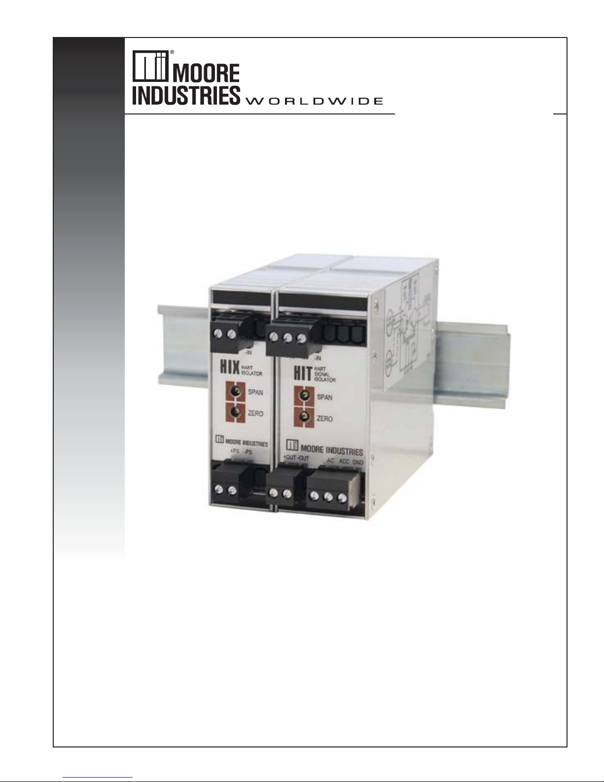
Introduction
The Moore Industries’ 2‑wire, loop powered HIX
HART® Isolator, and its 4‑wire, mains powered
variant, the HIT, are compact, DIN‑rail mounted “loop
add‑ons”. They both are used to break the common
electrical (galvanic) path between a HART transmitter
and one or more receiving devices in a process
instrumentation loop.
About this Manual
Wherever you see a “WARNING”, “Caution” or “Note”
pay particular attention.
WARNING
could injure the operator.
Caution ‑ Hazardous procedure or condition that could
damage or destroy the unit.
‑ Hazardous procedure or condition that
Inputs and Outputs
Input to both the HIX and HIT is HART standard
4‑20mA with digital data superimposed. Both isolators
“pass” the conditioned HART signal through from
transmitter to receiver, and from receiver back to
transmitter. This “signal passing” is operationally
transparent to devices on either end of the loop.
Note:
The HIX and HIT are not HART-addressable
devices. They are “invisible” to the other HART
devices on the loop.
Transmitter Excitation
The 4‑wire HIT is also capable of providing power to
the transmitter it is isolating by virtue of its standard,
24V excitation output.
Note ‑ Information that is helpful for a procedure,
condition, or operation of the unit.
HIT/HIX Description
The HIT and the HIX:
· Safeguard I/O cards from surges, spikes
and transients. Add the 500Vrms isolating
capability of a HART Isolator to a loop to
break the common (galvanic) path that can
pass dangerous overloads from DCS to HART
transmitter to PLC and vice‑versa. This
hazard is common—even when a transmitter
and DCS are supposedly “isolated” already.
· “Isolate” areas of an application. Ease
maintenance complications by using the
4‑wire HIT to maintain secondary loop
integrity while the primary HART master is
down for maintenance.
· Facilitate the “Sharing” of one HART
output—safely—with a secondary control or
recording device.
Power
The HIX is a 2‑wire isolator, drawing power from the
output leg of the loop (typically, the secondary DCS,
PLC, or ESS).
The HIT is a 4‑wire unit. It can be ordered in
congurations that draw power from either external
DC or external AC sources.
Moore Industries offers a complete line of instrument
power supplies ideal for use with the HIT. Ask your
local Interface Solutions Expert for information.
Housing
Both the HIX and HIT are housed in aluminum
DIN‑style housings. Older versions of the product
are housed in high‑impact, thermoplastic cases. The
compact housing styles can be mounted on either
G‑type DIN‑rail or Top Hat DIN‑style rail.
· Eliminate “Bucking” power supply
problems. Whenever more than one
4‑wire device provides power to the loop,
each power source (typically grounded with
differing potentials) vies for control. This
can cause both HART and analog signals to
uctuate, adversely affecting loop reliability
and accuracy.
2 The Interface Solution Experts
1
HART is a registered trademark of the HART Communication Foundation.
Page 3
4-wire/2-wire HART® Isolators
HIT/HIX
Specifications
Performance
Accuracy: ±0.1% of span
Stability: ±0.2% of
reading per year
Isolation:
HIX: 500Vrms between
Input, Output and Case;
HIT: 500Vrms Between
Input, Output, Case and
Power
Tested To:
HIX: 1500Vrms between
Input, Output and Case for
1 minute;
HIT: 1500Vrms between
Input, Output, Case and
DC Power for 1 minute
(2300Vrms from AC Power
to Input, Output and Case
for 1 minute)
Common Mode
Rejection:
Exceeds 95dB at 60Hz
with a limit of 1500Vrms
Performance
(continued)
Input Impedance:
250 ohms nominal, 100
ohms with -IZ100 option
Input Overrange
Protection:
250% of full scale
Output Current
Limiting: 25mA typical;
30mA maximum
Broken Wire Input:
Output driven <=3mA for
HIX; <=1mA for HIT
TX Power Supply:
24Vdc,±10% @ 24mA
(regulated)
Ripple: <10mV for HIX &
HIT DC power and
<35mV for HIT AC power
when measured;
Across 250 Ohm Resistor.
Burden: 5V, maximum
Load Capability:
Vs – 12Vdc
20mA
Response Time
(analog output):
100msec maximum to
99% of output
Ambient
Conditions
Adjustments
Weight
Specications and information subject to change without notice.
Temperature Range:
-20°C to +85°C
(-4°F to +185°F)
Effect: ±0.007% of
span/°C typical;
±0.015% of span/°C
maximum
Humidity: 5-95%
non-condensing
RFI/EMI Protection: Less
than +/- 0.1% of span error
when tested at 10V/m @
80-1000Mhz ;20V/m @
80-1000Mhz for -RF option
Type: Front panel pots
Span: ±10%
Zero: ±5%
(non-interactive when
span is set first)
HIT: DC 283g (10 oz), AC
425 g (15 oz)
HIX: 198 g (7 oz)
Ordering Information
Unit Input Output Power Options Housing
Unit Input Output Power Options Housing
HIT
4‑wire,
Line‑(Mains)
Powered,
HART Isolator
with Transmitter
Excitation
HIX
2‑wire,
Loop‑Powered,
HART Isolator
When ordering, specify: Unit / Input / Output / Power / ‑Option [Housing]
Model number examples: HIX / 4‑20MA / 4‑20MA / 12‑42DC / [DIN] and HIT / 4‑20MA / 4‑20MA / 117AC / ‑RF [DIN]
4-20mA
4‑20mA into 250 ohms
with HART digital
data superimposed
4-20mA
4‑20mA into 250 ohms
with HART digital
data superimposed
4-20mA
Isolated, 4‑20mA
into ≤1000 ohms
(with 24Vdc, 117Vac,
or 230Vac power);
HART digital data
superimposed
4-20mA
Isolated, 4‑20mA
into ≤600 ohms
(with 24Vdc power);
HART digital data
superimposed
24DC ±10%
117AC 50/60HZ,
±15%
230AC 50/60HZ,
±15%
2 Watts power
consumption
12-42DC
-RF 20V/M RFI/EMI
Immunity @ 80‑
1000MHz, 1KHz AM
-IZ100 reduces the
input resistance to
100 ohms
-LL keeps the output
from going below
3.3mA when the
input goes to 0mA
-IZ100 reduces the
input resistance
to 100 ohms
DIN Aluminum
DIN‑style housing
mounts on 32mm
G‑type (EN50035) and
35mm Top Hat
(EN50022) rails
FLB Flange bracket with
top/bottom mounting holes
DIN Aluminum
DIN‑style housing
mounts on 32mm
G‑type (EN50035)
and 35mm Top Hat
(EN50022) rails
FLB Flange bracket with
top/bottom mounting holes
The Interface Solution Experts 3
Page 4
4-wire/2-wire HART® Isolators
HIT/HIX
40mm
(1.5 in)
80mm
(3.1 in)
73mm
(2.8 in)
85mm
(3.3 in)
90mm
(3.5 in)
40mm
(1.5 in)
C
L
40mm
(1.5 in)
22mm
(0.8 in)
+IN –IN +IN+TX –IN +DC–DCC
+OUT –OUT
SPAN
ZERO
SPAN
ZERO
+PS –PS
HIX
HIT
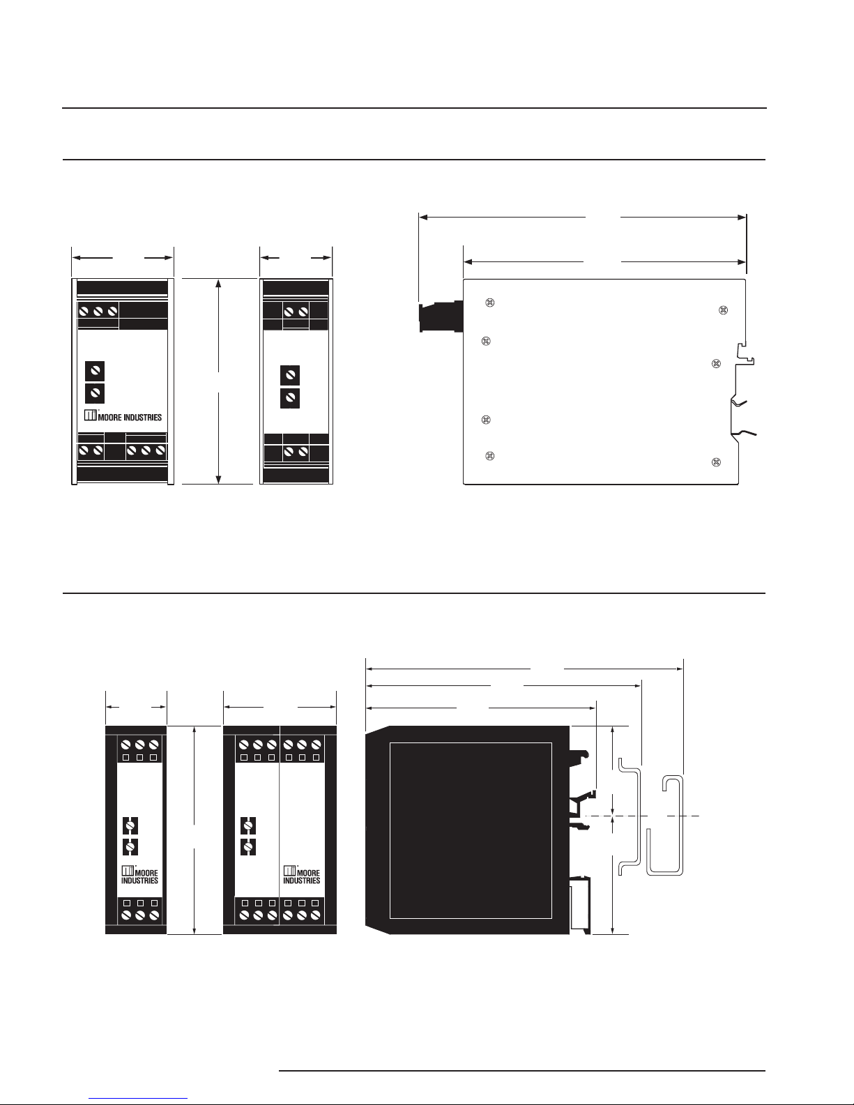
Dimensions
HIX
HART
ISOLATOR
SPAN
ZERO
+PS –PS
25mm
(1.0 in)
36mm
(1.4 in)
80mm
(3.2 in)
110mm
(4.3 in)
130mm
(5.1 in)
+IN -IN
HIT
HART
SIGNAL
ISOLATOR
+IN
SPAN
ZERO
+OUT –OUT
AC ACC GND
–
IN
+TX
Figure 1. Dimensions for Aluminum DIN-Housed HIX and HIT HART Isolators
Figure 2. Dimensions of the older legacy HART Isolator Family of Products in ECD Housings
4 The Interface Solution Experts
Page 5

4-wire/2-wire HART® Isolators
HIT/HIX
Calibration
Current/
Voltage
Calibrator
Adjustable, calibrated to an accuracy of
±0.025% (Moore Industries’ CLC Current Loop
Calibrator or equivalent such as the EDC Model
CRC103 or MV105)
HART Communicator Model 275/375/475
or equivalent. Should be capable of
both reading and simulating a valid HART
signal (and 4-20mA analog signal)
Calibrated, regulated 24Vdc (±10%) source,
nominal, for HIX or dc-powered HIT; calibrated,
regulated 117Vac or 230Vac (±10%) source,
nominal, for ac-powered HIT
250ohm with ±0.01% precision; required only if
using a Voltmeter to calibrate the analog output
from the HIX or HIT (voltage drop across the
precision resistor; 4-20mA=1-5V)
Calibrated to an accuracy of ±0.025%, minimum;
such as Keithley Model 197 or Fluke Model 8840,
8842, or equivalent
Standard (blade) head; head width 3.1mm
(0.125 in), maximum
Device
Specifications
HART
Communicator
Power Supply
Load Resistor
Multimeter
Screwdriver
A
ll referenced product names are the sole property of their
respective manufacturers.
To calibrate the HIX or the HIT, set up the equipment
listed in Table 1 as shown in Figure 3 and Figure 4, as
appropriate.
Procedure
1. Apply the appropriate power to the unit being
calibrated.
Table 1. Calibration Equipment for the HIX and HIT
2. Set the INPUT (current simulator) to 4mA.
3. Adjust the ZERO potentiometer (pot) on the
HIX or HIT front panel until the meter in the
setup reads 1V, ±0.02V.
4. Adjust the INPUT to 20mA.
5. Adjust the SPAN pot on the HIX or HIT front
panel until the meter in the setup reads 5V,
±0.02V.
Note:
HIX and HIT span and zero are non-interactive
as long as zero is set rst.
It is not necessary to repeat steps 3, 4 and 5.
6. Use the HART transmitter simulator to send
data or “a command” to the HART receiver
simulator in the setup.
7. Use the HART receiver to send data or “a
command” to the HART transmitter simulator
in the setup.
8. Repeat steps 2 through 5 while using the
adjustable current source to change the level
of current (staying between 4 and 20mA)
in the setup. Note that the HART trafc is
unaffected by changes in the 4‑20mA owing
through the loop.
The Interface Solution Experts 5
Page 6

4-wire/2-wire HART® Isolators
HIT/HIX
Figure 3. Setting up to Calibrate the HIT
CURRENT
CALIBRATOR
12-42Vdc
POWER
SOURCE
+
250ohm
4-20mA = 1-5V
+
VOLTMETER
+
–
–
–
OPTIONAL
HART
COMMUNICATOR
OPTIONAL
HART
COMMUNICATOR
HIX
HART
ISOLATOR
SPAN
ZERO
+PS –PS
+IN -IN
AC POWER
SOURCE
(CHECK UNIT
MODEL NUMBER)
117Vac
OR
230Vac
OR
CURRENT
CALIBRATOR
OPTIONAL
HART
COMMUNICATOR
+-
HIT
HART
SIGNAL
ISOLATOR
+IN
SPAN
ZERO
+OUT –OUT
DC DCC GND
–IN+TX
250ohm
4-20mA = 1-5V
VOLTMETER
OPTIONAL
HART
COMMUNICATOR
+–
CURRENT
CALIBRATOR
OPTIONAL
HART
COMMUNICATOR
+-
24Vdc
+
–
HIT
HART
SIGNAL
ISOLATOR
+IN
SPAN
ZERO
+OUT –OUT
DC DCC GND
–IN+TX
OPTIONAL
250ohm
4-20mA = 1-5V
VOLTMETER
OPTIONAL
HART
COMMUNICATOR
+–
Note:
Please refer to Fig 2
for legacy ECD housing
terminal designations
Figure 4. Setting up to Calibrate the HIX
6 The Interface Solution Experts
Page 7

4-wire/2-wire HART® Isolators
HIT/HIX
Installation
The HIX and HIT housings accommodate both 32mm,
DIN‑style G‑rail (EN50035) and 35mm Top Hat rail
(EN50022). Figure 1 and Figure 2 on Page 3 show
the dimensions of the housing for each type of isolator.
Electrical Connections
Caution:
Always remove power from the loop
before making any electrical connections.
Note:
Make sure to calibrate the instruments
prior to installation. Also, install all instruments in
their intended application and on their rail before
making any electrical connections. Allow enough
room for pivoting instruments vertically on the rail for
removal in applications involving multiple banks of
HIXs and/or HITs.
Recommended Ground Wiring
Practices
Moore Industries recommends the following ground
wiring practices:
• AnyMooreIndustriesproductinametalcase
or housing should be grounded.
• Theprotectiveearthconductormustbe
connected to a system safety earth ground
before making other connections.
• Allinputsignalsto,andoutputsignals
from, Moore Industries’ products should be
wired using a shielded, twisted pair wiring
technique. Shields should be connected to an
earth or safety ground.
Area Isolation
Figure 5 shows the connections for using an HIX
Isolator to provide area isolation for a secondary
HART master or receiver.
• Forthebestshielding,theshieldshouldbe
run all the way from the signal source to the
receiving device. (see Note below)
• Themaximumlengthofunshieldedinputand
output signal wiring should be 2 inches.
Note:
Some of Moore Industries’ instruments can be
classified as receivers (IPT2, IPX2, etc.) and some
can be classified as transmitters (TRX, TRY, etc.)
while some are both a receiver and a transmitter
(SPA2, HIM, etc). Hence, your shield ground
connections should be appropriate for the type
of signal line being shielded. The shield should
be grounded at the receiver and not at the signal
source.
The Interface Solution Experts 7
Page 8

4-wire/2-wire HART® Isolators
HIT/HIX
CE Conformity
Installation of any Moore Industries’ products that
carry the CE marking must adhere to the guidelines in
the Recommended Ground Wiring Practices section in
order to meet the EN 61326 requirements set forth in
the applicable EMC directive.
WARNING:
If this unit is used in a manner not specied by
Moore Industries, the protection provided by the
equipment may be impaired.
Installation Category
All terminals are rated CAT II, except for terminals with
the ‑RF option. These terminals are rated CAT I.
Equipment Ratings
The HIT does not generate hazardous voltages,
rather, it provides a 4‑20mA current input a 4‑20mA
output. Products connected to the HIT should be
designed to receive these inputs.
Supply Wiring
All power connections should be made with 14 or 16
AWG (0.083mm or 0.064mm) wire.
Switches and Circuit Breakers
A switch or circuit breaker must be wired in series
with the AC power conductors. The switch or circuit
breaker used must be located within three meters of
the unit.
The circuit breaker or switch will only remove power to
the unit, hazardous voltages may still be connected to
other terminals on the unit.
WARNING:
Terminals on this unit may be connected to
hazardous voltages. Before making ANY
connections to this unit, ALL hazardous voltages
must be de-energized.
The end of each conductor should be stripped no
more than 8mm. The end of the stripped wire should
be tinned with solder, or inserted into a ferrule and
crimped before being placed into a terminal block.
Conductors connected to screw‑type connections
should have a ring‑ or spade‑lug crimped onto the
wire end.
8 The Interface Solution Experts
Page 9

4-wire/2-wire HART® Isolators
HIT/HIX
Smart
HART
Transmitter
(Loop-powered)
Primary
HART
Master
(e.g., DCS,
PLC, etc.)
–
+
+
–
Secondary
HART
Master
(e.g., Recorder,
Emergency Shutdown
System, etc.)
4-20mA + HART
12 to 24Vdc
Power
OPTIONAL
HART
COMMUNICATOR
OPTIONAL
HART
COMMUNICATOR
4-20mA + HART
+– –
+
HIX
HART
ISOLATOR
+IN -IN
SPAN
ZERO
+PS –PS
Preventing Power Supply “Bucking”
Figure 5 shows how the HIX can be used to
overcome trouble with power supplies competing
to provide voltage to the HART transmitter. Often,
when a loop consists of several devices drawing
power from separate sources, disparate ground
potentials between these sources cause a “bucking”
phenomenon that can cause current skewing. By
adding a HIX (or HIT) to such loops, this problem is
eliminated.
Figure 5. Using the HIX to “Isolate” a Secondary HART Master.
Solving 4-Wire Transmitter Problems
Figure 6 shows how to use the 4‑Wire HIT to
provide the same kind of power supply isolation in
applications that call for the use of 4‑wire transmitters
The Interface Solution Experts 9
Page 10

4-wire/2-wire HART® Isolators
HIT/HIX
Figure 6. Connecting the HIT in an Application
117
or
230Vac
HIT
HART
SIGNAL
ISOLATOR
+IN
SPAN
ZERO
+OUT –OUT
DC DCC GND
–
IN
+TX
Primary
HART
Master
(e.g., DCS,
PLC, etc.)
+ –
OPTIONAL
HART
COMMUNICATOR
4-20mA + HART
HIT
HART
SIGNAL
ISOLATOR
+IN
SPAN
ZERO
+OUT –OUT
DC DCC GND
–
IN
+TX
Smart
HART
Transmitter
(Externally-powered)
+
–
4-20mA + HART
OPTIONAL
HART
COMMUNICATOR
+
–
24Vdc
Power
10 The Interface Solution Experts
Page 11

4-wire/2-wire HART® Isolators
HIT/HIX
Using -TX to Stop “Bucking”
117
or
230Vac
HIT
HART
SIGNAL
ISOLATOR
+IN
SPAN
ZERO
+OUT –OUT
DC DCC GND
–
IN
+TX
Smart
HART
Transmitter
(Loop-powered)
+
–
4-20mA + HART
OPTIONAL
HART
COMMUNICATOR
HIT
HART
SIGNAL
ISOLATOR
+IN
SPAN
ZERO
+OUT –OUT
DC DCC GND
–
IN
+TX
Primary
HART
Master
(e.g., DCS,
PLC, etc.)
+ –
OPTIONAL
HART
COMMUNICATOR
4-20mA + HART
+
–
24Vdc
Power
Another method of preventing competing power
supplies from causing loop problems incorporates
the HIT’s ‑TX option. Figure 7 shows how to hookup
up the 4‑wire HIT to power the HART transmitter.
This conguration not only solves the bucking power
supply problem. It also saves the cost of an additional
supply.
Figure 7. Using the HIT with TX to combat Power Supply Bucking.
When installing any Moore Industries product,
always follow all local regulations and standards
for grounding, shielding, and safety. The following
grounding and wiring practices must be followed for
HIX in order for the unit(s) to meet the requirements
set forth in EMC standard EN61326.
The Interface Solution Experts 11
Page 12

RETURN PROCEDURES
United States • info@miinet.com
Tel: (818) 894-7111 • FAX: (818) 891-2816
Australia • sales@mooreind.com.au
Tel: (02) 8536-7200 • FAX: (02) 9525-7296
Belgium • info@mooreind.be
Tel: 03/448.10.18 • FAX: 03/440.17.97
The Netherlands • sales@mooreind.nl
Tel: (0)344-617971 • FAX: (0)344-615920
China • sales@mooreind.sh.cn
Tel: 86-21-62491499 • FAX: 86-21-62490635
United Kingdom • sales@mooreind.com
Tel: 01293 514488 • FAX: 01293 536852
To return equipment to Moore Industries for repair, follow these four steps:
1. Call Moore Industries and request a Returned Material Authorization (RMA) number.
Warranty Repair –
If you are unsure if your unit is still under warranty, we can use the unit’s serial number
to verify the warranty status for you over the phone. Be sure to include the RMA
number on all documentation.
Non‑Warranty Repair –
If your unit is out of warranty, be prepared to give us a Purchase Order number when
you call. In most cases, we will be able to quote you the repair costs at that time.
The repair price you are quoted will be a “Not To Exceed” price, which means that the
actual repair costs may be less than the quote. Be sure to include the RMA number on
all documentation.
2. Provide us with the following documentation:
a) A note listing the symptoms that indicate the unit needs repair
b) Complete shipping information for return of the equipment after repair
c) The name and phone number of the person to contact if questions arise at the factory
3. Use sufcient packing material and carefully pack the equipment in a sturdy shipping con‑
tainer.
4. Ship the equipment to the Moore Industries location nearest you.
The returned equipment will be inspected and tested at the factory. A Moore Industries rep‑
resentative will contact the person designated on your documentation if more information is
needed. The repaired equipment, or its replacement, will be returned to you in accordance
with the shipping instructions furnished in your documentation.
WARRANTY DISCLAIMER
THE COMPANY MAKES NO EXPRESS, IMPLIED OR STATUTORY WARRANTIES (INCLUDING ANY WARRANTY OF MERCHANTABILITY OR
OF FITNESS FOR A PARTICULAR PURPOSE) WITH RESPECT TO ANY
GOODS OR SERVICES SOLD BY THE COMPANY. THE COMPANY DISCLAIMS ALL WARRANTIES ARISING FROM ANY COURSE OF DEALING
OR TRADE USAGE, AND ANY BUYER OF GOODS OR SERVICES FROM
THE COMPANY ACKNOWLEDGES THAT THERE ARE NO WARRANTIES
IMPLIED BY CUSTOM OR USAGE IN THE TRADE OF THE BUYER AND
OF THE COMPANY, AND THAT ANY PRIOR DEALINGS OF THE BUYER
WITH THE COMPANY DO NOT IMPLY THAT THE COMPANY WARRANTS
THE GOODS OR SERVICES IN ANY WAY.
ANY BUYER OF GOODS OR SERVICES FROM THE COMPANY
AGREES WITH THE COMPANY THAT THE SOLE AND EXCLUSIVE REMEDIES FOR BREACH OF ANY WARRANTY CONCERNING THE GOODS OR
SERVICES SHALL BE FOR THE COMPANY, AT ITS OPTION, TO REPAIR
OR REPLACE THE GOODS OR SERVICES OR REFUND THE PURCHASE
PRICE. THE COMPANY SHALL IN NO EVENT BE LIABLE FOR ANY CONSEQUENTIAL OR INCIDENTAL DAMAGES EVEN IF THE COMPANY FAILS
IN ANY ATTEMPT TO REMEDY DEFECTS IN THE GOODS OR SERVICES
, BUT IN SUCH CASE THE BUYER SHALL BE ENTITLED TO NO MORE
THAN A REFUND OF ALL MONIES PAID TO THE COMPANY BY THE BUYER
FOR PURCHASE OF THE GOODS OR SERVICES.
ANY CAUSE OF ACTION FOR BREACH OF ANY WARRANTY BY
THE COMPANY SHALL BE BARRED UNLESS THE COMPANY RECEIVES FROM THE BUYER A WRITTEN NOTICE OF THE ALLEGED
DEFECT OR BREACH WITHIN TEN DAYS FROM THE EARLIEST DATE
ON WHICH THE BUYER COULD REASONABLY HAVE DISCOVERED
THE ALLEGED DEFECT OR BREACH, AND NO ACTION FOR THE
BREACH OF ANY WARRANTY SHALL BE COMMENCED BY THE
BUYER ANY LATER THAN TWELVE MONTHS FROM THE EARLIEST
DATE ON WHICH THE BUYER COULD REASONABLY HAVE DISCOVERED THE ALLEGED DEFECT OR BREACH.
RETURN POLICY
For a period of thirty-six (36) months from the date of shipment, and under
normal conditions of use and service, Moore Industries (“The Company”)
will at its option replace, repair or refund the purchase price for any of its
manufactured products found, upon return to the Company (transportation
charges prepaid and otherwise in accordance with the return procedures
established by The Company), to be defective in material or workmanship.
This policy extends to the original Buyer only and not to Buyer’s customers
or the users of Buyer’s products, unless Buyer is an engineering contractor
in which case the policy shall extend to Buyer’s immediate customer only.
This policy shall not apply if the product has been subject to alteration,
misuse, accident, neglect or improper application, installation, or operation.
THE COMPANY SHALL IN NO EVENT BE LIABLE FOR ANY INCIDENTAL
OR CONSEQUENTIAL DAMAGES.
© 2014 Moore Industries‑International, Inc.
Specications and Information subject to change without notice.
 Loading...