

Moore Industries Hawke TRUNKGUARD TG300, Hawke TRUNKGUARD Installation Manual
May 2016
920091D
TG300
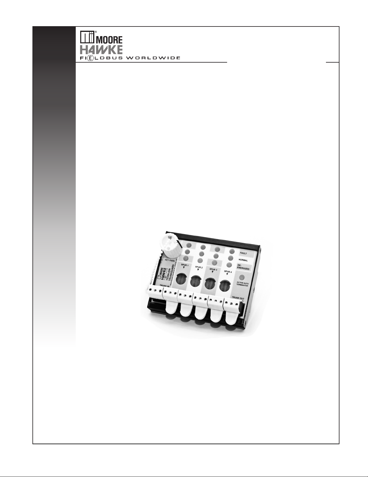
TRUNKGUARD™ Series Fieldbus Device Couplers
(Zone 1 Locations)
TRUNKGUARD™ Series Fieldbus Device Couplers
(Zone 1 Locations)
TG300

Table of Contents
Introduction ............................................................................................................................................. 3
About this Manual ............................................................................................................ 3
DIN Units
Device Coupler Enclosures
.......................................................................................................................... 3
.............................................................................................. 3
Specifications ................................................................................................. 4
Dimensions
Installation
Wiring Connections
Device Coupler Hook-Up .................................................................................................6
DISCONN Key
Recommended Ground Wiring Practices
CE Conformity
..................................................................................................... 4
....................................................................................................... 6
........................................................................................ 6
.................................................................................................................. 7
......................................................................... 7
.................................................................................................................. 8
Testing and Troubleshooting ......................................................................... 8
Operation
Maintenance ..................................................................................................................... 9
......................................................................................................... 9
Customer Support .......................................................................................... 9
Control Drawing
............................................................................................ 11

TRUNKGUARD™ Series Fieldbus Device Couplers
(Zone 1 Locations)
TG300
Introduction
Device Couplers provide easy and practical
mechanisms for implementing fieldbus systems.
TRUNKGUARD Series 300 Device Couplers (TG300)
simplify the use of fieldbus devices in Zone 1 by
allowing “live” access for maintenance and eliminating
the need for Exd junction boxes.
The TG300 Series offers our patented Automatic
Segment Termination feature and a key-operated
magnetic interlock which permits one spur at a time to
be de-energized and worked on without shutting down
the entire segment.
TRUNKGUARD Device Couplers provide electronic
and fully auto-resetting spur short-circuit protection
that prevents a segment failure that maybe caused by
a short circuit to any field device. Utilizing a unique
“Fold-Back” technique, any spur that attempts to draw
more than 48mA is automatically switched off and not
permitted any current flow until the fault is removed.
With removal of the spur short circuit, TRUNKGUARD
automatically reconnects the spur to the fieldbus
segment within 20 microseconds.
The Automatic Segment Termination feature
eliminates segment failure from under or over
termination which is generally the most common
cause for delay in starting up fieldbus projects. The
auto-terminator also assures that local parts of a
segment will continue to function even if there is a
downstream cable break.
DIN Units
TG300-DIN units are designed to fit onto a 32mm
(EN50035) G-type and 35mm (EN50022) Top Hat
DIN-rail and may be mounted at any angle and in
such a way as to allow easy access to terminal
receptacles and to keep LEDs visible. These units are
not weatherproof and outdoor placement will require
an external enclosure. Any enclosure which meets
the requirements of the location in relation to electrical
and mechanical safety may be used.
For Zone 1 applications an external enclosure is
required. The enclosure and glands must be certified
for increased safety and suitable for Zone 1 use,
IP64 protection minimum. All MooreHawke TG300
enclosures are suitable for Zone 1.
Device Coupler Enclosures
Standard enclosures are available in GRP (Glass
Reinforced Polyester with side-entry cable glands).
These enclosures provide IP66/NEMA Type 4X
protection.
Standard cable glands are nickel-plated brass, and
can be ordered for use with un-armored or armored
cable. Compound seal glands (for cable with inter-core
spaces, i.e., unfilled cable), and quick connect plugs
and sockets are also available. Field devices are
individually connected directly to terminals via spur
cables through a variety of cable gland options.
About this Manual
Wherever you see a “Note”, “Caution” or “WARNING”
pay particular attention.
WARNING - Hazardous procedure or condition that
could injure the operator.
Caution - Hazardous procedure or condition that could
damage or destroy the unit.
Note - Information that is helpful for a procedure,
condition, or operation of the unit.
Installation
The enclosure should be mounted to a flat surface
using the internal mounting holes or via external
3
TRUNKGUARD™ Series Fieldbus Device Couplers
(Zone 1 Locations)
TG300
FAULT
NORMAL
DEENERGISED
ACTIVE AUTO
TERMINATOR
KEY PARK
+-S+-S+-S+-S+-S+-S
TRUNK IN
TRUNK OUT
SPUR 4
SPUR 3SPUR 2SPUR 1
Moore Inductries-International, Inc., CA 91343, USA
G
TG304-DIN
TRUNKGUARD
FAULT
NORMAL
DEENERGISED
ACTIVE AUTO
TERMINATOR
+-S+-S
TRUNK OUT
SPUR 8
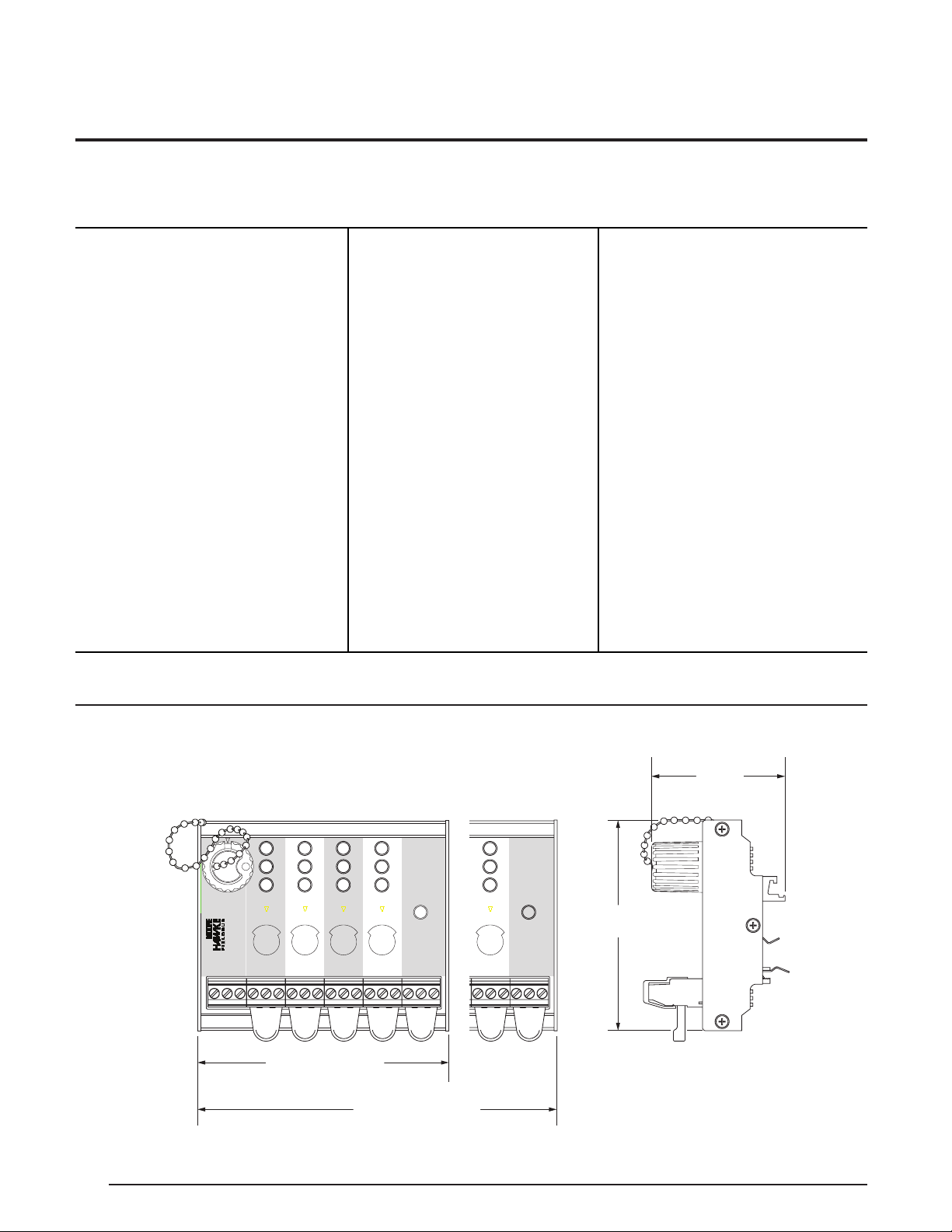
4-Spur: 98mm (3.85 in)
8-Spur: 178mm (7.03 in)
82mm
(3.23 in)
52mm
(2.04 in)
Specifications
Communications
FOUNDATION
Performance
fieldbus™ H1 and
PROFIBUS PA
Performance
Supply Voltage:
10 to 32Vdc
Maximum Segment
Current: 800mA
Maximum Quiescent
Current:
TG304: 13mA@32V
5mA@16VFB
;
FB
TG308: 23mA@32VFB;
10mA@16V
* 3mA less with -MT option
FB
Maximum Spur Output
Current: I
Spur Short Circuit Load:
=5mA (32V), 3mA (16V)
I
Ssc
Spur Voltage Drop:
=48mA
Slim
0.7V@20mA
Maximum Voltage Drop
Trunk IN to OUT: 0.7V
Terminator: 100Ω/1µF
(Internal Automatic
Segment Termination is
standard; For manual
*Auto-terminator function not applicable with -MT option.
(continued)
Indicators
Terminals
termination, specify
the -MT option with
the MooreHawke
model number (e.g.
TG308-DIN-MT). Also
separately specify a
TRK-TERM Trunk
Terminator for mounting
on the final device
coupler in the segment.)
Spur: GREEN (normal)
RED (fault)
YELLOW
(de-energized)
Auto-Terminator:
YELLOW LED is ON
when auto-termination
is activated
Type: EEx e approved
terminals with IP30
shrouds and fillers
Wire Size: Handles
sizes between
0.8-2.5mm
2
/12-24AWG
Cable Glands
(Device
Couplers with
Enclosures)
Ambient
Conditions
Type:
Armored/Unarmored
Material:
Nickel-plated brass
Operating:
-40°C to +70°C
(-40°F to +158°F)
Storage:
-40°C to +85°C
(-40°F to +185°F)
Relative Humidity:
0-95%,
non-condensing
Surge Protection:
EN61326, EN61000-4-5
1KV (1.2/50µsec)
RFI/EMI Immunity:
10V/m@80-1000MHz,
1kHz AM (IEC61326)
Vibration:
(EN 60068-2-6): 1g max
acceleration,10-150Hz
Shock:
(EN 60068-2-27): 15g
max. acceleration, 11ms
Figure 1. DIN-Rail Mounting Installation Dimensions
4
 Loading...