

Page 1
May 2016
920091D
TG300
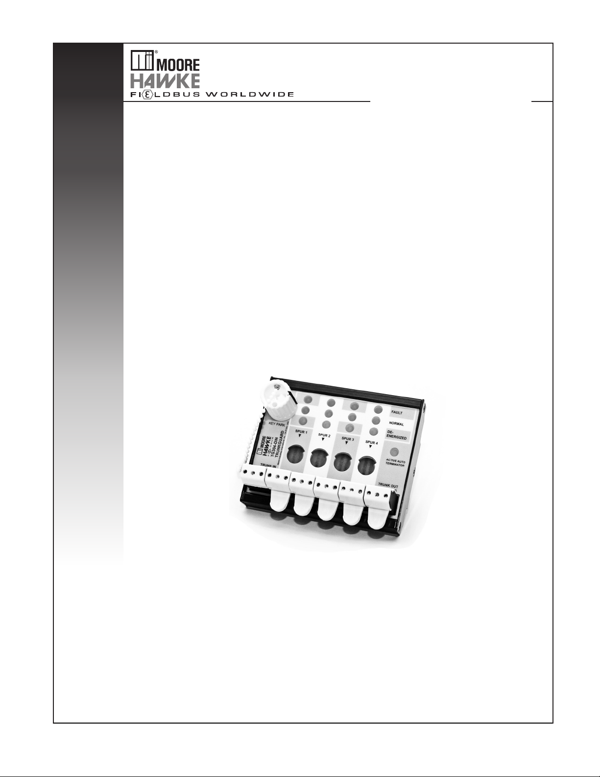
TRUNKGUARD™ Series Fieldbus Device Couplers
(Zone 1 Locations)
TRUNKGUARD™ Series Fieldbus Device Couplers
(Zone 1 Locations)
TG300
Page 2

Table of Contents
Introduction ............................................................................................................................................. 3
About this Manual ............................................................................................................ 3
DIN Units
Device Coupler Enclosures
.......................................................................................................................... 3
.............................................................................................. 3
Specifications ................................................................................................. 4
Dimensions
Installation
Wiring Connections
Device Coupler Hook-Up .................................................................................................6
DISCONN Key
Recommended Ground Wiring Practices
CE Conformity
..................................................................................................... 4
....................................................................................................... 6
........................................................................................ 6
.................................................................................................................. 7
......................................................................... 7
.................................................................................................................. 8
Testing and Troubleshooting ......................................................................... 8
Operation
Maintenance ..................................................................................................................... 9
......................................................................................................... 9
Customer Support .......................................................................................... 9
Control Drawing
............................................................................................ 11
Page 3

TRUNKGUARD™ Series Fieldbus Device Couplers
(Zone 1 Locations)
TG300
Introduction
Device Couplers provide easy and practical
mechanisms for implementing fieldbus systems.
TRUNKGUARD Series 300 Device Couplers (TG300)
simplify the use of fieldbus devices in Zone 1 by
allowing “live” access for maintenance and eliminating
the need for Exd junction boxes.
The TG300 Series offers our patented Automatic
Segment Termination feature and a key-operated
magnetic interlock which permits one spur at a time to
be de-energized and worked on without shutting down
the entire segment.
TRUNKGUARD Device Couplers provide electronic
and fully auto-resetting spur short-circuit protection
that prevents a segment failure that maybe caused by
a short circuit to any field device. Utilizing a unique
“Fold-Back” technique, any spur that attempts to draw
more than 48mA is automatically switched off and not
permitted any current flow until the fault is removed.
With removal of the spur short circuit, TRUNKGUARD
automatically reconnects the spur to the fieldbus
segment within 20 microseconds.
The Automatic Segment Termination feature
eliminates segment failure from under or over
termination which is generally the most common
cause for delay in starting up fieldbus projects. The
auto-terminator also assures that local parts of a
segment will continue to function even if there is a
downstream cable break.
DIN Units
TG300-DIN units are designed to fit onto a 32mm
(EN50035) G-type and 35mm (EN50022) Top Hat
DIN-rail and may be mounted at any angle and in
such a way as to allow easy access to terminal
receptacles and to keep LEDs visible. These units are
not weatherproof and outdoor placement will require
an external enclosure. Any enclosure which meets
the requirements of the location in relation to electrical
and mechanical safety may be used.
For Zone 1 applications an external enclosure is
required. The enclosure and glands must be certified
for increased safety and suitable for Zone 1 use,
IP64 protection minimum. All MooreHawke TG300
enclosures are suitable for Zone 1.
Device Coupler Enclosures
Standard enclosures are available in GRP (Glass
Reinforced Polyester with side-entry cable glands).
These enclosures provide IP66/NEMA Type 4X
protection.
Standard cable glands are nickel-plated brass, and
can be ordered for use with un-armored or armored
cable. Compound seal glands (for cable with inter-core
spaces, i.e., unfilled cable), and quick connect plugs
and sockets are also available. Field devices are
individually connected directly to terminals via spur
cables through a variety of cable gland options.
About this Manual
Wherever you see a “Note”, “Caution” or “WARNING”
pay particular attention.
WARNING - Hazardous procedure or condition that
could injure the operator.
Caution - Hazardous procedure or condition that could
damage or destroy the unit.
Note - Information that is helpful for a procedure,
condition, or operation of the unit.
Installation
The enclosure should be mounted to a flat surface
using the internal mounting holes or via external
3
Page 4
TRUNKGUARD™ Series Fieldbus Device Couplers
(Zone 1 Locations)
TG300
FAULT
NORMAL
DEENERGISED
ACTIVE AUTO
TERMINATOR
KEY PARK
+-S+-S+-S+-S+-S+-S
TRUNK IN
TRUNK OUT
SPUR 4
SPUR 3SPUR 2SPUR 1
Moore Inductries-International, Inc., CA 91343, USA
G
TG304-DIN
TRUNKGUARD
FAULT
NORMAL
DEENERGISED
ACTIVE AUTO
TERMINATOR
+-S+-S
TRUNK OUT
SPUR 8
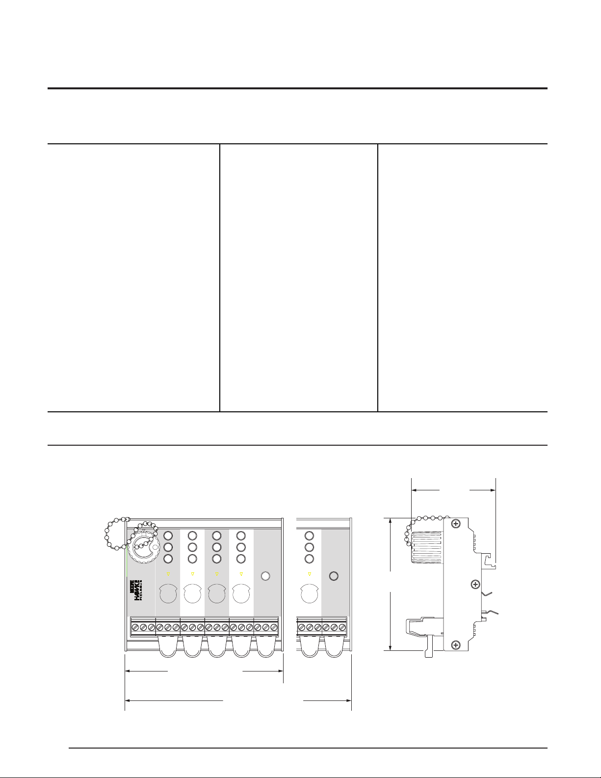
4-Spur: 98mm (3.85 in)
8-Spur: 178mm (7.03 in)
82mm
(3.23 in)
52mm
(2.04 in)
Specifications
Communications
FOUNDATION
Performance
fieldbus™ H1 and
PROFIBUS PA
Performance
Supply Voltage:
10 to 32Vdc
Maximum Segment
Current: 800mA
Maximum Quiescent
Current:
TG304: 13mA@32V
5mA@16VFB
;
FB
TG308: 23mA@32VFB;
10mA@16V
* 3mA less with -MT option
FB
Maximum Spur Output
Current: I
Spur Short Circuit Load:
=5mA (32V), 3mA (16V)
I
Ssc
Spur Voltage Drop:
=48mA
Slim
0.7V@20mA
Maximum Voltage Drop
Trunk IN to OUT: 0.7V
Terminator: 100Ω/1µF
(Internal Automatic
Segment Termination is
standard; For manual
*Auto-terminator function not applicable with -MT option.
(continued)
Indicators
Terminals
termination, specify
the -MT option with
the MooreHawke
model number (e.g.
TG308-DIN-MT). Also
separately specify a
TRK-TERM Trunk
Terminator for mounting
on the final device
coupler in the segment.)
Spur: GREEN (normal)
RED (fault)
YELLOW
(de-energized)
Auto-Terminator:
YELLOW LED is ON
when auto-termination
is activated
Type: EEx e approved
terminals with IP30
shrouds and fillers
Wire Size: Handles
sizes between
0.8-2.5mm
2
/12-24AWG
Cable Glands
(Device
Couplers with
Enclosures)
Ambient
Conditions
Type:
Armored/Unarmored
Material:
Nickel-plated brass
Operating:
-40°C to +70°C
(-40°F to +158°F)
Storage:
-40°C to +85°C
(-40°F to +185°F)
Relative Humidity:
0-95%,
non-condensing
Surge Protection:
EN61326, EN61000-4-5
1KV (1.2/50µsec)
RFI/EMI Immunity:
10V/m@80-1000MHz,
1kHz AM (IEC61326)
Vibration:
(EN 60068-2-6): 1g max
acceleration,10-150Hz
Shock:
(EN 60068-2-27): 15g
max. acceleration, 11ms
Figure 1. DIN-Rail Mounting Installation Dimensions
4
Page 5

TRUNKGUARD™ Series Fieldbus Device Couplers
(Zone 1 Locations)
TG300
Figure 2. GRP (Glass Reinforced Polyester) Enclosure Installation Dimensions
8-Spur Model
4-Spur Model
OUT
IN
1234
250mm
(9.85 in)
200mm
(7.87 in)
120mm
(4.72 in)
255mm
(10.04 in)
235mm
(9.25 in)
OUT
IN
1234
5678
255mm
(10.04 in)
235mm
(9.25 in)
250mm
(9.85 in)
200mm
(7.87 in)
120mm
(4.72 in)
Shows TG338-B-*
Fitted with M20 glands
(Hawke International 501/UNIV/453)
5
Page 6

TRUNKGUARD™ Series Fieldbus Device Couplers
(Zone 1 Locations)
TG300
KEY PARK
FAULT
NORMAL
DEENERGISED
ACTIVE AUTO
TERMINATOR
+
_
S
+
_
S
+
_
S
+
_
S
+
_
S
+
_
S
SPUR 1 SPUR 2 SPUR 4SPUR 3
Device
Exd
Spur Wiring
120m maximum
TRUNK
IN
TRUNK
OUT
EEx me
IIC
T5
Exe
Enclosure
Exd/e
Cable Glands
Key
*
mounting feet (where supplied), in a location where
the risk of external mechanical damage is minimized.
Cable type and cable glands should be selected in
accordance with the intended Zone of installation.
Cables should be brought to the device coupler in
such a way as to prevent external water from running
into the cable entry position. For cables coming
vertically down to a device coupler, it is good practice
to continue down past the device coupler and return
upwards to the cable entry position. All cables should
be supported within 250mm (9.84 in) of the cable
entry position by a cable tray or other support. This is
particularly important with armored cable.
Once the installation and wiring has been completed,
the terminal covers and shrouds (if removed) must be
replaced and the enclosure should be properly closed
and secured.
LEDs indicate the status of each spur as either
“Normal” (GREEN), “Fault” (RED) or “De-Energized”
(YELLOW). “Normal” shows that the spur has voltage
for device operation and that spur current is within
limits. “Fault” indicates that the short circuit protection
has been activated for that spur.
WARNING:
No access is permitted to TRUNK IN
or TRUNK OUT terminals while the
segment is powered.
Use of the DISCONN Key to physically de-energize an
individual spur, allows wiring activity without affecting
other devices on the segment, even in the hazardous
area. The “De-Energized” (YELLOW) LED can only be
activated if the DISCONN Key interlock has operated
correctly, providing a positive indication of safety for
temporary wiring access. The DISCONN Key can be
locked in position, if required. Wiring terminals have
shrouds and fillers to ensure all live parts are covered
to IP30, and these must be refitted before returning
the unit into service.
Wiring Connections
TG300 units have terminals for either four or eight
hazardous area devices, as well as TRUNK IN and
TRUNK OUT terminals. For multiple TRUNKGUARD
units, TRUNK OUT can be looped into any adjacent
TRUNK IN. Segment termination is automatically
provided by the final active TG300 unit. No additional
or external fieldbus terminator is required.
All wiring connections are made directly to Exe
terminals. Cables should be stripped to expose no
more than 8mm (0.31 in) of conductor and inserted
into bootlace ferrules for full insertion into the terminal
opening so that no conductor remains exposed.
Terminals are originally supplied fitted with non-
conducting shrouds and terminal entry fillers. These
components are designed to prevent accidental
Caution:
contact with live parts, and should be retained
for further use. Unused terminals must have the
shrouds/entry fillers restored before the unit is
*Auto-terminator function not applicable with -MT option.
6
energized in the hazardous area.
Segment connections (TRUNK IN and TRUNK OUT)
Figure 4. Typical TG300 Series Device Coupler Hook-Up
Page 7

TRUNKGUARD™ Series Fieldbus Device Couplers
(Zone 1 Locations)
TG300
may be made only while the trunk is de-energized
or under normal Zone 1 working practices (typically,
under local supervision by gas detectors, etc). Spur
connections can be made while the TG300 unit is
energized only if the DISCONN Key is activated
and only the YELLOW LED is ON for that spur.
Alternatively, the whole segment should be deenergized.
Recommended Ground Wiring Practices
Moore Industries recommends the following ground
wiring practices:
• Any MooreHawke product in a metal case or
housing should be grounded.
If the GREEN LED is ON at the same time as the
YELLOW LED is ON, the segment has not been
de-energized and no wiring work is permitted
without removing power to that segment. If the RED
LED is ON, then follow the steps in the Testing and
Troubleshooting section.
Field devices should be certified/approved for use
in hazardous areas (e.g. EEx d in Zone 1) and
are typically connected using armored, braided or
toughened-sheath cabling. MooreHawke cable glands
are EEx d and EEx e approved, but need to be sized
for the appropriate armored or toughened cable.
Earth continuity plates are provided, bonded to an
external earth stud.
DISCONN Key
The DISCONN Key contains the magnet used
to operate the magnetic interlock which permits
individual fieldbus devices to be de-energized and
worked on without de-powering the entire segment.
You must have the DISCONN Key fully inserted into
the spur receptacle for the spur to be de-energized.
• The protective earth conductor must be
connected to a system safety earth ground
before making any other connections.
• The maximum length of unshielded input and
output signal wiring should be 2 inches.
• Some local electrical codes or facility
practices may require the Shield to be
connected to Ground at more than one
location. Follow proper local guidelines.
Fieldbus segment cable Shields for spurs and
trunks are gathered together in the device coupler
and then wired through the trunk cable to the next
device coupler and eventually to the fieldbus power
conditioner. Single point Grounding is recommended
for segment shields. Grounding of the segment shield
usually occurs at the power conditioner.
7
Page 8

TRUNKGUARD™ Series Fieldbus Device Couplers
(Zone 1 Locations)
TG300
CE Conformity
Then
If
Check polarity of TRUNK IN
Check that voltage at TRUNK IN is >10V
Check for short circuits in the trunk cable
Check that the segment power supply is operating correctly
If
Then
Disconnect that individual spur using DISCONN key
Check for a short circuit on that spur cable
Check for a core-to-shield fault on that spur cable
Locate and repair any spur fault before reconnecting that spur
All LEDs are OFF
Any red LED is
ON
Installation of any Moore Hawke products that
carry CE marking must adhere to the guidelines in
Recommended Ground Wiring Practices section in
order to meet the EN 61326 requirements set forth in
applicable EMC directive.
ATEX Installation Drawing
The installation diagrams located in the back of this
manual must be used to augment the installation
instructions described earlier in this manual for units
that are to operate per ATEX requirements.
Testing and Troubleshooting
Testing of the TG300 series should only be performed
in the safe area. Refer to Table 1 regarding LED
indications of fault conditions.
In the safe area, the following tests may be applied:
1. Apply fieldbus power supply of 10-30Vdc
to TRUNK-IN with no other trunk or spur wiring
connected.
Normal indications include:
GREEN LEDs: ON
YELLOW LEDs: OFF
RED LEDs: OFF
Active Auto Terminator LED: ON*
2. Insert DISCONN Key in to each spur one at a
time, switch key position and check that the YELLOW
LED turns ON, and the GREEN LED turns off.
Remove DISCONN Key and place in Key Park.
3. Check the Auto-Terminator* by putting a load
(1kohm, minimum) across the TRUNK OUT terminals.
The YELLOW LED should turn OFF.
Table 1. LED Indications
8
*Auto-terminator function not applicable with -MT option.
Caution:
Do not short any terminals if power conditioner output
can be more than 800mA.
Page 9

TRUNKGUARD™ Series Fieldbus Device Couplers
(Zone 1 Locations)
TG300
Operation
Each spur has three LEDs indicating the following
states: Normal, Fault and De-Energized.
During normal operation, the GREEN LEDs should be
ON for all spur connections.
If any RED LED(s) are ON, the affected spur(s) have
fault(s) in external wiring or field device(s). Please
refer to the Testing and Troubleshooting section..
Maintenance
The TG300 series contain no user serviceable parts.
Non-functioning units should be returned to Moore
Industries for replacement or repair.
WARNING:
Substitution of components may impair
the device coupler, wiring and field device
suitability for hazardous area applications.
Use the DISCONN Key to de-energize that spur,
remove the wiring and then re-energize it by removing
the DISCONN Key. This spur now has no device
connected, and the GREEN LED should turn ON with
the RED LED turning OFF. Use this to confirm a fault
in the spur wiring or field device.
Segment termination is automatically provided by
the last TG300 unit connected in the segment, and
operation is indicated by a YELLOW LED labeled
Active Auto Terminator*.
Note:
When returning non-functioning units only
the DIN-Rail mounted electronics should be
returned. It is normally prudent to retain the
enclosure, glands, and connectors with their
terminals attached when a device coupler is
changed out in the field.
TG300 enclosures have weatherproof seals on
enclosure lids and on cable glands; these should be
periodically inspected to verify correct operation. Any
significant water entry should be investigated and
corrected in order to prevent malfunction.
In high humidity environments, it may be appropriate
to have enclosure breathers fitted so that internal
condensation does not lead to equipment malfunction.
Customer Support
If service assistance is ever required for an instrument
in your application, refer to the back cover of this
manual for the telephone numbers to MooreHawke
Customer Service Department.
If possible, make a note of the model number of the
unit before calling. For fastest assistance, have the
following available: serial number, job number or
purchase order number.
*Auto-terminator function not applicable with -MT option.
9
Page 10

Page 11

RETURN PROCEDURES
• www.miinet.com
United States • info@miinet.com
Tel: (818) 894-7111 • FAX: (818) 891-2816
Australia • sales@mooreind.com.au
Tel: (02) 8536-7200 • FAX: (02) 9525-7296
Belgium • info@mooreind.be
Tel: 03/448.10.18 • FAX: 03/440.17.97
The Netherlands • sales@mooreind.nl
Tel: (0)344-617971 • FAX: (0)344-615920
China • sales@mooreind.sh.cn
Tel: 86-21-62491499 • FAX: 86-21-62490635
United Kingdom • sales@mooreind.com
Tel: 01293 514488 • FAX: 01293 536852
To return equipment to Moore Industries for repair, follow these four steps:
1. Call Moore Industries and request a Returned Material Authorization (RMA) number.
Warranty Repair –
If you are unsure if your unit is still under warranty, we can use the unit’s serial number
to verify the warranty status for you over the phone. Be sure to include the RMA
number on all documentation.
Non-Warranty Repair –
If your unit is out of warranty, be prepared to give us a Purchase Order number when
you call. In most cases, we will be able to quote you the repair costs at that time.
The repair price you are quoted will be a “Not To Exceed” price, which means that the
actual repair costs may be less than the quote. Be sure to include the RMA number on
all documentation.
2. Provide us with the following documentation:
a) A note listing the symptoms that indicate the unit needs repair
b) Complete shipping information for return of the equipment after repair
c) The name and phone number of the person to contact if questions arise at the factory
3. Use sufficient packing material and carefully pack the equipment in a sturdy shipping
container.
4. Ship the equipment to the Moore Industries location nearest you.
The returned equipment will be inspected and tested at the factory. A Moore Industries
representative will contact the person designated on your documentation if more information
is needed. The repaired equipment, or its replacement, will be returned to you in accordance
with the shipping instructions furnished in your documentation.
WARRANTY DISCLAIMER
THE COMPANY MAKES NO EXPRESS, IMPLIED OR STATUTORY
WARRANTIES (INCLUDING ANY WARRANTY OF MERCHANTABILITY
OR OF FITNESS FOR A PARTICULAR PURPOSE) WITH RESPECT TO
ANY GOODS OR SERVICES SOLD BY THE COMPANY. THE COMPANY
DISCLAIMS ALL WARRANTIES ARISING FROM ANY COURSE OF DEALING
OR TRADE USAGE, AND ANY BUYER OF GOODS OR SERVICES FROM
THE COMPANY ACKNOWLEDGES THAT THERE ARE NO WARRANTIES
IMPLIED BY CUSTOM OR USAGE IN THE TRADE OF THE BUYER AND
OF THE COMPANY, AND THAT ANY PRIOR DEALINGS OF THE BUYER
WITH THE COMPANY DO NOT IMPLY THAT THE COMPANY WARRANTS
THE GOODS OR SERVICES IN ANY WAY.
ANY BUYER OF GOODS OR SERVICES FROM THE COMPANY
AGREES WITH THE COMPANY THAT THE SOLE AND EXCLUSIVE
REMEDIES FOR BREACH OF ANY WARRANTY CONCERNING THE
GOODS OR SERVICES SHALL BE FOR THE COMPANY, AT ITS OPTION,
TO REPAIR OR REPLACE THE GOODS OR SERVICES OR REFUND THE
PURCHASE PRICE. THE COMPANY SHALL IN NO EVENT BE LIABLE
FOR ANY CONSEQUENTIAL OR INCIDENTAL DAMAGES EVEN IF THE
COMPANY FAILS IN ANY ATTEMPT TO REMEDY DEFECTS IN THE GOODS
OR SERVICES , BUT IN SUCH CASE THE BUYER SHALL BE ENTITLED
TO NO MORE THAN A REFUND OF ALL MONIES PAID TO THE COMPANY
BY THE BUYER FOR PURCHASE OF THE GOODS OR SERVICES.
ANY CAUSE OF ACTION FOR BREACH OF ANY WARRANTY
BY THE COMPANY SHALL BE BARRED UNLESS THE COMPANY
RECEIVES FROM THE BUYER A WRITTEN NOTICE OF THE ALLEGED
DEFECT OR BREACH WITHIN TEN DAYS FROM THE EARLIEST DATE
ON WHICH THE BUYER COULD REASONABLY HAVE DISCOVERED
THE ALLEGED DEFECT OR BREACH, AND NO ACTION FOR THE
BREACH OF ANY WARRANTY SHALL BE COMMENCED BY THE BUYER
ANY LATER THAN TWELVE MONTHS FROM THE EARLIEST DATE ON
WHICH THE BUYER COULD REASONABLY HAVE DISCOVERED THE
ALLEGED DEFECT OR BREACH.
RETURN POLICY
For a period of thirty-six (36) months from the date of shipment, and under
normal conditions of use and service, Moore Industries (“The Company”)
will at its option replace, repair or refund the purchase price for any of its
manufactured products found, upon return to the Company (transportation
charges prepaid and otherwise in accordance with the return procedures
established by The Company), to be defective in material or workmanship.
This policy extends to the original Buyer only and not to Buyer’s customers
or the users of Buyer’s products, unless Buyer is an engineering contractor
in which case the policy shall extend to Buyer’s immediate customer only.
This policy shall not apply if the product has been subject to alteration,
misuse, accident, neglect or improper application, installation, or operation.
THE COMPANY SHALL IN NO EVENT BE LIABLE FOR ANY INCIDENTAL
OR CONSEQUENTIAL DAMAGES.
© 2013 Moore Industries-International, Inc.
Specifications and Information subject to change without notice.
 Loading...