

Page 1

May 2016
221-703-00 E
240 Milliamp
DIN-style Power Supply
DPS
240 Milliamp
DIN-style Power Supply
DPS
Page 2
Table of Contents
Introduction 1
Description 1
Calibration 3
Installation 5
Troubleshooting 7
HR.
DELIVERY
48
United States/Canada
TOLL FREE
1-800-999-2900
United Kingdom
FREE PHONE
0800 525107
Australia
TOLL FREE
008 251928
Ask for the STAR Center
16650 Schoenborn Street
Sepulveda, California 91343, U.S.A.
Tel: (818) 894-7111 • Tlx: 65-1322
FAX: (818) 891-3297
CONNECT (MacNet): MIISEPULVEDA
18 Royce Road, Crawley
W. Sussex RH10-2NX, United Kingdom
Tel: 0293 514488 • Tlx: 87667
FAX: 0293 36852
3/18 Resolution Drive, Caringbah
New South Wales 2229, Australia
Tel: (02) 525-9177 • Tlx: 790-75914
FAX: (02) 525-7296
Moore Industries’ STAR Center has a
wide variety of quality instrumentation
in stock and ready to ship.
• Signal Transmitters
• Temperature Transmitters
• P/I and I/P Converters
• Isolators and Converters
• Indicators and Displays
• Alarm Trips
• Integrators and Totalizers
• Power Transducers
• Instrument Power Supplies
• Racks, Rails and Enclosures
Most instruments can be customized
to meet your needs. Even then, you’ll
never have to wait more than a few days.
Moore Industries
CENTER
* Support, Technical Assistance, and Repair (our Quick-Ship Facility)
*
Page 3

DPS
Introduction
The DPS 240 is Moore Industries’ 240 milliamp (mA)
DIN-style Power Supply. It is a highly accurate, adjustable unit, most often used to power 2-wire transmitters. It is also ideal for use with data
communications
modules like Moore Industries’ Link Converter Module
(LCM), or Redundant Link Module (RLM).
Unit features include continuous short circuit and
short-term overload protection, input/output isolation,
and a derated circuit design for added dependability.
This manual contains the description, specifications,
calibration information, and installation procedures for
the DPS 240.
Description
The DPS 240 is a compact unit; particularly wellsuited for use in industrial environments where available installation space is at a premium. It is enclosed
in a standard, DIN-style, aluminum housing designed to be installed on a standard “G-rail” (not included). This rail can then be mounted on a wall, in a
rack, or in a NEMA enclosure. Each DPS 240 is capable of powering twelve 4-20 mA loops.
The front panel of the the unit features potentiometers
for adjustment of voltage and current limit, test jacks
for auxiliary connection of calibration equipment, and
a red LED indicator that lights when dc output is
present.
The terminal blocks, three for input and eight for output, can be set into either the front or rear panel, according to customer specification.
The unit is available in 24- or 42-Vdc output configurations. A potentiometer on the front panel allows for
adjustment of the output ±5.0%.
Input voltage can also be specified by the customer,
and is available set to 117, 220, or 240 Vac, 50/60
Hz.
The equipment specifications for the DPS 240
are listed in table 1.
Serial Number. A complete, serial-number-depen-
dent history is kept on every unit that Moore Industries sells and services. For service information,
provide the factory with the serial number of the unit
that requires
attention. The serial number is stamped on a label,
and affixed to the side panel.
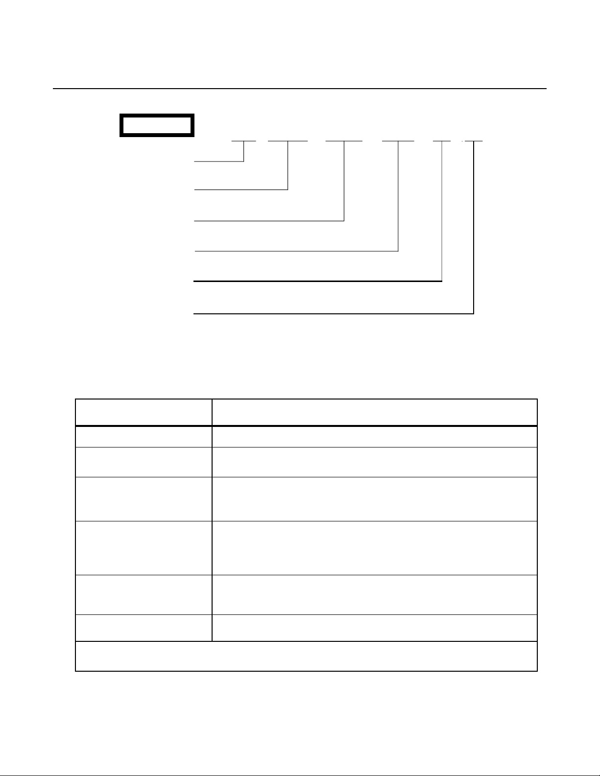
Model Number. Moore Industries’ model numbers
identify the type of instrument, functional characteristics, any options ordered, and the housing type. The
model number reflects the way the unit was configured when it originally left the factory. It is all that is
needed to identify the operational characteristics of
the power supply. The number appears on the same
label as the serial number.
The following example outlines the significance of
each field in a typical DPS 240 model number.
Page 1
Page 4
DPS
EXAMPLE
Unit Type
OutPut Voltage
Current
Power
Options(s)
Housing
DPS / 24VDC / 240 MA / 117AC/ -FA / [DIN]
Table 1. DPS 240 Equipment Specifications
Characteristics
Input Power
Input Frequency
Output
Performance Efficiency
Environmental Conditions
Weight
NOTE: Refer to the Installation Section of this manual for unit dimensions.
Specifications
117, 220, or 240 Vac (factory-configured according to customer requirement)
48 to 62 Hz
Supply Type: Linear
24 or 42 Vdc, 240 mA (factory-configured according to customer requirement),
adjustable ±5.0% with front panel potentiometers
Regulation: 0.5% maximum, low line to high line
70% typical, rated at full load
Load: 1.0% maximum, no load to full load
Ripple: 50 mV peak-to-peak, maximum
Isolation: Input/Output/Unit Housing = 1100 Vrms
Ambient Temperature Operating Range: 0 to +70 °C (+32 to +158 °F)
Effect on Unit: ±0.03% per °C over the range specified
765 grams (1 pound, 11 ounces)
Page 2
Page 5

DPS
Calibration
Each power supply is calibrated and checked at the
factory to ensure proper performance before shipping.
However, output values for each unit should be
checked by the user on-site before the equipment is
placed into service.
Indicators
There is a red LED indicator on the front panel of the
DPS 240, which lights when the unit is producing dc
output. The indicator, labeled “OUTPUT ON”, goes
out if a short circuit, overload, or any other unacceptable condition occurs during operation.
Controls
The unit’s front panel has two multiturn potentiometers labeled “VOLTAGE ADJUST” and “CURRENT
LIMIT”. Voltage adjust allows the user to set dc output to ±5.0% of the rated value. Using the current
limit potentiometer, the user can calibrate the unit so
that the output voltage stays within the specified
range, even when input varies ±10%. This protects
the DPS 240 from possible damage due to overheating.
Refer to table 1 for the equipment specifications of
the DPS 240.
Calibration Equipment
Table 2 lists the equipment required to calibrate the
DPS 240. This equipment must be provided by the
user.
Equipment
Adjustable ac Power Source
Voltmeter
Milliammeter
Variable Power Resistor
Screwdriver, slotted
Table 2. Calibration Equipment
Description
Variac or equivalent; capable of 105-264 Vac output
Accurate to 0.01 millivolt
Accurate to 1.0 milliamp
Powerstat, or equivalent; capable of output load of 175ý
Head measuring less than 2.54 mm (0.1 inch) in width
Page 3
Page 6

DPS
Calibration Setup
Calibration should be performed in a laboratory setting. This will allow the user to control input variables,
and to monitor changes in the output more easily.
Figure 1 depicts the correct calibration setup for the
DPS 240.
Before beginning to the calibration itself, connect the
unit as shown, and set the load to 100 ohms for
24Vdc units, or 175 ohms for 42 Vdc units.
ADJUSTABLE
AC POWER
SOURCE
GND AC ACC
Apply the appropriate ac power to the setup (117, 220,
or 240 Vac). The specifications table and the model
number printed on the serial tag list the acceptable
input power levels for the unit being calibrated.
When power is applied, the front panel “OUTPUT ON”
LED will light, indicating the presence of dc output.
+
VOLTMETER
–
+
MILLIAMMETER
–
GND AC ACC + DC OUT – DC OUT
POWER
DPS
VOLTAGE ADJUST
CURRENT LIMIT
OUTPUT ON
+T
T
SUPPLY
LOAD
Figure 1. DPS 240 Calibration Setup
Page 4
Page 7

DPS
Calibration Procedure
To calibrate the DPS 240:
1. Turn CURRENT LIMIT potentiometer fully clockwise.
2. Vary setting of VOLTAGE ADJUST potentiometer
from fully clockwise to fully counterclockwise.
Note output reading at each extreme. Available
voltage range will equal ±5.0% of unit’s rated output voltage (23.8 to 25.2 Vdc for 24-Vdc models,
or 39.9 to 44.1 Vdc for 42-Vdc models).
3. Use VOLTAGE ADJUST potentiometer to set output voltage to maximum specified for the unit being calibrated, ±10 millivolts (24, or 42 Vdc, as
appropriate).
4. Reset load to 91ý, or until the milliammeter reads
264 mA (+10% of the maximum rated current output for the DPS 240).
5. Turn CURRENT LIMIT potentiometer counterclockwise until output voltage drops to 23.88 Vdc
for 24 Vdc units, or 41.79 Vdc for 42 Vdc units
(99.5% of appropriate nominal output level ).
6. Reset load so that current output is 240 mA.
7. Short the output.
Red “OUTPUT ON” LED on unit’s front panel will
go out.
8. Hold short circuit in place for 1 minute, then remove it. Observe that the LED turns on, and that
output voltage quickly returns to rated nominal,
±10 mV (23.88 Vdc for 24-Vdc units, or 41.79 Vdc
for 42-Vdc units).
9. Remove load. Observe that output voltage drop is
less than 100 mV.
12. Use VOLTAGE ADJUST potentiometer to select
output voltage desired. Disconnect voltmeter from
terminal blocks, and re-connect leads to “+T” and
“–T” test jacks on front panel of DPS 240.
13. Verify that reading at these test jacks is the same
as for terminal block connections.
14. Remove ac input, and dismantle test setup.
The unit is now calibrated and ready to be placed into
service.
Installation
Installing the DPS 240 consists of physically mounting
the device, and then completing the necessary electrical connections.
Mounting
Although the DPS 240 is designed to employ convection cooling, it is advised to mount it on a surface
made of material that can serve as a heat sink. Care
should also be taken to locate the DPS 240 in an area
that is protected from dust, moisture, and corrosive
atmospheres.
Figure 2 shows the outline dimensions of the DPS
240.
To mount the unit, the DIN rail should be positioned so
that the smaller of its two flanges is toward the top
(see figure 2).
Tilt the unit slightly backward, and insert the spring
flanges on the back panel under the top flange of the
DIN rail. Push inward and down until the DPS 240
snaps into place.
10. Re-apply load. Set it so that current output is 240
mA. Note output voltage reading at this setting.
11. Vary input voltage ±10%. Observe that voltage
varies less than 0.5%, low-line to high-line.
To remove the unit, pull outward (from the bottom)
and up.
Page 5
Page 8

DPS
66mm
(2.59 in)
80mm
(3.15 in)
OPTIONAL
ENGRAVED TAG
FOR CUSTOMER I.D.
Figure 2. Outline Dimensions for the DPS 240
Electrical Connections
Figure 3 shows the front panel of the DPS 240 in detail, and depicts its electrical connection in a typical
application.
For information on the Moore Industries products that
typically work with the DPS 240, contact your local
sales representative, or Moore Industries’ Customer
Service Department.
94mm
(3.89 in)
9mm
(0.35 in)
SPRING
FLANGE
93mm
(3.65 in)
103mm
(4.05 in)
32mm
(1.28 in)
TS-32
G-RAIL
15mm
(0.59 in)
strip 5/16 to 3/8 inches of the insulation from the end
of the wire.
To connect the DPS 240, loosen the clamping screw
of the appropriate terminal, and insert the uninsulated
end of the wire into the socket. Tighten the screw
while holding the wire in place. Finally, tag the wire
for identification. Once supplied with the appropriate
ac power, the DPS 240 will begin to operate.
The use of 14-22 AWG insulated copper wire is recommended in connecting the DPS 240 terminals.
To avoid transients and stray pick-ups, it is recommended that twisted conductors be used when running close to other services. To ensure good contact,
Page 6
Page 9

DPS
AC POWRER
SOURCE
117, 220,
OR
240 VAC
GND AC ACC
DPS
VOLTAGE ADJUST
CURRENT LIMIT
OUTPUT ON
T
+
T
+ DC OUT
– DC OUT
POWER
SUPPLY
+
2-WIRE TRANSMITTER
–
+
CURRENT-DRIVEN
DEVICE
–
GND AC ACC + DC OUT – DC OUT
Figure 3. Typical Connection of the DPS 240
Troubleshooting
If a problem develops with the performance of the
DPS 240, use the front panel test jacks to verify the
proper output voltage. The probes should be 2.03 mm
(0.08 in) in diameter, and 12.7 mm (0.50 in) long,
maximum.
Connect a voltmeter to the appropriate test jacks, and
re-adjust the output using the two adjustment potentiometers, VOLTAGE ADJUST and CURRENT LIMIT.
If problems continue, remove and recalibrate the
unit. Refer to the Calibration section of this manual.
Any units found to be performing below specifications should be immediately returned to the factory
for service. Instructions for return of the equipment
are on the back cover of this manual. Customers
may also contact Moore Industries’ Customer Service Department at 1-800-999-2900 for assistance.
Page 7
Page 10

NO TES
Page 11

RETURN PROCEDURES
To return equipment to Moore Industries for repair, follow these four steps:
1. Call Moore Industries and request a Returned Material Authorization (RMA) number.
Warranty Repair –
If you are unsure if your unit is still under warranty, we can use the unit’s serial number
to verify the warranty status for you over the phone. Be sure to include the RMA
number on all documentation.
Non-Warranty Repair –
If your unit is out of warranty, be prepared to give us a Purchase Order number when
you call. In most cases, we will be able to quote you the repair costs at that time.
The repair price you are quoted will be a “Not To Exceed” price, which means that the
actual repair costs may be less than the quote. Be sure to include the RMA number on
all documentation.
2. Provide us with the following documentation:
a) A note listing the symptoms that indicate the unit needs repair
b) Complete shipping information for return of the equipment after repair
c) The name and phone number of the person to contact if questions arise at the factory
3. Use sufficient packing material and carefully pack the equipment in a sturdy shipping
container.
4. Ship the equipment to the Moore Industries location nearest you.
The returned equipment will be inspected and tested at the factory. A Moore Industries
representative will contact the person designated on your documentation if more information is
needed. The repaired equipment, or its replacement, will be returned to you in accordance with
the shipping instructions furnished in your documentation.
WARRANTY DISCLAIMER
THE COMPANY MAKES NO EXPRESS, IMPLIED OR STATUTORY WARRANTIES (INCLUDING ANY WARRANTY OF MERCHANTABILITY OR OF FITNESS
FOR A PARTICULAR PURPOSE) WITH RESPECT TO ANY GOODS OR SERVICES SOLD BY THE COMPANY. THE COMPANY DISCLAIMS ALL WARRANTIES ARISING FROM ANY COURSE OF DEALING OR TRADE USAGE, AND
ANY BUYER OF GOODS OR SERVICES FROM THE COMPANY ACKNOWLEDGES THAT THERE ARE NO WARRANTIES IMPLIED BY CUSTOM OR
USAGE IN THE TRADE OF THE BUYER AND OF THE COMPANY, AND THAT
ANY PRIOR DEALINGS OF THE BUYER WITH THE COMPANY DO NOT IMPLY THAT THE COMPANY WARRANTS THE GOODS OR SERVICES IN ANY
WAY.
ANY BUYER OF GOODS OR SERVICES FROM THE COMPANY AGREES
WITH THE COMPANY THAT THE SOLE AND EXCLUSIVE REMEDIES FOR
BREACH OF ANY WARRANTY CONCERNING THE GOODS OR SERVICES
SHALL BE FOR THE COMPANY, AT ITS OPTION, TO REPAIR OR REPLACE
THE GOODS OR SERVICES OR REFUND THE PURCHASE PRICE. THE
COMPANY SHALL IN NO EVENT BE LIABLE FOR ANY CONSEQUENTIAL OR
INCIDENTAL DAMAGES EVEN IF THE COMPANY FAILS IN ANY ATTEMPT
TO REMEDY DEFECTS IN THE GOODS OR SERVICES , BUT IN SUCH CASE
THE BUYER SHALL BE ENTITLED TO NO MORE THAN A REFUND OF ALL
MONIES PAID TO THE COMPANY BY THE BUYER FOR PURCHASE OF THE
GOODS OR SERVICES.
ANY CAUSE OF ACTION FOR BREACH OF ANY WARRANTY BY THE
COMPANY SHALL BE BARRED UNLESS THE COMPANY RECEIVES
FROM THE BUYER A WRITTEN NOTICE OF THE ALLEGED DEFECT OR
BREACH WITHIN TEN DAYS FROM THE EARLIEST DATE ON WHICH THE
BUYER COULD REASONABLY HAVE DISCOVERED THE ALLEGED DEFECT OR BREACH, AND NO ACTION FOR THE BREACH OF ANY WARRANTY SHALL BE COMMENCED BY THE BUYER ANY LATER THAN
TWELVE MONTHS FROM THE EARLIEST DATE ON WHICH THE BUYER
COULD REASONABLY HAVE DISCOVERED THE ALLEGED DEFECT OR
BREACH.
RETURN POLICY
For a period of thirty-six (36) months from the date of shipment, and under
normal conditions of use and service, Moore Industries ("The Company") will
at its option replace, repair or refund the purchase price for any of its manufactured products found, upon return to the Company (transportation charges
prepaid and otherwise in accordance with the return procedures established
by The Company), to be defective in material or workmanship. This policy
extends to the original Buyer only and not to Buyer's customers or the users
of Buyer's products, unless Buyer is an engineering contractor in which case
the policy shall extend to Buyer's immediate customer only. This policy shall
not apply if the product has been subject to alteration, misuse, accident, neglect or improper application, installation, or operation. THE COMPANY
SHALL IN NO EVENT BE LIABLE FOR ANY INCIDENTAL OR CONSEQUENTIAL DAMAGES.
United States • info@miinet.com
Tel: (818) 894-7111 • FAX: (818) 891-2816
Australia • sales@mooreind.com.au
Tel: (02) 8536-7200 • FAX: (02) 9525-7296
Belgium • info@mooreind.be
Tel: 03/448.10.18 • FAX: 03/440.17.97
Tel: 86-21-62491499 • FAX: 86-21-62490635
The Netherlands • sales@mooreind.nl
Tel: (0)344-617971 • FAX: (0)344-615920
Specifications and Information subject to change without notice.© 2005 Moore Industries-International, Inc.
China • sales@mooreind.sh.cn
United Kingdom • sales@mooreind.com
Tel: 01293 514488 • FAX: 01293 536852
 Loading...