

Page 1
May 2016
192-720-00 C
DIN-style
Direct Current Alarm
DDA
DIN-style
Direct Current Alarm
DDA
Page 2

Table of Contents
Introduction .......................................................................................................1
Description.........................................................................................................1
Specifications ....................................................................................................1
Ordering Information.........................................................................................2
DDA Model Numbers ..........................................................................................................2
Options ...............................................................................................................................2
Calibration..........................................................................................................3
Alarm Terminology .............................................................................................................. 4
DDA Controls ...................................................................................................................... 5
Calibration Setup ................................................................................................................ 8
Calibration Procedures ..................................................................................................... 11
Calibrating a Unit with the DA Option................................................................................ 12
Setting Deadband for AD Equipped Units ......................................................................... 12
Installation ....................................................................................................... 13
Mounting the DDA............................................................................................................. 13
Making the Electrical Connections .................................................................................... 14
Recommended Ground Wiring Practices .......................................................................... 14
CE Conformity...................................................................................................................14
Operation ......................................................................................................... 21
Customer Support........................................................................................... 22
List of Figures and Tables
Figure 1. How the DDA Alarm Operates .......................................................................................... .................... 4
Figure 2. Disassembling the DDA ........................................................................................................................ 5
Figure 3. PC4 Component Locations ................................................................................................................... 6
Figure 4. Calibrating the Single-alarm DDA ......................................................................................................... 8
Figure 5. Calibrating the Dual-alarm DDA ............................................................................................................ 9
Figure 6. Calibrating Single-alarm DDAs with the Transistor Switch Output Option ............................................. 9
Figure 7. Calibrating the Dual-alarm DDA with the Transistor Switch Output Option ......................................... 10
Figure 8. Calibrating the DDA with the Deviation Alarm Option.......................................................................... 10
Figure 9. Dimensions of the DDA ....................................................................................................................... 13
Figure 10. Installing the Single-alarm DDA ........................................................................................................ 15
Figure 11. Installing the Dual-alarm DDA ........................................................................................................... 15
Figure 12. Installing the Single-alarm DDA with the Transistor Switch Output Option ........................................ 16
Figure 13. Installing the Dual-alarm DDA with the Transistor Switch Output Option .......................................... 16
Figure 14. Installing the Dual-alarm DDA with the Double-pole/Single-throw, Normally Open Relays Option ...17
Figure 15. Installing the Dual-alarm DDA with the Double-pole/Single-Throw, Normally Closed Relays Option 18
Figure 16. Installing the Dual-alarm DDA with the Double-pole/Single Throw, Normally Open/Normally Closed
Relays Option ................................................................................................ .................................... 19
Figure 17. Installing the Single-alarm DDA with the Deviation Alarm Option .....................................................19
Figure 18. Installing the Dual-alarm DDA with the Deviation Alarm Option ........................................................ 20
Figure 19. Installing the Single-alarm DDA with the Transmitter Excitation Option ............................................ 20
Figure 20. Installing the Dual-alarm DDA with the Transmitter Excitation Option ............................................... 21
Table 1. Failsafe/Non-failsafe Jumper Settings .................................................................................................... 7
Table 2. High/Low Alarm Jumper Settings ........................................................................................................... 7
Table 3. EU Option Display Range Jumper Settings ............................................................................................ 7
Table 4. Calibration Equipment ............................................................................................................................8
Page 3

Page 1
DDA
Introduction
Moore Industries’ DIN-style Direct Current alarm, the
DDA, accepts all standard process current and voltage inputs and provides an alarm response to input
that falls outside of an adjustable preset limit. The
DDA comes in single- and dual- alarm models. The
dual-alarm model allows two separate trip points to
be configured per module.
This manual contains the information necessary to
calibrate, install, operate, maintain, and troubleshoot
the DDA. It includes a brief unit description, a table
of performance and operational specifications, and
an explanation of Moore Industries’ model number
based product data tracking system.
The following guidelines are used throughout the
manual:
WARNING
could injure the operator.
Caution
could damage or destroy the unit.
Note
condition, or operation of the unit.
– Hazardous procedure or condition that
– Hazardous procedure or condition that
– Information that is helpful for a procedure,
Description
The DDA is a 4-wire, process alarm that is powered
by an external 24 Vdc power source. It accepts standard process current or voltage (factory-set) and responds to a user-adjustable trip point by changing
the output state when the input exceeds the trip point
setting. The output is either a normally-open (NO) or
normally-closed (NC) relay contact-closure (standard), or an opto-isolated, open-collector transistor
(optional).
The DDA is factory-set for single- or dual-alarm
operation. Standard single-alarm units have a
double-pole, double-throw (DPDT) relay output (output A). Standard dual-alarm units have two singlepole, double-throw (SPDT) relay outputs (outputs A
and B).
The standard DDA has a built-in 1.0 percent dead
band. The unit resets when the input signal has
crossed over the trip point on its return to the userselected non-alarm range, and is 1.0 percent of span
beyond the trip point.
The unit housing is a plastic, DIN-style case that can
be mounted on either a DIN-style top-hat rail (standard) or G-rail (optional). Refer to the Installation
Section for housing dimensions.
Specifications
Peformance
Display Accuracy:
±0.1% of input span;
±1 count to include
repeatability,
hysteresis, and
adjustment
resolution
Repeatability: Trip
point repeats within
±0.1% of input span
Dead Band: 1% of
input span (standard)
Signal Response:
-3dB @ 5Hz typical
(low pass)
Alarm Response:
50 milliseconds
standard
Isolation: 500Vac,
input to output to
power
Peformance
(continued)
Ambient
Temperature
Adjustments
RFI/EMI Effect: With field
strengths of 10V/m, at
frequencies of 20-500 Mhz,
unit will not go into alarm
status unless process
variable is within ±1.0% of
trip point
Range: -18°C to 65°C
(0°F to 149°F)
Effect: ±0.018% of span/°C
Front Panel Adjustments
Type: Multiturn
potentiometers
Trip Point(s): Adjust over a
range of -5% to 105% of
span, typical
Input/Trip Point Viewing:
Two or three-position rotary
switch allows selection of
viewing the Input, Trip A, or
Trip B on the integral LCD
Adjustments
(continued)
Indicators
Weight
Internal Adjustments Type:
Multiturn potentiometers
Zero: Adjustable to ±10% of
span
Span: With full scale input,
output is adjustable to 100%,
±10% of span.
Display: 3½ digit LCD
displays either Input, Trip A
setting, or Trip B setting as
determined by rotary switch;
display indicates from -5.0%
to 105% of input span and id
linear with respect to the
input signal
Trip Point: Led(s) on front
panel indicates alarm status
for each trip point ("ON" LED
indicates energized relay)
297 grams (10.5 ounces)
The Interface Solution Experts
Page 4

Page 2
DDA
Ordering Information
Unit Input Output Power Options Housing
Current:
DDA
0-20 mA @25Ω
1-5 mA @100Ω
4-20 mA @25Ω
10-50 mA @10Ω
Voltage @ 1MΩ
0-1V
0-5V
1-5V
0-10V
Alarm Configuration: (High/Low and
Failsafe/Non-Failsafe are jumperselectable)
SH1 Single, High, Failsafe
SH2 Single, High, Non-Failsafe
SL1 Single, Low, Failsafe
SL2 Single, Low, Non-Failsafe
DH1L1 Dual, High/Low, Failsafe
DH2L2 Dual, High/Low, Non-Failsafe
DH1H1 Dual, High/High, Failsafe
DH2H2 Dual, High/High, Non-Failsafe
DL1L1 Dual, Low/Low, Failsafe
DL2L2 Dual, Low/Low, Non-Failsafe
(DPDT relays standard on single alarms,
SPDT relays standard on dual alarms;
relay contacts rated 5A @ 116Vac or
28Vdc or 2A @ 249Vac; all non-inductive
loads, 50/60Hz)
24DC
Accepts
24Vdc,
±10% (1.5
to 2.5 watts
nominal;
3.3 watts
max., with
TX option)
-AD Adjustable Deadband
-AR Alarm Response time delay
-DA Deviation Alarm
-DPSTNO DPST Normally Open
relays (dual alarms)
-DPSTNONC DPST with one
Normally Open and one
Normally Closed contact per
relay (dual alarms)
-EU Indicator displays in
engineering units
-GR Adaptor for mounting on a
DIN (50035-G32) G-rail
-HS Hermetically Sealed relays
-MR Manual Reset
-TSO Transistor Switch Output
-TX 2-wire Transmitter Excita-
tion
DIN
Thermoplastic,
DIN-style rail
(35mm Top Hat
Rail) mount
housing with
removable
terminal blocks.
DDA Model Numbers
To order additional or replacement modules for your
system, refer to the Ordering Information table and
“build” a model number using the information in bold
text. Specify the following in order:
Product / Input / Output / Power / Option
[Housing]
For example, specify:
DDA / 4-20MA / DH1L2 / 24DC / -AR5 [DIN]
Options
The following options are available with the DDA:
AD Option.
adjust the deadband to any value between 1 and 20
percent of span. (Not available with MR Option.)
AR Option.
option which causes the output to react to an alarm
condition after a specified time delay. The available
delays are between 1-30 seconds.
Adjustable Deadband.
Alarm Response delay.
Allows you to
A factory-set
DA Option.
Deviation Alarm.
Accepts input from
two sources and then displays a value that is proportional to the
difference
between the two signals.
When both input signals are equal to each other, the
LCD will display 50.0 percent. This is true regardless of what the actual value of the inputs are, as
long as they are of equal value. If either input signal varies, the proportional difference between the
two values will be added to or subtracted from the
balanced
indication of 50.0 percent that is displayed
on the LCD. (Not available with TX Option.)
DPSTNO Option.
Normally Open relays
DPSTNC Option.
Double-Pole/Single-Throw with
. Requires dual alarms.
DPST Normally Closed relays.
Requires dual alarms.
DPSTNONC Option.
and one normally closed contact per relay.
DPST with one normally open
Requires
dual alarms.
EU Option.
Engineering Units
. Provides userselectable values for display in the range of 0-200
through 0-1999. (Consult factory for engineering
unit values not starting at zero.) This option also allows for changing the position of the decimal point to
any one of three locations.
The Interface Solution Experts
GR Option.
G-Rail.
(EN50035) G-rail.
Adaptor for mounting on a DIN
Page 5

Page 3
DDA
HS Option.
28Vdc non-inductive or 1A @ 120Vac non-inductive,
50/60Hz.
MR Option.
beled “RS” and located on the same terminal strip as
the other alarm output contacts) are provided for
each output. These must be shorted momentarily to
clear an alarm condition. (Non-latching pushbuttons must be supplied by the user. Toggle or latching switches are not recommended because the
alarm cannot go into an alarm state if the RS terminals are permanently closed.) (Not available with
the AD Option.)
Units equipped with the MR option must be
reset manually after input returns to a non-
TSO Option.
an open-collector transistor output instead of the
standard contact closure relay(s). Can switch 60mA
at 60Vdc maximum.
TX Option.
at 25 mA to drive a process loop directly from the
DDA. (Not available with the DA Option or with 1050 mA input units.)
Hermetically sealed
Manual Reset.
Note:
alarm level.
Transistor Switch Output.
Transmitter Excitation.
relays rated 3A @
A pair of terminals (la-
Provides 24 Vdc
Provides
Calibration
Prior to shipment, every DDA is subjected to rigorous testing by our team of skilled technicians. Every product Moore Industries manufactures, sells
and services is guaranteed to meet the strict quality
standards that have become synonymous with our
name.
Before placing your DDA into service, a bench
check of basic operation is recommended to ensure
that the unit hasn’t sustained any damage during
transit, and to set zero and span for your application.
Every unit should be:
• Checked to verify that the appropriate DDA
model has been ordered for the intended
application.
• Connected in a calibration setup and checked
for desired output.
• Adjusted for desired zero and span.
• Checked for proper trip point, TSO output or
relay function.
Even if a unit has been configured to your specifications by the factory (factory calibration), it is a good
idea to perform a simple bench check. The procedures provide a safe means to uncover any unit
damage that may have occurred during shipping,
and offer a familiarization with DDA operation in the
safety of a testing environment, separate from the
intended process or application.
These procedures should be carried out in an environment appropriate for general testing of electronic
equipment. Use a technician’s bench or a similar,
lab-type environment.
The DDA has internal and external potentiometer
adjustments. All configuration jumpers are inside
the unit. Some user-selectable features require a
combination of potentiometer adjustments and
jumper settings to set them. Use of the jumpers and
potentiometers is described later in this section.
Although the front panel LCD and LEDs are very
useful for making adjustments, additional test equipment is required to bench check and calibrate the
DDA. A list of the calibration equipment required
and its hookup are described later in this section.
The Interface Solution Experts
Page 6
Page 4
IN ALARM
IN NON-ALARM
PROCESS INPUT
HIGH ALARM
TRIP POINT
RESET
LOW ALARM
TRIP POINT
RESET
TIME
DEADBAND
DEADBAND
RESET
RESET
TRIP
TRIP
DDA
Alarm Terminology
Moore Industries suggests that all users take a few
moments to become familiar with some of the terms
associated with the use of process instrumentation
alarms.
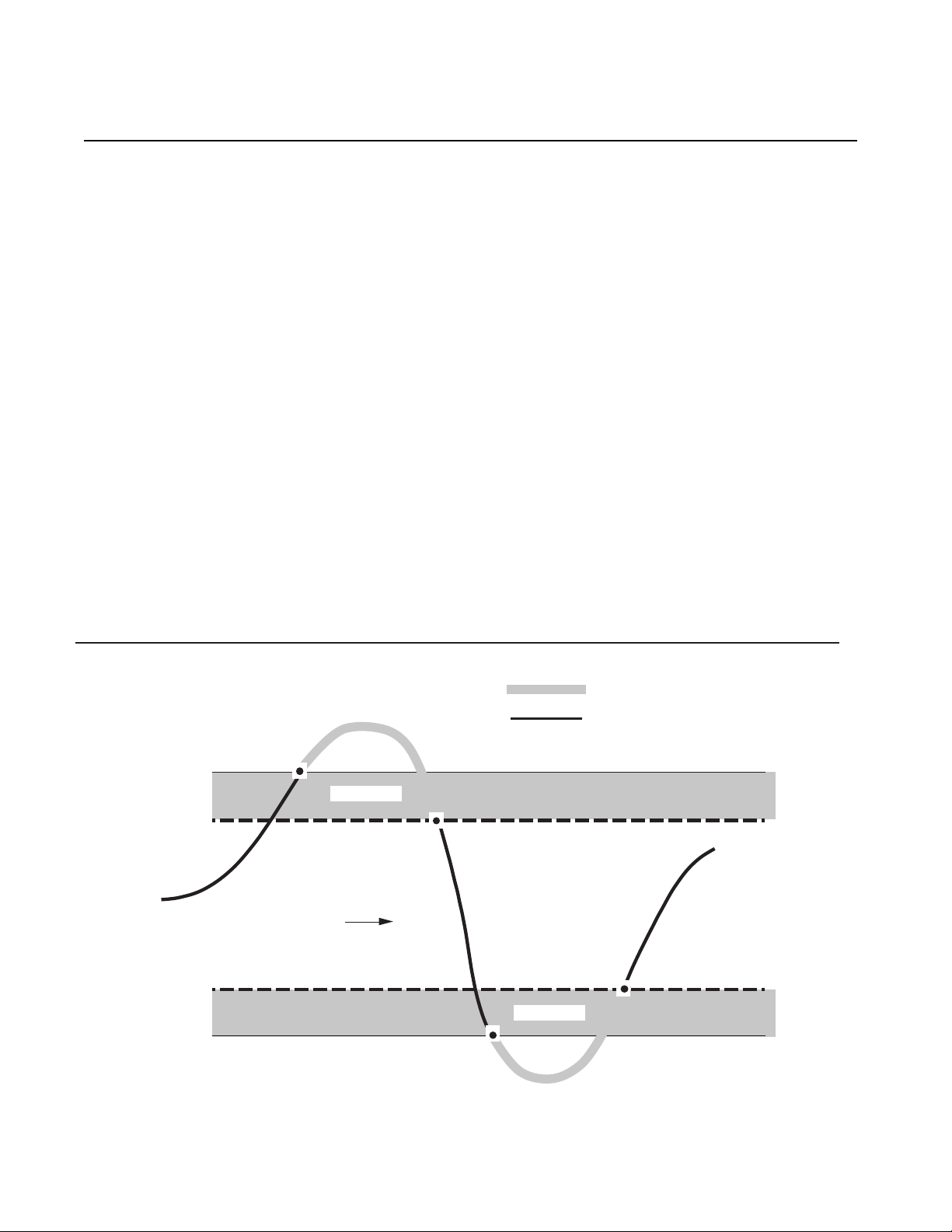
Figure 1 illustrates the way the DDA alarm operates.
For more in depth information, contact the factory for
a copy of Moore Industries’ publication “Alarm Trips:
The Ups and Downs”.
Trip Point is the process input level at which the
user wants an alarm relay to change state, typically
going into an alarm condition, or “tripping”. The DDA
alarm trip point is set by adjusting the TRIP potentiometer.
High Alarms trip when the process input goes
above the trip point. Low Alarms trip when the
process input drops below the trip point. The DDA
alarm output can be set to function as either a high
or low alarm.
Reset Point is the process input level at which the
alarm relay changes state, going from alarm to nonalarm. The reset point is not necessarily the same
as the trip point, because most applications call for
a buffer zone or “deadband” around the trip point to
allow for minute fl uctuations in the process input.
Deadband is the range in which an alarm relay remains in an alarm condition even after the monitored
process variable input has returned to a safe level,
at or below/above the trip point setting. The standard deadband for the DDA is 1% of the input span
unless the unit is equipped with the AD option. AD
units have an adjustable deadband of 1-20% of the
input span.
The relays of a Failsafe Alarm are de-energized
when tripped or power is lost, energized when the
process input is at a non-alarm level. Non-failsafe
Alarm relays are energized when tripped, de-energized when the process input is at a non-alarm
level. The DDA alarm option can be switched from
failsafe to non-failsafe at any time by changing the
jumper settings.
Figure 1. How the DDA Alarm Operates
The Interface Solution Experts
Page 7
Page 5
DDA
DDA Controls
The DDA’s controls consist of: the Display Control
located on the front panel, the internal jumpers, and
the internal and external potentiometer adjustments.
Display Control. The Display Control allows you to
select the currently applied input signal or a trip point
setting for viewing on the LCD.
When the Display Control is rotated to the position
labeled “INPUT”, the LCD displays a percent of
span. For units equipped with the EU Option, the
displayed values depend on the user-selected range
that the unit is configured for.
To view the A or B trip point setting, rotate the Display Control to the position labeled “A” or “B”, respectively. The trip point setting(s) can be varied at
this point by adjusting the corresponding trip point
potentiometer.
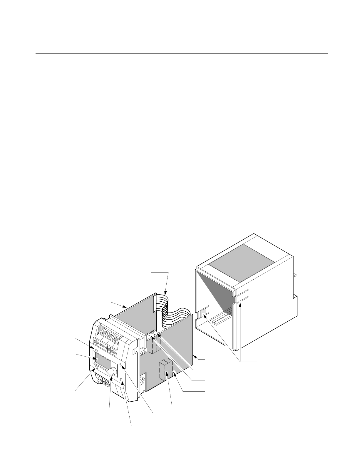
Figure 2. Disassembling the DDA
Single-alarm units have a single trip point setting
designated as “A” on the front panel. Rotating the
Display Control to position A displays the trip point
setting for output A in a percent of span for standard
units (a unique value is displayed for DDAs with the
EU Option). The A trip point potentiometer is used to
adjust the trip point setting to the desired value (see
Figure 2).
Dual-alarm units have two trip point settings: A and
B. Rotating the Display Control to either trip point
displays the corresponding trip point setting on the
LCD. A separate potentiometer is provided for each
trip point. Single-alarm units have only an “A” trip
point potentiometer. Figure 2 shows the location of
the trip point potentiometers for dual and singlealarm units. Single-alarm units do not have “B” trip
point potentiometers.
Units equipped with the Engineering Units (EU) Option display the input and trip point values in userspecified units-of-measure.
TRIP
POINT A
LED
LCD
TRIP
POINT B
LED
DISPLAY
CONTROL
PC3
INNER CONNECTING
RIBBON CABLE
TRIP POIN T B
ADJUSTMEN T
TRIP POIN T A
ADJUSTMEN T
PC4
ZERO ADJUSTMENT
SPAN AD JU STM ENT
TRIP POIN T B
AD OPT ION ADJUSTM ENT
TRIP POIN T A
AD OPT ION ADJUSTM ENT
NOTE: D is ass embly is requir ed to acces s
jum pers and i nternal potenti om eter s.
RELEASE TABS
The Interface Solution Experts
Page 8
Page 6
E
L
J
D
J
DDA
Jumpers. The DDA is field-configured with remov-
able jumpers for the following functions:
• High- or low-alarm configuration
• Failsafe or non-failsafe operation
• Engineering units range (EU Option)
• Decimal point position on the LCD (EU Option)
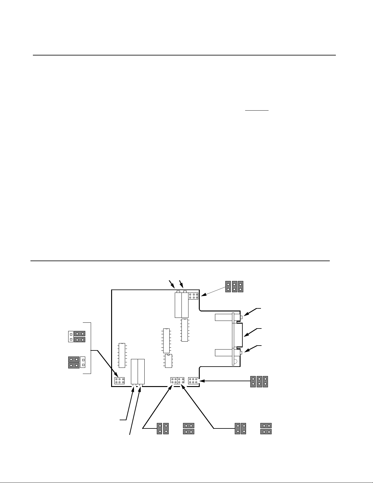
All jumpers are located on PC4 (see Figure 2).
These are accessed by removing the DIN housing.
To remove the housing, pry each of the release tabs
outward with a screwdriver. After the first release
tab is open, pull the unit forward to keep the tab from
reinserting itself. Use the screwdriver to pry out the
second tab, then pull the unit from the housing. The
jumper and potentiometer locations are shown in
Figure 3.
Table 1 (see page 7) lists the jumper settings for
failsafe or non-failsafe modes. Table 2 (see page 7)
lists the jumper settings for high- or low-alarm operation. Table 3 (see page 7) lists the jumper settings for the EU Option and decimal point position.
Match the jumper designations in Figure 3 with the
jumper tables to identify the location of the jumper
pins to be shorted.
Caution:
Use static control procedures when
changing jumper settings in order to avoid
damaging the DDA’s internal components.
Potentiometers. The trip point adjustments are the
external potentiometers located on the front panel.
One trip-point potentiometer is provided for singlealarm units, and two are provided for dual-alarm
units. The trip point potentiometers vary the trip
point settings within the established display range of
the unit. Figure 2 on page 5 shows the location of
trip point potentiometers A and B.
The Zero and Span Potentiometers and the Adjustable Dead Band Potentiometers (with AD Option
only) are adjusted internally. These potentiometers
are located on PC4. The DDA must be disassembled to access them. Figure 3 shows the location of these potentiometers on PC4.
Figure 3. PC4 Component Locations
J405
J407
J404
J406
TRIP POINT B
AD OPTION
ADJUSTMENT
TRIP POINT A
The Interface Solution Experts
R429
R428
J409
J411
R409
R410
J412
J410
EU OPTION
JUMPERS
DECIMAL POI
OPTION ON
J413
TRI
AD
LC
TRI
AD
J417
J418
JUMPERS (
J415
(OR)(OR)
J419
Page 9

Table 1. Failsafe/Non-failsafe Jumper Settings Table 2. High/Low Alarm Jumper Settings
Page 7
DDA
Channel/Mode
A/Failsafe
A/Non-Failsafe
B/Failsafe
B/Non-Failsafe
Table 3. EU Option Display Range Jumper Settings
J406
Installed
Stored
J404
Installed
Stored
Display Ranges
0-.200 to 0-.249
0-.250 to 0-.499
0-.500 to 0-.999
0-1.000 to 0-1.999
J407
Stored
Installed
J405
Stored
Installed
Range Jumpers Decimal Point Jumpers
J401
Stored
Stored
Installed
Stored
J402
Stored
Installed
Stored
Stored
Channel/
Status
A/High
A/Low
B/High
B/Low
J403
Installed
Stored
Stored
Stored
J409
Stored
Installed
J413
Stored
Installed
J417
Stored
Stored
Stored
Stored
J410
Installed
Stored
J414
Installed
Stored
J418
Stored
Stored
Stored
Stored
Jumpers
J411
Stored
Installed
J415
Stored
Installed
J418
Installed
Installed
Installed
Installed
J412
Installed
Stored
J416
Installed
Stored
0-2.00 to 0-2.49
0-2.50 to 0-4.99
0-5.00 to 0-9.99
0-10.00 to 0-19.99
0-20.0 to 0-24.9
0-25.0 to 0-49.0
0-50.0 to 0-99.9
0-100.0 to 0-199.9
0-200 to 0-249
0-250 to 0-499
0-500 to 0-999
0-1000 to 0-1999
Stored
Stored
Installed
Stored
Stored
Stored
Installed
Stored
Stored
Stored
Installed
Stored
Stored
Installed
Stored
Stored
Stored
Installed
Stored
Stored
Stored
Installed
Stored
Stored
Installed
Stored
Stored
Stored
Installed
Stored
Stored
Stored
Installed
Stored
Stored
Stored
Stored
Stored
Stored
Stored
Installed
Installed
Installed
Installed
Stored
Stored
Stored
Stored
Installed
Installed
Installed
Installed
Stored
Stored
Stored
Stored
Stored
Stored
Stored
Stored
Stored
Stored
Stored
Stored
Stored
Stored
Stored
Stored
Stored
Stored
Stored
Stored
The Interface Solution Experts
Page 10

Page 8
DDA
Calibration Setup
Table 4 lists the equipment required to calibrate the
DDA.
Figures 4 and 5 (see pages 8 and 9, respectively)
show the calibration hookup required for single- and
dual-alarm units with relay outputs. Figures 6 and 7
(see pages 9 and 10, respectively) show the hookup
required for single- and dual-alarm units with the
TSO Option. Figure 8 on page 10 shows the hookup
required to calibrate a unit with the (DA) Option. The
tables adjacent to each drawing contain the terminal
designations. Use these in conjunction with the calibration drawings to connect the DDA.
Table 4. Calibration Equipment
Equipment
Adjustable
Current or
Voltage Source
Description
Appropriate for the input type and
capable of producing the input range
necessary for the unit (two sources
required for -DA option)
Ohmmeter
DC Voltmeter
Accurate to within 1%
Voltmeter: accuracy to 0.05% or better
(optional)
Milliammeter
Accuracy of 0.05% or better
(optional)
Power Supply
Screwdriver
24Vdc @ 1A
Slotted-head; head width no greater
than 2.54 mm (0.1 in)
Figure 4. Calibrating the Single-alarm DDA
OHMMETER
24 VDC
+
POWER SOURCE
See n ot es
—
11 12 13 14 15 16 1718
DDA
A
D C CURRE NT ALARM
%
12
—IN
+IN
—
MILLIAMET ER
See n ot es
+
ADJUSTABLE
CURRENT / VOL TAGE
INPUT S OURCE
—
VOLTMETER
+
+
—
See n ot es
NOTES:
1) Either a milliameter or a
dc voltmeter is required
TRIP
A
910
OPT IONAL M A NUA L
RESET PUSHBUTT ON
for calibraion, but not both.
2) On actual units, the
terminal numbers appear on
the side of the unit.
3) On most ohmmeters, only
NO or NC can be tested at a
time. Connect the one that is
needed.
4) See adjacent table for
terminal designations.
5) The manual reset
pushbuttons are not supplied
with the DDA, however, they
are required for MR equipped
units.
( See no t es)
Terminal
Numbers
10
11
12
13
14
15
16
17
18
Terminal
Numbers
1
+IN
-IN
2
Manual Reset (Optional)
9
Manual Reset (Optional)
+ Power
- Power
Normally Open, Contact 1
Common, Contact 1
Normally Closed, Contact 1
Normally Open, Contact 2
Common, Contact 2
Normally Closed, Contact 2
The Interface Solution Experts
Page 11

Page 9
DDA
Figure 5. Calibrating the Dual-alarm DDA
A
OHMMETER
DDA
D C CURRENT ALARM
24 VDC
POWER
SOURCE
See notes
—
+
11 12 13 14 15 16 17 18
%
B
12 78910
+IN —IN
See notes
ADJUSTABLE
INPUT SOURCE
VOLTMETER
OPTIONAL
MANUAL
RESET
PUSHBUTTON
(See notes)
MILLIAMETER
—
+
CURRENT/VOLTAGE
See notes
TRIP
A
INPUT
B
TRIP
OPTIONAL
MANUAL
RESET
PUSHBUTTON
(See notes)
NNNNOOOOTTTTEEEESSSS::::
1) Either a millammeter or a
dc voltmeter is required
for calibration, but not both.
2) On actual units, the
terminal numbers appear on
the side of the unit.
3) On most ohmmeters, only
NO or NC can be tested at a
time. Connect the one that is
needed.
4) See the adjacent table for
terminal desegnations.
5) The manual reset
pushbuttons are not supplied
with the DDA, however they
are required for MR equipped
units.
Terminal
Numbers
10
11
12
13
14
15
16
17
18
Terminal Labels
+IN
1
-IN
2
Channel B, Manual Reset, (Optional)
7
Channel B, Manual Reset, (Optional)
8
Channel A, Manual Reset, (Optional)
9
Channel A, Manual Reset, (Optional)
+ Power
- Power
Channel A, Normally Open
Channel A, Common
Channel A, Normally Closed
Channel B, Normally Open
Channel B, Common
Channel B, Normally Closed
Figure 6. Calibrating Single-alarm DDAs with the Transistor Switch Output Option
24 VDC
—
POWER
+
SOURCE
11 12 13 14 15 16 17 18
DDA
A
D C CURRENT ALARM
TRIP
NNNNOOOOTTTTEEEESSSS::::
1) On actual units, the terminal
numbers apear on the side
of the unit.
2) See adjacent table for
terminal designations.
A
%
INPUT
12
3
ADJUSTABLE
CURRENT/VOLTAGE
INPUT SOURCE
ADJUSTABLE
CURRENT/VOLTAGE
INPUT SOURCE
Terminal
Numbers
10
11
12
13
14
Terminal Labels
+IN
1
-IN
2
Manual Reset, (Optional)
9
Manual Reset, (Optional)
+ Power
- Power
+ Transistor Switch Output
- Transistor Switch Output
The Interface Solution Experts
Page 12

Page 10
DDA
Figure 7. Calibrating the Dual-alarm DDA with the Transistor Switch Output Option
MILLIAMETER
VOLTMETER
24 VDC
POWER
SOURCE
See notes
–
+
–
+
11 12 13 14 15 16 17 18
12 78910
–
See notes
+
ADJUSTABLE
CURRENT/VOLTAGE
INPUT SOURCE
A
B
+–
POWER
SUPPLY
–
(60 V, MAX)
+
DDA
D C CURRENT ALARM
–
VOLTMETER
+
OPTIONAL
MANUAL
RESET
PUSHBUTTON
(See notes)
+
–
%
–
VOLTMETER
+
TRIP
A
INPUT
B
TRIP
OPTIONAL
MANUAL
RESET
PUSHBUTTON
(See notes)
NNNNOOOOTTTTEEEESSSS::::
1) Either a millammeter or a
dc voltmeter is required
for calibration, but not both.
2) On actual units, the
terminal numbers appear on
the side of the unit.
3) See the adjacent table for
terminal designations.
4) The manual reset
pushbuttons are not supplied
with the DDA, however they
are required for MR equipped
units.
Terminal
Numbers
10
11
12
13
14
17
18
Terminal Labels
+IN
1
-IN
2
Channel B, Manual Reset, (Optional)
7
Channel B, Manual Reset, (Optional)
8
Channel A, Manual Reset, (Optional)
9
Channel A, Manual Reset, (Optional)
+ Power
- Power
+ Channel A, Transistor Switch Output
- Channel A, Transistor Switch Output
+ Channel B, Transistor Switch Output
- Channel B, Transistor Switch Output
Figure 8. Calibrating the DDA with the Deviation Alarm Option
24 VDC
POWER SOURCE
+
–
11 12
TRIP
DDA
A
D C CURRENT ALARM
123
SOURCE B SOURCE A
++––
ADJUSTABLE
CURRENT/VOLTAGE
INPUT SOURCE
4
ADJUSTABLE
CURRENT/VOLTAGE
INPUT SOURCE
A
%
Notes:
1) On actual units, the terminal
numbers appear on the side
INPUT
of the unit.
2) See the adjacent table for
terminal designations.
Terminal
Numbers
11
12
Terminal
Labels
1
+IN
2
+ Reference
3
Common
+ Power
- Power
The Interface Solution Experts
Page 13

Page 11
DDA
Calibration Procedures
Note:
Before calibration, partially disassemble the
DDA (see Figures 2 and 3 on pages 5 and
6, respectively).
DA equipped DDAs are calibrated differently than
standard units (see page 12).
To calibrate the DDA:
1. Set jumpers J409 through J416 on PC4
for a high- or low-alarm (see Table 2 on
page 7 and Figure 3 on page 6).
2. Connect the DDA in the correct
calibration hookup (see Figures 4-7 on
pages 8-10).
3. Turn the Display Control to INPUT.
4. Apply power to the unit.
5. Set the input signal to 0 percent of the
input range. The DDA display should
read 00.0. If not, adjust the Zero
Potentiometer (R409) until 00.0 is
displayed.
Note:
On EU-equipped DDAs, the display may be
set to any user-selected value less than
1999 by adjusting the Zero potentiometer
(R409) (refer to Table 3 on page 7).
6. Set the input signal source to 100
percent of the input range. The DDA’s
display should read 100.0. If not,
adjust the Span Potentiometer (R410)
until 100.0 is displayed (see Figure 3
on page 6).
7. Verify the 0 and 100 percent readings
by repeating steps 5-6. Then apply 25-,
50-, and 75 percent inputs to verify that
the input is linear. If the input is not
linear, repeat steps 5-6.
8. Turn the Display Control to TRIP A.
9. Adjust the TRIP A Potentiometer for a
display reading of the desired trip point
value, as a percent of span.
10. For dual alarm units, turn the Display
Control to TRIP B and repeat step 9
using the TRIP B Potentiometer.
11. Turn the Display Control to INPUT and
set the input source to a value outside
the alarm range.
12. Observe the DDA output (A or B) with
an output monitoring device and
increase or decrease the input towards
the trip point setting.
13. Verify the output trips at selected trip
point settings by observing the reaction
of the ohmmeter.
14. Increase and decrease the input
through the trip point setting and verify
that the output changes state.
Note:
Units with the MR Option require manual
resetting after the input has exceeded the
trip point. Reset the trip point manually
after returning to the non-alarm range.
Units with the AR Option will trip after the
input has remained beyond the trip point
setting for the built-in time delay.
Units with the AD Option will reset at a user-
selected setting (see page 12).
Note:
For units with the EU option, the display
may be set to any user-selected value less
than 1999 by adjusting the Span
potentiometer (R410) (refer to Table 3 on
page 7).
15. Disconnect calibration equipment and
re-assemble the DDA.
The Interface Solution Experts
Page 14

Page 12
DDA
Setting Deadband for AD
Equipped Units
The Adjustable Dead Band (AD) Option provides an
adjustable 1-20 percent deadband. After calibrating
the DDA, deadband is set for AD equipped units by
performing the following steps:
1. Turn the Deadband A Potentiometer
(R429) fully counterclockwise (see
Figure 3 on page 6).
2. Apply power and an input signal equal
to the desired trip point setting.
3. Slowly turn the TRIP A Potentiometer
on the front panel until the unit goes
into an alarm state. Then turn the
Deadband A Potentiometer fully
clockwise.
4. Apply an input signal equal to the
desired reset point. Slowly turn the
Deadband A potentiometer
counterclockwise until the alarm
resets (output returns to a non-alarm
state).
3. Set input source A to 0 percent of input
span and source B to 100 percent of
input span.
4. Adjust the Span Potentiometer for a
display reading of 100.0.
5. Set the input sources to the same
values within the input span range.
Verify that the display reading is 50.0.
6. Select another value within the input
span and set both sources to the new
value. Verify that the display reading is
50.0.
7. Change the input settings to various
values and note that the display
changes in proportion to the difference
in the two inputs by adding or
subtracting the difference from 50.0
percent.
8. Disconnect the calibration equipment
and reassemble the DDA.
5. Increase and decrease input through
trip point and deadband to verify
reaction of output.
6. For dual alarm units, repeat steps 1
through 5 for trip point B using the
TRIP B and Deadband B
Potentiometers
Calibrating a Unit with the DA Option
To calibrate units equipped with the DA Option, the
DDA must be set up as shown in Figure 8 on page
10. Two input sources are required for this calibration procedure.
To calibrate DA equipped units:
1. Set input source A to 100 percent of
input span and source B to 0 percent
of input span.
2. Adjust the Zero Potentiometer to a
display reading of 00.0.
The Interface Solution Experts
Page 15

Page 13
INSERT SLOTTED SCREWDRIVER
HERE TO REMOVE/MOUNT UNIT
FROM/ONTO RAIL
80 mm
(3.15 in)
60 mm
(2.36 in)
A
B
DDA
TRIP
TRIP
A
B
INPUT
D C CURRENT ALARM
125.73 mm
(4.95 in)
146.05 mm
(5.75 in)
%
OPTIONAL
G RAIL
ADAPTOR
TOP-HAT RAIL
C
L
39.84 mm
(1.57 in)
DDA
Installation
Installing the DDA consists of physically mounting
the unit and making the appropriate electrical connections.
Mounting the DDA
The standard DDA is designed to mount directly on
a DIN-style, top-hat rail. With the optional DIN-style
G-rail adaptor, the DDA can also be mounted on a
DIN-style G-rail.
Figure 9. Dimensions of the DDA
To mount the DDA on hat rail, place the upper extrusion on the back of the unit over the top edge of the
hat rail. Insert the screwdriver over the bottom edge
of the sliding retainer clip. Pull the clip down until the
unit snaps onto the hat rail.
Figure 9 shows the outline dimensions of the DDA.
Note:
Attention should be given to spacing
beneath the unit to ensure adequate room
for inserting the screwdriver required to
mount and remove the unit (see Figure 9).
The Interface Solution Experts
Page 16

Page 14
DDA
Making the Electrical Connections
All electrical connections are made to removable
blocks across the top and bottom of the front panel.
Terminals are labeled on the top and bottom surfaces of the unit with the corresponding connection
for each terminal.
Figures 10-20 on pages 14-21 illustrate typical installation hookups for the DDA. The tables adjacent
to each drawing contain the terminal designations.
Use these in conjunction with the drawings to install
the DDA.
Recommended Ground
Wiring Practices
Moore Industries recommends the following ground
wiring practices:
• Any Moore Industries product in a metal case
or housing should be grounded.
• All input signals to, and output signals from,
Moore Industries’ products should be wired
using a shielded, twisted pair technique.
Shields are to be connected to an earth or
safety ground at the unit itself.
• The maximum length of unshielded input
and/or output signal wiring should be 2
inches.
• Static control procedures must be used when
the cover or housing is removed from a unit.
Operation
Once properly calibrated, connected, and powered,
the DDA will operate reliably for an extended period
of time. Unit maintenance is a simple check of terminal connections every six months. A specific
maintenance schedule for the DDA should be developed based on the environment in which it is operated.
If a DDA begins to malfunction or to function below
rated specifications, complete the following checklist
before calling the factory for assistance:
• Verify that all electrical connections are clean
and tight.
• Verify that the power source for the unit is
supplying power at levels rated safe and
appropriate according to product
specifications.
• Verify that the process signal has not changed
dramatically in an unexpected manner.
• Check the calibration of the instruments used
in calibrating the DDA.
• Verify that other devices in the process loop
are not the cause of the problem.
• Verify that input to output isolation still exists.
• If the unit is equipped with the MR option,
verify that the shorting pushbutton is working
properly.
CE Conformity
Installation of any Moore Industries products that
carry the CE certification (Commission Electrotechnique)
to meet the requirements set forth in applicable EMC
(Electromagnetic Compatibility) directives
(EN55011, EN 50082-1, EN50082-2, etc.)
Consult the factory for the most current information
on products that have been CE certified.
must
adhere to the guidelines above in order
The Interface Solution Experts
If the difficulties continue, remove the unit from service and recalibrate. The removable terminal blocks
on the front panel make it easy to replace the DDA
without having to rewire.
Page 17

Figure 10. Installing the Single-alarm DDA
Page 15
DDA
24 VDC
POWER
SOURCE
CURRENT
–
+
DRIVEN
DEVICE
11 12 13 14 15 16 17 18
A
CURRENT
DRIVEN
DEVICE
DDA
D C CURRENT ALARM
TRIP
A
%
INPUT
12
+–
CURRENT OR
VOLTAGE OUTPUT
DEVICE
910
OPTIONAL
MANUAL
RESET
PUSHBUTTON
(See notes)
Figure 11. Installing the Dual-alarm DDA
NNNNOOOOTTTTEEEE::::
1) On actual units, the
terminal numbers appear on
the side of the unit.
2) See the adjacent table
for terminal designations.
3) Manual Reset pushbutton
is not supplied but is
required for —MR equipped
units.
4) The manual reset
pushbutton is not supplied
with the DDA, however it is
required for MR equipped
units.
Terminal
Numbers
10
11
12
13
14
15
16
17
18
Terminal Labels
+IN
1
-IN
2
Manual Reset, (Optional)
9
Manual Reset, (Optional)
+ Power
- Power
Normally Open, Contact 1
Common, Contact 1
Normally Closed, Contact 1
Normally Open, Contact 2
Common, Contact 2
Normally Closed, Contact 2
24 VDC
–
POWER
+
SOURCE
11 12 13 14 15 16 17 18
A
BB
12
CURRENT OR
VOLTAGE OUTPUT
+–
DEVICE
CURRENT
DRIVEN
DEVICE
DDA
D C CURRENT ALARM
OPTIONAL
MANUAL
RESET
PUSHBUTTON
(see note)
CURRENT
DRIVEN
DEVICE
%
78
TRIP
A
INPUT
TRIP
910
OPTIONAL
MANUAL
RESET
PUSHBUTTON
(see note)
NNNNOOOOTTTTEEEE::::
1) On actual units, the
terminal numbers appear on
the side of the unit.
2) See the adjacent table
for terminal designations.
3) The manual reset
pushbuttons are not supplied
with the DDA, however they
are required for MR equipped
units.
Terminal
Numbers
10
11
12
13
14
15
16
17
18
Terminal Labels
+IN
1
-IN
2
Channel B, Manual Reset, (Optional)
7
Channel B, Manual Reset, (Optional)
8
Channel A, Manual Reset, (Optional)
9
Channel A, Manual Reset, (Optional)
+ Power
- Power
Channel A, Normally Open
Channel A, Common
Channel A, Normally Closed
Channel B, Normally Open
Channel B, Common
Channel B, Normally Closed
The Interface Solution Experts
Page 18

Page 16
DDA
Figure 12. Installing the Single-alarm DDA with the Transistor Switch Output Option
POWER SUPPLY
60V MAXIMUM
24 VDC
POWER
SOURCE
+–
–
+
11 12 13 14 15 16 17 18
A
DDA
D C CURRENT ALARM
12
–
VOLTMETER
+
TRIP
A
%
INPUT
TRIP
910
NNNNOOOOTTTTEEEE::::
1) On actual units, the
terminal numbers appear on
the side of the unit.
2) See the adjacent table for
terminal designations.
3) The manual reset
pushbutton is not supplied
with the DDA, however it is
required for MR equipped units.
Terminal
Numbers
Terminal Labels
+IN
1
-IN
2
Manual Reset, (Optional)
9
Manual Reset, (Optional)
10
+ Power
11
- Power
12
+ Transistor Switch Output
13
- Transistor Switch Output
14
+–
CURRENT OR
VOLTAGE OUTPUT
DEVICE
OPTIONAL
MANUAL
RESET
PUSHBUTTON
(See notes)
Figure 13. Installing the Dual-alarm DDA with the Transistor Switch Output Option
POWER SUPPLY
24 VDC
POWER
SOURCE
60V MAXIMUM
–
+
11 12 13 14 17 18
A
BB
12
–+
–
VOLTMETER
+
DDA
D C CURRENT ALARM
%
78
TRIP
A
INPUT
TRIP
910
NNNNOOOOTTTTEEEE::::
1) On actual units, the
terminal numbers appear on
the side of the unit.
2) See adjacent table for
terminal designations.
3) The manual reset
pushbuttons are not supplied
with the DDA, however they
are required for MR equipped
units.
Terminal
Numbers
Terminal Labels
+IN
1
-IN
2
B Manual Reset, (Optional)
7
B Manual Reset, (Optional)
8
A Manual Reset, (Optional)
9
A Manual Reset, (Optional)
10
+ Power
11
- Power
12
+ A Transistor Switch Output
13
CURRENT OR
VOLTAGE OUTPUT
+–
DEVICE
OPTIONAL
MANUAL
RESET
PUSHBUTTON
(See notes)
The Interface Solution Experts
OPTIONAL
MANUAL
RESET
PUSHBUTTON
(See notes)
- A Transistor Switch Output
14
+ B Transistor Switch Output
17
- B Transistor Switch Output
18
Page 19

Figure 14. Installing the Dual-alarm DDA with the Double-Pole/Single-Throw, Normally Open Relays Option
Page 17
DDA
24 VDC
–
POWER
+
SO URCE
11 12 13 14 15 16 17 18
A
B
12
+–
CURRENT O R
VOLTAGE O UTPUT
DEVICE
CURRENT
DRIV EN
DEVICE
DDA
D C CURRE NT ALARM
OPTIONAL
MANUA L
RESET
PUSHBUTTO N
(See notes )
CURRENT
DRIV EN
DEVICE
%
78
19 20
TRIP
A
INPUT
B
TRIP
910
OPTIONAL
MANUA L
RESET
PUSHBUTTO N
(See notes )
NOTE:
1) On act ual unit s, t he
terminal numbers appear on
the side of the unit.
2) See the adjacent t able for
terminal designations.
3) The manu al reset
pushbuttons are not supplied
wit h t he DDA, however they
are required for MR equipped
unit s.
Terminal
Numbers
10
11
12
13
14
15
16
17
Terminal Labels
+IN
1
-IN
2
B Manual Reset, (Optional)
7
B Manual Reset, (Optional)
8
A Manual Reset, (Optional)
9
A Manual Reset, (Optional)
+ Power
- Power
Channel A, Normally Open, Contact 1
Channel A, Common, Contact 1
Channel A, Normally Open, Contact 2
Channel A, Common, Contact 2
Channel B, Normally Open, Contact 1
Channel B, Common, Contact 1
18
Channel B, Normally Open, Contact 2
19
Channel B, Common, Contact 2
20
The Interface Solution Experts
Page 20

Page 18
DDA
Figure 15. Installing the Dual-alarm DDA with the Double-Pole/Single-Throw, Normally Closed Relays Option
24 VDC
–
POWER
+
SO URCE
11 12 13 14 15 16 17 18
A
B
12
+–
CURRENT O R
VOLTAGE O UTPUT
DEVICE
CURRENT
DRIV EN
DEVICE
DDA
D C CURRE NT ALARM
OPTIONAL
MANUA L
RESET
PUSHBUTTO N
(See notes )
CURRENT
DRIV EN
DEVICE
%
78
19 20
TRIP
A
INPUT
B
TRIP
910
OPTIONAL
MANUA L
RESET
PUSHBUTTO N
(See notes )
NOTE:
1) On act ual unit s, t he
terminal numbers appear on
the side of the unit.
2) See the adjacent t able for
terminal designations.
3) The manu al reset
pushbuttons are not supplied
wit h t he DDA, however they
are required for MR equipped
unit s.
Terminal
Numbers
10
11
12
13
14
15
16
17
Terminal Labels
+IN
1
-IN
2
Channel B Manual Reset, (Optional)
7
Channel B Manual Reset, (Optional)
8
Channel A Manual Reset, (Optional)
9
Channel A Manual Reset, (Optional)
+ Power
- Power
Channel A, Normally Closed, Contact 1
Channel A, Common, Contact 1
Channel A, Normally Closed, Contact 2
Channel A, Common, Contact 2
Channel B, Normally Closed, Contact 1
Channel B, Common, Contact 1
18
Channel B, Normally Closed, Contact 2
19
Channel B, Common, Contact 2
20
The Interface Solution Experts
Page 21

Page 19
DDA
Figure 16. Installing the Dual-alarm DDA with the Double-Pole/Single-Throw, Normally Open/Normally Closed Relays Option
24 VDC
–
POWER
+
SOURCE
11 12 13 14 15 16 17 18
A
BB
12
CURRENT OR
VOLTAGE OUTPUT
+–
DEVICE
CURRENT
DRIVEN
DEVICE
DDA
D C CURRENT ALARM
OPTIONAL
MANUAL
RESET
PUSHBUTTON
(See notes)
CURRENT
DRIVEN
DEVICE
19 20
%
78
910
PUSHBUTTON
TRIP
A
INPUT
TRIP
OPTIONAL
MANUAL
RESET
(See notes)
NNNNOOOOTTTTEEEE::::
1) On actual units, the
terminal numbers appear on
the side of the unit.
2) See the adjacent table for
terminal designations.
3) The manual reset
pushbuttons are not supplied
with the DDA, however they
are required for MR equipped
units.
Terminal
Numbers
10
11
12
13
14
15
16
17
18
Terminal Labels
+IN
1
-IN
2
B Manual Reset, (Optional)
7
B Manual Reset, (Optional)
8
A Manual Reset, (Optional)
9
A Manual Reset, (Optional)
+ Power
- Power
Channel A, Normally Open, Contact 1
Channel A, Common, Contact 1
Channel A, Normally Closed, Contact 2
Channel A, Common, Contact 2
Channel B, Normally Open, Contact 1
Channel B, Common, Contact 1
Figure 17. Installing the Single-alarm DDA with the Deviation Alarm Option
24 VDC
–
POWER
+
SOURCE
CURRENT OR
VOLTAGE OUTPUT
DEVICE
CURRENT
DRIVEN
DEVICE
11 12 13 14 15 16 17 18
A
3
12
+–
+–
CURRENT OR
VOLTAGE OUTPUT
CURRENT
DDA
D C CURRENT ALARM
4
DEVICE
DRIVEN
DEVICE
%
OPTIONAL
MANUAL
RESET
PUSHBUTTON
(See notes)
TRIP
A
INPUT
TRIP
910
NNNNOOOOTTTTEEEE::::
1) On actual units, the
terminal numbers appear on
the side of the unit.
2) See the adjacent table for
terminal designations.
3) The manual reset
pushbutton is not supplied
with the DDA, however it is
required for MR equipped
units.
19
20
Terminal
Numbers
10
11
12
13
14
15
16
17
18
Channel B, Normally Closed, Contact 2
Channel B, Common, Contact 2
Terminal Labels
1
+IN
2
+ Reference
3
Common
9
Manual Reset, (Optional)
Manual Reset, (Optional)
+ Power
- Power
Normally Open, Contact 1
Common, Contact 1
Normally Closed, Contact 1
Normally Open, Contact 2
Common, Contact 2
Normally Closed, Contact 2
The Interface Solution Experts
Page 22

Page 20
DDA
Figure 18. Installing the Dual-alarm DDA with the Deviation Alarm Option
24 VDC
POWER
SOURCE
CURRENT
VOLTAGE
OUTPUT
DEVICE
CURRENT
–
+
11 12 13 14 15 16 17 18
A
BB
12
+–
+–
CURRENT
OR
OR
VOLTAGE
OUTPUT
DEVICE
CURRENT
DRIVEN
DEVICE
DDA
D C CURRENT ALARM
4
OPTIONAL
MANUAL
RESET
PUSHBUTTON
(See notes)
DRIVEN
DEVICE
%
783
TRIP
A
INPUT
TRIP
910
OPTIONAL
MANUAL
RESET
PUSHBUTTON
(See notes)
NNNNOOOOTTTTEEEE::::
1) On actual units, the
terminal numbers appear on
the side of the unit.
2) See the adjacent table for
terminal designations.
3) The manual reset
pushbuttons are not supplied
with the DDA, however they
are required for MR equipped
units.
Terminal
Numbers
10
11
12
13
14
15
16
17
Terminal Labels
+IN
1
+ Reference
2
Common
3
Channel B Manual Reset, (Optional)
7
Channel B Manual Reset, (Optional)
8
Channel A Manual Reset, (Optional)
9
Channel A Manual Reset, (Optional)
+ Power
- Power
Channel A, Normally Open
Channel A, Common
Channel A, Normally Closed
Channel B, Normally Open
Channel B, Common
Figure 19. Installing the Single-alarm DDA with the Transmitter Excitation Option
24 VDC
POWER
SOURCE
CURRENT
–
DRIVEN
DEVICE
+
11 12 13 14 15 16 17 18
A
34
12
LOOP-POWERED
DEVICE
CURRENT
DRIVEN
DEVICE
DDA
D C CURRENT ALARM
+–
TRIP
A
%
INPUT
TRIP
910
OPTIONAL
MANUAL
RESET
PUSHBUTTON
(See notes)
NNNNOOOOTTTTEEEE::::
1) On actual units, the
terminal numbers appear on
the side of the unit.
2) See the adjacent table for
terminal designations.
3) The manual reset
pushbutton is not supplied
with the DDA, however it is
required for MR equipped
units.
18
Channel B, Normally Closed
Terminal
Terminal Labels
Numbers
1
+IN
2
- IN
4
+ Transmitter Excitation
9
Manual Reset, (Optional)
10
Manual Reset, (Optional)
11
+ Power
12
- Power
13
Normally Open, Contact 1
14
Common, Contact 1
15
Normally Closed, Contact 1
16
Normally Open, Contact 2
17
Common, Contact 2
18
Normally Closed, Contact 2
The Interface Solution Experts
Page 23

Figure 20. Installing the Dual-alarm DDA with the Transmitter Excitation Option
Page 21
DDA
24 VDC
POWER
SOURCE
LOOP-POWERED
CURRENT
DRIVEN
–
DEVICE
+
11 12 13 14 15 16 17 18
A
BB
12
–
4-20MA
DEVICE
CURRENT
DRIVEN
DEVICE
DDA
D C CURRENT ALARM
+
OPTIONAL
MANUAL
RESET
PUSHBUTTON
(See notes)
%
7834
TRIP
A
INPUT
TRIP
910
OPTIONAL
MANUAL
RESET
PUSHBUTTON
(See notes)
NNNNOOOOTTTTEEEE::::
1) On actual units, the
terminal numbers appear on
the side of the unit.
2) See the adjacent table for
terminal designations.
3) The manual reset
pushbuttons are not supplied
with the DDA, however they
are required for MR equipped
units.
Terminal
Numbers
10
11
12
13
14
15
16
17
Terminal Labels
1
+IN
2
-IN
4
+ Transmitter Excitation
7
B Manual Reset, (Optional)
8
B Manual Reset, (Optional)
9
A Manual Reset, (Optional)
A Manual Reset, (Optional)
+ Power
- Power
Channel A, Normally Open
Channel A, Common
Channel A, Normally Closed
Channel B, Normally Open
Channel B, Common
Customer Support
Moore Industries is recognized as the industry
leader in delivering top quality to its customers in
products and services. We perform a battery of
stringent quality assurance checks on every unit we
ship. If any Moore Industries product fails to perform
up to rated specifications, call us for help. Our
highly skilled staff of trained technicians and engineers pride themselves on their ability to provide
timely, accurate, and practical answers to your process instrumentation questions. Factory phone
numbers are on the back cover.
18
Channel B, Normally Closed
If problems involve a particular DDA, there are several pieces of information you can gather
before
you
call the factory that will help our staff get you answers more efficiently. When you call, please have:
• The model number of the unit in question.
• The serial number of the unit in question.
• The job number (if available).
• The purchase order under which the unit was
shipped (if available).
The Interface Solution Experts
Page 24

RETURN PROCEDURES
To return equipment to Moore Industries for repair, follow these four steps:
1. Call Moore Industries and request a Returned Material Authorization (RMA) number.
Warranty Repair –
If you are unsure if your unit is still under warranty, we can use the unit’s serial number
to verify the warranty status for you over the phone. Be sure to include the RMA
number on all documentation.
Non-Warranty Repair –
If your unit is out of warranty, be prepared to give us a Purchase Order number when
you call. In most cases, we will be able to quote you the repair costs at that time.
The repair price you are quoted will be a “Not To Exceed” price, which means that the
actual repair costs may be less than the quote. Be sure to include the RMA number on
all documentation.
2. Provide us with the following documentation:
a) A note listing the symptoms that indicate the unit needs repair
b) Complete shipping information for return of the equipment after repair
c) The name and phone number of the person to contact if questions arise at the factory
3. Use sufficient packing material and carefully pack the equipment in a sturdy shipping
container.
4. Ship the equipment to the Moore Industries location nearest you.
The returned equipment will be inspected and tested at the factory. A Moore Industries
representative will contact the person designated on your documentation if more information is
needed. The repaired equipment, or its replacement, will be returned to you in accordance with
the shipping instructions furnished in your documentation.
WARRANTY DISCLAIMER
THE COMPANY MAKES NO EXPRESS, IMPLIED OR STATUTORY WARRANTIES (INCLUDING ANY WARRANTY OF MERCHANTABILITY OR OF FITNESS
FOR A PARTICULAR PURPOSE) WITH RESPECT TO ANY GOODS OR SERVICES SOLD BY THE COMPANY. THE COMPANY DISCLAIMS ALL WARRANTIES ARISING FROM ANY COURSE OF DEALING OR TRADE USAGE, AND
ANY BUYER OF GOODS OR SERVICES FROM THE COMPANY ACKNOWLEDGES THAT THERE ARE NO WARRANTIES IMPLIED BY CUSTOM OR
USAGE IN THE TRADE OF THE BUYER AND OF THE COMPANY, AND THAT
ANY PRIOR DEALINGS OF THE BUYER WITH THE COMPANY DO NOT IMPLY THAT THE COMPANY WARRANTS THE GOODS OR SERVICES IN ANY
WAY.
ANY BUYER OF GOODS OR SERVICES FROM THE COMPANY AGREES
WITH THE COMPANY THAT THE SOLE AND EXCLUSIVE REMEDIES FOR
BREACH OF ANY WARRANTY CONCERNING THE GOODS OR SERVICES
SHALL BE FOR THE COMPANY, AT ITS OPTION, TO REPAIR OR REPLACE
THE GOODS OR SERVICES OR REFUND THE PURCHASE PRICE. THE
COMPANY SHALL IN NO EVENT BE LIABLE FOR ANY CONSEQUENTIAL OR
INCIDENTAL DAMAGES EVEN IF THE COMPANY FAILS IN ANY ATTEMPT
TO REMEDY DEFECTS IN THE GOODS OR SERVICES , BUT IN SUCH CASE
THE BUYER SHALL BE ENTITLED TO NO MORE THAN A REFUND OF ALL
MONIES PAID TO THE COMPANY BY THE BUYER FOR PURCHASE OF THE
GOODS OR SERVICES.
ANY CAUSE OF ACTION FOR BREACH OF ANY WARRANTY BY THE
COMPANY SHALL BE BARRED UNLESS THE COMPANY RECEIVES
FROM THE BUYER A WRITTEN NOTICE OF THE ALLEGED DEFECT OR
BREACH WITHIN TEN DAYS FROM THE EARLIEST DATE ON WHICH THE
BUYER COULD REASONABLY HAVE DISCOVERED THE ALLEGED DEFECT OR BREACH, AND NO ACTION FOR THE BREACH OF ANY WARRANTY SHALL BE COMMENCED BY THE BUYER ANY LATER THAN
TWELVE MONTHS FROM THE EARLIEST DATE ON WHICH THE BUYER
COULD REASONABLY HAVE DISCOVERED THE ALLEGED DEFECT OR
BREACH.
RETURN POLICY
For a period of thirty-six (36) months from the date of shipment, and under
normal conditions of use and service, Moore Industries ("The Company") will
at its option replace, repair or refund the purchase price for any of its manufactured products found, upon return to the Company (transportation charges
prepaid and otherwise in accordance with the return procedures established
by The Company), to be defective in material or workmanship. This policy
extends to the original Buyer only and not to Buyer's customers or the users
of Buyer's products, unless Buyer is an engineering contractor in which case
the policy shall extend to Buyer's immediate customer only. This policy shall
not apply if the product has been subject to alteration, misuse, accident, neglect or improper application, installation, or operation. THE COMPANY
SHALL IN NO EVENT BE LIABLE FOR ANY INCIDENTAL OR CONSEQUENTIAL DAMAGES.
Tel: (818) 894-7111 • FAX: (818) 891-2816
Tel: (02) 8536-7200 • FAX: (02) 9525-7296
© 2016 Moore Industries-International, Inc.
United States • info@miinet.com
Australia • sales@mooreind.com.au
Belgium • info@mooreind.be
Tel: 03/448.10.18 • FAX: 03/440.17.97
Tel: 86-21-62491499 • FAX: 86-21-62490635
The Netherlands • sales@mooreind.nl
Tel: (0)344-617971 • FAX: (0)344-615920
Specifications and Information subject to change without notice.
China • sales@mooreind.sh.cn
United Kingdom • sales@mooreind.com
Tel: 01293 514488 • FAX: 01293 536852
 Loading...