

Page 1

Demand Moore Reliability
No. 700-701-96A
February 2018
BULLET WirelessHART® Adapter
BULLET
SYI
User’s Manual
All product names are registered trademarks of their
respective companies.
Page 2

User’s Manual
224-790-00J
December 2017
Customer Support
Moore Industries is recognized as the industry leader in delivering top quality to its customers in
products and services. We perform a sequence of stringent quality assurance checks on every
unit we ship. If any Moore Industries product fails to perform up to rated specications, call us for
help. Our highly skilled sta of trained technicians and engineers pride themselves on their ability
to provide timely, accurate, and practical answers to your process instrumentation questions. Our
headquarters and other facilities phone numbers are listed below.
There are several pieces of information that can be gathered before you call the factory that will
help our sta get the answers you need in the shortest time possible. For fastest service, gather
the complete model and serial number(s) of the problem unit(s) and the job number of the original
sale.
Australia
Sydney, NSW
3/1 Resolution Drive
Caringbah, New South Wales
2229
Australia
Tel: (02) 8536-7200
Fax: (02) 9525-7296
sales@mooreind.com.au
www.miinet.com/au
Perth, WA
6/46 Angove Street
North Perth, Western Australia
6006
Australia
Tel: (08) 9228-4435
Fax: (08) 9228-4436
sales@mooreind.com.au
www.miinet.com/au
Demand Moore Reliability
Bullet
WirelessHART® Adapter
Customer Support
Locations
World Headquarters
16650 Schoenborn Street
North Hills, California
91343-6196, U.S.A.
Tel: (818) 894-7111
Fax: (818) 891-2816
E-mail: info@miinet.com
TOLL FREE: 1-800-999-2900
www.miinet.com
China
Room 806, Block 2,
Lotus International Plaza
No. 7866 Hu Min Road,
Min Hang District,
Shanghai, 201102, P. R. China
Tel: 86-21 62491499
Fax: 86-21 62490635
E-mail: sales@mooreind.sh.cn
www.miinet.com/cn
Europe
1 Lloyds Court, Manor Royal,
Crawley
W. Sussex RH10-9QU
United Kingdom
Tel: 01293 514488
Fax: 01293 536852
FREE PHONE: 0800 525107
sales@mooreind.com
www.miinet.com/uk
Guido Gezellestraat 106
BE-2630 Aartselaar
Belgium
Tel: 03/448.10.18
Fax: 03/440.17.97
info@mooreind.be
Dutch: www.miinet.com/dbe
French: www.miinet.com/fbe
Burg Meslaan 98
4003 CD Tiel
The Netherlands
Tel: (0)344-617971
Fax: (0)344-615920
sales@mooreind.nl
www.miinet.com/nl
www.miinet.com Moore Industries-International, Inc.
www.miinet.com
- 2 -
Page 3

Warranty Disclaimer
United States • info@miinet.com
Tel: (818) 894-7111 • FAX: (818) 891-2816
Australia • sales@mooreind.com.au
Tel: (02) 8536-7200 • FAX: (02) 9525-7296
Belgium • info@mooreind.be
Tel: 03/448.10.18 • FAX: 03/440.17.97
The Netherlands • sales@mooreind.nl
Tel: (0)344-617971 • FAX: (0)344-615920
China • dho@mooreind.sh.cn
Tel: 86-21-62491499 • FAX: 86-21-62490635
United Kingdom • sales@mooreind.com
Tel: 01293 514488 • FAX: 01293 536852
Moore Industries (“The Company”) makes no express, implied or statutory warranties (including any warranty of merchantability or
of tness for a particular purpose) with respect to any goods or services sold by the company. The company disclaims all warranties
arising from any course of dealing or trade usage, and any buyer of goods or services from the company acknowledges that there
are no warranties implied by custom or usage in the trade of the buyer and of the company, and that any prior dealings of the buyer
with the company do not imply that the company warrants the goods or services in any way.
Any buyer of goods or services from the company agrees with the company that the sole and exclusive remedies for breach of any
warranty concerning the goods or services shall be for the company, at its option, to repair or replace the goods or services or refund
the purchase price. The company shall in no event be liable for any consequential or incidental damages even if the company fails
in any attempt to remedy defects in the goods or services , but in such case the buyer shall be entitled to no more than a refund of all
monies paid to the company by the buyer for purchase of the goods or services.
Any cause of action for breach of any warranty by the company shall be barred unless the company receives from the buyer a
written notice of the alleged defect or breach within ten days from the earliest date on which the buyer could reasonably have
discovered the alleged defect or breach, and no action for the breach of any warranty shall be commenced by the buyer any later
than twelve months from the earliest date on which the buyer could reasonably have discovered the alleged defect or breach.
Return Policy
For a period of thirty-six (36) months from the date of shipment, and under normal conditions of use and service, Moore Industries
(“The Company”) will at its option replace, repair or refund the purchase price for any of its manufactured products found, upon
return to the Company (transportation charges prepaid and otherwise in accordance with the return procedures established by
The Company), to be defective in material or workmanship. This policy extends to the original Buyer only and not to Buyer’s
customers or the users of Buyer’s products, unless Buyer is an engineering contractor in which case the policy shall extend to
Buyer’s immediate customer only. This policy shall not apply if the product has been subject to alteration, misuse, accident, neglect
or improper application, installation, or operation. THE COMPANY SHALL IN NO EVENT BE LIABLE FOR ANY INCIDENTAL OR
CONSEQUENTIAL DAMAGES.
To return equipment to Moore Industries for repair, follow these four steps:
1. Call Moore Industries and request a Returned Material Authorization (RMA) number.
Warranty Repair –
If you are unsure if your unit is still under warranty, we can use the unit’s serial number to verify the warranty status for you
over the phone. Be sure to include the RMA number on all documentation.
Non-Warranty Repair –
If your unit is out of warranty, be prepared to give us a Purchase Order number when you call. In most cases, we will be
able to quote you the repair costs at that time. The repair price you are quoted will be a “Not To Exceed” price, which means
that the actual repair costs may be less than the quote. Be sure to include the RMA number on all documentation.
2. Provide us with the following documentation:
a) A note listing the symptoms that indicate the unit needs repair
b) Complete shipping information for return of the equipment after repair
c) The name and phone number of the person to contact if questions arise at the factory
3. Use sufficient packing material and carefully pack the equipment in a sturdy shipping container.
4. Ship the equipment to the Moore Industries location nearest you.
The returned equipment will be inspected and tested at the factory. A Moore Industries representative will contact the person
designated on your documentation if more information is needed. The repaired equipment, or its replacement, will be returned to
you in accordance with the shipping instructions furnished in your documentation.
Specifications and Information subject to change without notice.© 2017 Moore Industries-International, Inc.
Page 4

Instruction Manual
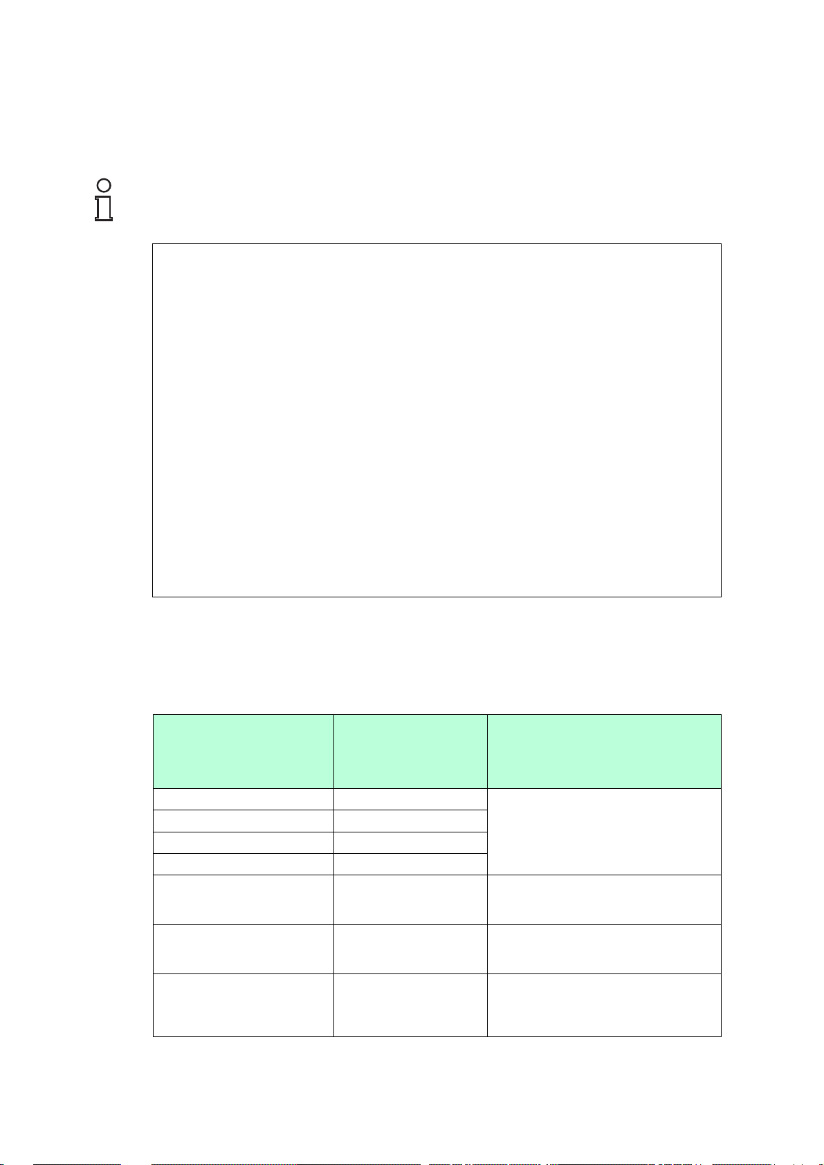
Marking
Bullet WirelesHART Adapter
WHA-BLT-F9D0-N-A0-GP-1
table 1
Pepperl+Fuchs GmbH
Lilienthalstraße 200, 68307 Mannheim, Germany
table 2
Validity
Specific processes and instructions in this instruction manual require
special provisions to guarantee the safety of the operating personnel.
Responsibility for planning, assembly, commissioning, operation,
maintenance, and dismounting lies with the plant operator.
The personnel must be appropriately trained and qualified in order to carry
out mounting, installation, commissioning, operation, maintenance, and
dismounting of the device. The trained and qualified personnel must have
read and understood the instruction manual.
Reference to Further Documentation
Observe laws, standards, and directives applicable to the intended use
and the operating location. Observe Directive 1999/92/EC in relation to
hazardous areas.
The corresponding datasheets, manuals, declarations of conformity, ECtype-examination certificates, certificates, and control drawings if
applicable (see datasheet) are an integral part of this document. You can
find this information under www.pepperl-fuchs.com.
Due to constant revisions, documentation is subject to permanent change.
Please refer only to the most up-to-date version, which can be found under
www.pepperl-fuchs.com.
Intended Use
The device is only approved for appropriate and intended use. Ignoring
these instructions will void any warranty and absolve the manufacturer
from any liability.
Use the device only within the specified ambient temperature range.
The device is used in control and instrumentation technology
(C&I technology) for wireless data transfer from HART devices.
Take the intended use of the connected devices from the corresponding
documentation.
Improper Use
Protection of the personnel and the plant is not ensured if the device is not
used according to its intended use.
Mounting and Installation
Prior to mounting, installation, and commissioning of the device you
should make yourself familiar with the device and carefully read the
instruction manual.
Do not mount the device at locations where an aggressive atmosphere
may be present.
Do not mount a damaged or polluted device.
Avoid electrostatic charges which could result in electrostatic discharges
while installing or operating the device.
The usage of 2400 MHz equipment is bound to local restrictions. Ensure
that local restrictions allow usage of this device before commissioning.
Observe the tightening torque of the screws.
The device provides a grounding terminal to which an equipotential
bonding conductor with a minimum cross section of 4 mm² must be
connected.
Mark permanently the selected type of protection for your specified
application. Use the tick box on the nameplate for that. It is forbidden to
change this marking afterwards.
Ensure that the degree of protection is not violated by the conduit.
Use seals that are suitable for the specified application.
Requirements for Cables and Connection Lines
Install cables and cable glands in a way that they are not exposed to
mechanical hazards.
Protect cables and cable glands from tensile load and torsional stress or
use certified cable glands.
Unused cables and connection lines must be either connected to terminals
or securely tied down and isolated.
Requirements for Cable Glands
Only use cable glands that are suitably certified for the application.
Only use cable glands with a temperature range appropriate to the
application.
For cable glands only use incoming cable diameters of the appropriate
size.
Ensure that the degree of protection is not violated by the cable glands.
Operation, Maintenance, Repair
Do not repair, modify, or manipulate the device.
If there is a defect, always replace the device with an original device.
When the device is in operation, maintain at all times a distance of at least
20 cm to the device antenna. This also applies to any other person in the
vicinity of the device.
Delivery, Transport, Disposal
Check the packaging and contents for damage.
Check if you have received every item and if the items received are the
ones you ordered.
Keep the original packaging. Always store and transport the device in the
original packaging.
Store the device in a clean and dry environment. The permitted ambient
conditions must be considered, see datasheet.
Disposing of device, packaging, and possibly contained batteries must be
in compliance with the applicable laws and guidelines of the respective
country.
DOCT-5061 / 2016-04 1 / 1
Page 5
Instruction Manual
Marking
Bullet WirelesHART Adapter
WHA-BLT-F9D0-N-A0-Z0-Ex1
EC-Type Examination Certificate: FM 11 ATEX 0019 X
II 1 G Ex ia IIC T6/T5 Ga
II 1 D Ex ia IIIC T95 °C Da
Certificate: FM 11 ATEX 0068 X
II 3 G Ex nA IIC T6/T5 Gc
FM approval: CoC3040786(C)
Class I, Zone 0, (A)Ex ia IIC T6/T5 Ga
Class I, Zone 2, (A)Ex nA IIC T6/T5 Gc
Class I, Zone 20, (A)Ex ia IIIC T95°C Da
Class I, Division 1, Groups A - D
Class II, Division 1, Groups E - G
Class III
Class I, Division 2, Groups A - D
IECEx approval: IECEx FMG 11.0010X
Ex ia IIC T6/T5 Ga
Ex nA IIC T6/T5 Gc
Ex ia IIIC T95°C Da
table 1
Pepperl+Fuchs GmbH
Lilienthalstraße 200, 68307 Mannheim, Germany
table 2
Validity
Specific processes and instructions in this instruction manual require
special provisions to guarantee the safety of the operating personnel.
Responsibility for planning, assembly, commissioning, operation,
maintenance, and dismounting lies with the plant operator.
The personnel must be appropriately trained and qualified in order to carry
out mounting, installation, commissioning, operation, maintenance, and
dismounting of the device. The trained and qualified personnel must have
read and understood the instruction manual.
Reference to Further Documentation
Observe laws, standards, and directives applicable to the intended use
and the operating location. Observe Directive 1999/92/EC in relation to
hazardous areas.
The corresponding datasheets, manuals, declarations of conformity, ECtype-examination certificates, certificates, and control drawings if
applicable (see datasheet) are an integral part of this document. You can
find this information under www.pepperl-fuchs.com.
Due to constant revisions, documentation is subject to permanent change.
Please refer only to the most up-to-date version, which can be found under
www.pepperl-fuchs.com.
Intended Use
The device is only approved for appropriate and intended use. Ignoring
these instructions will void any warranty and absolve the manufacturer
from any liability.
Use the device only within the specified ambient temperature range.
The device is used in control and instrumentation technology
(C&I technology) for wireless data transfer from HART devices.
Take the intended use of the connected devices from the corresponding
documentation.
Improper Use
Protection of the personnel and the plant is not ensured if the device is not
used according to its intended use.
Mounting and Installation
Prior to mounting, installation, and commissioning of the device you
should make yourself familiar with the device and carefully read the
instruction manual.
Do not mount the device at locations where an aggressive atmosphere
may be present.
Do not mount a damaged or polluted device.
Avoid electrostatic charges which could result in electrostatic discharges
while installing or operating the device.
If the device has already been operated in general electrical installations,
the device may subsequently no longer be installed in electrical
installations used in combination with hazardous areas.
Observe the installation instructions according to IEC/EN 60079-14.
Connection or disconnection of energized non-intrinsically safe circuits is
only permitted in the absence of a potentially explosive atmosphere.
If circuits with type of protection Ex i are operated with non-intrinsically
safe circuits, they must no longer be used as circuits with type of
protection Ex i.
The usage of 2400 MHz equipment is bound to local restrictions. Ensure
that local restrictions allow usage of this device before commissioning.
Observe the respective peak values of the field device and the associated
apparatus with regard to explosion protection when connecting intrinsically
safe field devices with intrinsically safe circuits of associated apparatus
(verification of intrinsic safety). Also observe IEC/EN 60079-14 and
IEC/EN 60079-25.
Keep the separation distances between all non-intrinsically safe circuits
and intrinsically safe circuits according to IEC/EN 60079-14.
Observe the compliance of the separation distances between two
adjacent intrinsically safe circuits according to IEC/EN 60079-14.
If no Lo and Co values are specified for the simultaneous appearance of
lumped inductances and capacitances, the following rule applies.
l
The specified value for Lo and Co is used if one of the following
conditions applies:
l
The circuit has distributed inductances and capacitances only, e. g., in
cables and connection lines.
l
The total value of Li (excluding cable) of the circuit is < 1 % of the
specified Lo value.
l
The total value of Ci (excluding cable) of the circuit is < 1 % of the
specified Co value.
l
A maximum of 50 % of the specified value for Lo and Co is used if the
following condition applies:
The total value of Li (excluding cable) of the circuit is ≥ 1 % of the
specified Lo value.
The total value of Ci (excluding cable) of the circuit is ≥ 1 % of the
specified Co value.
l
The reduced capacitance for gas groups I, IIA, and IIB must not exceed
the value of 1 µF (including cable). The reduced capacitance for
gas group IIC must not exceed the value of 600 nF (including cable).
Provide a transient protection. Ensure that the peak value of the transient
protection does not exceed 140 % of the rated voltage.
Observe the tightening torque of the screws.
The device provides a grounding terminal to which an equipotential
bonding conductor with a minimum cross section of 4 mm² must be
connected.
Observe the grounding requirements for type of protection Ex i according
to IEC/EN 60079‑14.
The associated apparatus must provide a characteristic which is limited by
a resistor.
Mark permanently the selected type of protection for your specified
application. Use the tick box on the nameplate for that. It is forbidden to
change this marking afterwards.
The device contains aluminum. Thereby the device is considered to
constitute an ignition hazard by impact effect or friction. Avoid impact
effect or friction during mounting and operating.
Ensure that the degree of protection is not violated by the conduit.
Use seals that are suitable for the specified application.
Requirements for Cables and Connection Lines
Observe the permissible cable type and cable length given in the
respective hazardous area certificate.
Regarding the verification of intrinsic safety, observe the maximum
permissible external capacitance of this device and the other devices in
the circuit.
External capacitance C
o
22 µF
table 3
Install cables and cable glands in a way that they are not exposed to
mechanical hazards.
Protect cables and cable glands from tensile load and torsional stress or
use certified cable glands.
Unused cables and connection lines must be either connected to terminals
or securely tied down and isolated.
Requirements for Cable Glands
Only use cable glands that are suitably certified for the application.
Only use cable glands with a temperature range appropriate to the
application.
For cable glands only use incoming cable diameters of the appropriate
size.
Ensure that the degree of protection is not violated by the cable glands.
Operation, Maintenance, Repair
Do not repair, modify, or manipulate the device.
If there is a defect, always replace the device with an original device.
When the device is in operation, maintain at all times a distance of at least
20 cm to the device antenna. This also applies to any other person in the
vicinity of the device.
Delivery, Transport, Disposal
Check the packaging and contents for damage.
Check if you have received every item and if the items received are the
ones you ordered.
Keep the original packaging. Always store and transport the device in the
original packaging.
Store the device in a clean and dry environment. The permitted ambient
conditions must be considered, see datasheet.
Disposing of device, packaging, and possibly contained batteries must be
in compliance with the applicable laws and guidelines of the respective
country.
DOCT-5165 / 2016-04 1 / 1
Page 6

Instruction Manual
Marking
Bullet WirelesHART Adapter
WHA-BLT-F9D0-N-A0-Z1-1
EC-Type Examination Certificate: FM 12 ATEX 0021 X
II 2 G Ex db IIC T6/T5 Gb
II 2 D Ex tb IIIC T95°C Db
FM approval: Coc3041762(C)
Class I, Zone 1, (A)Ex db IIC T6/T5 Gb
Class I, Zone 21, (A)Ex tb IIIC T95°C Db
Class I, Division 1, Groups A - D
Class II, Division 1, Groups E - G
Class III
IECEx approval: IECEx FMG 12.0005X
Ex db IIC T6/T5 Gb
Ex tb IIIC T95°C Db
table 1
Pepperl+Fuchs GmbH
Lilienthalstraße 200, 68307 Mannheim, Germany
table 2
Validity
Specific processes and instructions in this instruction manual require
special provisions to guarantee the safety of the operating personnel.
Responsibility for planning, assembly, commissioning, operation,
maintenance, and dismounting lies with the plant operator.
The personnel must be appropriately trained and qualified in order to carry
out mounting, installation, commissioning, operation, maintenance, and
dismounting of the device. The trained and qualified personnel must have
read and understood the instruction manual.
Reference to Further Documentation
Observe laws, standards, and directives applicable to the intended use
and the operating location. Observe Directive 1999/92/EC in relation to
hazardous areas.
The corresponding datasheets, manuals, declarations of conformity, ECtype-examination certificates, certificates, and control drawings if
applicable (see datasheet) are an integral part of this document. You can
find this information under www.pepperl-fuchs.com.
Due to constant revisions, documentation is subject to permanent change.
Please refer only to the most up-to-date version, which can be found under
www.pepperl-fuchs.com.
Intended Use
The device is only approved for appropriate and intended use. Ignoring
these instructions will void any warranty and absolve the manufacturer
from any liability.
Use the device only within the specified ambient temperature range.
The device is used in control and instrumentation technology
(C&I technology) for wireless data transfer from HART devices.
Take the intended use of the connected devices from the corresponding
documentation.
Improper Use
Protection of the personnel and the plant is not ensured if the device is not
used according to its intended use.
Mounting and Installation
Prior to mounting, installation, and commissioning of the device you
should make yourself familiar with the device and carefully read the
instruction manual.
Do not mount the device at locations where an aggressive atmosphere
may be present.
Do not mount a damaged or polluted device.
Avoid electrostatic charges which could result in electrostatic discharges
while installing or operating the device.
If the device has already been operated in general electrical installations,
the device may subsequently no longer be installed in electrical
installations used in combination with hazardous areas.
Observe the installation instructions according to IEC/EN 60079-14.
The usage of 2400 MHz equipment is bound to local restrictions. Ensure
that local restrictions allow usage of this device before commissioning.
Provide a transient protection. Ensure that the peak value of the transient
protection does not exceed 140 % of the rated voltage.
Observe the tightening torque of the screws.
The device provides a grounding terminal to which an equipotential
bonding conductor with a minimum cross section of 4 mm² must be
connected.
Mark permanently the selected type of protection for your specified
application. Use the tick box on the nameplate for that. It is forbidden to
change this marking afterwards.
The device contains aluminum. Thereby the device is considered to
constitute an ignition hazard by impact effect or friction. Avoid impact
effect or friction during mounting and operating.
Ensure that the degree of protection is not violated by the conduit.
Use seals that are suitable for the specified application.
Requirements for Cables and Connection Lines
Install cables and cable glands in a way that they are not exposed to
mechanical hazards.
Protect cables and cable glands from tensile load and torsional stress or
use certified cable glands.
Unused cables and connection lines must be either connected to terminals
or securely tied down and isolated.
Requirements for Cable Glands
Only use cable glands that are suitably certified for the application.
Only use cable glands with a temperature range appropriate to the
application.
For cable glands only use incoming cable diameters of the appropriate
size.
Ensure that the degree of protection is not violated by the cable glands.
Operation, Maintenance, Repair
Do not repair, modify, or manipulate the device.
If there is a defect, always replace the device with an original device.
When the device is in operation, maintain at all times a distance of at least
20 cm to the device antenna. This also applies to any other person in the
vicinity of the device.
Delivery, Transport, Disposal
Check the packaging and contents for damage.
Check if you have received every item and if the items received are the
ones you ordered.
Keep the original packaging. Always store and transport the device in the
original packaging.
Store the device in a clean and dry environment. The permitted ambient
conditions must be considered, see datasheet.
Disposing of device, packaging, and possibly contained batteries must be
in compliance with the applicable laws and guidelines of the respective
country.
DOCT-5166 / 2016-04 1 / 1
Page 7

1 Introduction................................................................................. 5
BULLET
BULLET WirelessHART® Adapter
User's Manual, December 2017
700-701-96A
www.miinet.com
Moore Industries-International, Inc.
1.1 Contents................................................................................................ 5
1.2 Target Group, Personnel...................................................................... 5
1.3 Symbols Used ...................................................................................... 6
2 Product Specifications............................................................... 7
2.1 Use and Application............................................................................. 7
2.2 Indicators and Operating Elements ................................................... 8
2.3 Scope of Delivery................................................................................. 8
2.4 Storage and Disposal .......................................................................... 9
3 Configuration ............................................................................ 10
3.1 Wired Configuration........................................................................... 10
3.2 Configuration via Device Type Manager (DTM)............................... 11
3.2.1 HART Communication DTM............................................................. 12
3.2.2 Adapter DTM ................................................................................... 14
3.2.3 Online and Offline Parameterization (DTM)...................................... 15
3.2.4 Setup Wizard ................................................................................... 16
3.2.5 Power............................................................................................... 18
3.2.6 Wireless........................................................................................... 20
3.2.7 Wired ............................................................................................... 21
3.2.8 4 ... 20 mA........................................................................................ 23
3.2.9 Burst Settings .................................................................................. 24
3.2.10 Event Notification ............................................................................. 26
3.2.11 Time................................................................................................. 27
3.2.12 Adapter Info ..................................................................................... 28
3.2.13 Battery Info....................................................................................... 29
3.2.14 Alerts ............................................................................................... 30
3.2.15 Device Status................................................................................... 33
3.2.16 Communications.............................................................................. 34
3.2.17 Maintenance .................................................................................... 35
3.2.18 Device Info....................................................................................... 37
3.3 Configuration via Device Description (DD) ..................................... 37
Page 8

BULLET
BULLET WirelessHART® Adapter
User's Manual, December 2017
700-701-96A
www.miinet.com
Moore Industries-International, Inc.
User's Manual, December 2017
4 Installation................................................................................. 40
4.1 Mounting Considerations ..................................................................40
4.1.1 Positioning the Device ......................................................................40
4.1.2 Examples for Good and Poor Positioning ......................................... 41
4.1.3 Installation Options........................................................................... 42
4.2 Explosion-Hazardous and Non-Explosion Hazardous Areas ........43
4.3 Wiring ..................................................................................................43
4.3.1 Field Wiring ...................................................................................... 43
4.3.2 Grounding ........................................................................................44
4.4 Installation on Field Device ............................................................... 46
4.5 Installation as Stand-Alone Router ................................................... 49
4.6 Multidrop Mode................................................................................... 52
5 Operation................................................................................... 52
5.1
6 Troubleshooting........................................................................
Control Drawings & Certifications........................................
7
HART Variables ...................................................................................52
53
59
Page 9

1Introduction
BULLET
BULLET WirelessHART® Adapter
User's Manual, December 2017
700-701-96A
www.miinet.com
Moore Industries-International, Inc.
1.1 Contents
This document contains information that you need in order to use your product throughout the
applicable stages of the product life cycle. These can include the following:
■ Product identification
■ Delivery, transport, and storage
■ Mounting and installation
■ Commissioning and operation
■ Maintenance and repair
■ Troubleshooting
■ Dismounting
■ Disposal
Note!
You can obtain detailed BULLET part number and
ordering information from the BULLET data sheet which
is available for download from the Moore Industries web
site, www.miinet.com.
1.2 Target Group, Personnel
2015-12
Responsibility for planning, assembly, commissioning, operation, maintenance, and
dismounting lies with the plant operator.
Only appropriately trained and qualified personnel may carry out mounting, installation,
commissioning, operation, maintenance, and dismounting of the product. The personnel must
have read and understood the instruction manual and the further documentation.
Prior to using the product make yourself familiar with it. Read the document carefully.
5
Page 10
1.3
BULLET
BULLET WirelessHART® Adapter
User's Manual, December 2017
700-701-96A
www.miinet.com
Moore Industries-International, Inc.
Symbols Used
This document contains symbols for the identification of warning messages and of informative
messages.
Warning Messages
You will find warning messages in instances, whenever dangers may arise from your actions. It
is mandatory that you observe these warning messages for your personal safety and in order to
avoid property damages.
Depending on the risk level, the warning messages are displayed in descending order as
follows:
Danger!
This symbol indicates an imminent danger.
Non-observance will result in personal injury or death.
Warning!
This symbol indicates a possible fault or danger.
Non-observance may cause personal injury or serious property damage.
Caution!
This symbol indicates a possible fault.
Non-observance could interrupt the device and any connected systems and plants, or result in
their complete failure.
Informative Symbols
Note!
This symbol brings important information to your attention.
Action
This symbol indicates a paragraph with instructions. You are prompted to perform an action or
a sequence of actions.
6
2015-12
Page 11

2 Product Specifications
BULLET
BULLET WirelessHART® Adapter
User's Manual, December 2017
700-701-96A
www.miinet.com
Moore Industries-International, Inc.
2.1 Use and Application
The Bullet WirelessHART Adapter enables up to 8 HART field devices or analog field devices
(with no HART capability) to communicate with host applications by means of WirelessHART
technology. The adapter can be attached directly to a spare connection of a field device or
anywhere on the 4 ... 20 mA current loop. Once a HART field device is equipped with an
adapter, it communicates its primary variable (PV) over the existing wire and simultaneously
communicates the primary variable (PV), secondary variable (SV), tertiary variable (TV),
quaternary variable (QV) as well as diagnostic and alarm data over the WirelessHART network.
The adapter can be supplied by the existing current loop or by an external power supply, such
as, a battery.
■ When loop powered, the adapter saves users the long-term cost of battery maintenance,
replacement and disposal programs. The patent pending StepVolt
TM
technology enables
you to set the insertion voltage in steps from 1 ... 2.5 V.
■ When battery powered, the adapter provides battery power management by switching the
attached field devices on and off as needed.
2015-12
The device is used in control and instrumentation technology (C&I technology) for wireless data
transfer from HART devices.
The device is only approved for appropriate and intended use. Ignoring these instructions will
void any warranty and absolve the manufacturer from any liability.
Protection of the personnel and the plant is not ensured if the device is not being used
according to its intended use.
Take the intended use of the connected devices from the corresponding documentation.
Use the device only within the specified ambient and operating conditions.
The usage of 2400 MHz equipment is bound to local restrictions. Ensure that local restrictions
allow usage of this device before commissioning.
7
Page 12
Country Guideline
1
2
3
BULLET
BULLET WirelessHART® Adapter
User's Manual, December 2017
700-701-96A
www.miinet.com
Moore Industries-International, Inc.
Bulgaria General authorization required for outdoor use
Italy If used outside of own premises, general
Japan The device is granted pursuant to the
Latvia The outdoor usage of the 2.4 GHz band
Norway May be restricted in the geographical area
Romania
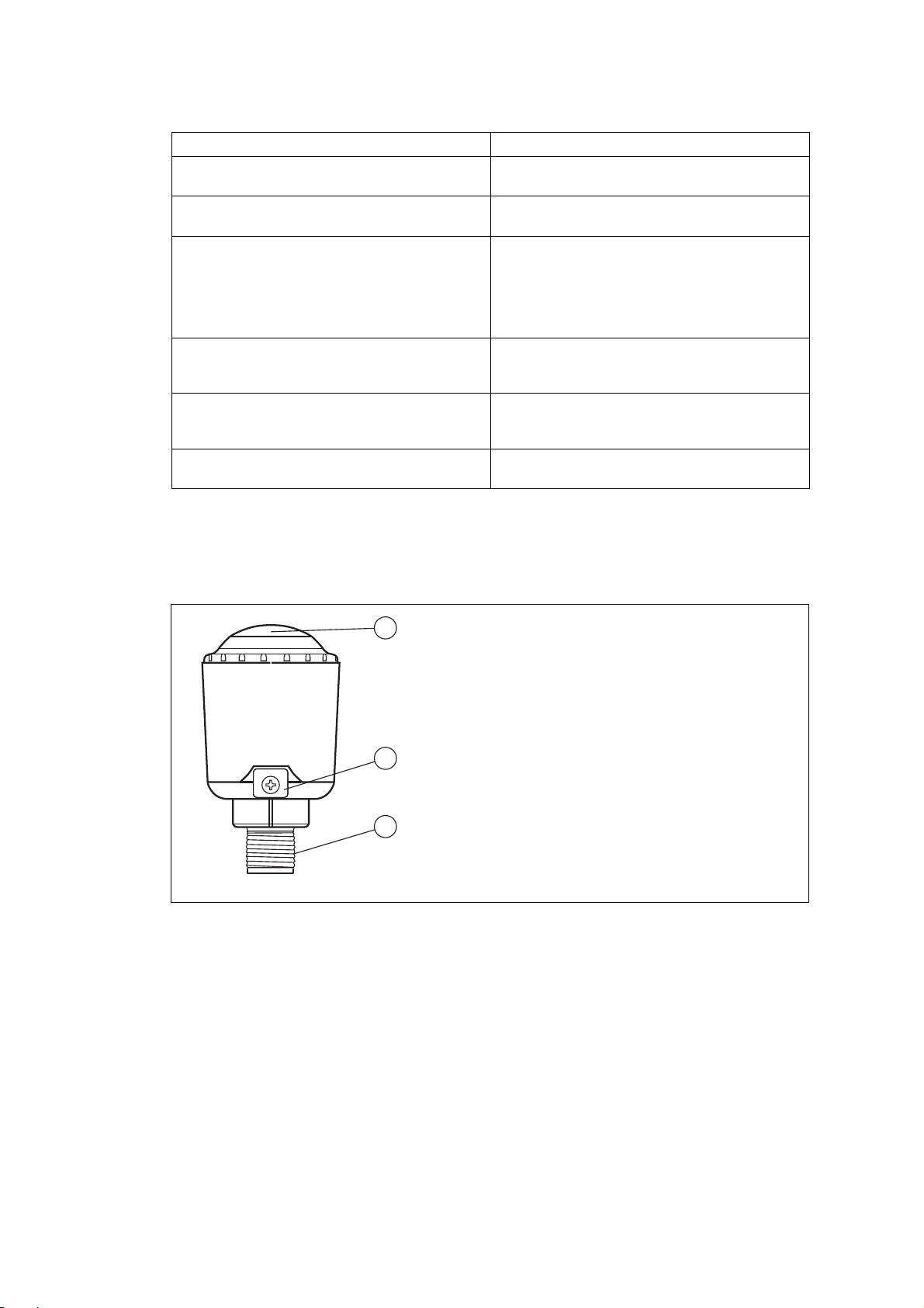
2.2 Indicators and Operating Elements
The adapter has both a radio interface to communicate with the WirelessHART network and a
wired HART interface to communicate with HART field devices and analog field devices (with
no HART capability) on the 4 ... 20 mA current loop.
and public service.
authorization is required.
Japanese Radio Law and the Japanese
Telecommunications Business Law.
The device must not be modified (otherwise
the granted designation number will become
invalid).
requires an authorization from the Electronic
Communications Office.
within a radius of 20 km from the center of NyAlesund.
Use on a secondary basis. Individual license
required.
2.3 Scope of Delivery
Check the packaging and contents for damage.
Check if you have received every item and if the items received are the ones you ordered.
8
1. Encapsulated antenna
2. Grounding point
3. Male ½ inch NPT thread for installation on field device
■ Bullet WirelessHART
®
Adapter
11010z-x0M0
z = 0,1,2 and x=8 or P
Refer to data sheet for more
information
2015-12
Page 13

2.4 Storage and Disposal
BULLET
BULLET WirelessHART® Adapter
User's Manual, December 2017
700-701-96A
www.miinet.com
Moore Industries-International, Inc.
Keep the original packaging. Always store and transport the device in the original packaging.
Store the device in a clean and dry environment. The permitted ambient conditions
(see datasheet) must be considered.
Disposing of device, packaging, and possibly contained batteries must be in compliance with
the applicable laws and guidelines of the respective country.
2015-12
9
Page 14

3 Configuration
mA
+
-
BULLET
BULLET WirelessHART® Adapter
User's Manual, December 2017
700-701-96A
www.miinet.com
Moore Industries-International, Inc.
3.1 Wired Configuration
Configure the adapter on the shop floor using a wired connection prior to its installation in the
field.
1. Define basic settings, such as, wireless communication parameters and identification parameters using a HART modem.
2. Make the adapter join the WirelessHART network.
3. Once the adapter has joined the WirelessHART network, configure the burst settings and
other application settings using a HART modem.
4. Disconnect the HART modem and install the adapter in the field.
Caution!
Loss of type of protection
If circuits with type of protection Ex i are operated with non-intrinsically safe circuits, they must
no longer be used as circuits with type of protection Ex i.
When configuring an adapter with type of protection Ex i, use a HART modem with type of
protection Ex i to communicate with the adapter.
Caution!
Damage due to overcurrent
A current that exceeds the operating specifications of the device can cause damage to the
device.
Ensure that the supplied current never exceeds 32 V DC.
Setup for Wired Configuration
1. Connect the black conductor (Direct Power) to the positive terminal (+) of the power supply
and the white conductor (Return) to the negative terminal (-) of the power supply.
2. Connect the HART modem to the yellow conductor (HART) and white conductor (Return) of
the adapter. The HART connection is polarity independent.
3. Make sure the red conductor (Loop Power) of the adapter is not connected to the power
supply or ground connection.
4. Turn on the power supply. Make sure the adapter is supplied with 7 ... 32 V DC.
10
The adapter is ready to be configured.
2015-12
Page 15
3.2
BULLET
BULLET WirelessHART® Adapter
User's Manual, December 2017
700-701-96A
www.miinet.com
Moore Industries-International, Inc.
Configuration via Device Type Manager (DTM)
Once the adapter is connected to a HART modem, you can configure the adapter using a
PC that has an FDT frame application installed, for example, PACTwareTM. Furthermore,
the HART communication DTM and the DTM of the adapter must be installed on the PC.
Install Components
1. Download the latest version of PACTware, from http://www.miinet.com/ and the
HART communication DTM and the DTM of the adapter on the BULLET product
page.
2. and the HART communication DTM and the DTM of the adapter at http://
www.miinet.com/InterfaceSolutionDownloadCenter/Products.aspx?product=244
Create New Project?
1. Start PACTware.
2. Select File > New or click Create New Project.
A new, unnamed project appears in the main window. The project initially consists of the
entry HOST PC.
Update Device Catalog
1. Select View > Device Catalog.
The Device Catalog window opens.
2. Click Update Device Catalog to update the device catalog.
3. Click Ye s to continue.
The device catalog has been updated and newly installed components, such as the
HART communication DTM and the DTM of the adapter have been integrated into the
catalog.
2015-12
11
Page 16

3.2.1 HART Communication DTM
BULLET
BULLET WirelessHART® Adapter
User's Manual, December 2017
700-701-96A
www.miinet.com
Moore Industries-International, Inc.
A communication DTM is an interface between the FDT frame application and the DTM of the
device.
For the PC to communicate with the device via the HART modem, a HART communication
DTM has to be added to the PACTware project.
Add HART Communication DTM
1. Select HOST PC in the project view of your PACTware project.
2. Choose Device > Add device or click the Add device icon on the toolbar.
The Device for window appears.
Figure 3.1 Device selection
3. Select HART communication.
4. Click OK.
The HART communication DTM is added to the project.
Figure 3.2 Project view
5. To edit the parameters, double-click the HART communication DTM.
The parameter window appears.
12
2015-12
Page 17
Figure 3.3 Parameter window
BULLET
BULLET WirelessHART® Adapter
User's Manual, December 2017
700-701-96A
www.miinet.com
Moore Industries-International, Inc.
6. Set the parameters according to the following table.
7. Click OK to save the changes and to close the parameter window.
Parameter Description Default
Communication
interface
Set this parameter to HART modem. HART
modem
Port Select the COM port that your HART modem is connected to. COM1
Master The adapter is configured as a primary master. Therefore the
device used to configure the adapter should be configured as
Primary
Master
secondary master.
Set this parameter to Secondary Master.
Preamble Number of preambles for HART communication. 5
Number of
The number of retries in case of an error. 3
communication
retries
Start address Defines the address range, in which the HART communication
End address 0
DTM searches for HART devices connected to the HART
modem.
0
The default polling address of the adapter is 15.
Communication
timeout
If no communication takes place during this time frame, the
connection is reestablished unless the number of
2
communication retries is used up.
Multimaster and
Enables support for multiple masters and burst mode. Activated
Burst mode
support
2015-12
13
Page 18
3.2.2 Adapter DTM
BULLET
BULLET WirelessHART® Adapter
User's Manual, December 2017
700-701-96A
www.miinet.com
Moore Industries-International, Inc.
After you have added a communication DTM, add the adapter DTM to the PACTware project.
Add Adapter DTM
1. In the project view, right-click the HART communication DTM.
Figure 3.4 Project view
2. To add the adapter DTM, choose Add device from the context menu.
The Device for window opens.
Figure 3.5 Device selection
3. Select Bullet HART DTM.
4. Click OK.
The adapter is added to the project. Now you can configure the adapter as if you had a
wired connection.
Figure 3.6 Project view
5. Right-click the adapter DTM.
6. Select Additional Functions > Communication.
7. Select the polling address 15 and click Apply.
2015-12
14
Page 19
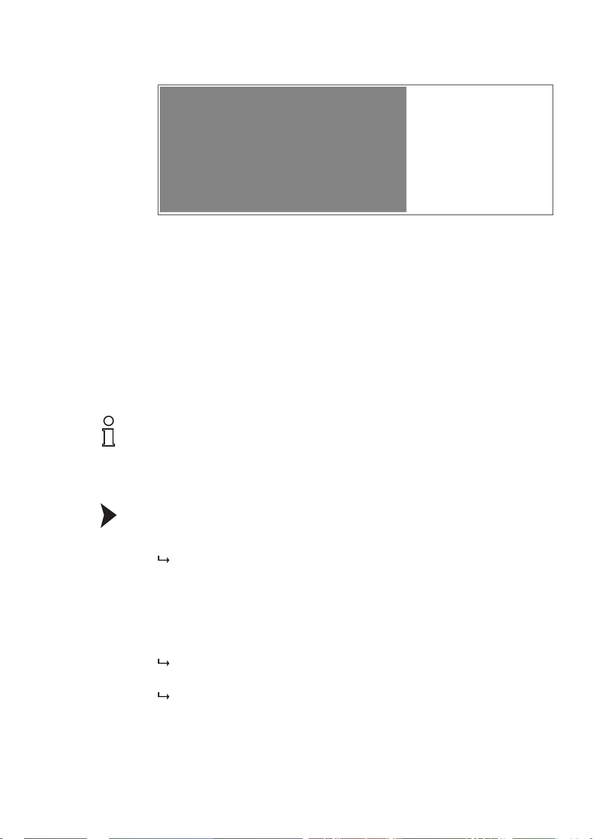
Figure 3.7 Set polling address
BULLET
BULLET WirelessHART® Adapter
User's Manual, December 2017
700-701-96A
www.miinet.com
Moore Industries-International, Inc.
8. Click Close.
3.2.3 Online and Offline Parameterization (DTM)
The concept of online and offline parameterization applies only to configuration via DTM and
PAC Twa re .
■ Offline Parameterization (not connected to device)
If there is no active connection to the device, you can edit and save the data that is stored
locally in PACTware. You can transfer the local data to the device, as soon as a connection
to the device has been established.
■ Online Parameterization (connected to device)
If there is an active connection to the device, you can directly edit the data that is stored
on the device. Parameter changes are immediately stored on the device.
Note!
Data that is edited and stored on the device during online parameterization is not automatically
synchronized with the offline data in the PACTware project. If you change device parameters in
online mode, the data in PACTware differs from the data on the device. To make sure the data in
PACTware matches the data on the device after online parameterization, load the data from the
device into the PACTware project.
Offline Parameterization
1. Right-click the device in the PACTware project view.
2. Choose Parameter > Offline Parameterization.
The window containing the offline data record appears.
3. Modify a parameter by typing in a new value or choosing a new value from the drop-down
list.
4. To accept the new value, press Enter.
5. After all parameter changes have been made, save your project by choosing File > Save.
6. To write the new offline configuration to the device, right-click the device in the project view
and choose Connect.
A connection to the device is established.
7. Right-click the device again and choose Store to device.
The new configuration is stored in the device.
2015-12
15
Page 20
Online Parameterization
BULLET
BULLET WirelessHART® Adapter
User's Manual, December 2017
700-701-96A
www.miinet.com
Moore Industries-International, Inc.
Note!
Some options are only available during online parameterization. These options are pointed out
in the relevant sections.
1. Right-click the device in the PACTware project view.
2. Select Connect.
A connection to the device is established.
3. Right-click the device in the PACTware project view.
4. Select Parameter > Online Parameterization.
The window containing the online data opens and the data is read from the device.
5. Modify a parameter by typing in a new value or choosing a new value from the drop-down
list.
6. To accept the new value, press Enter.
The new value is stored in the device immediately.
7. After all parameter changes have been made, you can load the online configuration into the
PACTware project. To do this, right-click on the device entry in the project view and choose
Load from device.
8. Save your project by choosing File > Save.
3.2.4 Setup Wizard
The setup wizard enables you to define basic parameters, such as, network ID and join key.
Note!
This submenu is available only during online parameterization.
Run Setup Wizard
1. Right-click the adapter DTM.
2. Select Connect.
16
Figure 3.8 Connect to device
2015-12
Page 21

3. To edit the parameters, double-click the adapter DTM.
BULLET
BULLET WirelessHART® Adapter
User's Manual, December 2017
700-701-96A
www.miinet.com
Moore Industries-International, Inc.
The Online Parameterization window opens with the Adapter Overview screen.
Figure 3.9 Adapter Overview
4. Select Setup Wizard.
Figure 3.10 Setup Wizard
2015-12
5. The setup wizard enables you to define the tag, the long tag, the way the adapter is
supplied, as well as the network settings.
For more information on the available options, see the following chapters.
17
Page 22
3.2.5 Power
BULLET
BULLET WirelessHART® Adapter
User's Manual, December 2017
700-701-96A
www.miinet.com
Moore Industries-International, Inc.
This submenu enables you to define the way the adapter is supplied.
Note!
This submenu is available only during online parameterization.
Figure 3.11 Power options
Adapter Power Setting
By default, the adapter is loop powered with an insertion voltage drop of 1 V DC.
The following options are available.
WirelessHART Packets
per Second
(as reported by HART
Option
command 777)
Loop Powered - 1.0 V 4.25
Loop Powered - 1.5 V 12.65
Loop Powered - 2.0 V 19.66
Loop Powered - 2.5 V 26.66
Direct Powered - Max
101.40 Provides maximum bandwidth,
Bandwidth
Direct Powered - Power Save 26.66 Limits the number of WirelessHART
Direct Powered - Battery 26.66 Assumes that the power supply is a
Description
Ste pVoltTM settings when loop
powered
assuming the powers supply supplies
32 V
data packets, assuming the power
supply is limited
battery and enables the battery
management functions, such as,
battery life calculations and alerts
18
2015-12
Page 23

The adapter can be supplied by an external DC powers supply and wired in series with the
BULLET
BULLET WirelessHART® Adapter
User's Manual, December 2017
700-701-96A
www.miinet.com
Moore Industries-International, Inc.
4 ... 20 mA current loop at the same time. If the adapter is configured in any of the Direct
Power options and wired in series with the current loop, there will be an insertion voltage drop
of 1.0 V DC.
Warning!
Field device failure due to insufficient power supply
TM
If the adapter has an internal failure and stops regulating the StepVolt
value, the maximum
insertion voltage drop can rise up to 4.935 V DC.
Note!
The adapter will power up and operate with any configuration. This enables you to change the
configuration of an incorrectly configured device. However, you should change the power
options before the adapter joins the WirelessHART network. Once the adapter joins the
WirelessHART network it might reset itself due to insufficient power supply.
Field Device Power Control
If the adapter is directly powered by an external current source, the adapter can activate a
terminator of 250 between the HART and the RETURN conductors. In some installations this
can eliminate the need for an external terminator.
The Field Device Power Control option allows you to control the power supply for the field
devices by switching them on and off. The following options are available.
■ Off
Power supply for field devices is switched off.
■ On
Power supply for field devices is switched on.
■ Switching
Power supply for field devices is automatically switched on and off by the adapter.
When Switching is enabled, the adapter switches the field devices on and off as needed. This
can be used to switch off a field device between measurements, of example, if the field device
is supplied by a limited power supply, such as, a battery.
When used in combination with burst mode, the adapter schedules measurements from the
field devices, and turns them on when a scheduled measurement is needed. After all
measurements have been read from the field devices, the adapter turns off the supply for the
field devices.
Note that the Field Device Turn On Time must be sufficiently long, in order to obtain accurate
measurements from the field devices. Otherwise, the field device may not have enough time to
power up, initialize and respond with a correct measurement value before the power supply is
switched off again.
The Field Device Idle Time is the duration for which a field device remains powered after an
unscheduled event. Such events could be a HART query from a handheld or the detection of
another HART master trying to communicate with the field device. This option prevents the
adapter from switching off the field device when another master communicates with the field
device.
2015-12
Field Device On Estimated Percent displays the estimated time that the field device is
supplied during normal operation. The calculation is based on the Field Device Turn On Time
and the burst mode settings of the adapter.
19
Page 24

Field Device Cutoff Enable enables the adapter to turn off the power supply for field devices
BULLET
BULLET WirelessHART® Adapter
User's Manual, December 2017
700-701-96A
www.miinet.com
Moore Industries-International, Inc.
when the power of the power supply drops below the value that is defined in the Field Device
Cutoff Voltage field. To use this option, Field Device Power Control must be set to On or
Switching.
Note that there is a built-in 0.5 V hysteresis for the Field Device Cutoff Voltage.
Note!
Battery-Powered Operation
If the adapter is loop powered, the adapter and field devices are continuously powered on. If
the adapter is directly powered, the adapter can switch the field devices on and off, which
results in a prolonged battery life.
In order to manage the battery power, the Field Device Power Control option must be set to
On. This enables you to define the Field Device Turn On Time and Field Device Idle Time
as required by the field device for correct operation and as required by the application.
See chapter 3.2.13
3.2.6 Wireless
This submenu enables you to define the network settings for joining the WirelessHART
network.
Note!
This submenu is available only during online parameterization.
Figure 3.12 Wireless options
Wireless Connection
The Network ID is the identifier of the WirelessHART network to join.
The Join Key is a 32 character hexadecimal password that is used to access the
WirelessHART network.
20
2015-12
Page 25
The Join Mode defines when the adapter should connect itself to the WirelessHART network.
BULLET
BULLET WirelessHART® Adapter
User's Manual, December 2017
700-701-96A
www.miinet.com
Moore Industries-International, Inc.
The following options are available.
■ Don't attempt to join
Do not connect to the WirelessHART network.
■ Join Now
Manually connect to the WirelessHART network.
■ Attempt to join immediately on powerup or reset
Automatically connect to the WirelessHART network.
Danger!
Explosion hazard
If the emitted power level is too high, a potentially explosive atmosphere can ignite
■ Respect the limitations for explosion-hazardous areas.
■ Respect local restrictions for usage of 2400 MHz equipment. If in doubt, consult your
national regulations expert.
The Radio Output Power defines the power level of the radio transmitter. This option can be
set to either 0dBm (1.3 mW) or +10 dBm (10 mW).
Radio Upgrade
If Over the Air Upgrade is enabled, the device data can be updated over the WirelessHART
network.
3.2.7 Wired
This submenu enables you to define the settings for communicating with HART field devices.
Note!
This submenu is available only during online parameterization.
2015-12
Figure 3.13 Wired options
21
Page 26

HART
BULLET
BULLET WirelessHART® Adapter
User's Manual, December 2017
700-701-96A
www.miinet.com
Moore Industries-International, Inc.
The Master Mode defines whether the adapter acts as a primary or a secondary master when
communicating with HART field devices.
The Retry Count defines how often the adapter retries to communicate with HART field
devices as a HART master.
The Polling Address defines the HART polling address that is used to communicate with the
adapter over a wired HART connection, for example, using a HART modem.
Sub-Device Scan
When Sub-Device Scan On Power-up is enabled, the adapter scans the 4 ... 20 mA current
loop for HART field devices on power-up and after a reset. The HART field devices that have
been detected are added to the list of sub-devices and can be accessed over the
WirelessHART network.
We recommend, that you leave this option enabled. If disabled, the host must support scanning
for sub-devices or you must initiate the scan manually by clicking Scan for Devices.
Furthermore, each time the adapter is powered-up or reset, the list of sub-devices is lost and
the network must be rescanned.
Note!
The scan for sub-devices is performed only during power-up or reset of the adapter. If an
additional field device is added to the current loop while the adapter is in normal operation, you
must reset the adapter or initiate the scan manually by clicking Scan for Devices to detect the
new field device.
Scan Start Address designates the first HART polling address that is used when scanning for
sub-devices.
Scan Stop Address designates the last HART polling address that is used when scanning for
sub-devices.
If Sub-Device Time Sync is enabled, the adapter can synchronize the sub-device time with
the WirelessHART network time for HART devices supporting HART 7 or greater. If the subdevice does not support a real-time clock, this option has no effect. Synchronization is
performed once a day.
22
2015-12
Page 27

3.2.8 4 ... 20 mA
BULLET
BULLET WirelessHART® Adapter
User's Manual, December 2017
700-701-96A
www.miinet.com
Moore Industries-International, Inc.
When the adapter is connected to an analog field device (with no HART capability), the adapter
can measure the current on the 4 ... 20 mA current loop. The adapter can convert the
measured value into another engineering unit and communicate the result as primary variable
(PV) over the WirelessHART network.
Note!
This submenu is available only during online parameterization.
Figure 3.14 4 ... 20 mA options
4...20mA
PV Units defines the unit that the primary variable (PC) is reported as.
The PV Linearization Mode enables you to define different linearization tables for the
measured values. The following options are available.
■ Linear
A basic linear calculation will be performed to convert the measured values. The PV
Upper Range Value and the PV Lower Range Value correspond to the 4 ... 20 mA
points.
■ Special Curve
This option enables you to define individual linearization tables. Click PV Linearization
Ta b l e to enter data pairs for mapping a current value of the 4 ... 20 mA current loop to
another engineering unit. The table must have at least two data pairs and can have up to
32 pairs.
PV Damp defines the attenuation value in seconds that is applied to the PV.
If the current on the 4 ... 20 mA current loop exceeds the Upper Fault Current, the adapter
sets a HART loop current alarm.
If the current on the 4 ... 20 mA current loop falls below the Lower Fault Current, the adapter
sets a HART loop current error.
2015-12
23
Page 28

If the current on the 4 ... 20 mA current loop exceeds the Upper Limit of Proportional Range,
BULLET
BULLET WirelessHART® Adapter
User's Manual, December 2017
700-701-96A
www.miinet.com
Moore Industries-International, Inc.
the adapter sets a HART loop current warning.
If the current on the 4 ... 20 mA current loop falls below the Lower Limit of Proportional
Range, the adapter sets a HART loop current warning.
3.2.9 Burst Settings
Burst settings enable the adapter to publish data in regular intervals without being polled by a
host.
Note!
This submenu is available only during online parameterization.
24
Figure 3.15 Burst options
Auto Burst
When automatic configuration is enabled, the adapter automatically configures the burst
messages for the adapter and all of the connected sub-devices.
The Automatic Update Rate enables you to define a fixed update rate. The following options
are available.
■ Off
Disable automatic configuration of burst settings.
■ 1 ... 32 seconds
Select an update rate between 1 and 32 seconds in which all of the burst messages will
be published to the WirelessHART gateway.
■ 1 ... 60 minutes
Select an update rate between 1 and 60 minutes in which all of the burst messages will be
published to the WirelessHART gateway.
Select the commands that will be used for automatic configuration from the Automatic
Commands drop-down list.
2015-12
Page 29

Click Apply Auto Burst to enable automatic configuration.
BULLET
BULLET WirelessHART® Adapter
User's Manual, December 2017
700-701-96A
www.miinet.com
Moore Industries-International, Inc.
Note!
If automatic configuration is enabled while a manual configuration has already been activated,
the manual configuration is overwritten.
If a manual configuration is activated while an automatic configuration has already been
enabled, the automatic configuration is disabled.
Manual Burst
To define the burst settings manually, double-click a row in the Manual Burst table. In the
Burst Message Setting window you can define the commands, trigger options, and update
periods for each burst message.
2015-12
Figure 3.16 Burst Message Setting window
Click Apply Manual Burst to activate the manual configuration.
25
Page 30

3.2.10 Event Notification
BULLET
BULLET WirelessHART® Adapter
User's Manual, December 2017
700-701-96A
www.miinet.com
Moore Industries-International, Inc.
The adapter detects and logs different event messages. This submenu enables you to activate
or deactivate selected standard events and device-specific events.
Note!
This submenu is available only during online parameterization.
Figure 3.17 Event notification options
Select Event Status in the navigation area on the left, to see the current status of the selected
events.
26
Figure 3.18 Event status overview
2015-12
Page 31

3.2.11 Time
BULLET
BULLET WirelessHART® Adapter
User's Manual, December 2017
700-701-96A
www.miinet.com
Moore Industries-International, Inc.
This submenu displays the current time of the internal clock of the adapter as well as the
uptime of the adapter.
Note!
This submenu is available only during online parameterization.
Figure 3.19 Current time and uptime
2015-12
27
Page 32

3.2.12 Adapter Info
BULLET
BULLET WirelessHART® Adapter
User's Manual, December 2017
700-701-96A
www.miinet.com
Moore Industries-International, Inc.
This submenu enables you to define the identification parameters to identify the adapter within
the WirelessHART network.
Note!
This submenu is available only during online parameterization.
Figure 3.20 Adapter identification options
Adapter Information
The Ta g identifies the field device within the process plant. Enter up to 8 characters.
The Long Tag identifies the device in a WirelessHART network. Enter up to 32 characters.
The Descriptor contains a description of the device. Enter up to 16 characters.
The Message field enables you to define a device-specific message. Enter up to 32
characters.
The Final Assembly Num field enables you to enter an identifier for the connected field
device.
The Date field enables you to enter a date. Use the following date format dd/mm/yyyy.
The Country field enables you to define the country of installation.
The SI Unit Control field enables you to select whether you want to use only SI units, for
example, for converting a current value on the 4 ... 20 mA current loop into another engineering
unit.
The Electronics Temperature field enables you to define whether you want to use the
Celsius, Fahrenheit, or Kelvin scale for temperatures.
Write Protected
If Write Protected is enabled, the configuration of the adapter cannot be changed. The factory
default setting is Disabled. If you changed this option, click Apply to apply the current setting.
28
2015-12
Page 33

3.2.13 Battery Info
BULLET
BULLET WirelessHART® Adapter
User's Manual, December 2017
700-701-96A
www.miinet.com
Moore Industries-International, Inc.
If the adapter is supplied by an external battery, this submenu enables you to define basic
battery settings and to monitor battery consumption.
To determine the remaining battery life, the adapter employs the battery voltage and the battery
coulomb discharge rate. Both variables are continuously monitored.
Note!
This submenu is available only during online parameterization.
Figure 3.21 Battery options
Battery Settings
Enter the capacity of the battery in mAh in the Battery Capacity field. This value is used by the
Coulomb algorithm to determine the remaining battery life in days.
If the voltage falls below the Battery Low Voltage, the power status is set to Low and the
remaining battery life is set to 25 days or less. This value is used as an independent check
beside the Coulomb algorithm.
If the voltage falls below the Battery Critical Voltage, the power status is set to Critical and
the remaining battery life is set to 0 days. This value is used as an independent check beside
the Coulomb algorithm.
Enter the date of the battery change in the Battery Changed Date field. Use the following date
format dd/mm/yyyy. The battery counter is reset on this date.
2015-12
29
Page 34

Battery Stats
BULLET
BULLET WirelessHART® Adapter
User's Manual, December 2017
700-701-96A
www.miinet.com
Moore Industries-International, Inc.
WirelessHART defines 3 power status levels for battery powered devices.
1. Nominal
The power supply is operating correctly.
2. Low
The power supply should be exchanged when the low indication is set.
3. Critical
The power supply should be exchanged immediately. Otherwise, an interruption of the
power supply will happen in the immediate future.
The current battery ratings are displayed below the Power Status.
3.2.14 Alerts
The adapter detects and logs system events when something has occurred that could affect
system operation. All alerts are mapped into HART command 48 status bits.
Note!
This submenu is available only during online parameterization.
Figure 3.22 Alerts
30
2015-12
Page 35

Alerts are divided into active and historic alerts.
BULLET
BULLET WirelessHART® Adapter
User's Manual, December 2017
700-701-96A
www.miinet.com
Moore Industries-International, Inc.
■ Active alerts are displayed on the Active tab. The condition that caused the alert is still
present. Active alerts cannot be cleared. A corrective action must be taken to eliminate
the alert, for example, if the power status of an external battery is Low, the battery must be
exchanged to clear the alert.
■ Historic alerts are displayed on the History tab. The condition that caused the alert is no
longer present, or the alert is a one-time event. The Start Date and Start Tim e indicate
when the condition first occurred and the Stop Date and Stop T i me indicate when the
condition stopped, or the last time that the condition was detected.
Click Clear to eliminate the alert history.
Alerts
Alert Description Corrective Action
Direct Power Out of Range The adapter is configured for
direct power (external power
Check the external power
supply.
supply) and the voltage on the
input is out of range.
Loop Power Out of Range The adapter is configured to
be loop powered and the
Check the current on the
4 ... 20 mA current loop.
voltage on the input is out of
range.
Temperature Out of Range The Electronics
Te m pe r a tu r e is out of range.
See chapter 3.2.14
Power Mode Misconfigured The power supply detected on
the inputs does not match the
Check whether the adapter is
used within the specified
ambient conditions.
Check the power options. See
chapter 3.2.5
configuration.
Watchdog Reset The microprocessor inside of
the adapter has experienced a
watchdog reset event.
Stack Overflow The microprocessor inside of
the adapter has experienced a
stack overflow event.
Duplicate HART Master
Detected
A HART master has been
detected that has the same
master type as the adapter.
This prevents the adapter form
communicating with the
connected sub-devices.
HART Devices Count
Exceeded
A HART master has been
detected that has the same
master type as the adapter.
This prevents the adapter form
communicating with the
connected sub-devices.
HART Sub-Device Lost A sub-device has stopped
communicating with the
adapter and has been
dropped from the sub-device
Clear the alert. Report the
event to customer support.
Clear the alert. Report the
event to customer support.
Check the Master Mode of
the adapter. If using a HART
Handheld, make sure it is not
set for the same master type
as the adapter. See chapter
3.2.7
Check the Master Mode of
the adapter. If using a HART
Handheld, make sure it is not
set for the same master type
as the adapter. See chapter
3.2.7
If the sub-device was removed
intentionally, clear the alert.
Otherwise, check the wiring of
the sub-device.
list.
2015-12
31
Page 36

Alert Description Corrective Action
BULLET
BULLET WirelessHART® Adapter
User's Manual, December 2017
700-701-96A
www.miinet.com
Moore Industries-International, Inc.
Burst Packets are Being
Dropped
One or more burst data
packets have been dropped.
Check whether the
WirelessHART network has
granted the requested
bandwidth for the burst
messages. If not, you can
either adjust the
WirelessHART network
settings or adjust the burst
times of the adapter.
If the burst messages were
intended for the connected
sub-devices, make sure there
are no other HART masters on
the connection, as these can
cause burst message delays.
Field Device Power Control This alert is set, whenever
Field Device Power Control
is set to Switching and the
Field Device On Estimated
Percent is 100 because the
burst settings keep the subdevice always powered on.
If the Switching option is not
required, change this option.
Otherwise, reduce the burst
times for the connected subdevice and check the variation
of the Field Device On
Estimated Percent value.
See chapter 3.2.5
Wireless Capacity Denied The WirelessHART network
has denied a request for
wireless bandwidth.
Burst Message Configuration
Issue
A burst message is configured
to a command that is not
supported by the selected
sub-device.
Wired Device in Burst Mode A connected sub-device is
configured for wired burst
Check the burst settings and
reduce the requested
bandwidth.
Change the command
number of the burst message
to a command that is
supported by the sub-device.
Disable wired burst mode of
the connected sub-device.
mode, which may conflict with
burst settings of the adapter.
Adapter Failed to Join the
Network
Radio Malfunction The radio module inside the
Variable Simulation One or more of the device
Field Device Cutoff Occurred This alert is set, whenever
The adapter has failed to join
the WirelessHART network.
adapter is malfunctioning.
variables are being simulated.
Field Device Cutoff Enable
Check the network ID and join
key. See chapter 3.2.6
Report this issue to
Customer Support.
Check the simulation settings
for the variables.
Check the external power
supply.
is enabled and the voltage of
the external power supply
drops below the Field Device
Cutoff Voltage. See chapter
3.2.5
Low Battery This alert is set, whenever the
Replace the external battery.
adapter is configured to use
an external battery and the
battery voltage drops below
the Battery Low Voltage or
the calculated remaining
battery life is 25 days or less.
32
2015-12
Page 37

3.2.15 Device Status
BULLET
BULLET WirelessHART® Adapter
User's Manual, December 2017
700-701-96A
www.miinet.com
Moore Industries-International, Inc.
This submenu provides a detailed overview of all device data.
Note!
This submenu is available only during online parameterization.
Figure 3.23 Device status overview
2015-12
33
Page 38

3.2.16 Communications
BULLET
BULLET WirelessHART® Adapter
User's Manual, December 2017
700-701-96A
www.miinet.com
Moore Industries-International, Inc.
This submenu provides a detailed overview of all communication data.
Note!
This submenu is available only during online parameterization.
Figure 3.24 Communication overview
34
2015-12
Page 39

3.2.17 Maintenance
BULLET
BULLET WirelessHART® Adapter
User's Manual, December 2017
700-701-96A
www.miinet.com
Moore Industries-International, Inc.
This submenu enables you to perform basic maintenance tasks, such as, disconnecting the
adapter from the WirelessHART network, or resetting the adapter to the factory default
settings.
Note!
This submenu is available only during online parameterization.
Figure 3.25 Maintenance overview
Note!
The password for resetting the adapter to the factory default settings is: mactek
Factory Default Settings
Parameter Default Value
Adapter Power Mode Loop Powered - 1.0 V
Field Device Power Control Off
Field Device Turn On Time 10.0 s
Field Device Idle Time 60.0 s
Field Device Cutoff Enable Disabled
Field Device Cutoff Voltage 18.0 V
Battery Low Voltage 20.0 V
Battery Critical Voltage 18.0 V
Battery Capacity 10000 mAh
WirelessHART Network ID 1229
WirelessHART Join Key 44555354 4E455457 4F524B53 524F434B
WirelessHART Join Mode Don't Join
2015-12
35
Page 40

Parameter Default Value
BULLET
BULLET WirelessHART® Adapter
User's Manual, December 2017
700-701-96A
www.miinet.com
Moore Industries-International, Inc.
Radio Output Power +10 dBm
Over the Air Upgrade Enabled
HART Master Mode Primary Master
HART Retry Count 3
HART Polling Address 15
HART Scan On Power Up Enabled
HART Polling Scan Start Address 0
HART Polling Scan Stop Address 15
HART Sub-Device Time Sync Enabled
HART Respinse Preambles 5
Write Protect Off
HART Lock State Cleared
Electronics Temperature Units degC
PV Linearization Mode Linear
PV Units mA
PV Damping Value 0.0 s
PV Upper Range Value (20 mA) 20.0 mA
PV Lower Range Value (4 mA) 4.0 mA
PV Upper Limit of Prop Range 20.5 mA
PV Lower Limit of Prop Range 3.8 mA
Upper Fault Current 21.0 mA
Lower Fault Current 3.6 mA
36
2015-12
Page 41

3.2.18 Device Info
BULLET
BULLET WirelessHART® Adapter
User's Manual, December 2017
700-701-96A
www.miinet.com
Moore Industries-International, Inc.
This submenu lists device-specific information, such as, the serial number, MAC ID, and
firmware version.
Note!
This submenu is available only during online parameterization.
3.3
Figure 3.26 Device info overview
Configuration via Device Description (DD)
You can also configure the adapter by integrating it into a process control system. The
procedure how to integrate a device depends on the process control system. The
exact
BULLET Configuration Software and Device Drivers (DD) are available for download on
the Moore Industries web site at www.miinet.com.
Set HART tags
1. Select Configure from the main menu.
2. Select Manual Setup > Device Information.
3. Enter the HART tag.
4. Enter the HART long tag.
5. Click Send resp. Tr a ns fe r to transfer the updated information to the adapter.
Set power configuration settings
1. Select Configure from the main menu.
2. Select Guided Setup > Configure Power Mode.
3. Follow the instructions and select the proper power configuration for the application.
2015-12
37
Page 42

Configure burst settings
BULLET
BULLET WirelessHART® Adapter
User's Manual, December 2017
700-701-96A
www.miinet.com
Moore Industries-International, Inc.
1. Select Configure from the main menu.
2. Select Manual Setup > Burst Settings.
3. We recommend that you set Automatic Burst Mode to the desired update rate. You can
also set Automatic Burst Mode to disabled. If not using automatic configuration, manually
set the burst configuration for each burst message. Note that in this case, sub-devices must
already have been detected before you can set the burst configuration manually.
4. Click Send resp. Tr a n sf e r to transfer the updated information to the adapter.
Configure WirelessHART network settings
1. Select Configure from the main menu.
2. Select Guided Setup > Join Device to Network.
3. Follow the instructions and enter the WirelessHART network ID and join key.
4. After confirming these settings, the adapter attempts to join the WirelessHART network.
Monitor WirelessHART network join status
1. Select Service Tools from the main menu.
2. Select Communications > Wireless Status.
3. Monitor the progress of the WirelessHART join. If the Join Status is set to Join Failed,
check whether network ID and join key are correct.
38
2015-12
Page 43

Device Description Overview
1. Overview
2. Configure
3. Service Tools
1. System Uptime
2. Current Date
3. Current Time
1. Manufacturer
2. Model
3. MAC Address
4. Serial Number
5. Model Number
6. Production Date
7. Lot Num
8. Dev id
9. Universal rev
10. Field device rev
11. Hardware rev
12. Software rev
13. Software rev minor
14. Bootloader rev
15. Software date
16. DD Version.
17. Final asmbly num
18. Date
19. Descriptor
20. Message
21. Country
22. SI Unit Control
23. Write Protect
1. Automatic Burst Rate
2. Burst Message 1
.
.
19. Burst Message 18
1. Burst Mode
2. Subdevice Tag
3. Burst command
4. Update Period
5. Advanced
1. Alerts
2. Wireless Status
3. PV
4. Loop Current
5. Direct Power Voltage
6. Electronics Temperature
7. Sub-Device 1
8. Sub-Device 2
9. Sub-Device 3
10. Sub-Device 4
11. Sub-Device 5
12. Sub-Device 6
13. Sub-Device 7
14. Sub-Device 8
1. Mfg ID
2. Device Type
3. Device ID
4. Univ Rev
5. Tag
6. Long Tag
7. Poll Addr
8. Loop Current Mode
9. Device Status
10. Command Support
11. Statistics
1. STX to Subdevice
2. ACK from Subdevice
3. BACK from Subdevice
1. Configure Power Mode
2. Join Device to Network
1. Guided Setup
2. Manual Setup
1. Power
2. Wireless
3. Wired
4. 4-20 mA
5. Burst Settings
6. Event Settings
7. Device Information
1. Join Device to Network
2. Disc Device from Network
3. Network ID
4. Join Mode
5. Radio Output Power
6. Over the Air Upgrade
1. Master Mode
2. Retry Count
3. Polling Address
4. Sub-Device Time Sync
5. Scan on Power Up
6. Scan Start Address
7. Scan Stop Address
8. Scan for Devices
1. Wireless Manufacturer
2. Device Type
3. Device Revision
4. Software Rev
5. Hardware Rev
6. Software Rev Major
7. Software Rev Minor
8. Software Rev Patch
9. Software Rev Build
1. Alerts
2. Device Status
3. Power
4. Communications
5. Maintenance
6. Time
7. Simulate
1. Device Status
2. Ext dev Status
3. Diag status 0
4. I/O Subdevice status
5. WirelessHART Status
6. Device Specific Status
7. Cfg chng count
1. Wireless Status
2. Wireless Statistics
3. Wired Slave Statistics
4. Wired Master Statistics
1. STX Count
2. ACK Count
3. BACK Count
1. STX Sent
2. ACK Received
3. OSTX Received
4. OACK Received
5. BACK Received
1. Simulate Loop Current
2. Simulate Direct Power
3. Simulate Temperature
1. Perform Master Reset
2. Self test
3. Factory reset
4. Advertise to Wireless Dev
5. Scavenging Voltage
1. Wireless Mode
2. Join Status
3. Join Mode
4. Join Duty Cycle
5. Advertisement Count
6. Neighbor Count
7. Join Attempts
8. Burst Service Requested
9. Burst Service Granted
1. Generated Packets
2. Terminated Packets
3. CRC Errors
4. DLL failures
5. NL(Session) failures
6. Nonce Counter Values
1. Burst Variable Code 1
2. Burst Variable Code 2
3. Burst Variable Code 3
4. Burst Variable Code 4
5. Burst Variable Code 5
6. Burst Variable Code 6
7. Burst Variable Code 7
8. Burst Variable Code 8
1. Configure Power Mode
2. Adapter Power
3. Field Device Power Ctrl
4. Fld Device Pwr Settings
5. External Battery Settings
1. Turn On Time
2. Idle Time
3. Estimated On Percent
1. Event Message 1
.
.
8. Event Message 8
1. Tag
2. Long Tag
3. Device Information
4. Wireless Information
5. License Information
1. License Key
2. Subdevice Supported
3. Power Modes Supported
4. Set License Key
1 .Burst Cmd
2. Value
3. Units
4. Quality
5. Date
6. Time
1. Trigger Mode
2. Trigger Level
3. Update Period
4. Max Update Period
5. Device Variables
6. Last Burst Data
1. Event Mode
2. Subdevice Tag
3. Retry Time
4. Debounce Interval
5. Max Update Time
6. Event Mask
7. Event Status
1. Field Device Pwr Ctrl
2. Turn On Time
3. Idle Time
4. On Estimated Percent
5. On Time
6. Off Time
7. On Percent
8. External Battery
1. Active Alerts
2. Alert History
1. Clear Alerts
1. Clear Event
2. Event Status
3. Date of First Unack Event
4. Time of First Unack Event
5. Latched Status Byte 1
.
.
28. Latched Status Byte 24
1. Status Mask Byte 1
.
.
24. Status Mask Byte 24
1. Battery Capacity
2. Battery Low Voltage
3. Battery Critical Voltage
4. Battery Change
1. Battery Capacity
2. Battery Low Voltage
3. Battery Critical Voltage
4. Power Status
5. Battery Life Remaining
6. Battery Consumption Rate
7. Battery Capacity Used
8. Battery Capacity Remain
9. Last Battery Changed
1. PV Units
2. PV Linearization Mode
3. PV Damping
4. PV Upper Range Value
5. PV Lower Range Value
6. Upper Fault Current
7. Upper Limit of Prop Range
8. Lower Limit of Prop Range
9. Lower Fault Current
10. PV Linearization Table
BULLET
BULLET WirelessHART® Adapter
User's Manual, December 2017
700-701-96A
www.miinet.com
Moore Industries-International, Inc.
2015-12
39
Page 44

4Installation
BULLET
BULLET WirelessHART® Adapter
User's Manual, December 2017
700-701-96A
www.miinet.com
Moore Industries-International, Inc.
4.1 Mounting Considerations
4.1.1 Positioning the Device
We recommend that you install the WirelessHART gateway before installing other
WirelessHART devices. This way, you can check for proper operation of new devices as they
are installed. Please refer to the manual of the WirelessHART gateway for further information.
Guidelines for Planning a WirelessHART Network
■ A line-of-sight between communication partners always is desirable. If a line-of-sight is
not possible, the obstacles should not be massive and the partners should be more to the
edge of an obstacle to allow the wave to "bend" around it (diffraction effect).
■ Consider moving objects that could affect the device's antenna range.
■ Install wireless devices at least 1 m above the ground.
■ Make sure that the device's antenna is aligned vertically for best results.
■ Make sure that a minimum of 2 other WirelessHART devices are well within the antenna
range of the device.
■ Do not position WirelessHART devices directly below or above each other. They would be
outside each other's antenna range.
■ Install WirelessHART devices at least 1 m away from each other.
■ Antennas must be at least 6 cm away from any wall or any metallic material running
parallel to it.
■ Position the device as far away as possible from metal surfaces or walls containing metal.
There should be as little metal close to the device as possible.
■ Do not position other 2.4 GHz devices like cordless phone bases or WLAN routers near
WirelessHART devices. Keep in mind other wireless networks using the same frequency
spectrum (WLAN, Bluetooth, etc.). Wireless technologies used in an industrial
environment must be able to coexist without disrupting each other. If multiple networks
operate in one plant, a frequency management should be applied as part of
administration.
40
2015-12
Page 45
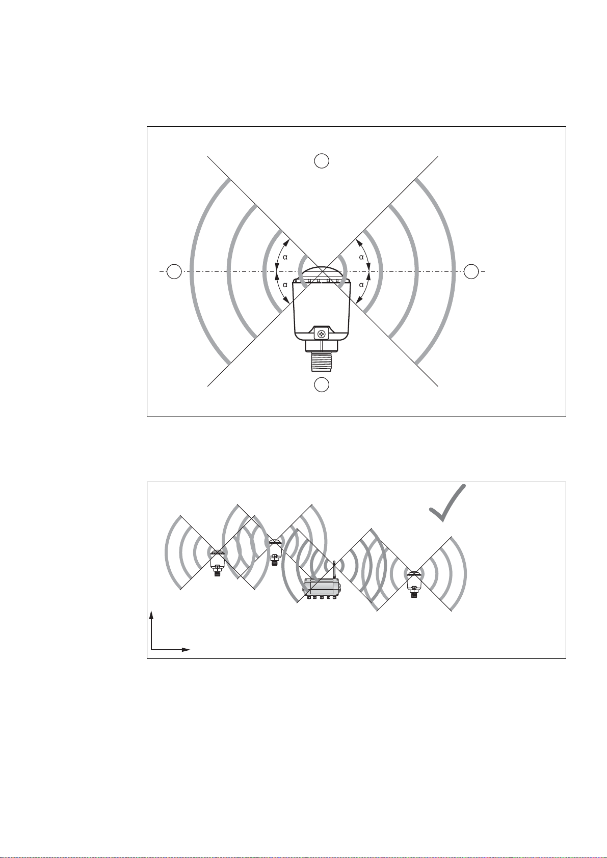
4.1.2 Examples for Good and Poor Positioning
1
2
2
1
x
y
BULLET
BULLET WirelessHART® Adapter
User's Manual, December 2017
700-701-96A
www.miinet.com
Moore Industries-International, Inc.
The adapter has an internal antenna which radiates out from the top cap in a 360° pattern.
Figure 4.1 Schematic representation of wave propagation
1. Weaker signal above and below the adapter
2. Stronger signal sideways
Figure 4.2 Good positioning: Devices are within each other's antenna range
2015-12
41
Page 46

Figure 4.3 Poor positioning: Devices are not within each other's antenna range
x
y
BULLET
BULLET WirelessHART® Adapter
User's Manual, December 2017
700-701-96A
www.miinet.com
Moore Industries-International, Inc.
4.1.3 Installation Options
The adapter can be mounted in three different ways:
1. Installation on Field Device
The adapter is attached to the field device using standard installation components that
meet the required type of protection and equipment protection level.
2. Separate from Field Device and Connected by Cable
The adapter can be placed anywhere on the current loop and does not need to be positioned directly next to the associated field device. The connection to the field device is
made using standard installation components that meet the required type of protection and
equipment protection level.
This installation method is recommended in the following situations:
• If there is insufficient space at the measuring point to mount the adapter directly to
the field device.
• If the signal reception at the measuring point is too weak for correct operation.
• If the measuring point is subject to vibration above the permissible limits.
3. Additional Stand-Alone Router
WirelessHART is a mesh network, which means that each node in the network will route
messages on behalf of other nodes in the network. This is done to expand the overall
range of the network and to form multiple redundant paths. By placing the adapter at key
locations in a WirelessHART network, this routing function can be offloaded from other devices, for example, to preserve battery life of battery powered nodes.
42
2015-12
Page 47

4.2 Explosion-Hazardous and Non-Explosion Hazardous Areas
BULLET
BULLET WirelessHART® Adapter
User's Manual, December 2017
700-701-96A
www.miinet.com
Moore Industries-International, Inc.
Different models are available that have been approved for different operating locations. The
nameplate on the housing clearly indicates the device marking for each model. Verify that the
selected model of the adapter is appropriate for the intended installation.
Model Number Operating Location
110100-x0M0
110102-x0M0
110101-x0M0
Not
e: x=P or 8
Danger!
Explosion hazard
Devices that have been operated in general industrial areas, lose all approvals for installations
in combination with hazardous areas.
■ If the device has been operated in non-explosion hazardous areas, the device must no
longer be used in combination with hazardous areas.
■ If circuits with type of protection Ex ic are operated with non-intrinsically safe circuits, they
must no longer be used as circuits with type of protection Ex ic.
Installation in general industrial areas
Installation in Zone 1, 21
Installation in Class I, Div. 1
Installation in Zone 0, 20
Installation in Zone 1, 21
Installation in Class I, Div. 1
4.3 Wiring
4.3.1 Field Wiring
Danger!
Explosion hazard
Unused cables and non-insulated metal parts may lead to ignition sparks that ignite a
potentially explosive atmosphere.
■ Install cables and connection lines in a way that they are protected from ultraviolet
radiation.
■ Install cables and connection lines in a way that they are not exposed to mechanical
hazards.
■ When installing the conductors the insulation must reach up to the terminal.
■ Ensure that unused terminal screws are properly tightened down.
■ When using stranded conductors, crimp wire end ferrules on the conductor ends.
■ Use the shortest possible cable lengths and avoid small core cross-sections.
■ Unused cables and connection lines must be connected to earth or be adequately
insulated by means of terminals suitable for the type of protection.
■ Insulation by tape alone is not permitted.
■ Keep the separation distances between all non-intrinsically safe circuits and intrinsically
safe circuits according to IEC/EN 60079-14.
2015-12
43
Page 48

Danger!
1
2
BULLET
BULLET WirelessHART® Adapter
User's Manual, December 2017
700-701-96A
www.miinet.com
Moore Industries-International, Inc.
Explosion hazard
Non-intrinsically safe circuits may lead to ignition sparks that ignite a potentially explosive
atmosphere.
Connect or disconnect non-intrinsically safe circuits only in the absence of a potentially
explosive atmosphere.
The following table describes the cables exiting the adapter.
Color Wire Gauge Description
Green / Yellow 14 AWG Internal Ground Connection
Black 20 AWG Direct Power
Red 20 AWG Loop Power
Yellow 20 AWG HART
White 20 AWG Return
Direct Power: The adapter is supplied by an external power supply, for example, a battery, or a
solar panel. The direct power connection is between the black conductor (Direct Power) and
the white conductor (Return).
Loop Power: The adapter is supplied by the 4 ... 20 mA current loop. The loop power
connection is between the red conductor (Loop Power) and the white conductor (Return).
HART: The HART connection is polarity independent. The HART connection is between the
yellow conductor (HART) and the white conductor (Return).
4.3.2 Grounding
The adapter provides an external and internal ground connection.
1. External Grounding Connection
2. Internal Grounding Connection
44
2015-12
Page 49

Danger!
1
2
3
4
2
BULLET
BULLET WirelessHART® Adapter
User's Manual, December 2017
700-701-96A
www.miinet.com
Moore Industries-International, Inc.
Explosion hazard
Unused cables and non-insulated metal parts pose an ignition hazard.
■ Install cables and connection lines in a way that they are protected from ultraviolet
radiation.
■ Install cables and connection lines in a way that they are not exposed to mechanical
hazards.
■ When installing the conductors the insulation must reach up to the terminal.
■ Ensure that unused terminal screws are properly tightened down.
■ When using stranded conductors, crimp wire end ferrules on the conductor ends.
■ Use the shortest possible cable lengths and avoid small core cross-sections.
■ Unused cables and connection lines must be connected to earth or be adequately
insulated by means of terminals suitable for the type of protection.
■ Insulation by tape alone is not permitted.
■ Keep the separation distances between all non-intrinsically safe circuits and intrinsically
safe circuits according to IEC/EN 60079-14.
Danger!
Explosion hazard
Non-intrinsically safe circuits may lead to ignition sparks that ignite a potentially explosive
atmosphere.
Connect or disconnect non-intrinsically safe circuits only in the absence of a potentially
explosive atmosphere.
Connecting the external ground connection
The external ground connection accepts wire gauges up to 10 AWG.
1. Connect the ground cable to a cable lug.
2. Position the cable lug over the grounding terminal so that the cable points downwards.
3. Screw the cable lug to the grounding terminal using two toothed lock washers.
4. Tighten the screw so that the cable lug cannot move.
2015-12
1. Stainless steel screw
2. Toothed lock washer
3. Cable lug
4. Grounding terminal
45
Page 50
Connecting the internal ground connection
BULLET
BULLET WirelessHART® Adapter
User's Manual, December 2017
700-701-96A
www.miinet.com
Moore Industries-International, Inc.
The internal ground connection is attached to the metal housing and exits the ½ inch NPT
thread as a 14 AWG conductor (green / yellow).
Connect the green / yellow conductor to the internal grounding terminal of the field device or
junction box that the adapter is attached to.
4.4 Installation on Field Device
The adapter is equipped with a male ½ inch NPT thread that allows direct connection to a field
device or junction box. In connection with other thread types, such as M20, you need a
connection adapter.
Note!
When loop powered, the adapter cannot control the current on the 4 ... 20 mA current loop.
Make sure that the current on the current loop is limited to within the operating specifications.
Danger!
Explosion hazard
Accessories and other installation components pose an ignition hazard if they do not meet the
required type of protection and equipment protection level.
For installations in explosion-hazardous areas, all materials related to the installation must be
approved by a recognized approval agency, notified body, or national certification body as
suitable for use in that classified area, for that specific type of protection, and temperature
class.
Danger!
Explosion hazard
Improper installations may lead to ignition sparks that ignite a potentially explosive atmosphere.
■ Installations in explosion-hazardous areas must comply with approval for use in that
classified area and the markings on the nameplate.
■ Use the device only within the specified ambient conditions.
■ Keep the separation distances between all non-intrinsically safe circuits and intrinsically
safe circuits according to IEC/EN 60079-14.
■ Only appropriately trained and qualified personnel may carry out mounting, installation,
commissioning, operation, maintenance, and dismounting of the device. The personnel
must have read and understood the instruction manual.
Danger!
Explosion hazard
Non-intrinsically safe circuits may lead to ignition sparks that ignite a potentially explosive
atmosphere.
Connect or disconnect non-intrinsically safe circuits only in the absence of a potentially
explosive atmosphere.
46
2015-12
Page 51

Danger!
BULLET
BULLET WirelessHART® Adapter
User's Manual, December 2017
700-701-96A
www.miinet.com
Moore Industries-International, Inc.
Explosion hazard
Unused cables and non-insulated metal parts may lead to ignition sparks that ignite a
potentially explosive atmosphere.
■ Install cables and connection lines in a way that they are protected from ultraviolet
radiation.
■ Install cables and connection lines in a way that they are not exposed to mechanical
hazards.
■ When installing the conductors the insulation must reach up to the terminal.
■ Ensure that unused terminal screws are properly tightened down.
■ When using stranded conductors, crimp wire end ferrules on the conductor ends.
■ Use the shortest possible cable lengths and avoid small core cross-sections.
■ Unused cables and connection lines must be connected to earth or be adequately
insulated by means of terminals suitable for the type of protection.
■ Insulation by tape alone is not permitted.
■ Keep the separation distances between all non-intrinsically safe circuits and intrinsically
safe circuits according to IEC/EN 60079-14.
Caution!
Damage due to wear
Aluminum galling can damage the device.
Apply an electrically conductive thread lubricant to the NPT threads to prevent the potential of
aluminum galling.
Caution!
Damage due to overcurrent
A current that exceeds the operating specifications of the device can cause damage to the
device.
Ensure that the supplied current never exceeds 32 V DC.
Mounting the adapter on a field device
1. Apply an electrically conductive thread lubricant to the NPT threads.
2. Apply gaskets where needed on either side of the pipe fittings.
3. Connect the adapter according to one of the following configuration diagrams.
4. Insert the adapter into a spare connection of the field device.
5. Use a spanner to fasten the adapter in place (torque 5 Nm + 1 Nm).
6. Connect the external ground connection in accordance with the grounding concept of your
application. See chapter 4.3.2
2015-12
47
Page 52
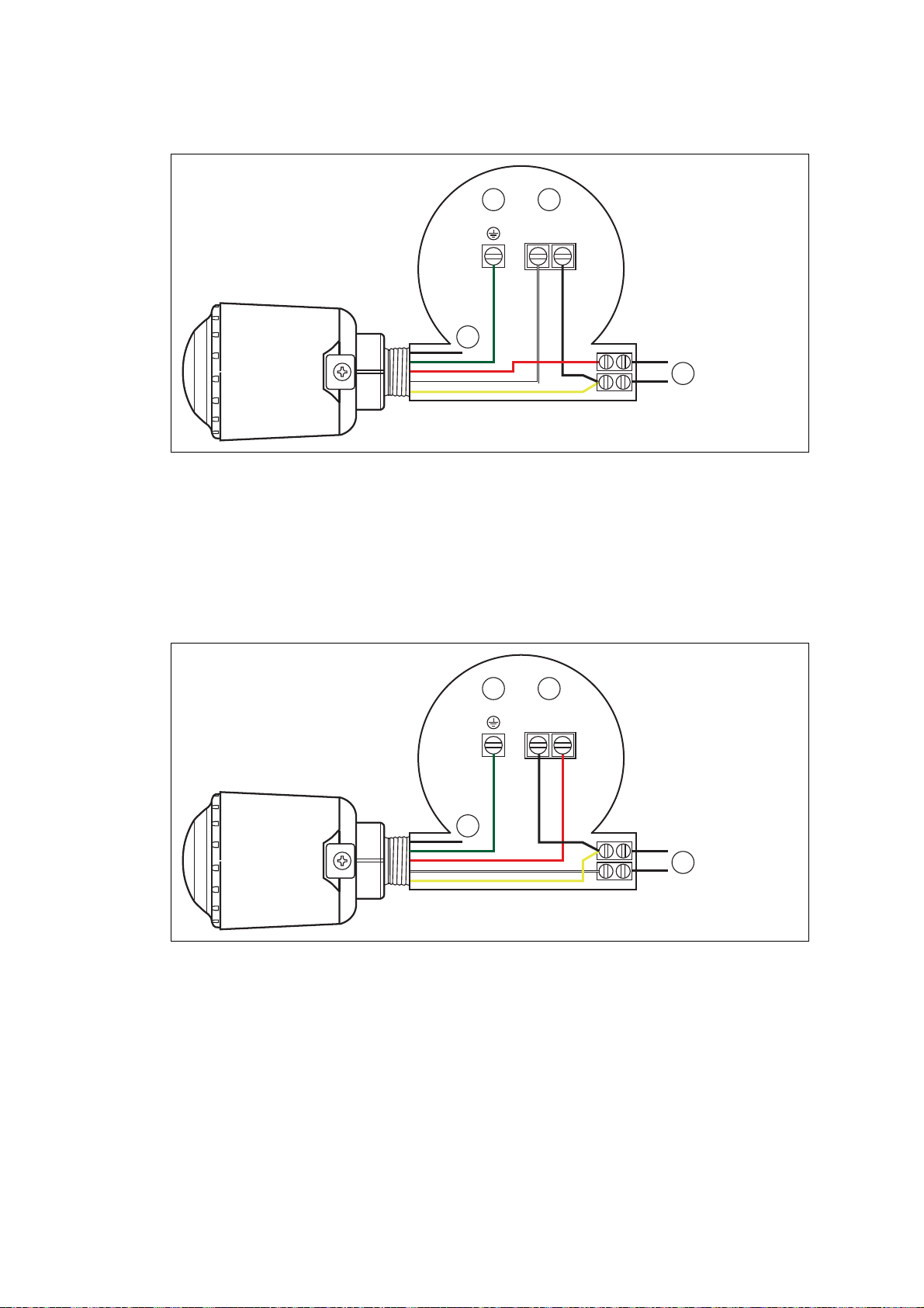
Loop Power: Configuration 1
+
-
L1+L2
-
1
2 3
4
+
-
L1+L2
-
1
2 3
4
BULLET
BULLET WirelessHART® Adapter
User's Manual, December 2017
700-701-96A
www.miinet.com
Moore Industries-International, Inc.
Figure 4.4 Loop powered adapter connected to the positive terminal (+) of the current loop and the
positive terminal (+) of the field device's current loop connection.
1. Insulated black conductor (Direct Power)
2. Ground connection of the field device
3. Current loop connection of the field device
4. Current loop
Loop Power: Configuration 2
Figure 4.5 Loop powered adapter connected to the negative terminal (-) of the current loop and the
negative terminal (-) of the field device's current loop connection.
1. Insulated black conductor (Direct Power)
2. Ground connection of the field device
3. Current loop connection of the field device
4. Current loop
48
2015-12
Page 53

Direct Power
+
-
L1+L2
-
1
2 3
4
mA
BULLET
BULLET WirelessHART® Adapter
User's Manual, December 2017
700-701-96A
www.miinet.com
Moore Industries-International, Inc.
Figure 4.6 Directly powered adapter connected to the positive terminal (+) of the power supply and
the negative terminal (-) of the power supply.
1. Insulated red conductor (Loop Power)
2. Ground connection of the field device
3. Current loop connection of the field device
4. External DC power supply (7 ... 32 V DC)
4.5 Installation as Stand-Alone Router
By placing the adapter at key locations in a WirelessHART network, you can improve the
overall network robustness and offloaded packet routing from other devices, for example, to
preserve battery life of battery powered devices. The adapter can be placed anywhere on the
current loop, or it can be used as stand-alone router that is powered by an external power
supply.
Danger!
Explosion hazard
Accessories and other installation components pose an ignition hazard if they do not meet the
required type of protection and equipment protection level.
For installations in explosion-hazardous areas, all materials related to the installation must be
approved by a recognized approval agency, notified body, or national certification body as
suitable for use in that classified area, for that specific type of protection, and temperature
class.
2015-12
49
Page 54

Danger!
BULLET
BULLET WirelessHART® Adapter
User's Manual, December 2017
700-701-96A
www.miinet.com
Moore Industries-International, Inc.
Explosion hazard
Improper installations may lead to ignition sparks that ignite a potentially explosive atmosphere.
■ Installations in explosion-hazardous areas must comply with approval for use in that
classified area and the markings on the nameplate.
■ Use the device only within the specified ambient conditions.
■ Keep the separation distances between all non-intrinsically safe circuits and intrinsically
safe circuits according to IEC/EN 60079-14.
■ Only appropriately trained and qualified personnel may carry out mounting, installation,
commissioning, operation, maintenance, and dismounting of the device. The personnel
must have read and understood the instruction manual.
Danger!
Explosion hazard
Non-intrinsically safe circuits may lead to ignition sparks that ignite a potentially explosive
atmosphere.
Connect or disconnect non-intrinsically safe circuits only in the absence of a potentially
explosive atmosphere.
Danger!
Explosion hazard
Unused cables and non-insulated metal parts may lead to ignition sparks that ignite a
potentially explosive atmosphere.
■ Install cables and connection lines in a way that they are protected from ultraviolet
radiation.
■ Install cables and connection lines in a way that they are not exposed to mechanical
hazards.
■ When installing the conductors the insulation must reach up to the terminal.
■ Ensure that unused terminal screws are properly tightened down.
■ When using stranded conductors, crimp wire end ferrules on the conductor ends.
■ Use the shortest possible cable lengths and avoid small core cross-sections.
■ Unused cables and connection lines must be connected to earth or be adequately
insulated by means of terminals suitable for the type of protection.
■ Insulation by tape alone is not permitted.
■ Keep the separation distances between all non-intrinsically safe circuits and intrinsically
safe circuits according to IEC/EN 60079-14.
Caution!
Damage due to wear
Aluminum galling can damage the device.
Apply an electrically conductive thread lubricant to the NPT threads to prevent the potential of
aluminum galling.
50
2015-12
Page 55

Caution!
+
-
1
3
mA
2
4
BULLET
BULLET WirelessHART® Adapter
User's Manual, December 2017
700-701-96A
www.miinet.com
Moore Industries-International, Inc.
Damage due to overcurrent
A current that exceeds the operating specifications of the device can cause damage to the
device.
Ensure that the supplied current never exceeds 32 V DC.
Mounting the adapter on a junction box
1. Apply an electrically conductive thread lubricant to the NPT threads.
2. Connect the adapter according to the following configuration diagram.
3. Insert the adapter into a spare connection of the junction box.
4. Use a wrench to fasten the adapter in place (torque 5 Nm + 1 Nm).
5. Connect the external ground connection in accordance with the grounding concept of your
application. See chapter 4.3.2
Stand-Alone Router
Figure 4.7 Directly powered adapter connected to the positive terminal (+) of the power supply and
the negative terminal (-) of the power supply.
1. Insulated red conductor (Loop Power)
2. Ground connection of the junction box
3. External DC power supply (7 ... 32 V DC)
4. To HART terminator
2015-12
51
Page 56

5
BULLET
BULLET WirelessHART® Adapter
User's Manual, March 2017
700-701-96A
www.miinet.com
Moore Industries-International, Inc.
5.1
HART Variables
The adapter appears as a HART device on both the wired HART network and the
WirelessHART network and supports 4 HART variables. The variables can be read using
standard HART commands.
HART Variable Expression
Primary variable (PV) Loop Current (mA)
Secondary variable (SV) Direct Power Voltage (V)
Ter ti ar y va r i a b l e ( TV ) Internal Temperature (°C)
Quaternary variable (QV) Storage Voltage (V) (internal to the adapter)
Operation
2015-12
52
Page 57

6Troubleshooting
BULLET
BULLET WirelessHART® Adapter
User's Manual, December 2017
700-701-96A
www.miinet.com
Moore Industries-International, Inc.
Wireless Communication Faults
Fault Possible Cause(s) Corrective Action(s)
PACTware cannot
find the adapter
when
communicating
over the
WirelessHART
gateway.
The adapter does
not join the
network.
The adapter has not yet joined the
network.
The adapter carries the wrong
network ID or join key.
The adapter carries the wrong
network ID or join key.
The adapter resets itself due to
insufficient power supply.
There are no neighboring
WirelessHART devices within the
adapter's antenna range.
The joining process may take a
while. Check the join status in the
gateway's instrument list.
Alternatively, check the join status of
the adapter using a HART modem
connected to the adapter.
Check the wireless communication
parameters of the adapter using a
HART modem connected to the
adapter. The adapter and the
gateway must have the same
network ID and join key.
Check the wireless communication
parameters of the adapter using a
HART modem connected to the
adapter. The adapter and the
gateway must have the same
network ID and join key.
Check the power settings of the
adapter. See chapter 3.2.5
Check whether the adapter is placed
at the right location.
■ Add another adapter to the
WirelessHART network, for
example, as stand-alone router.
■ Change
the mounting position of
the adapter, as the adapter can
be placed anywhere on the
current loop.
2015-12
Adapter
disappears
sporadically from
the
WirelessHART
network.
There are not enough neighboring
WirelessHART devices within the
adapter's antenna range.
Check whether the adapter is placed
at the right location.
■ Add another adapter to the
WirelessHART network, for
example, as stand-alone router.
■ Change
the mounting position of
the adapter, as the adapter can
be placed anywhere on the
current loop.
Page 58

Wired Communication Faults
BULLET
BULLET WirelessHART® Adapter
User's Manual, December 2017
700-701-96A
www.miinet.com
Moore Industries-International, Inc.
Fault Possible Cause(s) Corrective Action(s)
PACTware cannot
find the adapter
when
communicating
over a HART
modem.
The HART communication DTM is
not connected to the right COM port.
Some PCs assign fixed COM ports
to USB ports. The HART modem is
plugged into a different USB port
than during setup.
Change the COM port in the HART
communication DTM. See chapter
3.2.1
■ Plug the HART modem into the
USB port used during setup.
■ Change the COM port in the
HART communication DTM. See
chapter 3.2.1
The adapter's polling address
cannot be found by the HART
Use polling address 15 in the
adapter DTM. See chapter 3.2.2
communication DTM.
Adapter does not
detect a
connected field
The adapter is not properly wired to
the field device.
Check whether the wiring is correct
for the selected type of supply (loop
power or direct power) see chapter 4
device.
A field device
powered by the
adapter does not
start up.
The voltage of the external power
supply has dropped below the Field
Device Cutoff Voltage.
The Field Device Power Control
option is enabled and the Field
Device Turn On Time or Field
Device Idle Time are not configured
properly.
Check the battery status and if
required, replace the battery see
chapter 3.2.13
■ Check whether the Field Device
Tu r n O n T i m e is sufficiently
long, in order to obtain accurate
measurements from the field
devices.
■ Check whether the Field Device
Idle Time is sufficiently long, in
order to prevent the adapter from
switching off the field device
when another master
communicates with the field
device.
See chapter 3.2.5
Adapter does not
restart after
disconnecting
The power supply was reconnected
before the adapter was fully
discharged.
Wait approximately 1 minute before
reconnecting the power supply.
and reconnecting
the power supply.
2015-12
Page 59

7 Control Drawings & Certifications
Bullet – Wireless HART Adapter
Documentation
No revision to
For installations in the US, the associated apparatus and field device must be FM approved.
For installations in Canada, the associated apparatus and field device must be Canadian certified.
For Zone installations, the associated apparatus and field device must be ATEX / IEC certified.
For installations in EU, control room equipment connected to intrinsically safe associated apparatus shall not use or
generate more than the marked Um of the associated apparatus.
Resistance between intrinsically safe ground and earth ground must be less than 1.0 Ohm.
Due to constant revisions, documentation is subject to permanent change. Please refer only to the most up-to-date
version, which can be found under www.pepperl-fuchs.com.
Responsibility for planning, assembly, commissioning, operation, maintenance, and dismounting lies with the plant
operator.
Only appropriately trained and qualified personnel may carry out mounting, installation, commissioning, operation,
maintenance, and dismounting of the device. The personnel must have read and understood the instructio n manual.
The device is only approved for appropriate and intended use. Ignoring these instructions will void any warranty and
absolve the manufacturer from any liability.
Protection of the personnel and the plant is not ensured if the device is not being used according to its intended use.
drawing without prior FM approval.
General
Make sure to con
NEC, CEC, IEC 60079-14 and/or IEC 60079-25.
The usage of 2400 MHz equipment is bound to local restrictions. Ensu re that local restrictions allow usage of this device
before commissioning.
sider all applicable laws, standards or directives especially national standards and guidelines such as
The device must not be repaired, changed or manipulated.
If there is a defect, always replace the device with an original device from Pepperl+Fuchs.
The device is used in control and instrumentation technology (C&I technology) for wireless data transfer from HART
devices.
Take the intended use of the connected devices from the corresponding documentation.
Use the device only within the specified ambient temperature range.
Do not mount the device at locations where an aggressive atmosphere may be present.
Do not mount a damaged or polluted device.
Avoid electrostatic charges which could result in electrostatic discharges while installing or operating the d evice.
Provide a transient protection. Ensure that the peak value of the transient protection does not exceed 140 % of the
rated voltage.
When the device is in operation, maintain at all times a distance of at least 20 cm to the device antenna. This also
applies to any other person in the vicinity of the device.
Install cables and cable glands in a way that they are not exposed to mechanical hazards.
Protect cables and cable glands from tensile load and torsional stress, or use certified cable glands.
Dieses Dokument enthält sicherheitsrelevante Angaben. Es darf nicht ohne Absprache mit dem Normenexperten (NE Ex) geändert werden!
This document contains safety-relevant information. It must not be altered without the authorization of the norm expert (NE Ex)!
CONFIDENTIAL acc. to ISO 16016 Only valid as longs as released in EDM! 2017-Jun-22
Worldwide
Control Drawing
WHA-BLT-F9D0-N-A0-**-*1
116-0425
sheet
1 of 8
Page 60

Unused cables and connection lines must be either connected to terminals or securely tied down and isolated.
If cable glands are needed for installation, the following points must be considered:
The cable glands used must be suitably certified fo r the application
The temperature range of the cable glands must be chosen according to the application.
The cable glands fitted must not reduce the degree of protection.
If the device has already been operated in general electrical installations, the device may subsequently no longer be
installed in electrical installations used in combination with hazardous areas.
All separation distances between non-intrinsically safe circuits and intrinsically safe circuits need to be observed.
All separation distances between adjacent intrinsically safe ci rcuits need to be observed.
Intrinsically safe circuits must be wired and separated in accordance with Article 504.20 of the National Electrical Code
(ANSI/NFPA 70) for USA and Section 12 and Appendix F of the Canadian Electrical Code (CEC Part I, C22.1-12 or
later) for Canada, and other local codes, as applicable.
Connection or disconnection of energized non-intrinsically safe circuits is only permitted in the absence of a potentially
explosive atmosphere.
If circuits with type of protection Ex i are operated with non-intrinsically safe circuits, they must no longer be used as
circuits with type of protection Ex i.
The entity concept allows interconnection of intrinsically safe apparatus with associated apparatus not specifically
examined in combination as a system when the approved values of Uo (Voc) and Io (Isc) for the associated apparatus are
less than or equal to Ui (V
) and Ii (I
max
) for the intrinsically safe apparatus.
max
Capacitance and inductance of the field wiring between intrinsically safe equipment and the associated a pparatus shall
be calculated and must be included in the system calculations. Cable capacitan ce C
capacitance C
applies for the values for inductance (L
per foot are not known, the following values shall be used: C
must be less than the capacitance Co (Ca), marked on any connected associated apparatus. The same
i
, Li and Lo or La, respectively). Where the cable capacitance and inductance
cable
= 60 pF/ft., L
cable
cable
plus intrinsically safe equipment
cable
= 0.2 µH/ft.
Where multiple circuits extend from the same piece of associated apparatus, they must be installed in separate cables
or in one cable having suitable insulation. Refer to Article 504.30(B) of the National Electrical Code (ANSI/NFPA 70)
and Instrument Society of America Recommended Practice ISA RP12.6 for installing intrinsically safe equipment in
USA and refer to Section 12 and Appendix F of the National Electrical Code (CEC Part I, C22.1-12 or later) for installing
intrinsically safe equipment in Canada.
Delivery, Transport, Disposal
Check the packaging and contents for damage.
Check if you have received every item and if the items received are the ones you ordered.
Keep the original packaging. Always store and transport the device in the original packaging.
Store the device in a clean and dry environment. The permitted ambient conditions (see datasheet) must be con
sidered.
Disposing of device, packaging, and possibly contained batteries must be in compliance with the applicable laws and
guidelines of the respective country.
Dieses Dokument enthält sicherheitsrelevante Angaben. Es darf nicht ohne Absprache mit dem Normenexperten (NE Ex) geändert werden!
This document contains safety-relevant information. It must not be altered without the authorization of the norm expert (NE Ex)!
CONFIDENTIAL acc. to ISO 16016 Only valid as longs as released in EDM! 2017-Jun-22
Worldwide
Control Drawing
WHA-BLT-F9D0-N-A0-**-*1
116-0425
sheet
2 of 8
Page 61

WHA-BLT-F9D0-N-A0-Z0-Ex1
,
,
3 3
556
(Bullet – intrinsically safe Wireless HART Adapter)
AREA CLASSIFICATIONS
NON-HAZARDOUS LOCATION
or
HAZARDOUS LOCATION
CLASS I, DIVISION 1, GROUPS A, B, C, D
CLASS II, DIVISION 1, GROUPS E, F, G
CLASS III, DIVISION 1
or
CLASS I, DIVISION 2, GROUPS A, B; C; D
or
CLASS I
ZONE 0, 1 and 2, GROUP IIC
4
WHA-BLT-F9D0-N-A0-Z1-1
(Bullet – explosion proof Wireless HART Adapter)
NON-HAZARDOUS LOCATION
or
HAZARDOUS LOCATION
7
AREA CLASSIFICATIONS
NON-HAZARDOUS LOCATION
or
HAZARDOUS LOCATION
CLASS I, DIVISION 1, GROUPS A, B, C, D
CLASS II, DIVISION 1, GROUPS E, F, G
CLASS III, DIVISION 1
or
CLASS I, DIVISION 2, GROUPS A, B; C; D
or
CLASS I
ZONE 1 and 2, GROUP IIC
4
NON-HAZARDOUS LOCATION
or
HAZARDOUS LOCATION
CLASS I, DIVISION 1 or Zone 1 or
CLASS I, DIVISION 2 or Zone 2
7
Dieses Dokument enthält sicherheitsrelevante Angaben. Es darf nicht ohne Absprache mit dem Normenexperten (NE Ex) geändert werden!
This document contains safety-relevant information. It must not be altered without the authorization of the norm expert (NE Ex)!
CONFIDENTIAL acc. to ISO 16016 Only valid as longs as released in EDM! 2017-Jun-22
Control Drawing
Worldwide
WHA-BLT-F9D0-N-A0-**-*1
116-0425
sheet
3 of 8
Page 62

345
WHA-BLT-F9D0-N-A0-GP-1
(Bullet – general purpose Wireless HART Adapter)
AREA CLASSIFICATIONS
HAZARDOUS LOCATION
NON-HAZARDOUS LOCATION
7
Dieses Dokument enthält sicherheitsrelevante Angaben. Es darf nicht ohne Absprache mit dem Normenexperten (NE Ex) geändert werden!
This document contains safety-relevant information. It must not be altered without the authorization of the norm expert (NE Ex)!
CONFIDENTIAL acc. to ISO 16016 Only valid as longs as released in EDM! 2017-Jun-22
Worldwide
Control Drawing
WHA-BLT-F9D0-N-A0-**-*1
116-0425
sheet
4 of 8
Page 63

888
8
8 8
LOOP POWER #1
Interconnections
2
LOOP POWER #2
LOOP POWER #3 – ACTIVE DEVICE
+
-
1
2
+
-
1
2
Dieses Dokument enthält sicherheitsrelevante Angaben. Es darf nicht ohne Absprache mit dem Normenexperten (NE Ex) geändert werden!
This document contains safety-relevant information. It must not be altered without the authorization of the norm expert (NE Ex)!
CONFIDENTIAL acc. to ISO 16016 Only valid as longs as released in EDM! 2017-Jun-22
Worldwide
Control Drawing
WHA-BLT-F9D0-N-A0-**-*1
116-0425
sheet
5 of 8
Page 64

888
8
DIRECT POWER #1 – FIELD DEVICE CONTROL
2
+
1
-
DIRECT POWER #2 - REPREATER
2
+
-
1
All interconnections allow multi-drop (several field devices), see data sheet and manual for more information.
Dieses Dokument enthält sicherheitsrelevante Angaben. Es darf nicht ohne Absprache mit dem Normenexperten (NE Ex) geändert werden!
This document contains safety-relevant information. It must not be altered without the authorization of the norm expert (NE Ex)!
CONFIDENTIAL acc. to ISO 16016 Only valid as longs as released in EDM! 2017-Jun-22
Worldwide
Control Drawing
WHA-BLT-F9D0-N-A0-**-*1
116-0425
sheet
6 of 8
Page 65

Special conditions of safe use
5
6
8 3
1
The associat
Provide a transient protection. Ensure that the peak value of the transient protection does not exceed 140 % of the
2
rated voltage.
Using the tick box provided on the nameplate, the user shall permanently mark the type of protection chosen for the
specific installation. Once the type of protection has been marked it shall not be changed.
The equipment contains aluminum and is considered to constitute a potential risk of ignition by impact or friction. Care
4
must be taken into account during installation and use to prevent impact and friction.
ed apparatus must provide resistively limited characterist ics.
Dust-tight conduit seals must be used to ensure the degree of protection.
The flying leads of the apparatus shall be suitably protected against mechanical damage and terminated within an
NRTL Approved, Listed or Recognized terminal or junction facility suitable for the location and conditions of use.
Unused cables and connection lines must be either connected to terminals or securely tied down and isolated.
The Class I, Zone 1 AEx d IIC configuration requires the use of an NRTL Approved, Listed or Recognized cable seal,
suitable for the location and conditions of use, installed at the apparatus and prior to the terminal or junction facility.
The ambient temperature range is - 40 °C < Ta < + 85 °C for temperature class T5 and ordinary location and - 40 °C <
7
Ta < + 75 °C for temperature class T6.
The device provides a grounding terminal to which an equipotential bonding conductor with a minimum cross section of
4 mm² must be connected. The tightening torque for all screws is 1.1 Nm.
WARNING – Explosion Hazard – Do not disconnect equipment unless power has been switched off or the area is
known to be nonhazardous.
AVERTISSEMENT – RISQUE D'EXPLOSION - Ne pas déconnecter l'appareil si sous tension ou en présence d'une
atmosphère explosive.
Dieses Dokument enthält sicherheitsrelevante Angaben. Es darf nicht ohne Absprache mit dem Normenexperten (NE Ex) geändert werden!
This document contains safety-relevant information. It must not be altered without the authorization of the norm expert (NE Ex)!
CONFIDENTIAL acc. to ISO 16016 Only valid as longs as released in EDM! 2017-Jun-22
Control Drawing
Worldwide
WHA-BLT-F9D0-N-A0-**-*1
116-0425
sheet
7 of 8
Page 66

Table 1 – ELECTRICAL PARAMETERS
ENTITY PARAMETERS
MODEL
TYPE
WHA-BLT-F9D0-N-A0-Z0-Ex1 See INTERCONNECTIONS above See Ui See Ii 30 120 900 negligible 596
WHA-BLT-F9D0-N-A0-Z1-1 See INTERCONNECTIONS above 7 – 32 < 25 n.a. n.a. n.a. n.a. n.a.
WHA-BLT-F9D0-N-A0-GP-1 See INTERCONNECTIONS above 7 - 32 < 25 n.a. n.a. n.a. n.a. n.a.
FIELD
CONNECTIONS
U
ext_power
[V]
I
ext_power
[mA]
Ui (V
)
Ii (I
)
[V]
max
[mA]
max
Pi (P
[mW]
max
Important for the determination (verification) of intrinsic safety:
The values of L
- The total L
- The total C
and Co of the associated apparatus are allowed if one of the following conditions is met:
o
of the external circuit (excluding the cable) is < 1% of the Lo (La) value or
i
of the external circuit (excluding the cable) is < 1% of the Co (Ca) value.
i
The values of L
- the total L
and Co of the associated apparatus shall be reduced to 50% when both of the following conditions are met:
o
of the external circuit (excluding the cable) is > 1% of the Lo (La) value and
i
- the total Ci of the external circuit (excluding the cable) is > 1% of the Co (Ca) value.
Note: the reduced capacitance of the external circuit (including cable) shall not be greater than 1µF for IIA and IIB and 600nF for IIC.
When C
(Ca) of the associated apparatus is > 22 µF, then total cable capacitance shall be li mited to 22 µF.
o
)
Ci
[nF]
Li
[µH]
Dieses Dokument enthält sicherheitsrelevante Angaben. Es darf nicht ohne Absprache mit dem Normenexperten (NE Ex) geändert werden!
This document contains safety-relevant information. It must not be altered without the authorization of the norm expert (NE Ex)!
CONFIDENTIAL acc. to ISO 16016 Only valid as longs as released in EDM! 2016-Jun-22
Worldwide
Control Drawing
WHA-BLT-F9D0-N-A0-**-*1
116-0425
sheet
8 of 8
Page 67

1
EU-TYPE EXAMINATION CERTIFICATE
2 Equipment or Protective systems intended for use in Potentially
Explosive Atmospheres - Directive 2014/34/EU
3 EU-Type Examination Certificate No: FM17ATEX0046X
4 Equipment or protective system:
(Type Reference and Name)
5 Name of Applicant: Pepperl+Fuchs GmbH
6 Address of Applicant: Lilienthalstrasse 200
7 This equipment or protective system and any acceptable variation thereto is specified in the schedule to this
certificate and documents therein referred to.
8 FM Approvals Ltd, notified body number 1725 in accordance with Article 17 of Directive 2014/34/EU of
26 February 2014, certifies that this equipment has been found to comply with the Essential Health and
Safety Requirements relating to the design and construction of equipment intended for use in potentially
explosive atmospheres given in Annex II to the Directive.
The examination and test results are recorded in confidential report number:
3062160 dated 11
WHA-BLT Series BULLET® WirelessHART® Adapter
D-68307 Mannheim
German
y
th
August 2017
9 Compliance with the Essential Health and Safety Requirements, with the exception of those identified in item
15 of the schedule to this certificate, has been assessed by compliance with the following documents:
EN 60079-0:2012+A11:2013, EN 60079-1:2014, EN 60079-11:2012 and EN 60079-31:2014
10 If the sign ‘X’ is placed after the certificate number, it indicates that the equipment is subject to specific
conditions of use specified in the schedule to this certificate.
11 This EU-Type Examination certificate relates only to the design, examination and tests of the specified
equipment or protective system in accordance to the directive 2014/34/EU. Further requirements of the
Directive apply to the manufacturing process and supply of this equipment or protective system. These are
not covered by this certificate.
12 The marking of the equipment or protective system shall include:
WHA-BLT-F9D0-N-A0-Z0-Ex1. BULLET® WirelessHART® Adaptor.
II 1 G Ex ia IIC T6…T5 Ga
T5 for Ta = -40°C to +85°C; T6 for Ta = -40°C to +75°C
II 1 D Ex ia IIIC T95°C Ta = -40°C to +85°C Da
Digitally signed by Nicholas Ludlam
DN: cn=Nicholas Ludlam, o=FM
Approvals, ou,
email=nicholas.ludlam@fmapprova
ls.com, c=GB
Date: 2017.08.16 11:30:44 +01'00'
Nicholas Ludlam
Deputy Certification Manager, FM Approvals Ltd.
th
Issue date: 16
THIS CERTIFICATE MAY ONLY BE REPRODUCED IN ITS ENTIRETY AND WITHOUT CHANGE
Approvals Ltd. 1 Windsor Dials, Windsor, Berkshire, UK. SL4 1RS
FM
T: +44 (0) 1753 750 000 F: +44 (0) 1753 868 700 E-mail: atex@fmapprov als.com www.fmapprovals.com
F ATEX 020 (Apr/16) Page 1 of 3
August 2017
Page 68

g
d
SCHEDULE
to EU-Type Examination Certificate No. FM17ATEX0046X
12 The marking of the equipment or protective system shall include (continued):
13
The Model WHA-BLT-F9D0 Series BULLET® WirelessHART® Adaptor is intended to be installed into a 4-
14 Specific Conditions of Use:
WHA-BLT-F9D0-N-A0-Z1-1. BULLET® WirelessHART® Adaptor.
II 2 G Ex db IIC T6…T5 Gb
T5 Ta = -40°C to +85°C ; T6 Ta = -40°C to +75°C
II 2 D Ex tb IIIC T95°C Ta = -40°C to +85°C Db
Description of Equipment or Protective System:
20 mA current loop with electrical equipment using HART communications. The HART electrical signals are
converted and delivered as wireless transmission. The electronics, except for the antenna board, are
completely encapsulated and located inside of a painted metallic cylindrical housing with a polymeric dome
cover. The antenna board protrudes through the encapsulation and is located under the polymeric dome
cover. The bottom side of the housing is sealed with potting material where pig-tail wires protrude through
the potting for installation. The housing also contains threads for installing into a cable gland or terminal /
junction facility.
Operation Temperature Ranges:
The ambient operating temperature range of the BULLET® WirelessHART® Adaptor is -40°C to 85°C. A
lower ambient temperature range of -40°C to +75°C is specified for Temperature Class T6
Electrical data:
The BULLET® WirelessHART® Adaptor has the following electrical ratings;
In type of protection intrinsic safety, Energy limitation parameters:
Ui = 30V, Ii = 120mA, Pi = 0.9W, Ci = 0, Li = 595.96ȝH.
All other protection techniques, the electronic connection has the following values:
7-32 V and 4-25 mA
WHA-BLT-F9D0-N-A0-Z0-Ex1. BULLET® WirelessHART® Adaptor.
WHA-BLT-F9D0-N-A0-Z1-1. BULLET® WirelessHART® Adaptor.
For WHA-BLT-F9D0-N-A0-Z0-Ex1. BULLET® WirelessHART® Adaptor.
1. For Zone 0 installation only, the equipment contains aluminum and is considered to constitute a potential
risk of ignition by impact or friction. Care must be taken into account during installation and use to prevent
impact and friction.
For WHA-BLT-F9D0-N-A0-Z1-1. BULLET® WirelessHART® Adaptor.
1. The flying leads of the apparatus shall be suitably protected against mechanical damage and terminated
within a suitable ATEX Certified Ex d or Ex e terminal or junction facility.
2. The Ex db IIC confi
conditions of use, installed at the apparatus and prior to the terminal or junction facility.
15 Essential Health and Safety Requirements:
The relevant EHSRs that have not been addressed by the standards listed in this certificate have been
identified and assessed in the confidential report identified in item 8.
THIS CERTIFICATE MAY ONLY BE REPRODUCED IN ITS ENTIRETY AND WITHOUT CHANGE
FM Approv als Ltd. 1 Windsor Dials, Windsor, Berkshire, UK. SL4 1RS
T: +44 (0) 1753 750 000 F: +44 (0) 1753 868 700 E-mail: atex@fmapprov als.com www.fmapprovals.com
F ATEX 020 (Apr/16) Page 2 of 3
uration requires the use of an ATEX Certified cable seal, suitable for the location an
Page 69

SCHEDULE
to EU-Type Examination Certificate No. FM17ATEX0046X
16 Test and Assessment Procedure and Conditions:
This EU-Type Examination Certificate is the result of testing of a sample of the product submitted, in
accordance with the provisions of the relevant specific standard(s), and assessment of supporting
documentation. It does not imply an assessment of the whole production.
Whilst this certificate may be used in support of a manufacturer’s claim for CE Marking, FM Approvals Ltd
accepts no responsibility for the compliance of the equipment against all applicable Directives in all
applications.
This Certificate has been issued in accordance with FM Approvals Ltd’s ATEX Certification Scheme.
17 Schedule Drawings
A list of the significant parts of the technical documentation is annexed to this certificate and a copy has
been kept by the Notified Body.
18 Certificate History
Details of the supplements to this certificate are described below:
Date Description
16th August 2017 Original Issue.
THIS CERTIFICATE MAY ONLY BE REPRODUCED IN ITS ENTIRETY AND WITHOUT CHANGE
FM Approv als Ltd. 1 Windsor Dials, Windsor, Berkshire, UK. SL4 1RS
T: +44 (0) 1753 750 000 F: +44 (0) 1753 868 700 E-mail: atex@fmapprov als.com www.fmapprovals.com
F ATEX 020 (Apr/16) Page 3 of 3
Page 70

CERTIFICATE OF CONFORMITY
1.
H
AZARDOUS LOCATION ELECTRICAL EQUIPMENT PER CANADIAN REQUIREMENTS
2.
Certificate No: FM17CA0102X
3.
Equipment:
(Type Reference and Name)
4.
Name of Listing Company:
5.
Address of Listing Company:
6. The examination and test results are recorded in conf
3062160 dated 11th August 2017
7. FM Approvals LLC, certifies that the equipment described has been found to comply with the following Approval
standards and other documents:
CSA-C22.2 No. 0.4:2017, CSA-C22.2 No. 0.5:2016, CSA-C22.2 No. 25:R2014,
CSA-C22.2 No. 30:R2016, CSA-C22.2 No. 94:R2011, CSA-C22.2 No. 157:R2016,
CAN/CSA-C22.2 No. 60079-0:2015, CAN/CSA-C22.2 No. 60079-1:2016,
CAN/CSA-C22.2 No. 60079-11:2014, CAN/CSA-C22.2 No. 60079-31:2015,
CSA-C22.2 No. 60529:2016, and CAN/CSA-C22.2 No. 61010-1:R2017
8. If the sign ‘X’ is placed after the certificate numbe
conditions of use specified in the schedule to this certificate.
9. This certificate relates to the design, examination and testing of the products specified herein. The FM
Approvals surveillance audit program has further determined that the manufacturing processes and quality
control procedures in place are satisfactory to manufacture the product as examined, tested and Approved.
WHA-BLT Series BULLET® WirelessHART® Adapter
Pepperl+Fuchs GmbH
Lilienthalstrasse 200
D-68307 Mannheim
Germany
idential report number:
r, it indicates that the equipment is subject to specific
10. Equipment Ratings:
In
trinsically Safe (Entity) for use in Class I, II, and III, Division 1, Groups A, B, C, D, E, F, and G T6 (-40˚C ≤ Ta
≤ 75˚C) and T5 (-40˚C ≤ Ta ≤ 85˚C); in accordance with Control Drawing No. 116-0425; Intrinsically Safe
(Entity) for use in Zone 0, Ex ia IIC Temperature Class T6 (-40˚C ≤ Ta ≤ 75˚C) and T5 (-40˚C ≤ Ta ≤ 85˚C); in
Certificate issued by:
11 August 2017
J. E. Marquedant
V
P, Manager, Electrical Systems
To verify the availability of the Approved product, please refer to www.approvalguide.com
THIS CERTIFICATE MAY ONLY BE REPRODUCED IN ITS ENTIRETY AND WITHOUT CHANGE
FM Approvals LLC. 1151 Boston-Providence Turnpike, Norwood, MA 02062 USA
T: +1 (1) 781 762 4300 F: +1 (1) 781 762 9375 E-mail: information@fmapprovals.com www.fmapprovals.com
F 348 (Mar 16) Page 1 of 3
Date
Page 71

SCHEDULE
Canadian Certificate Of Conformity No: FM17CA0102X
accordance with Control Drawing No. 116-0425; Intrinsically Safe (Entity) for use in Zone 20, Ex ia IIIC T95°C (40˚C ≤ Ta ≤ 85˚C) in accordance with Control Drawing No. 116-0425. Explosionproof for Class I, Division 1,
Groups A, B, C and D T6 (-40˚C ≤ Ta ≤ 75˚C) and T5 (-40˚C ≤ Ta ≤ 85˚C); Flameproof for Class I, Zone 1, Ex
db IIC T6 (-40˚C ≤ Ta ≤ 75˚C) and T5 (-40˚C ≤ Ta ≤ 85˚C); Dust-ignitionproof for Class II, III, Division 1, Groups
E, F, & G T6 (-40˚C ≤ Ta ≤ 75˚C) and T5 (-40˚C ≤ Ta ≤ 85˚C); and Zone 21, Ex tb IIIC T95°C (-40˚C ≤ Ta ≤
85˚C) indoors and outdoors Type 6P and IP67 hazardous locations.
11. The marking of the equipment shall include:
12.
Description of Equipment:
The Model WHA-BLT-F9D0 Series BULLET® WirelessHART® Adaptor is intended to be installed into a 4-20
mA current loop with electrical equipment using HART communications. The HART electrical signals are
converted and delivered as wireless transmission. The electronics, except for the antenna board, are completely
encapsulated and located inside of a painted metallic cylindrical housing with a polymeric dome cover. The
antenna board protrudes through the encapsulation and is located under the polymeric dome cover. The bottom
side of the housing is sealed with potting material where pig-tail wires protrude through the potting for
installation. The housing also contains threads for installing into a cable gland or terminal / junction facility. The
enclosure meets Type 6P and IP67 environmental protection.
Operation Temperature Ranges:
The ambient operating temperature range of the BULLET® WirelessHART® Adaptor is -40°C to 85°C. A lower
ambient temperature range of -40°C to +75°C is specified for Temperature Class T6
THIS CERTIFICATE MAY ONLY BE REPRODUCED IN ITS ENTIRETY AND WITHOUT CHANGE
FM Approvals LLC. 1151 Boston-Providence Turnpike, Norwood, MA 02062 USA
T: +1 (1) 781 762 4300 F: +1 (1) 781 762 9375 E-mail: information@fmapprovals.com www.fmapprovals.com
F 348 (Mar 16) Page 2 of 3
Page 72

SCHEDULE
Canadian Certificate Of Conformity No: FM17CA0102X
Electrical data:
The BULLET® WirelessHART® Adaptor has the following electrical ratings;
In type of protection intrinsic safety, Energy limitation parameters:
Ui = 30V, Ii = 120mA, Pi = 0.9W, Ci = 0, Li = 595.96µH.
All other protection techniques, the electronic connection has the following values:
7-32 V and 4-25 mA
WHA-BLT-F9D0-N-A0-Z0-Ex1.
WHA-BLT-F9D0-N-A0-Z1-1. BULLET® WirelessHART® Adaptor.
13.
Specific Conditions of Use:
For WHA-BLT-F9D0-N-A0-Z0-Ex1. BULLET® WirelessHART® Adaptor.
1. For Division 1 or Zone 0 installation only, the equipment contains aluminum and is considered to
constitute a potential risk of ignition by impact or friction. Care must be taken into account during installation
and use to prevent impact and friction.
For WHA-BLT-F9D0-N-A0-Z1-1. BULLET® WirelessHART® Adaptor.
1. The flying leads of the apparatus shall be suitably protected against mechanical damage and terminated
within a Canadian Certified terminal or junction facility suitable for the location and conditions of use.
2. The Class I, Zone 1 Ex db IIC configuration requires the use of a Canadian Certified cable seal, suitable
for the location and conditions of use, installed at the apparatus and prior to the terminal or junction facility.
14.
Test and Assessment Procedure and Conditions:
BULLET® WirelessHART® Adaptor.
This Certificate has been issued in accordance with FM Approvals Canadian Certification Scheme.
15.
Schedule Drawings
A copy of the technical documentation has been kept by FM Approvals.
16.
Certificate History
Details of the supplements to this certificate are described below:
Date Description
11th August 2017 Original Issue.
THIS CERTIFICATE MAY ONLY BE REPRODUCED IN ITS ENTIRETY AND WITHOUT CHANGE
FM Approvals LLC. 1151 Boston-Providence Turnpike, Norwood, MA 02062 USA
T: +1 (1) 781 762 4300 F: +1 (1) 781 762 9375 E-mail: information@fmapprovals.com www.fmapprovals.com
F 348 (Mar 16) Page 3 of 3
Page 73

CERTIFICATE OF CONFORMITY
1.
ELECTRICAL EQUIPMENT PER CANADIAN REQUIREMENTS
2.
Certificate No: FM17NCA0004
3.
Equipment:
(Type Reference and Name)
4.
Name of Listing Company:
5.
Address of Listing Company:
6. The examination and test results are recorded in confidential report number:
3062160 dated 11th August 2017
WHA-BLT-F9D0-N-A0-GP-1. BULLET® WirelessHART®
Adapter
Pepperl+Fuchs GmbH
Lilienthalstrasse 200
D-68307 Mannheim
Germany
7. FM Approvals LLC, certifies that the equipment described has been found to comply with the following Approval
standards and other documents:
CSA-C22.2 No. 94:R2011, CSA-C22.2 No. 60529:2016,
C
SA-C22.2 No. 61010-1:R2017
8. This certificate relates to the design, examination and testing of the products specified herein. The FM
Approvals surveillance audit program has further determined that the manufacturing processes and quality
control procedures in place are satisfactory to manufacture the product as examined, tested and Approved.
9. Equipment Ratings:
Suitable for use in unclassified (non-hazardous) locations. Enclosure rating: Type 6P and IP67
Certificate issued by:
J. E. Marquedant
VP, Manager, Electrical Systems
To verify the availability of the Approved product, please refer to www.approvalguide.com
THIS CERTIFICATE MAY ONLY BE REPRODUCED IN ITS ENTIRETY AND WITHOUT CHANGE
FM Approvals LLC. 1151 Boston-Providence Turnpike, Norwood, MA 02062 USA
T: +1 (1) 781 762 4300 F: +1 (1) 781 762 9375 E-mail: information@fmapprovals.com www.fmapprovals.com
F 3xx (May 16) Page 1 of 2
11 August 2017
Date
Page 74

SCHEDULE
Canadian Certificate Of Conformity No: FM17NCA0004
10.
Description of Equipment:
The Model WHA-BLT-F9D0-N-A0-GP-1 BULLET® WirelessHART® Adaptor is intended to be installed into a 4-
20 mA current loop with electrical equipment using HART communications. The HART electrical signals are
converted and delivered as wireless transmission. The electronics, except for the antenna board, are completely
encapsulated and located inside of a painted metallic cylindrical housing with a polymeric dome cover. The
antenna board protrudes through the encapsulation and is located under the polymeric dome cover. The bottom
side of the housing is sealed with potting material where pig-tail wires protrude through the potting for
installation. The housing also contains threads for installing into a cable gland or terminal / junction facility.
Operation Temperature Ranges:
The ambient operating temperature range is -40°C to 85°C.
Electrical data:
7-32 V and 4-25 mA
Environmental ratings:
Type 6P and IP67
Model Code: WHA-BLT-F9D0-N-A0-GP-1. BULLET® WirelessHART® Adaptor.
11.
Test and Assessment Procedure and Conditions:
This Certificate has been issued in accordance with FM Approvals Canadian Certification Requirements.
12.
Schedule Drawings
A copy of the technical documentation has been kept by FM Approvals.
13.
Certificate History
Details of the supplements to this certificate are described below:
Date Description
11th August 2017 Original Issue.
THIS CERTIFICATE MAY ONLY BE REPRODUCED IN ITS ENTIRETY AND WITHOUT CHANGE
FM Approvals LLC. 1151 Boston-Providence Turnpike, Norwood, MA 02062 USA
T: +1 (1) 781 762 4300 F: +1 (1) 781 762 9375 E-mail: information@fmapprovals.com www.fmapprovals.com
F 3xx (May 16) Page 2 of 2
Page 75

CERTIFICATE OF CONFORMITY
1.
HAZARDOUS (CLASSIFIED) LOCATION ELECTRICAL EQUIPMENT PER US REQUIREMENTS
2.
Certificate No: FM17US0191X
3.
Equipment:
(Type Reference and Name)
4.
Name of Listing Company:
5.
Address of Listing Company:
6.
The examination and test results are recorded in confidential report number:
3062160 dated 11th August 2017
7. FM Approvals LLC, certifies that the equipment described has been found to comply with the following Approval
standards and other documents:
FM Class 3600:2011, FM Class 3610:2015, FM Class 3615:2006, FM Class 3616:2011,
FM Class 3810:2005, ANSI/ISA 60079-0:2013, ANSI/UL 60079-1:2015, ANSI/ISA 60079-11:2014,
ANSI/UL 60079-31:2015, ANSI/NEMA 250:2014 and ANSI/IEC 60529:R2011
8.
If the sign ‘X’ is placed after the certificate number, it indicates that the equipment is subject to specific
conditions of use specified in the schedule to this certificate.
9. This certificate relates to the design, examination and testing of the products specified herein. The FM
Approvals surveillance audit program has further determined that the manufacturing processes and quality
control procedures in place are satisfactory to manufacture the product as examined, tested and Approved.
10. Equipment Ratings:
Intrinsically Safe (entity) for use in Class I, II and III, Division 1, Groups A, B, C, D, E, F and G T6 (-40˚C ≤ Ta ≤
75˚C) and T5 (-40˚C ≤ Ta ≤ 85˚C); in accordance with Control Drawing No. 116-0425; Intrinsically safe (Entity)
for use in Class I, Zone 0, AEx ia IIC T6 (-40˚C ≤ Ta ≤ 75˚C) and T5 (-40˚C ≤ Ta ≤ 85˚C) in accordance with
Control Drawing No. 116-0425; Intrinsically Safe (Entity) for use in Zone 20, AEx ia IIIC T95°C (-40˚C ≤ Ta ≤
WHA-BLT Series BULLET® WirelessHART® Adapter
Pepperl+Fuchs GmbH
Lilienthalstrasse 200
D-68307 Mannheim
Germany
Certificate issued by:
J. E. Marquedant
VP, Manager, Electrical Systems
To verify the availability of the Approved product, please refer to www.approvalguide.com
THIS CERTIFICATE MAY ONLY BE REPRODUCED IN ITS ENTIRETY AND WITHOUT CHANGE
FM Approvals LLC. 1151 Boston-Providence Turnpike, Norwood, MA 02062 USA
T: +1 (1) 781 762 4300 F: +1 (1) 781 762 9375 E-mail: information@fmapprovals.com www.fmapprovals.com
F 347 (Mar 16) Page 1 of 3
11 August 2017
Date
Page 76

SCHEDULE
US Certificate Of Conformity No: FM17US0191X
85˚C) in accordance with Control Drawing No. 116-0425. Explosionproof for Class I, Division 1, Groups A, B, C
and D T6 (-40˚C ≤ Ta ≤ 75˚C) and T5 (-40˚C ≤ Ta ≤ 85˚C); Flameproof for Class I, Zone 1, AEx db IIC T6 (-40˚C
≤ Ta ≤ 75˚C) and T5 (-40˚C ≤ Ta ≤ 85˚C); Dust-ignitionproof for Class II, III, Division 1, Groups E, F, & G T6 (-
40˚C ≤ Ta ≤ 75˚C) and T5 (-40˚C ≤ Ta ≤ 85˚C); and Zone 21, AEx tb IIIC T95°C (-40˚C ≤ Ta ≤ 85˚C); indoor and
outdoor Type 6P and IP67 hazardous (classified) locations.
11. The marking of the equipment shall include:
12.
Description of Equipment:
The Model WHA-BLT-F9D0 Series BULLET® WirelessHART® Adaptor is intended to be installed into a 4-20
mA current loop with electrical equipment using HART communications. The HART electrical signals are
converted and delivered as wireless transmission. The electronics, except for the antenna board, are completely
encapsulated and located inside of a painted metallic cylindrical housing with a polymeric dome cover. The
antenna board protrudes through the encapsulation and is located under the polymeric dome cover. The bottom
side of the housing is sealed with potting material where pig-tail wires protrude through the potting for
installation. The housing also contains threads for installing into a cable gland or terminal / junction facility. The
enclosure meets Type 6P and IP67 environmental protection.
Operation Temperature Ranges:
The ambient operating temperature range of the BULLET® WirelessHART® Adaptor is -40°C to 85°C. A lower
ambient temperature range of -40°C to +75°C is specified for Temperature Class T6
THIS CERTIFICATE MAY ONLY BE REPRODUCED IN ITS ENTIRETY AND WITHOUT CHANGE
FM Approvals LLC. 1151 Boston-Providence Turnpike, Norwood, MA 02062 USA
T: +1 (1) 781 762 4300 F: +1 (1) 781 762 9375 E-mail: information@fmapprovals.com www.fmapprovals.com
F 347 (Mar 16) Page 2 of 3
Page 77

SCHEDULE
US Certificate Of Conformity No: FM17US0191X
Electrical data:
The BULLET® WirelessHART® Adaptor has the following electrical ratings;
In type of protection intrinsic safety, Energy limitation parameters:
Ui = 30V, Ii = 120mA, Pi = 0.9W, Ci = 0, Li = 595.96µH.
All other protection techniques, the electronic connection has the following values:
7-32 V and 4-25 mA
WHA-BLT-F9D0-N-A0-Z0-Ex1. B
WHA-BLT-F9D0-N-A0-Z1-1. BULLET® WirelessHART® Adaptor.
13.
Specific Conditions of Use:
For WHA-BLT-F9D0-N-A0-Z0-Ex1. BULLET® WirelessHART® Adaptor.
1. For Division 1 or Zone 0 installation only. The equipment contains aluminum and is considered to
constitute a potential risk of ignition by impact or friction. Care must be taken into account during installation
and use to prevent impact and friction.
For WHA-BLT-F9D0-N-A0-Z1-1. BULLET® WirelessHART® Adaptor.
1. The flying leads of the apparatus shall be suitably protected against mechanical damage and terminated
within an NRTL Approved, Listed or Recognized terminal or junction facility suitable for the location and
conditions of use.
2. The Class I, Zone 1 AEx db IIC configuration requires the use of an NRTL Approved, Listed or
Recognized cable seal, suitable for the location and conditions of use, installed at the apparatus and prior to
the terminal or junction facility.
14.
Test and Assessment Procedure and Conditions:
T
his Certificate has been issued in accordance with FM Approvals US Certification Requirements.
ULLET® WirelessHART® Adaptor.
15.
Schedule Drawings
A c
opy of the technical documentation has been kept by FM Approvals.
16.
Certificate History
Details of the supplements to this certificate are described below:
Date Description
11th August 2017 Original Issue.
THIS CERTIFICATE MAY ONLY BE REPRODUCED IN ITS ENTIRETY AND WITHOUT CHANGE
FM Approvals LLC. 1151 Boston-Providence Turnpike, Norwood, MA 02062 USA
T: +1 (1) 781 762 4300 F: +1 (1) 781 762 9375 E-mail: information@fmapprovals.com www.fmapprovals.com
F 347 (Mar 16) Page 3 of 3
Page 78

Ce
rtificate issued by:
ELECTRICAL EQUIPMENT PER
US REQUIREMENTS
Certificate No:
FM17
NUS00
10
Equipment:
WHA
-
BLT-F9D0
-N-A0-GP-1. BULLET® WirelessHART®
Name of Listing Company:
Address of Listing Company:
Description of Equipment:
CERTIFICATE OF CONFORMITY
1.
2.
3.
(Type Reference and Name)
4.
5.
6. The examination and test results are recorded in confidential report number:
3062160 dated 11th August 2017
Adapter
Pepperl+Fuchs GmbH
Lilienthalstrasse 200
D-68307 Mannheim
Germany
7. FM Approvals LLC, certifies that the equipment described has been found to comply with the following
Approval standards and other documents:
FM Class 3810:2005, ANSI/NEMA 250:2014, ANSI/IEC 60529:R2011
8. This certificate relates to the design, examination and testing of the products specified herein. The FM
Approvals surveillance audit program has further determined that the manufacturing processes and
quality control procedures in place are satisfactory to manufacture the product as examined, tested and
Approved.
9. Equipment Ratings:
Suitable for use in unclassified (non-hazardous) locations. Enclosure rating: Type 6P and IP67
10.
The Model WHA-BLT-F9D0-N-A0-GP-1 BULLET® WirelessHART® Adaptor is intended to be installed
into a 4-20 mA current loop with electrical equipment using HART communications. The HART electrical
J. E. Marquedant
VP, Manager, Electrical Systems
To verify the availability of the Approved product, please refer to www.approvalguide.com
THIS CERTIFICATE MAY ONLY BE REPRODUCED IN ITS ENTIRETY AND WITHOUT CHANGE
FM Approvals LLC. 1151 Boston-Providence Turnpike, Norwood, MA 02062 USA
T: +1 (1) 781 762 4300 F: +1 (1) 781 762 9375 E-mail: information@fmapprovals.com www.fmapprovals.com
F 332 (Jun 16) Page 1 of 2
11 August 2017
Date
Page 79

Test and Assessment Procedure and Conditions:
Schedule
Drawings
Specific Conditions of Use
:
Certificate History
SCHEDULE
to US Certificate Of Conformity No: FM17NUS0010
signals are converted and delivered as wireless transmission. The electronics, except for the antenna
board, are completely encapsulated and located inside of a painted metallic cylindrical housing with a
polymeric dome cover. The antenna board protrudes through the encapsulation and is located under the
polymeric dome cover. The bottom side of the housing is sealed with potting material where pig-tail wires
protrude through the potting for installation. The housing also contains threads for installing into a cable
gland or terminal / junction facility.
Operation Temperature Ranges:
The ambient operating temperature range is -40°C to 85°C.
Electrical data:
7-32 V and 4-25 mA
Environmental ratings:
Type 6P and IP67
Model Code: WHA-BLT-F9D0-N-A0-GP-1. BULLET® WirelessHART® Adaptor.
11.
This Certificate has been issued in accordance with FM Approvals US Certification Requirements.
12.
A copy of the technical documentation has been kept by FM Approvals.
13.
None
14.
Details of the supplements to this certificate are described below:
Date Description
11th August 2017 Original Issue.
THIS CERTIFICATE MAY ONLY BE REPRODUCED IN ITS ENTIRETY AND WITHOUT CHANGE
FM Approvals LLC. 1151 Boston-Providence Turnpike, Norwood, MA 02062 USA
T: +1 (1) 781 762 4300 F: +1 (1) 781 762 9375 E-mail: information@fmapprovals.com www.fmapprovals.com
F 332 (Jun 16) Page 2 of 2
Page 80

Certificate of Conformity: IECEx FMG 17.0020X http://iecex.iec.ch/iecex/iecexweb.nsf/CoCHistory/IECEx FMG 17.002...
IECEx Certificate
of Conformity
INTERNATIONAL ELECTROTECHNICAL COMMISSION
IEC Certification Scheme for Explosive Atmospheres
for rules and details of the IECEx Scheme visit www.iecex.com
Certificate No.:
Status:
Date of Issue: 2017-08-11 Page 1 of 3
Applicant:
Equipment: WHA-BLT-F9D0-N-A0-Z1-* Series BULLET® WirelessHART® Adaptor
Optional accessory:
Type of Protection: Int rinsic Safety "ia"; Flameproof "d", Prote ction by Enclosure "tb"
Marking:
Approved for issue on behalf of the IECEx
Certification Body:
Position: VP, Manager - Electrical Systems
Signature:
(for printed version)
Date:
1. This certificate and schedule may only be reproduced in full.
2. This certificate is not transferable and remains the property of the issuing body.
3. The Status and authenticity of this certificate may be verified by visiting the Official IECEx Website.
Certificate issued by:
IECEx FMG 17.0020X issue No.:0
Current
Pepperl+Fuchs GmbH
Lilienthalstrasse 200
68307 Mannheim
Germany
For WHA-BLT-F9D0-N-A0-Z1-Ex1: Ex ia IIC T6...T5 Ga T6 Ta = -40°C to 75°C, T5 Ta =
-40°C to 85°C; Ex ia IIIC T95°C Da Ta = -40°C to +85°C.
For WHA-BLT-F9D0-N-A0-Z1-1: Ex db IIC T6...T5 Gb T6 Ta = -40°C to 75°C, T5 Ta =
-40°C to 85°C; Ex tb IIIC T95°C Db.
J. E. Marquedant
FM Approvals LLC
1151 Boston-Providence Turnpike
Norwood, MA 02062
United States of America
Certific ate histor y:
1 of 3 2/6/2018, 11:37 AM
Page 81

Certificate of Conformity: IECEx FMG 17.0020X http://iecex.iec.ch/iecex/iecexweb.nsf/CoCHistory/IECEx FMG 17.002...
IECEx Certificate
of Conformity
Certificate No.: IECEx FMG 17.0020X
Date of Issue: 2017-08-11 Issue No.: 0
Page 2 of 3
Manufacturer:
Additional Manufacturing location(s):
Pepperl+Fuchs Inc.
1600 Enterprise Pkwy
Twinsburg, Ohio 44087
United States of America
This certificate is issued as veri fication that a sample(s), representative of production, was assessed and tested and
found to comply with the IEC Standard list below and that the manufacturer's quality system, relating to the Ex products
covered by this certificate, was assessed and found to comply with the IECEx Quality system requirements. This
certificate is granted subject to the conditions as set out in IECEx Scheme Rules, IECEx 02 and Operational Documents
as amended.
STANDARDS:
The electrical apparatus and any acceptable variations to it specified in the schedule of this certificate and the identified
documents, was found to comply with the following standards:
IEC 60079-0 : 2011
Edition: 6.0
IEC 60079-1 : 2014-06
Edition: 7.0
IEC 60079-11 : 2011
Edition: 6.0
IEC 60079-31 : 2013
Edition: 2
This Certificate does not indicate compliance with electrical safety and performance requirements other than those
Pepperl+Fuchs GmbH
Lilienthalstrasse 200
68307 Mannheim
Germany
Explosive atmospheres - Part 0: General requirements
Explosive atmospheres - Part 1: Equipment protection by flameproof enclosures "d"
Explosive atmospheres - Part 11: Equipment protection by intrinsic safety "i"
Explosive atmospheres - Part 31: Equipment dust ignition protection by enclosure "t"
expressly included in the Standards listed above.
TEST & ASSESSMENT REPORTS:
A sample(s) of the equipment listed has successfully met the examination and test requirements as recorded in
Test Report:
US/FMG/ExTR17.0017/00
Quality Assessment Report:
DE/PTB/QAR06.0008/08 US/UL/QAR07.0005/12
2 of 3 2/6/2018, 11:37 AM
Page 82

Certificate of Conformity: IECEx FMG 17.0020X http://iecex.iec.ch/iecex/iecexweb.nsf/CoCHistory/IECEx FMG 17.002...
IECEx Certificate
of Conformity
Certificate No.: IECEx FMG 17.0020X
Date of Issue: 2017-08-11 Issue No.: 0
Page 3 of 3
Schedule
EQUIPMENT:
Equipment and systems covered by this certificate are as follows:
®
Model WHA-BLT-F9D0-N-A0-Z1-Ex1. BULLET
= 120mA, Pi = 0.9W, Ci = 0, Li = 595.96µH.
Model WHA-BLT-F9D0-N-A0-Z1-1. BULLET
WirelessHART® Adaptor. Energy Limitation Parameters: Ui = 30V, Ii
®
WirelessHART® Adaptor.
SPECIFIC CONDITIONS OF USE: YES a s shown below:
1.
For Zone 0 installation only. The equipment contains aluminum and is considered to constitute a potential risk of
ignition by impact or friction. Care must be taken into account during installation and use to prevent impact and friction.
2. The flying leads of the apparatus shall be suitably protected against mechanical damage and terminated within
a suitable IECEx Certified Ex d or Ex e terminal or junction facility.
3. The Ex d IIC configuration requires the use of an IECEx Certified cable seal, suitable for the location and conditions of
use, installed at the apparatus and prior to the terminal or junction facility.
3 of 3 2/6/2018, 11:37 AM
Page 83

EU-Declaration of conformity
Item
Description /
Beschrei-
EU-D
irective
Standards
en/de
U-Konformitätserklärung
E
Pepperl+Fuchs GmbH
Lilienthalstraße 200
68307 Mannheim
Germany
Phone +49 621 776-0
Fax +49 621 776-1000
Copyright Pepperl+Fuchs
www.pepperl-fuchs.com
Declaration of conformity / Konformitätserklärung
We, Pepperl+Fuchs GmbH declare under our sole responsibility that the
products listed below are in conformity with the listed European Directives and standards.
Die Pepperl+Fuchs GmbH erklärt hiermit in alleiniger Verantwortung,
dass die unten gelisteten Produkte den genannten Europäischen
Richtlinien und Normen entsprechen.
Products / Produkte
No. / Nr.: DOC-3837A
Date / Datum: 2018-02-01
Product / Produkt
WHA-BLT-F9D0-N-A0GP-1
number
916970
916974
916975
bung
WirelessHART Adapter
Directives and Standards / Richtlinien und Normen
EU-Richtlinie
RE 2014/53/EU
(L153/62-106)
RoHS 2011/65/EU
(L174/88–110)
Normen
EN 300 328 V2.1.1:2016-11
EN 301 489-1 V2.2.0:2017-3
EN 301 489-17 V3.2.0:2017-3
EN 50581:2012-09
Affixed CE Marking / Angebrachte CE-Kennzeichnung
0976
Signatures / Unterschriften
Mannheim, 2018-02-01
ppa. Michael Kessler i.V. Gerrit Lohmann
Executive Vice President Components & Technology
Manager Product Group
Remote Systems
ANNEX R&TTE / RE
Key for Issuer ID / Schlüssel zur Aussteller ID
ID Issuer / Aussteller
CKC LABORATORIES, INC.
Clouds Rest 5473A
0976
95338 Mariposa, CA
United States
DOC-3837A / 2018-02-01 1/1
Page 84

EU-Declaration of conformity
Item
Description /
Beschrei-
EU-D
irective
Standards
en/de
EU-Konformitätserklärung
Pepperl+Fuchs GmbH
Lilienthalstraße 200
68307 Mannheim
Germany
Phone +49 621 776-0
Fax +49 621 776-1000
Copyright Pepperl+Fuchs
www.pepperl-fuchs.com
No. / Nr.: DOC-3836B
Date / Datum: 2018-02-01
ANNEX RED
Key for Issuer ID / Schlüssel zur Aussteller ID
ID Issuer / Aussteller
CKC LABORATORIES, INC.
Clouds Rest 5473A
0976
95338 Mariposa, CA
United States
ANNEX ATEX
Notified Body QM-System / Notifizierte Stelle des QM-Systems:
UL INTERNATIONAL DEMKO A/S (0539)
Lyskær, 8 - Postboks 514
2730 HERLEV
Denmark
Declaration of conformity / Konformitätserklärung
We, Pepperl+Fuchs GmbH declare under our sole responsibility that the
products listed below are in conformity with the listed European Directives and standards.
Die Pepperl+Fuchs GmbH erklärt hiermit in alleiniger Verantwortung,
dass die unten gelisteten Produkte den genannten Europäischen
Richtlinien und Normen entsprechen.
Products / Produkte
Product / Produkt
WHA-BLT-F9D0-N-A0Z0-Ex1
number
916968
916976
916977
bung
WirelessHART Adapter
Directives and Standards / Richtlinien und Normen
EU-Richtlinie
RE 2014/53/EU
(L153/62-106)
ATEX 2014/34/EU
(L96/309-356)
RoHS 2011/65/EU
(L174/88–110)
Normen
EN 300 328 V2.1.1:2016-11
EN 301 489-1 V2.2.0:2017-3
EN 301 489-17 V3.2.0:2017-3
EN 60079-0: 2012+A11:2013
EN 60079-11: 2012
EN 50581:2012-09
rking and Certificates / Kennzeichnung und Zertifikate
Ma
Products / Produkte WHA-BLT-F9D0-N-A0-Z0-Ex1
Marking
Kennzeichnung
II 1 G
II 1 D
Certificate
Zertifikat
FM 17 ATEX 0046 X 1725
Key for Issuer ID / Schlüssel zur Aussteller ID
ID Issuer / Aussteller
UL INTERNATIONAL DEMKO A/S (0539)
Lyskær, 8 - Postboks 514
0539
2730 HERLEV
Denmark
FM Approvals Ltd.
1 Windsor Dials
1725
Windsor, Berkshire
UK. SL4 1RS
Issuer ID
Aussteller ID
Affixed CE Marking / Angebrachte CE-Kennzeichnung
Signatures / Unterschriften
Mannheim, 2018-02-01
ppa. Michael Kessler i.V. Gerrit Lohmann
Executive Vice President Compo-
ents & Technology
n
DO
C-3836B / 2018-02-01 1/1
0539
0976
Manager Product Group
Remote Systems
Page 85

EU-Declaration of conformity
Item
Description /
Beschrei-
EU-D
irective
Standards
en/de
U-Konformitätserklärung
E
Pepperl+Fuchs GmbH
Lilienthalstraße 200
68307 Mannheim
Germany
Phone +49 621 776-0
Fax +49 621 776-1000
Copyright Pepperl+Fuchs
www.pepperl-fuchs.com
Declaration of conformity / Konformitätserklärung
We, Pepperl+Fuchs GmbH declare under our sole responsibility that the
products listed below are in conformity with the listed European Directives and standards.
Die Pepperl+Fuchs GmbH erklärt hiermit in alleiniger Verantwortung,
dass die unten gelisteten Produkte den genannten Europäischen
Richtlinien und Normen entsprechen.
No. / Nr.: DOC-3835B
Date / Datum: 2018-02-01
ANNEX RED
Key for Issuer ID / Schlüssel zur Aussteller ID
ID Issuer / Aussteller
CKC LABORATORIES, INC.
Clouds Rest 5473A
0976
95338 Mariposa, CA
United States
ANNEX ATEX
Notified Body QM-System / Notifizierte Stelle des QM-Systems:
UL INTERNATIONAL DEMKO A/S (0539)
Lyskær, 8 - Postboks 514
2730 HERLEV
Denmark
rking and Certificates / Kennzeichnung und Zertifikate
Ma
Products / Produkte WHA-BLT-F9D0-N-A0-Z1-1
Marking
Kennzeichnung
II 2 G
II 2 D
Certificate
Zertifikat
Issuer ID
Aussteller ID
FM 17 ATEX 0046 X 1725
Products / Produkte
Product / Produkt
WHA-BLT-F9D0-N-A0Z1-1
number
916969
916978
916971
bung
WirelessHART Adapter
Directives and Standards / Richtlinien und Normen
EU-Richtlinie
RE 2014/53/EU
(L153/62-106)
ATEX 2014/34/EU
(L96/309-356)
RoHS 2011/65/EU
(L174/88–110)
Normen
EN 300 328 V2.1.1:2016-11
EN 301 489-1 V2.2.0:2017-3
EN 301 489-17 V3.2.0:2017-3
EN 60079-0:2012+A11:2013
EN 60079-1:2014
EN 60079-31:2014
EN 50581:2012-09
Affixed CE Marking / Angebrachte CE-Kennzeichnung
0539
0976
Key for Issuer ID / Schlüssel zur Aussteller ID
ID Issuer / Aussteller
UL INTERNATIONAL DEMKO A/S (0539)
Lyskær, 8 - Postboks 514
0539
2730 HERLEV
Denmark
FM Approvals Ltd.
1 Windsor Dials
1725
Windsor, Berkshire
UK. SL4 1RS
Signatures / Unterschriften
Mannheim, 2018-02-01
ppa. Michael Kessler i.V. Gerrit Lohmann
Executive Vice President Compo-
ents & Technology
n
DOC-3835B / 2018-02-01 1/1
Manager Product Group
Remote Systems
Page 86

United States • info@miinet.com
Tel: (818) 894-7111 • FAX: (818) 891-2816
Australia • sales@mooreind.com.au
Tel: (02) 8536-7200 • FAX: (02) 9525-7296
Belgium • info@mooreind.be
Tel: 03/448.10.18 • FAX: 03/440.17.97
The Netherlands • sales@mooreind.nl
Tel: (0)344-617971 • FAX: (0)344-615920
China • dho@mooreind.sh.cn
Tel: 86-21-62491499 • FAX: 86-21-62490635
United Kingdom • sales@mooreind.com
Tel: 01293 514488 • FAX: 01293 536852
Smart HART® Product Solutions
STZ Functional Safety Dual Input Smart HART® Temperature Transmitter
Part of Moore Industries’ FS Functional Safety Series, the
SIL 2 and SIL 3 capable STZ Functional Safety Dual Input
Smart HART® Temperature Transmitters for your SIS (Safety
Instrumented System) congures quickly and easily to ac-
cept a single or dual input from a wide array of sensors
and analog devices located in hazardous and nonhazardous
areas.
Features:
■ exida® certied to IEC 61508:2010
■ Comprehensive FMEDA certied safety data
■ AIS option
■ Dual sensor input
■ HART 7 compliant & HART Access Control
■ 20-bit input resolution delivers exceptional digital
accuracy
■ HART & DTM Programmable
■ Device Intelligence
■ Resistance and Potentiometer Devices
■ Direct Millivolt sources
■ Accepts 14 RTD types, 9 thermocouple types
HIM Smart HART® Loop Interface and Monitor
The HIM HART® Loop Interface and Monitor unlocks
the full potential of new and in-place Smart HART®
multivariable transmitters and valves. The HIM allows up
to three additional analog process variable measurements
from a smart device with no additional process
penetrations or wiring.
Features:
■ Converts HART to 4-20mA Signals
■ Works with every Smart HART® Device
■ High/Low process and loop diagnostic alarms
■ Immune to supply pressure variation
■ Sets up as a Primary or Secondary Master, or
in “Listen” Mode
■ Normal or Burst HART Modes
■ “Break Out” up to three analog signals
■ Isolated output channels
Specications and information subject to change without notice.
Page 87

United States • info@miinet.com
Tel: (818) 894-7111 • FAX: (818) 891-2816
Australia • sales@mooreind.com.au
Tel: (02) 8536-7200 • FAX: (02) 9525-7296
Belgium • info@mooreind.be
Tel: 03/448.10.18 • FAX: 03/440.17.97
The Netherlands • sales@mooreind.nl
Tel: (0)344-617971 • FAX: (0)344-615920
China • dho@mooreind.sh.cn
Tel: 86-21-62491499 • FAX: 86-21-62490635
United Kingdom • sales@mooreind.com
Tel: 01293 514488 • FAX: 01293 536852
Smart HART® Product Solutions
SSX/SST Safety Series Isolator and Splitter
Part of Moore Industries’ FS Functional Safety Series, the exida® approved, SIL 3 capable
2-wire (loop powered) SSX and 4-wire (line/mains powered) SST Safety Isolators and Splitters
provide isolation and signal conversion for your SIS (Safety Instrumented System) needs. These
units protect and enhance loops and also pass valuable HART® data from the eld transmitter to
host systems and vice-versa.
The SSX is a 2-wire isolator, drawing power from the output side of the loop. The SST is a 4-wire
unit powered by 24DC, 117AC or 230AC and is designed for applications where line/mains power
is readily available, such as the back of a panel or inside of a control room.
Features:
■ exida® Certied IEC 61508:2010
■ Comprehensive FMEDA Certied Safety Data
■ Valuable HART data not lost - Built-in HART Pass-through Technology
■ Split signals Between Two Locations
■ RFI/EMI Protection
■ Transmitter Excitation
■ Rugged Metal DIN Housing
Specications and information subject to change without notice.
 Loading...