

Page 1
5 5 5
5 5 5
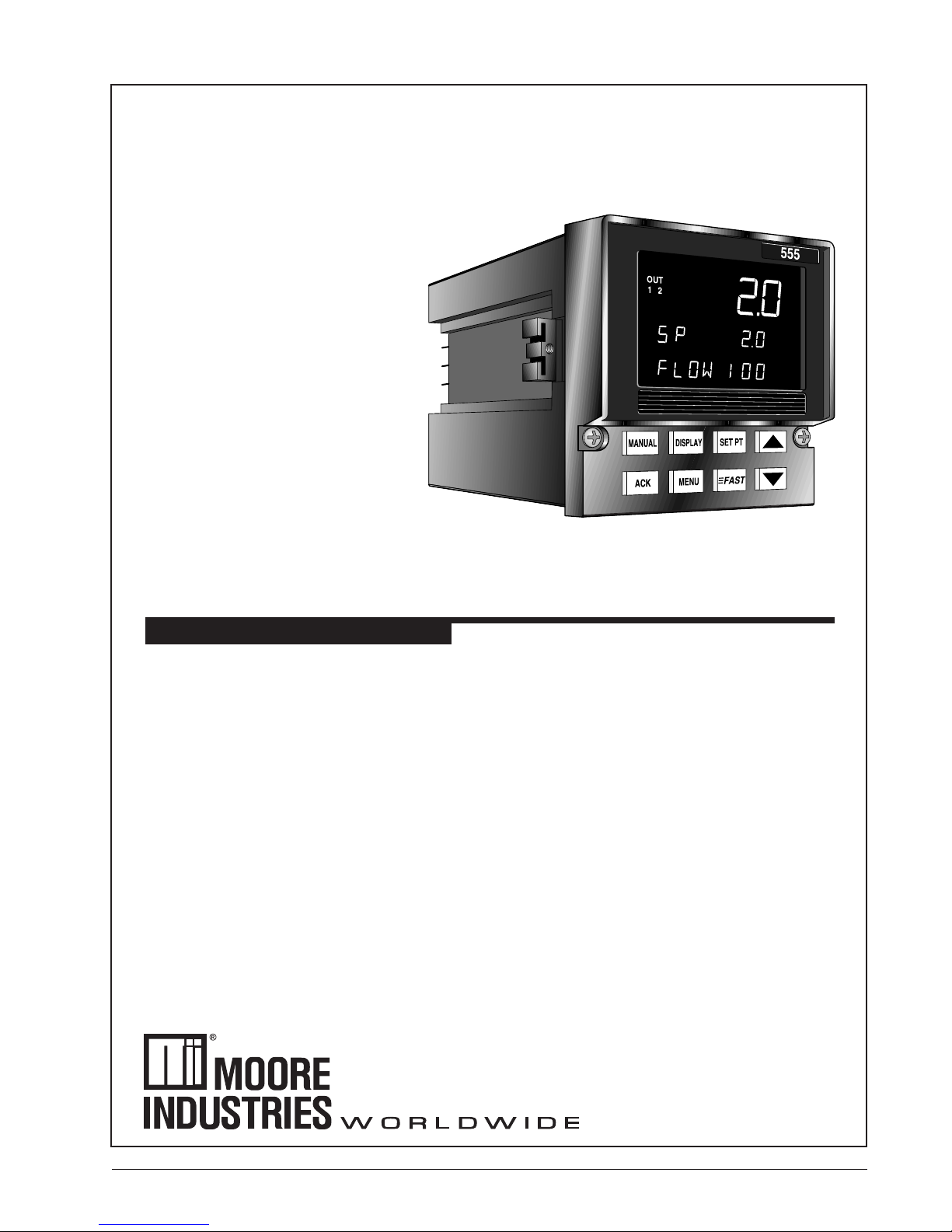
CHLORINATION/DECHLORINATION
CONTROLLER USER'S MANUAL
M555 V8, M
ARCH
201
7
Page 2

page
TABLE OF CONTENTS............................................................................. i
FIGURE LIST ........................................................................................... iii
CHAPTER 1
GENERAL INFORMATION ............................................................... 1
555 Control Modes ............................................................................ 1
555 Operation ................................................................................... 2
Order Code, Packaging Information .................................................. 2
Where To Go Next ............................................................................ 2
Text Formatting in This Manual ......................................................... 2
CHAPTER 2
BASIC INTERFACE .......................................................................... 5
Displays ............................................................................................ 5
Icons (Lit) .......................................................................................... 6
Keys .................................................................................................. 6
CHAPTER 3
HARDWARE SET UP ....................................................................... 7
Hardware Input Types ....................................................................... 7
The Process Variable ........................................................................ 7
The Remote Setpoint ........................................................................ 8
Mechanical Relays ............................................................................ 8
Accessing and Changing Jumpers .................................................... 9
Adding and Changing Output Modules ............................................ 10
Special Communications Module .................................................... 12
Contents
About This Manual:
Throughout this User’s Manual
information appears along the
margins, in the form of NOTEs,
CAUTIONs and WARNINGs, usually
in boldface. Please heed these
safety and good practice notices for
the protection of you and your
equipment.
CHAPTER 4
INSTALLATION .............................................................................. 13
Mounting the Controller ................................................................... 13
Wiring for Input and Outputs ........................................................... 14
AC Power Input ...................................................................... 14
Process Variables .................................................................. 15
Digital Inputs........................................................................... 17
Output Modules ...................................................................... 18
Remote Setpoint ..................................................................... 21
Serial Communications ........................................................... 21
CHAPTER 5
SOFTWARE CONFIGURATION..................................................... 23
Menus ............................................................................................. 23
Parameters ..................................................................................... 24
Configuration and Operation ........................................................... 24
Where to Go Next ........................................................................... 25
Software Menus and Parameters .................................................... 27
CONFIG ................................................................................. 27
CONTROL.............................................................................. 31
FLOW INPT. ........................................................................... 32
CUST.LINR. ........................................................................... 34
RSDL. INPT. .......................................................................... 35
SETPOINT ............................................................................. 36
REM. INPUT .......................................................................... 37
OUTPUT ................................................................................ 38
RETRANS. ............................................................................. 41
ALARMS ................................................................................ 43
555 User's Manual Table of Contents i
Page 3

Contents
page
POWER-UP ........................................................................... 47
SECURITY ............................................................................. 47
SER. COMM........................................................................... 48
TUNING ................................................................................. 49
Parameter Value Charts.................................................................. 51
CHAPTER 6
APPLICATIONS .............................................................................. 59
A. Flow Pacing Mode ...................................................................... 59
B. Residual Chlorine Loop Mode ..................................................... 61
C. Compound Loop Mode ............................................................... 64
D. Dechlorination Mode ................................................................... 67
E. Alarms ........................................................................................ 70
F. Slidewire Position Proportioning Output ...................................... 74
G. Staged Outputs ........................................................................... 75
H. Retransmission ........................................................................... 75
I. Digital Inputs ............................................................................... 76
J. Remote Input .............................................................................. 78
K. Integral Setting ............................................................................ 79
L. Tuning Tips ................................................................................. 80
M.Input Linearization ...................................................................... 83
N. Security ...................................................................................... 84
O. Process Variable Reading Correction ......................................... 85
P. Serial Communications ............................................................... 86
Q. Lag ............................................................................................. 87
APPENDIX A
ERROR HANDLING ..................................................................... A-1
Troubleshooting ............................................................................ A-1
Error Messages ............................................................................ A-2
APPENDIX B
CALIBRATION .............................................................................. B-1
Analog Input (V and mA) Calibration ............................................. B-1
Milliamp Output Calibration ........................................................... B-3
Reset Menu Data .......................................................................... B-4
Hardware Scan ............................................................................. B-4
Slidewire Test ............................................................................... B-5
Quick Calibration Procedure ......................................................... B-5
APPENDIX C
SPECIFICATIONS ........................................................................ C-1
APPENDIX D
FLOWCHARTS ............................................................................. D-1
Set Up and Tuning Mode Menus and Parameters ........................ D-1
APPENDIX E
GLOSSARY .................................................................................. E-1
APPENDIX F
ISOLATION BLOCK DIAGRAM .................................................... F-1
APPENDIX G
PARTS LIST ................................................................................. G-1
ii Table of Contents 555 User's Manual
Page 4

Figure.............Title ............................................................................ Page
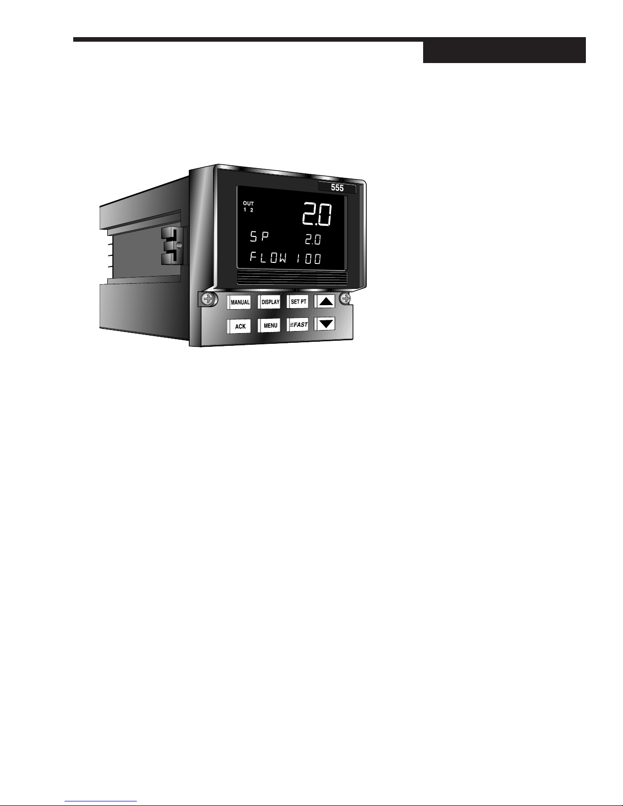
Figure 1.1 ........ The 555 Chlorination/Dechlorination Controller................. 1
Figure 2.1 ........ 555 Operator Interface ...................................................... 5
Figure 3.1 ........ Accessing the 555 Circuit Boards ..................................... 7
Figure 3.2 ........ The Microcontroller Circuit Board,
The Option Board, and the Power Supply Board ............... 8
Figure 3.3 ........ Output Module ................................................................ 11
Figure 3.4 ........ Install Communications Module onto the
Microcontroller Board ...................................................... 12
Figure 4.1 ........ Controller Dimensions. .................................................... 13
Figure 4.2 ........ Insert Mounting Clips ...................................................... 13
Figure 4.3 ........ 555 Input and Output Wiring Options .............................. 14
Figure 4.4 ........ AC Power Input Wiring .................................................... 15
Figure 4.5 ........ PV Voltage Input Wiring .................................................. 15
Figure 4.6 ........ PV mA Input with External Power Supply Wiring ............. 16
Figure 4.7 ........ PV mA Input with Internal Power Supply and
2-Wire Transmitter Wiring ................................................ 16
Figure 4.8 ........ PV mA Input with Internal Power Supply and
4-Wire Transmitter Wiring ................................................ 17
Figure 4.9 ........ Digital Input Wiring with a Switch or Relay ...................... 17
Figure 4.10 ...... Digital Input Wiring with an Open Collector ..................... 18
Figure 4.11 ...... Mechanical Relay Output Wiring ..................................... 18
Figure 4.12 ...... Solid State Relay Output Wiring ...................................... 19
Figure 4.13 ...... DC Logic Output and Milliamp Output Wiring ..................19
Figure 4.14 ...... Position Proportioning Output
with Slidwire Feedback Terminals ................................... 20
Figure 4.15 ...... Remote Setpoint Terminals ............................................. 21
Figure 4.16 ...... Serial Communications Terminals ................................... 21
Figure 5.1 ........ Menus, Parameters and Values ...................................... 23
Figure 5.2 ........ Independent vs. Dependent Parameters ......................... 24
Figure 5.3 ........ Operation and Configuration Flowchart ...........................24
Figure 6.1 ........ Flow Pacing Control ........................................................ 59
Figure 6.2 ........ Residual Chlorine Loop Control ...................................... 61
Figure 6.3 ........ Compound Loop Control ................................................. 64
Figure 6.4 ........ Dechlorination Control .................................................... 67
Figure 6.5 ........ Alarm Examples .............................................................. 73
Figure 6.6 ........ Residual Control Responses .......................................... 81
Figure 6.7 ........ Square Root Linearization Formula................................. 83
Figure 6.8 ........ Custom Linearization Curve............................................ 84
Figure 6.9 ........ Compound Loop Flow Pacing with Lag Times ................. 87
Figure B.1 ........ Calibration Menu Flowchart .......................................... B-1
Figure B.2 ........ Microcontroller Circuit Board ......................................... B-2
Figure B.3 ........ PV1 & PV2 Calibration Wiring ....................................... B-2
Figure B.4 ........ Milliamp Output Calibration Wiring ................................ B-3
Figure B.5 ........ Output Module Menu Cycle ........................................... B-4
Figure B.6 ........ Slidewire Calibration Wiring .......................................... B-5
Contents
555 User's Manual Table of Contents iii
Page 5

Contents
iv Table of Contents 555 User's Manual
Page 6
CHAPTER 1
GENERAL INFORMATION
General Information
Figure 1.1
The 555 Chlorination/Dechlorination
Controller
Automatic and accurate control of chlorine in potable and waste water is
more important than ever due to health and regulatory concerns. Poor
control can lead to failure of biomonitoring tests, leading to an even more
costly “Toxicity Reduction Evaluation.” The 555 is a cost effective way to
upgrade chlorination and dechlorination processes in an easy to use,
rugged 1/4 DIN size package. The 555 can be easily set up to handle flow
proportional control, residual control, compound loop control with lag times,
and dechlorination with sulfur dioxide.
Designed with the needs of the water and wastewater industry in mind, the
555 offers features that set it apart from the competition. The front panel is
NEMA 4X rated for protection from water and corrosion. The vacuum fluorescent display is bright and crisp, offering the best readability in all light
conditions. All prompts are displayed in easy to understand terms, with two
fully alphanumeric displays. An extra large third display is dedicated to
indicating one of the measured variables. When performing Compound Loop
Flow Pacing control, the 555 clearly displays both flow rate and residual
chlorine level simultaneously. The sturdy rubber keys are large and backlit
with excellent tactile feel.
The 555 is designed to quickly integrate with your flow transmitters and
residual analyzers through straightforward menu configuration selections.
555 CONTROL MODES
FLOW PACING MODE: control mode for adding chlorine to and/or removing
chlorine from the water, based on flow rate with no feedback.
RESIDUAL CHLORINE MODE: control mode for adding chlorine to the water
based on residual level as the process variable.
COMPOUND LOOP MODE: control mode for adding chlorine based on a
combination of both flow pacing and residual level.
DECHLORINATION MODE: the control output for adding SO2 to the water
based on a combination of both flow pacing and residual chlorine level.
555 User's Manual Chapter 1 1
Page 7

General Information
555 OPERATION
There are 3 operation “modes” for the 555 controller:
OPERATING, the default mode of the controller. While the 555 is “operating,”
you can change dosage setpoints, select manual control and change output level,
acknowledge alarms and monitor conditions.
SET UP, sometimes referred to as “configuration.” In set up, you configure the
basic functions of the instrument such as input and output assignments, alarm
types and special functions.
TUNING, where you configure control function parameters for Residual and
Compound Loop control. Use the tuning function periodically to optimize the
performance of the 555.
Refer to Chapter 5, and Figure 5.3, to view the relationship between these 3
modes.
ORDER CODE, P A CKAGING INFORMATION
Compare the product number on your controller (the label on top of the controller) with the order code on the next page. From this number you can confirm the
options on your 555.
In the controller packaging, you should have received:
• one 555 controller
• one 555 User’s Manual
• 555 mounting hardware
• one sheet engineering unit adhesive labels
• one rear terminal label
WHERE TO GO NEXT
• To become more familiar with the 555 interface, continue to Chapter 2.
• For important hardware installation guidelines, see Chapters 3 and 4.
• For a detailed description of all the software menus and parameters of the
555, follow through Chapter 5. Appendix D can be used as a basic guideline
to these parameters.
TEXT FORMA TTING IN THIS MANU AL
Feature Format
KEYS SET PT DISPLAY
or
SET PT DISPLAY
ICONS OUT, ALM
MENUS CONFIG., TUNING,
PARAMETERS CYCLE TM:1, MIN.OUT2
PARAMETER VALUES OFF, SETPOINT, LAST OUT.
DISPLAY MESSAGES TOO HOT, OUT%,
2 Chapter 1 555 User's Manual
Page 8
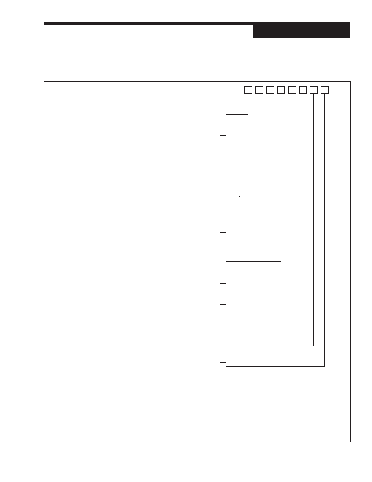
ORDER CODE
General Information
OUTPUT 1 —
CONTROL
OUTPUT 2 —
CONTROL,
ALARM,
OR
RETRANSMISSION
OUTPUT 3 —
ALARM,
OR
RETRANSMISSION
OUTPUT 4 —
ALARM,
RETRANSMISSION,
OR LOOP POWER
None .......................................................... 0
Mechanical relay (5 amp) ........................... 1
Analog (milliamp) ....................................... 2
Solid state relay (triac) (1 amp) ...................3
DC logic (SSR drive) .................................. 4
None .......................................................... 0
Mechanical relay (5 amp) ........................... 1
Analog (milliamp) ....................................... 2
Solid state relay (triac) (1 amp) ...................3
DC logic (SSR drive) .................................. 4
None .......................................................... 0
Mechanical relay (5 amp) .......................... 1
Analog (milliamp) ....................................... 2
Solid state relay (triac) (1 amp) .................. 3
DC logic (SSR drive) ................................. 4
None .......................................................... 0
Mechanical relay (0.5 amp, 24 V) .............. 1
Analog (milliamp) ....................................... 2
Solid state relay (triac) (0.5 amp, 24 V) ..... 3
DC logic (SSR drive) ................................. 4
Loop power................................................ 5
B
0 0555 -
Optional Inputs
ENTER “0” IF
OPTIONAL
NOT DESIRED
INPUT
Slidewire feedback for
position proportioning
output ........................................................ A
Remote setpoint (Standard) ....................... B
Five digital inputs (for vacuum alarm and
stand by mode) .......................................... D
SERIAL
COMMUNICATIONS
ENTER
“0” IF
RS-485 serial
communications......................................... S
COMMUNICATIONS
NOT
DESIRED
Note 1: Capability for position proportioning output is specified by ordering 555-11xxAxxx00, 555-33xxAxxx00,
or 555-44xxAxxx00. (Slidewire not required for velocity proportioning.) Note 2: Up to two outputs may be
used for alarms. Note 3: All outputs are interchangeable modules. Note 4: The mechanical relay and solid
state relay modules are derated to 0.5 amp at 24 Vac when used as the fourth output.
555 User's Manual Chapter 1 3
Page 9

General Information
4 Chapter 1 555 User's Manual
Page 10
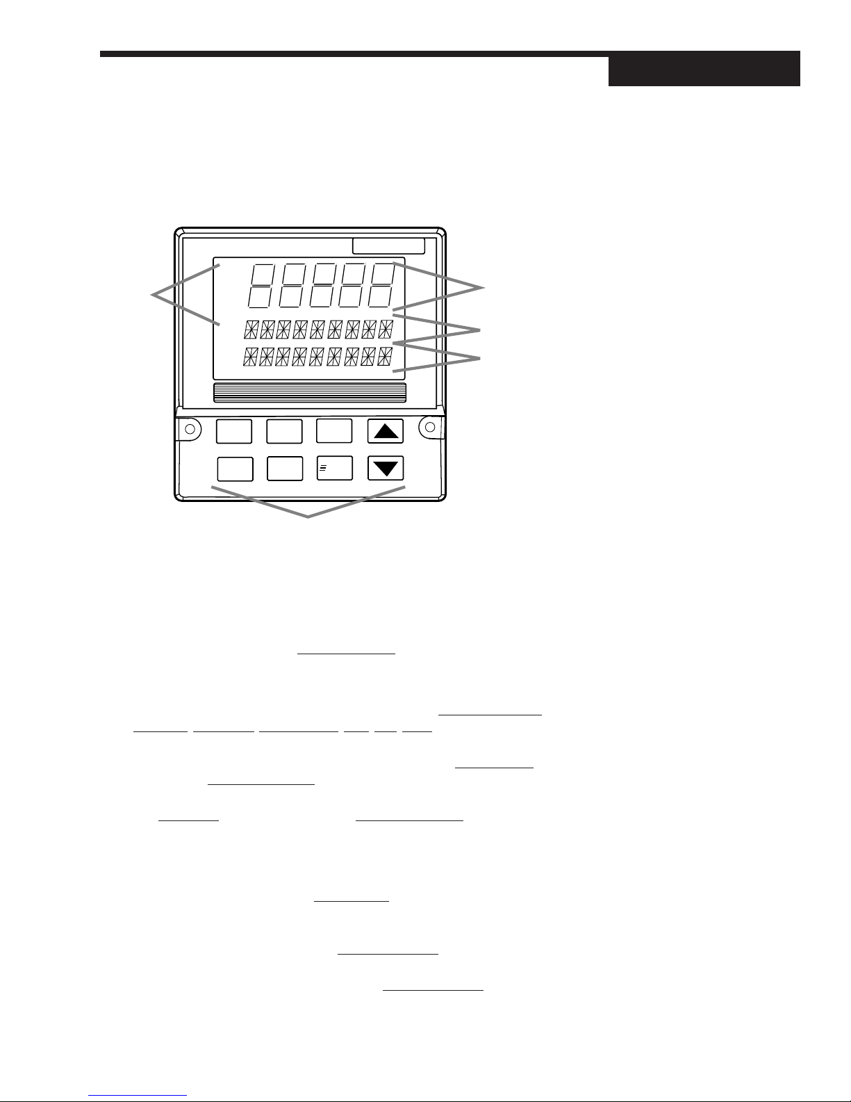
CHAPTER 2
BASIC INTERF A CE
Interface
Icons
OUT
1 2
ALM
1 2
555
Displays:
1st
2nd
3rd
MANUAL
ACK
DISPLAY
MENU
SET PT
FAST
Keys
DISPLAYS
Refer to Chapter 6 for details on the interface functions for specific modes.
1st Line (five 7-segment digits)
• Always displays a (primary) process variable, with value/units depending
on the individual mode.
2nd Line (nine 14-Segment Digits)
• Under “normal” operating conditions, displays process dosage or
setpoints, deviations, output values, lags, trim, pace, etc., depending upon
the mode.
• When configuring the 555 (in any mode), displays the menu names and
subsequent parameter names.
• When using a ramping setpoint that is actively ramping, alternates between
the target SP (SP2, RSP) and the ramping setpoint (which causes
RAMPING to show in the third display).
• When using the slidewire option, displays the actual valve position.
3rd Line (nine 14-Segment Digits)
• For dual PV modes shows the alternate PV, whether it is flow or residual
level. To switch the display positions of the primary and secondary PV,
press FAST + DISPLAY.
• If alarms occur, this line will show alarm messages alternating with any
other messages.
• During configuration, this line shows the parameter value in the menu
system.
Figure 2.1
555 Operator Interface
555 User's Manual Chapter 2 5
Page 11

Interface
OUT OUT OUT
1212
ALM ALM ALM
1212
PV2
ICONS (LIT)
OUT1 Indicates the output is at a level greater than 0%, or “activated” (for time
OUT2 Indicates the second output (SO
ALM1 Indicates the respective alarm (one) is active.
ALM2 Indicates the respective alarm (one) is active.
PV2 Indicates that the flow input (PV2) is in the 1st display.
KEYS
FAST: Has no independent function - press to modify the function of another
key (see below).
MANUAL : Press to toggle between manual and automatic control. When lit,
indicates that the unit is under manual control.
FAST+MANUAL : Press to transfer controller from manual to automatic control
when setting up bumpless transfer dosage values. Refer to Chapter 6 for more
information about bumpless transfer and dosage values.
SET PT : Press to select the active SP. When lit, indicates that a setpoint other
than the primary (e.g., RSP, SP2) is active.
DISPLAY
DISPLAY
MANUAL
MANUAL
+
SET PT
proportioning or a digital output).
2
staging or slidewire output is active.
) of the duplex flow pacing mode,
FAST
FAST
FAST
FAST
DISPLAY
DISPLAY
+
+
+
+
▲
▲
▼
▼
MENU
MENU
DISPLAY : Press to step through the values (SP, %OUT, DOSAGE, etc.) to be
shown in the 2nd display.
FAST+DISPLAY : Allows user to switch display positions of the PV1 (residual)
and PV2 (flow) between the 1st and 3rd displays.
▲▲
▲ : Press to advance to previous value or parameter
▲▲
FAST+
▼▼
▼ : Press to advance to next value or parameter
▼▼
FAST+
ACK : Press to acknowledge (an) alarm(s). When lit, indicates that there is an
acknowledgeable alarm.
MENU : Press to access the Tuning Menu, and its parameters. When lit, indicates
that the controller is in Set Up mode (in the configuration menus).
FAST+MENU : Press to access the Set Up menus. Use MENU to access the
parameters of the software menus. When lit, indicates that the controller is in
Set Up mode (in the configuration menus).
▲▲
▲ : Press to scroll through values at a faster rate.
▲▲
▼▼
▼ : Press to scroll through values at a faster rate.
▼▼
6 Chapter 2 555 User's Manual
Page 12
CHAPTER 3
HARDW ARE SET UP
Hardware
The configuration of the hardware in your controller determines the available
outputs as well as the type of input signal. Your 555 controller comes factory
set with the following:
• All the specified modules and options installed. (For more details, refer to
the order code in Chapter 1.)
• Process variable, setpoint and/or valve position inputs set to accept a
milliamp input
• Relay outputs set to normally open
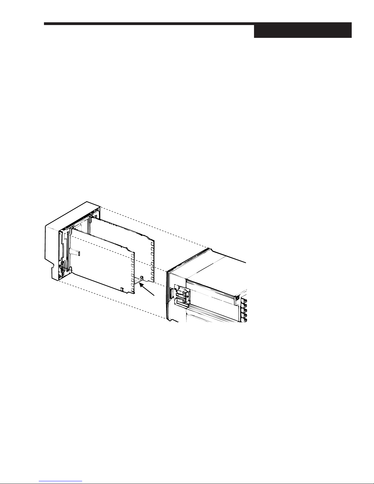
To alter the factory configuration of your 555, you will need to access the 555
circuit boards, and locate the jumpers and output modules on the circuit boards
(see Figure 3.1):
1. With power off, loosen two front screws, and remove them.
2. Slide the chassis out of the case by pulling firmly on the bezel.
MICROCONTROLLER
BOARD
POWER SUPPLY
BOARD
NOTE:
If you would like your controller
configured at the factory, please
consult an application engineer.
NOTE:
Your hardware configuration will
influence the available software
options as discussed in Chapter 3.
Figure 3.1
Accessing the 555 Circuit Boards
OPTION
BOARD
A detailed view of the circuit boards appears in Figure 3.2.
After configuring the hardware, or if you do not need to make any changes, con-
tinue your process set up as needed.
HARDW ARE INPUT TYPES
The Process Variable
The 555 accepts both voltage and milliamp process variable signals. You must
set a jumper location to specify the type of input signal. You set the particular
range in the software (see Chapter 5 for software menus, or Chapter 6 for applications).
The jumpers for the process variable are located on the Microcontroller Circuit
Board (see Figure 3.2). The factory default is Milliamp. Locations are marked
as follows:
V Voltage
MA Milliamp
555 User's Manual Chapter 3 7
NOTE:
Any changes you make to the output
modules will render the code on the
product label invalid.
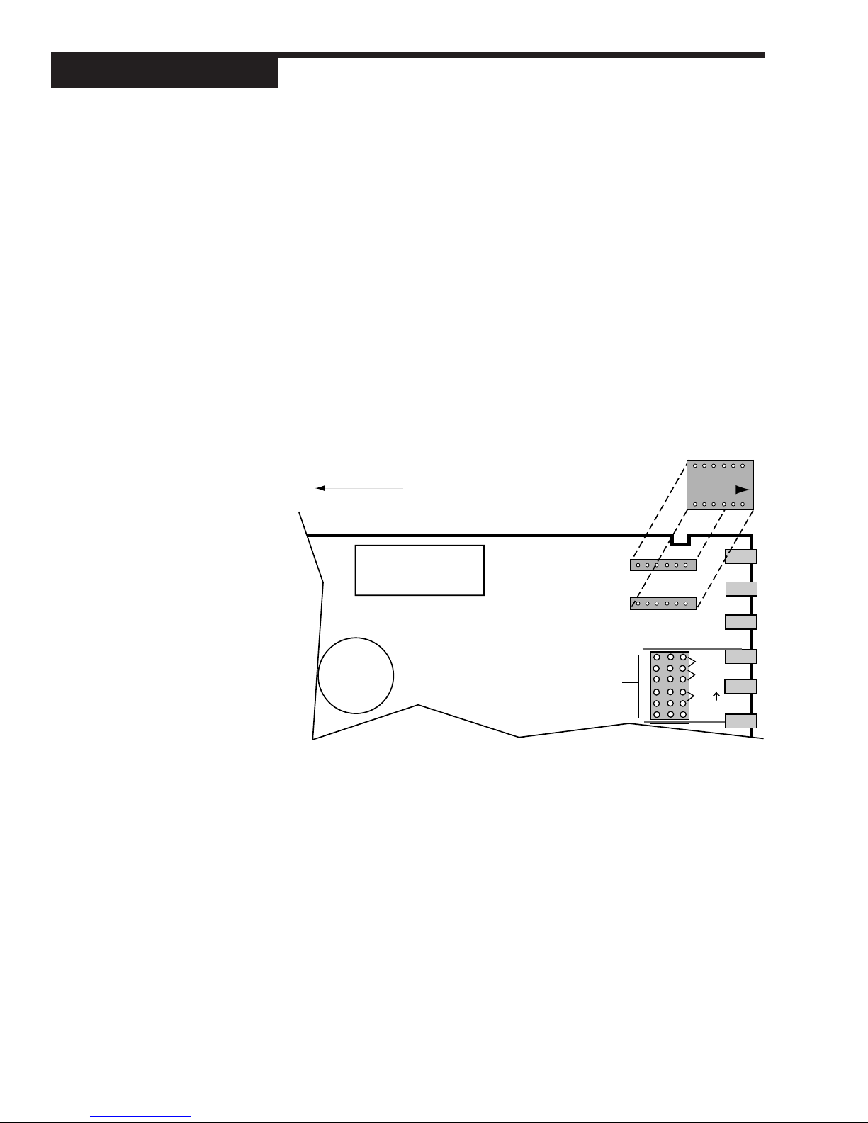
Page 13
Hardware
BATTERY
EPROM
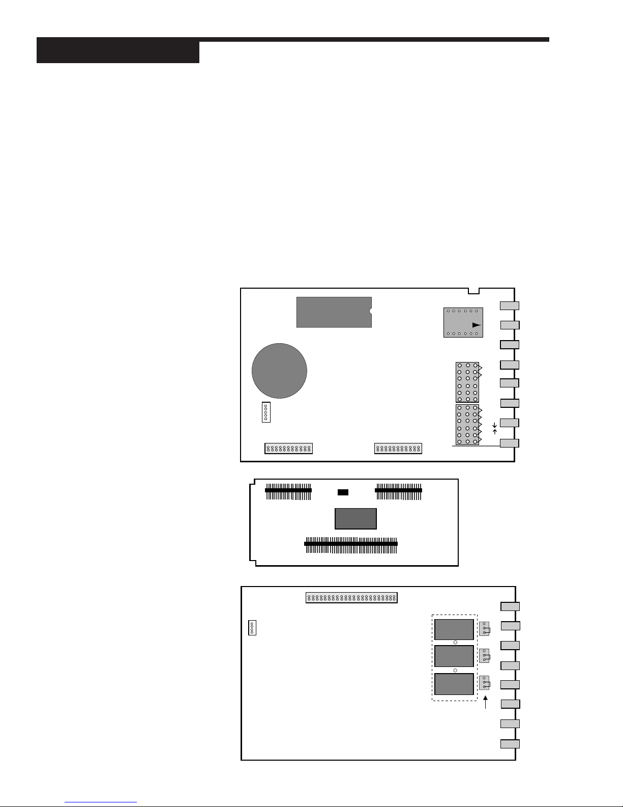
Figure 3.2
(from the top) The Microcontroller
Circuit board, The Option Board,
and the Power Supply Board
The Remote Setpoint
Figure 3.2 shows the location of the remote setpoint jumper. The factory default
is Milliamp. Choose from the following settings:
V Voltage
MA Milliamp
Mechanical Relays
There are three output module sockets on the Power Supply Circuit Board,
and one output module on the Option Board (see Figure 3.2). The mechanical relay on the Power Supply Board may be configured for either normally
open (NO) or normally closed (NC). A jumper located next to each socket de-
termines this configuration. All the relay outputs are factory set to NO
(normally open).
EPROM
Comm Module
TB2
BATTERY
5-Pin Connector
Female 22-Pin ConnectorFemale 22-Pin Connector
V
MA
V
MA
TC
TC
RTD
2ND
PV1
TB1
8 Chapter 3 555 User's Manual
Male 22-Pin
Connector
4-Pin Connector
Output 4
4
Female 44-Pin Connector
Male 22-Pin
Connector
Male 44-Pin
Connector
Module
Retention
Plate
over Outputs 1,2,3
3
2
1
NO J3 NC
NO J2 NC
NO J1 NC
Jumpers
NO and NC
Page 14
ACCESSING AND CHANGING JUMPERS
Follow these instructions to change jumpers for the Process Variable, Remote
Setpoint and Digital Inputs:
Equipment needed: Needle-nose pliers (optional)
Phillips screwdriver (#2)
Wrist grounding strap
1. With power off, loosen two front screws, and remove them.
2. Slide the chassis out of the case by pulling firmly on the bezel.
3. Use Figure 3.2 to help you locate the jumper connector that you intend to
change.
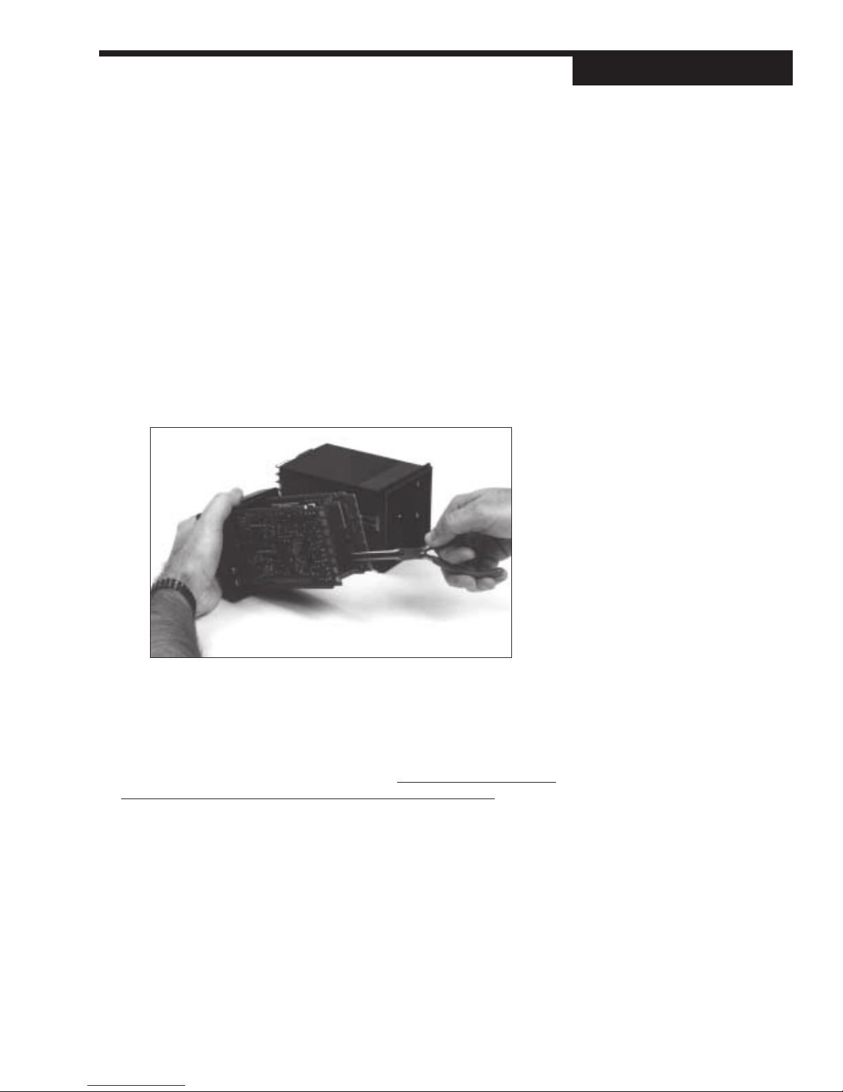
4. Using either your fingers or the needle nose pliers, pull straight up on the
connector and remove it from its pins, as shown in Photo 4. Be careful not
to bend the pins.
Hardware
4. Remove Jumpers
5. Find the new location of the jumper connector (again, refer to Figure 3.2).
Carefully place it over the pins, then press connector straight down. Make
sure it is seated firmly on the pins.
6. Make any other jumper changes as needed.
modules, please refer to the next section, starting with Step #3.
7. To reassemble the controller, properly orient the chassis with board opening on top. Align the circuit boards into the grooves on the top and bottom of
the case. Press firmly on the front face assembly until the chassis is all the
way into the case.
If you have difficulty sliding the chassis in all the way, make sure you have
removed the screws (they can block proper alignment), and that the chassis is properly oriented.
8. Carefully insert and align screws. Tighten them until the bezel is seated firmly
against the gasket. Do not overtighten.
555 User's Manual Chapter 3 9
If you need to alter output
Page 15
Hardware
ADDING AND CHANGING OUTPUT MODULES
The 555 has provisions for four output modules. A controller ordered with
output module options already has the modules properly installed. Follow
these instructions to add modules, change module type(s) or change module
location(s).
Equipment needed: Wrist grounding strap
Phillips screwdriver (#2)
Small flat blade screwdriver
Wire cutters
1. With power off, loosen two front screws, and remove them.
2. Slide the chassis out of the case by pulling firmly on the bezel.
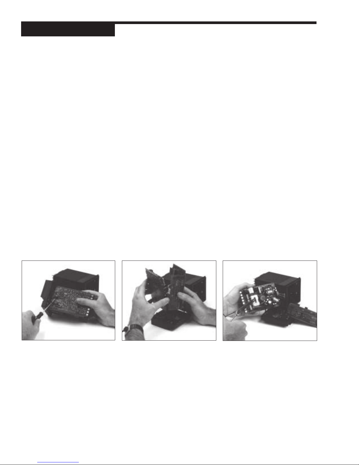
3. Use a flat screwdriver to carefully pry apart the clips that hold the front
face assembly to the chassis, as in Photo 3. Separate the printed circuit
board assembly from the front face assembly. Use care not to break the
clips or scratch the circuit boards.
4. As shown in Photo 4, use your hands, or the flat screwdriver, to carefully
pry apart the smaller Option board and the Power Supply board (the one
with 3 modules).
5. If you need to change modules 1, 2 or 3:
Output modules 1, 2, and 3 are firmly held in place by a retention plate
and tie wrap. Carefully snip the tie wrap with a wire cutter. To prevent
damage to the surface mount components, ALWAYS snip the tie wrap on
TOP of the Retention Plate, as shown in Photo 5.
Remove the retention plate.
3. Pry Clips
10 Chapter 3 555 User's Manual
4. Separate Boards
5. Remove Retention Plate
Page 16

6. If you need to change module 4:
Output Module 4 (on the Option board) is also held in place by a tie wrap.
Snip tie wrap to remove module as shown in Photo 6.
7. Figure 3.3 shows a representation of an output module. Inspect your
module(s) to make sure that the pins are straight.
8. To install any module, align its pins with the holes in the circuit board, and
carefully insert the module in the socket. Press down on the module until
it is firmly seated; refer to Photo 8.
Hardware
Figure 3.3
Output Module
6. Snip Tie Wrap
9. Replace tie wraps for all the modules (the Retention Plate and Output
Module 4) with new ones before you reassemble.
Failure to use the tie wraps may result in loosening of the module and
eventual failure. All separately ordered modules should come with a tie
wrap. Extra sets of tie wraps are available by ordering Part #555-665.
10.Rejoin the circuit boards by aligning the pins of their connectors, then
squeezing the board(s) together. Make sure that all three printed circuit
boards are properly seated against one another; check along side edges
for gaps. Make sure the cable assemblies are not pinched.
11.To reattach the board assembly to the front face assembly, align the
boards (with the open area on top) into the slots of the font face assembly. The clips should snap into place.
12.To reassemble the controller, properly orient the chassis with board
opening on top. Align the circuit boards into the grooves on the top and
bottom of the case. Press firmly on the front face assembly until the
chassis is all the way into the case.
If you have difficulty sliding the chassis in all the way, make sure you
have removed the screws (they can block proper alignment), and that the
chassis is properly oriented.
13.Carefully insert and align screws. Tighten them until the bezel is seated
firmly against the gasket. Do not overtighten.
8. Add/Change Module
NOTE: For greatest accuracy,
calibrate all milliamp modules added
for retransmission as per the
instructions in Appendix B.
SPECIAL COMMUNICA TIONS MODULE
555 User's Manual Chapter 3 11
Page 17
Hardware
A special communications module is available for the 555; see order code in
Chapter 1 for details.
Equipment needed: Wrist grounding strap
Phillips screwdriver (#2)
Small flat blade screwdriver
1. Before you install the communications module, set up the hardware wiring
for your application. See Chapter 4 for details.
2. With power off, loosen two front screws, and remove them.
3. Slide the chassis out of the case by pulling firmly on the bezel. Do not detach
the board assembly from the front face of the controller.
4. Orient the Communications Module with the arrow pointing towards the rear
of the 555 unit, and attach it to Connectors P1 and P2 as shown in Figure
3.4.
5. To reassemble the controller, properly orient the chassis with board open-
Insert module onto connectors.
Make sure arrow on module
points toward rear terminals.
Figure 3.4
Install Communications Module onto
Microcontroller Board
Front of controller
(circuits boards still attached to front face)
EPROM
P2
P1
TB2
(REMOTE SP
BATTERY
OR
DIGITAL INPUT)
CONFIGURATION
ing on top. Align the circuit boards into the grooves on the top and bottom of
the case. Press firmly on the front face assembly until the chassis is all the
way into the case.
If you have difficulty sliding the chassis in all the way, make sure you have
removed the screws (they can block proper alignment), and that the chassis is properly oriented.
6. Carefully insert and align screws. Tighten them until the bezel is seated firmly
against the gasket. Do not overtighten.
V
MA
TC
2ND
12 Chapter 3 555 User's Manual
Page 18
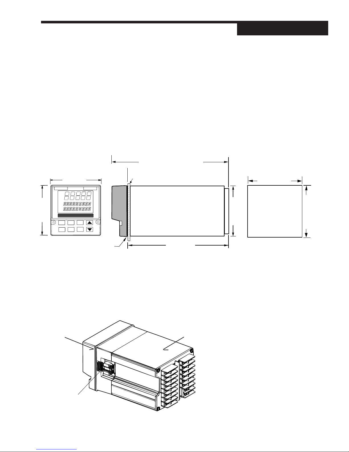
CHAPTER 4
INSTALLA TION
MOUNTING THE CONTROLLER
The front face of the 555 is NEMA 4X rated. To obtain a waterproof seal between the controller and the instrument panel, follow these directions:
1. The 555 fits in a standard 1/4 DIN cutout. You may mount your 555 in any
panel with a thickness from 0.06 in. to 0.275 in. (1.5mm to 7.0mm).
2. Figure 4.1 shows controller and panel dimensions. The panel cutout must
be precise, and the edges free from burrs and waves.
7.180 (182.37) OVERALL LENGTH
1.180 (29.97)
3.770 (95.76)
PANEL
Installation
Figure 4.1
Controller Dimensions
3.622 (92.00) MIN.
3.653 (92.80) MAX.
OUT
1 2
ALM
1 2
3.770 (95.76)
6.000 (152.40)
SIDE
FRONT
BEZEL
GASKET
3. Place a new bezel gasket around the controller case, starting at the back of
controller. Then, slide the gasket up against the back of the bezel. To ensure a good seal, always use a fresh gasket.
4. With the bezel gasket in place, insert the 555 into the panel cutout from the
front of the panel. The case of the controller must be centered in the cutout.
5. From behind the panel, insert the mounting clips (one on each side), as
shown in Figure 4.2.
3.585 (91.06)
CUTOUT
Figure 4.2
Insert Mounting Clips
3.622 (92.00) MIN.
3.653 (92.80) MAX.
MOUNTING BRACKET
(1 EA. SIDE)
BEZEL
555 User's Manual Chapter 4 13
Slide
gasket on
from this
end.
HOUSING
Page 19

Installation
6. Gradually tighten the mounting bracket screws with a long Phillips screw
driver (#2). Make sure the screws are secure, and check the bezel gasket
for a tight, even seal.
7. If you have difficulty with any of the mounting requirements, apply a bead of
caulk or silicone sealant behind the panel around the perimeter of the case.
WIRING FOR INPUT AND OUTPUTS
555 controllers are thoroughly tested, calibrated and “burned in” at the factory,
so your controller is ready to install. Before you begin wiring your system, read
this section thoroughly and take care in planning your system. A properly designed system can help prevent problems such as electrical noise disturbances
and dangerous extreme conditions.
Special Notes:
1. For improved electrical noise immunity, install the 555 as far away as possible from motors, relays and other similar noise generators.
2. Do not run low power (sensor input) lines in the same bundle as AC power
lines. Grouping these lines in the same bundle can create electrical noise
interference.
3. All wiring and fusing should conform to the National Electric Code and to
any locally applicable codes.
4. An excellent resource about good wiring practices is the IEEE Standard No.
518-1982 and is available from IEEE, Inc., 345 East 47th Street, New York,
NY 10017, (212) 705-7900.
Rear terminal diagrams on the next pages are guides for wiring the different
types of inputs and outputs for the 555. Remember that the installed output
modules (Chapter 3) determine which inputs and outputs are available, and your
software set up (Chapter 5) will determine how your instrument controls.
Figure 4.3
555 Input and Output Wiring
Digital Inputs Option (if installed)Slidewire Option Input
Options
AC Power
Flow Pacing, Residual, Compound Loop:
CL2 valve output (4-20mA or Relay)**
Dechlorination:
SO2 valve output (4-20mA or Relay)**
Dual Flow Pacing:
SO2 valve output (4-20mA or Relay)**
Alarm Relay/Retransmission:
2nd staged output (4-20mA)**
2nd slidewire output (relay)**
Alarm Relay/ Retransmission**
** Outputs 1, 2, 3 and 4 must be filled
with appropriate modules. See Chapter 3.
LINE
NEUTRAL
OUT 1–
OUT 1+
OUT 2–
OUT 2+
OUT 3–
OUT 3+
1
2
3
4
5
6
7
8
Alarm Relay/ Retransmission**
9
10
11
12
13
14
15
16
EARTH
GND
S/W
CCW
S/W2
S/W3
RSP–
RSP+
OUT 4–
OUT 4+
DIN
17
GND
DIN 1
18
DIN 2
19
DIN 3
20
DIN 4
21
DIN 5
22
N/A
23
N/A
24 32
Remote Set Point Option Input
25
26
27
28
29
30
31
N/A
RS485–
RS485+
PV2–
PV2+
N/A
PV1–
PV1+
RS485 Com
(if installed)
Flow signal input
4-20mA from transmitter
CL2 signal input
4-20mA from analyzer
14 Chapter 4 555 User's Manual
Page 20
AC P ower Input
Installation
Terminals 1 and 2 are for POWER. Terminal 9 is earth ground. Use a 0.5
Amp, 250 V fast-acting fuse in line with your AC power connection.
AC LINE
AC NEUTRAL
1
2
7
8
Screws must be tight to ensure electrical connection
9
16
EARTH
GND
17
25
31
24 32
Process V ariables
Note:
On the actual 555, the only
terminals with printed numbers are
those shown in Figure 4.4.
Figure 4.4
AC Power Input Wiring
The 555 uses up to two process variables depending on the control mode:
PV1 is for Cl
residual level, and PV2 is for flow (rate). Each PV signal can be
2
either voltage or milliamp input.
1. Voltage Input (Figure 4.5)
• PV1 uses terminals 31 and 32 connected to a transmitter.
• PV2 uses terminals 28 and 29 connected to a transmitter.
1
2
3
4
5
6
7
8
Screws must be tight to ensure electrical connection
9
10
11
12
13
14
15
16
17
18
19
20
21
22
23
25
26
27
28
29
30
31
24 32
PV1–
PV1+
–
Transmitter
+
1
2
3
4
5
6
7
8
Screws must be tight to ensure electrical connection
9
10
11
12
13
14
15
16
Figure 4.5
PV Voltage Input Wiring
17
18
19
20
21
22
23
25
26
27
28
29
30
31
PV2–
PV2+
24 32
–
Transmitter
+
555 User's Manual Chapter 4 15
Page 21
Installation
1
2
3
4
5
6
7
8
16
15
14
13
12
11
10
9
17
18
19
20
21
22
23
24 32
31
30
29
28
27
26
25
Screws must be tight to ensure electrical connection
2-wire
transmitter
–
+
Input power can come from
a loop power module in
Output 2 (terminals 5 & 6),
Output 3 (terminals 7 & 8), or
Output 4 (terminals 15 & 16).
Transmitter output can
be connected to
PV1 (temrinals 31 & 32) or
PV2 (temrinals 28 & 29)
OUT 4–
OUT 4+
OUT 3–
OUT 3+
OUT 2–
OUT 2+
PV1–
PV1+
PV2–
PV2+
Figure 4.6
PV mA Input with External Power
Supply Wiring
2. Milliamp Input + External Power Supply (Figure 4.6)
• PV1 Milliamp Input with an external power supply uses terminals 31
and 32 with a 2-wire transmitter.
• PV2 Milliamp Input with an external power supply uses terminals 28
and 29 with a 2-wire transmitter.
1
2
3
4
5
6
7
8
Screws must be tight to ensure electrical connection
9
10
11
12
13
14
15
16
17
18
19
20
21
22
23
25
26
27
28
29
30
31
24 32
Figure 4.7
PV mA Input with Internal Power
Supply and 2-wire Transmitter
Wiring
PV1–
PV1+
External Power
Supply
–
Transmitter
–
1
2
3
4
5
6
+
+
7
8
Screws must be tight to ensure electrical connection
9
10
11
12
13
14
15
16
17
18
19
20
21
22
23
24 32
3. Milliamp Input + Internal (loop) Power Supply
If internal loop power is desired, a loop power module must be installed
in Output 2, 3 or 4. See Chapter 1 for details on your controller’s installed
options. See also Chapter 3 for module installation details.
2-wire Transmitter (Figure 4.7)
• PV1: terminals 31 and 32 with the loop power module output terminals, and a 2-wire transmitter.
• PV2: terminals 28 and 29 with the loop power module output terminals, and a 2-wire transmitter.
25
26
27
28
29
30
31
PV2–
PV2+
External Power
Supply
–
Transmitter
–
+
+
16 Chapter 4 555 User's Manual
Page 22
4-wire Transmitter (Figure 4.8)
• PV1: terminals 31 and 32 with the loop power module output terminals, and a 4-wire transmitter.
• PV2: terminals 28 and 29 with the loop power module output terminals, and a 4-wire transmitter.
Installation
Input power can come from
a loop power module in
Output 2 (terminals 5 & 6),
Output 3 (terminals 7 & 8), or
Output 4 (terminals 15 & 16).
Ð
Power for
transmitter
+
PV2–
PV2+
PV1–
PV1+
Ð
4-20mA
output from
transmitter
+
Transmitter output can
be connected to
PV1 (temrinals 31 & 32) or
PV2 (temrinals 28 & 29)
Input
OUT 2–
OUT 2+
OUT 3–
OUT 3+
1
2
3
4
5
6
7
8
9
10
11
12
13
14
15
16
OUT 4–
OUT 4+
17
18
19
20
21
22
23
25
26
27
28
29
30
31
24 32
Screws must be tight to ensure electrical connection
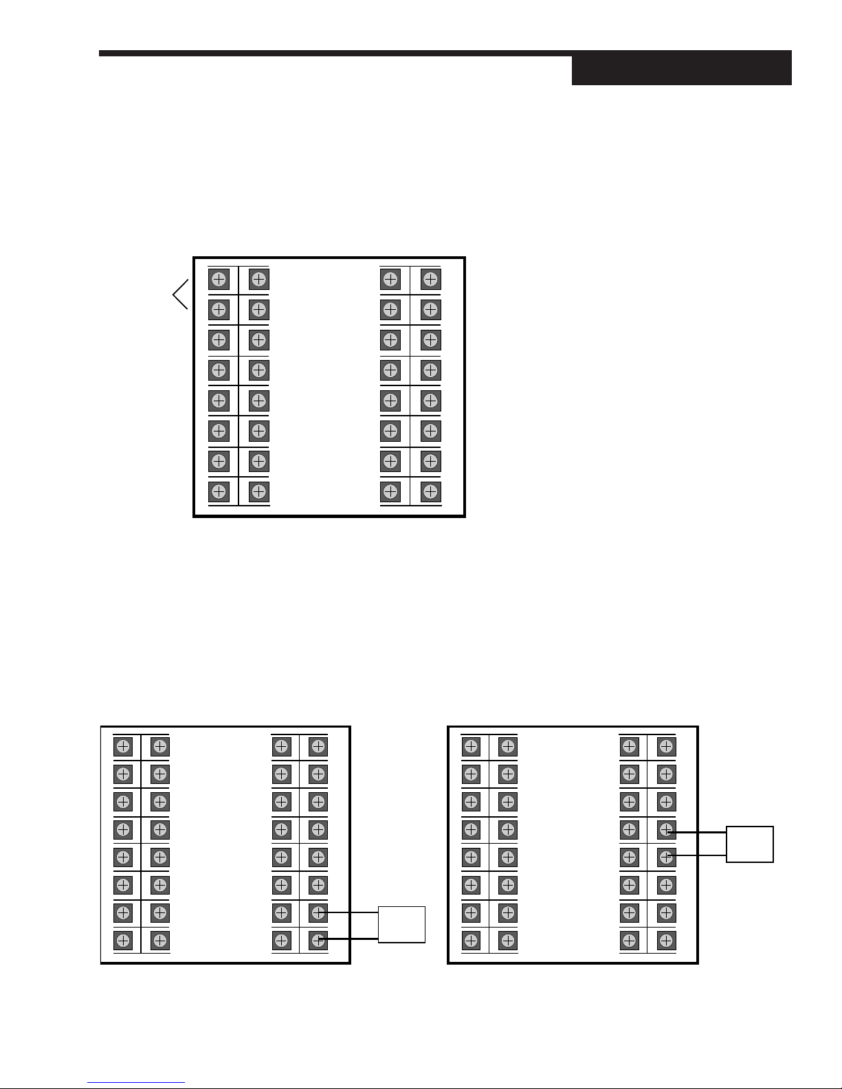
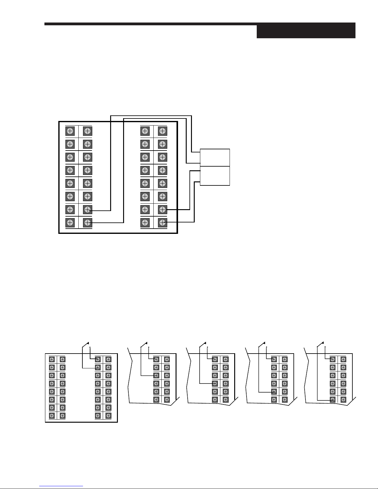
Digital Inputs
Digital inputs can be activated in three ways: a switch (signal type) - the recommended type, closure of a relay, or an open collector transistor.
Digital inputs are only functional when that option is installed (via hardware).
The controller detects the hardware type, and supplies the appropriate software
menu.
1. Digital Inputs with a switch or relay
Wire the switch/relay between terminal 17 and the specific digital input
terminal (Figure 4.9).
Figure 4.8
PV mA Input with Internal Power
Supply and 4-wire Transmitter Wiring
NOTE:
There are 14 contact types for the up
to 5 digital inputs - refer to Chapter 6
for a complete discussion.
1
2
3
4
5
6
7
8
Screws must be tight to ensure electrical connection
DIN
GND
DIN 1
DIN 2
DIN 3
DIN 4
DIN 5
17
18
19
20
21
22
23
24 32
9
10
11
12
13
14
15
16
25
26
27
28
29
30
31
555 User's Manual Chapter 4 17
GND
DIN 1
DIN 2
DIN 3
DIN 4
DIN 5
DIN
17
18
19
20
21
22 30
25
26
27
28
29
GND
DIN 1
DIN 2
DIN 3
DIN 4
DIN 5
DIN
17
18
19
20
21
22 30
25
26
27
28
29
DIN
GND
DIN 1
DIN 2
DIN 3
DIN 4
DIN 5
17
18
19
20
21
22 30
25
26
27
28
29
GND
DIN 1
DIN 2
DIN 3
DIN 4
DIN 5
DIN
17
18
19
20
21
22 30
25
26
27
28
29
Figure 4.9
Digital Input Wiring with a Switch or
Relay
Page 23
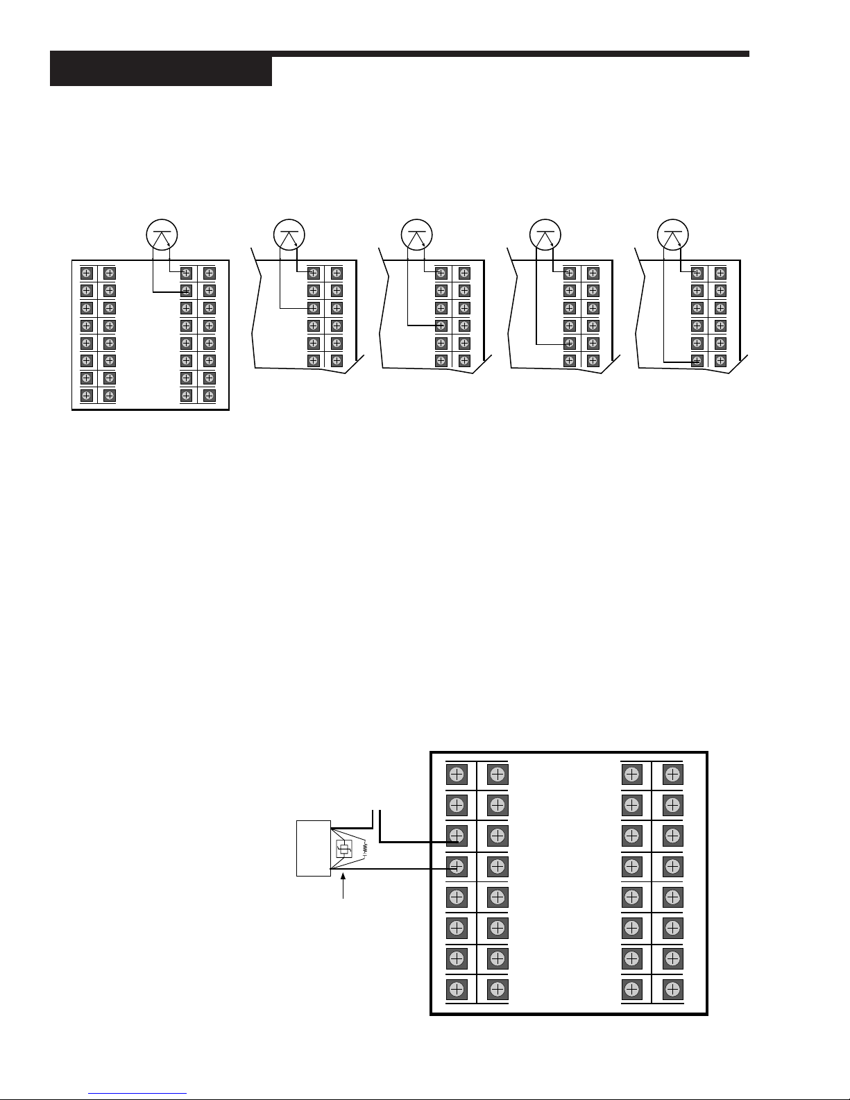
Installation
Figure 4.10
Digital Input Wiring with an Open
Collector (transistor)
1
2
3
4
5
6
7
8
Screws must be tight to ensure electrical connection
DIN
GND
DIN 1
DIN 2
DIN 3
DIN 4
DIN 5
17
18
19
20
21
22
23
24 32
9
10
11
12
13
14
15
16
25
26
27
28
29
30
31
2. Digital Inputs with an Open Collector
An open collector is also called a transistor. Wire the transistor between
terminal 17 and the specific digital input terminal (Figure 4.10)
GND
DIN 1
DIN 2
DIN 3
DIN 4
DIN 5
DIN
17
18
19
20
21
22 30
25
26
27
28
29
GND
DIN 1
DIN 2
DIN 3
DIN 4
DIN 5
DIN
17
18
19
20
21
22 30
25
26
27
28
29
GND
DIN 1
DIN 2
DIN 3
DIN 4
DIN 5
DIN
17
18
19
20
21
22 30
25
26
27
28
29
GND
DIN 1
DIN 2
DIN 3
DIN 4
DIN 5
DIN
17
18
19
20
21
22 30
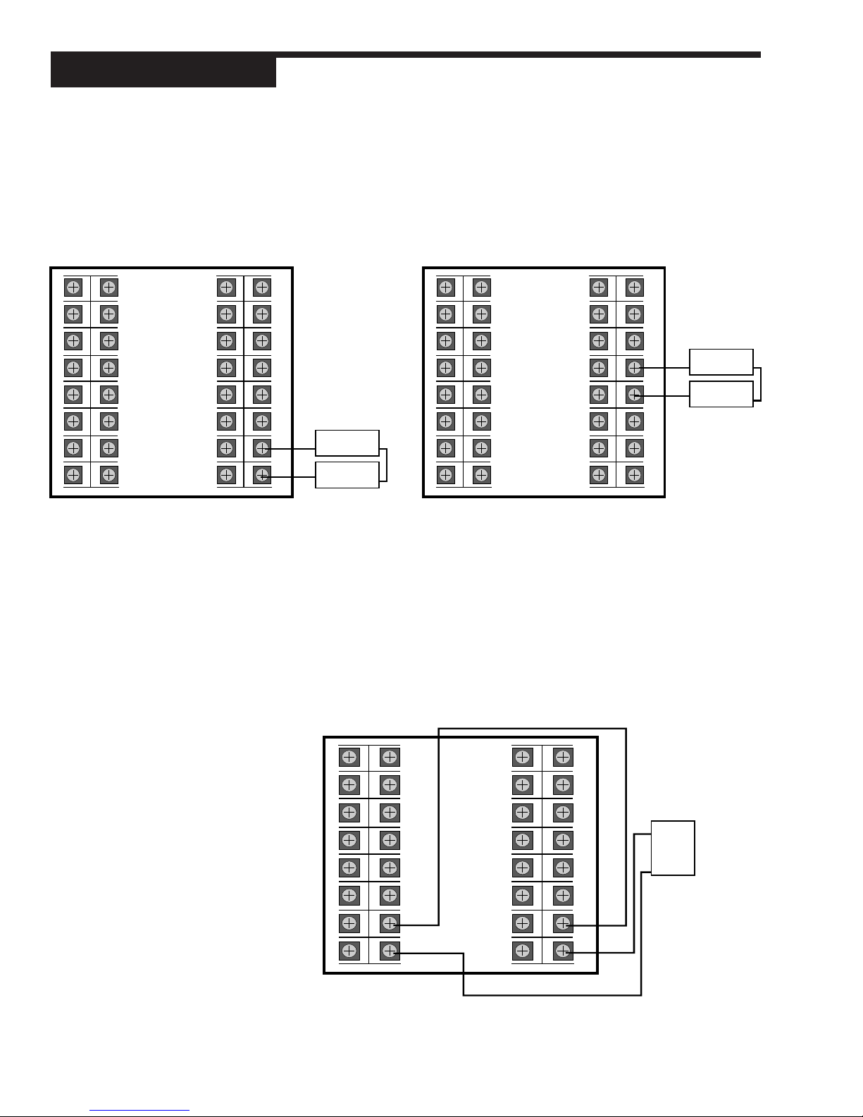
Output Modules
Output modules are used for control, alarms and retransmission (the wiring is
the same). There are three digital types — Mechanical Relay, Solid State Relay
(Triac), DC Logic (SSR Drive) — and one Analog type (Milliamp).
To identify which modules (if any) are installed on your 555, compare the product order code in Chapter 1 against the code on top of your controller. If you
want to change the configuration of the modules, refer to Chapter 3.
Wire using the corresponding output terminals (examples show Output 1).
1. Mechanical Relay Output (Figure 4.11)
• Output 1 is always the Control output.
• Output Slots 1 and 2 together will allow for duplex flow pacing mode
control (again, only as time-proportioned outputs).
•“Staging” outputs is not allowed.
• Output Slots 2, 3 and/or 4 can be used for alarms (up to two). However, Output 2 is not available for alarms when using “duplex” control (i.e., duplex flow pacing, staging, or slidewire).
25
26
27
28
29
Figure 4.11
Mechanical Relay Output
Wiring
18 Chapter 4 555 User's Manual
Output 1 uses terminals 3 & 4
Output 2 uses terminals 5 & 6
Output 3 uses terminals 7 & 4
Output 4 uses terminals 15 & 16
Line Power
Load
Recommend use of
both MOV and snubber
OUT 1–
OUT 1+
OUT 2–
OUT 2+
OUT 3–
OUT 3+
1
2
3
4
5
6
7
8
9
10
11
12
13
14
15
16
OUT 4–
OUT 4+
17
18
19
20
21
22
23
25
26
27
28
29
30
31
24 32
Screws must be tight to ensure electrical connection
Page 24
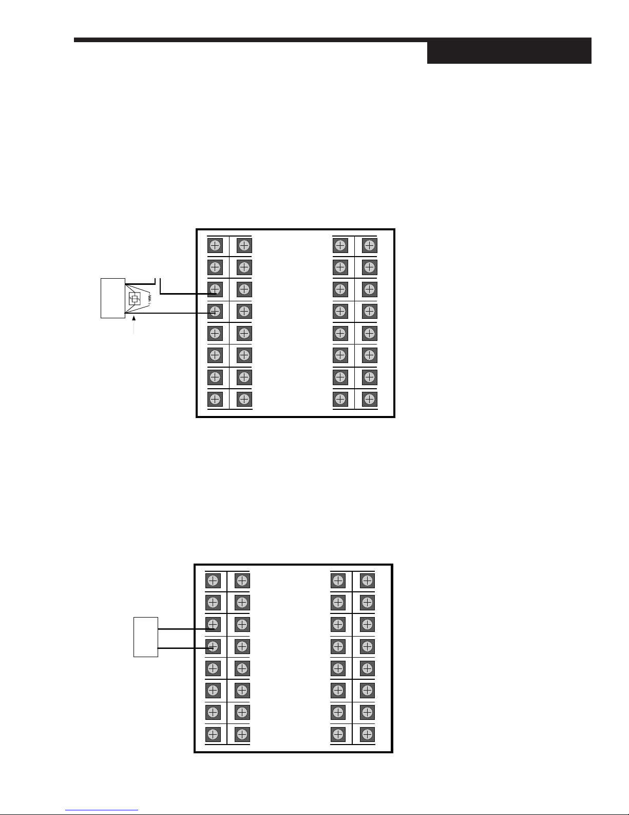
2. Solid State Relay (Triac) Output (Figure 4.12)
• Output 1 is always the Control output.
• Output Slots 1 and 2 together will allow for duplex flow pacing mode
control (again, only as time-proportioned outputs).
•“Staging” outputs is not allowed.
• Output Slots 2, 3 and/or 4 can be used for alarms (up to two); however, Output 2 is not available for alarms when using “duplex” control (i.e., duplex flow pacing, staging, or slidewire).
Output 1 uses terminals 3 & 4
Output 2 uses terminals 5 & 6
Output 3 uses terminals 7 & 4
Output 4 uses terminals 15 & 16
Line Power
–
Load
+
Recommend use of
both MOV and snubber
OUT 1–
OUT 1+
OUT 2–
OUT 2+
1
2
3
4
5
6
9
10
11
12
13
14
17
18
19
20
21
22
25
26
27
28
29
30
Installation
Figure 4.12
Solid State Relay Output Wiring
OUT 3–
7
OUT 3+
8
Screws must be tight to ensure electrical connection
15
16
OUT 4–
OUT 4+
23
24 32
3. DC Logic (SSR Drive) Output (Figure 4.13)
• Output 1 is always the Control output.
• Output Slots 1 and 2 together will allow for duplex flow pacing mode
control (again, only as time-proportioned outputs).
•“Staging” outputs is not allowed.
• Output Slots 2, 3 and/or 4 can be used for alarms (up to two); however, Output 2 is not available for alarms when using “duplex” control (i.e., duplex flow pacing, staging, or slidewire).
Output 1 uses terminals 3 & 4
Output 2 uses terminals 5 & 6
Output 3 uses terminals 7 & 4
Output 4 uses terminals 15 & 16
–
Load
+
OUT 1–
OUT 1+
OUT 2–
1
2
3
4
5
9
10
11
12
13
17
18
19
20
21
31
25
26
27
28
29
Figure 4.13
DC Logic Output and Milliamp
Output Wiring
OUT 2+
6
OUT 3–
7
OUT 3+
8
Screws must be tight to ensure electrical connection
555 User's Manual Chapter 4 19
14
15
16
OUT 4–
OUT 4+
22
23
30
31
24 32
Page 25
Installation
4. Milliamp (analog) Output (Figure 4.13)
• Output 1 is always the Control output.
• Output Slots 1 and 2 together allow for duplex flow pacing mode or
output “staging.”
• Output Slots 2, 3 and/or 4 can be used for retransmission (up to two).
However, Output 2 is not available when using duplex flow pacing,
staging or slidewire control.
5. Loop Power
• Any unused output slot (except for Output 1) may be used to hold a
loop power module, when needed to supply voltage for a transducer.
• Output 1 is always the Control output.
• Refer to Figure 4.7 for a diagram of Loop Power.
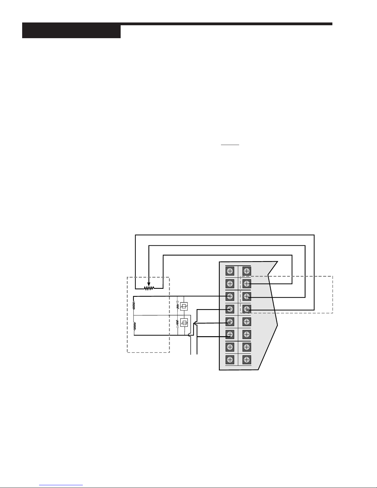
6. Position Proportioning Output (with Slidewire Feedback)
• Output Slots 1 and 2 with mechanical or solid state relay modules,
plus the slidewire option, will allow for electrical control valve actuators (motorized CCW/CW) to operate as the control output (see Figure 4.14).
Figure 4.14
Position Proportioning Output with
Slidewire Feedback Terminals
CW
Slidewire Wiper 0–1050
CCW
1
2
CCW
3
CCW
Winding
CW
Winding
ELECTRIC MOTOR
ACTUATOR
Actuator Supply Current
Screws must be tight to ensure electrical connection
COM
CW
COM
4
5
6
7
8
9
10
11
12
13
14
15
16
CCW
Slidewire Wiper
CW
ELECTRIC
ACTUATOR OUTPUT
20 Chapter 4 555 User's Manual
Page 26
Remote Setpoint
If you have the remote setpoint option, use terminals 13 and 14 to connect your
remote setpoint signal (Figure 4.15).
1
2
9
10
17
18
25
26
–
RSP
Source
+
Installation
Figure 4.15
Remote Setpoint Terminals
3
4
5
6
7
8
Screws must be tight to ensure electrical connection
11
12
13
14
15
16
RSP–
RSP+
19
20
21
22
23
27
28
29
30
31
24 32
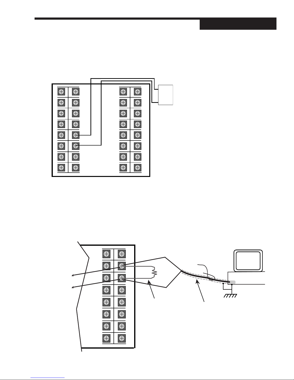
Serial Communications
If you have this option, use terminals 26 and 27 as shown in Figure 4.16.
A twisted shielded pair of wires should be used to interconnect the host and
field units. Belden #9414 foil shield or #8441 braid shield 22-gauge wire are
acceptable for most applications. The foil shielded wire has superior noise
rejection characteristics. The braid shielded wire has more flexibility. The
17
18
To Comm – terminal
of next device
To Comm + terminal
of next device
19
20
21
22
23
24 32
Screws must be tight to ensure electrical connection
555 User's Manual Chapter 4 21
25
26
27
28
29
30
31
RS485–
RS485+
Use a 60 to 100 ohm
terminating resistor
connected to the two
data terminals of the
final device on the line
Comm –
Twisted, shielded
Comm +
This shield needs to be connected continuously, but only tied to one
ground at the host. Failure to follow these proper wiring practices
could result in transmission errors and other communications
problems.
Figure 4.16
Serial Communications Terminals
PC or
other
RS-485
port
host
Page 27

Installation
maximum recommended length of the RS-485 line is 4000 feet. Termination resistors are required at the host and the last device on the line. Some
RS-485 cards/converters already have a terminating resistor. Use a
RS-232/RS-485 converter, Part #500-485. The communication protocol is
asynchronous bidirectional half-duplex, therefore the leads are labeled
Comm + and Comm–.
22 Chapter 4 555 User's Manual
Page 28
CHAPTER 5
SOFTW ARE CONFIGURATION
The software configuration menus of the 555 contain user-selected variables that
define the action of the controller. Read through this section before making any
parameter adjustments to your controller.
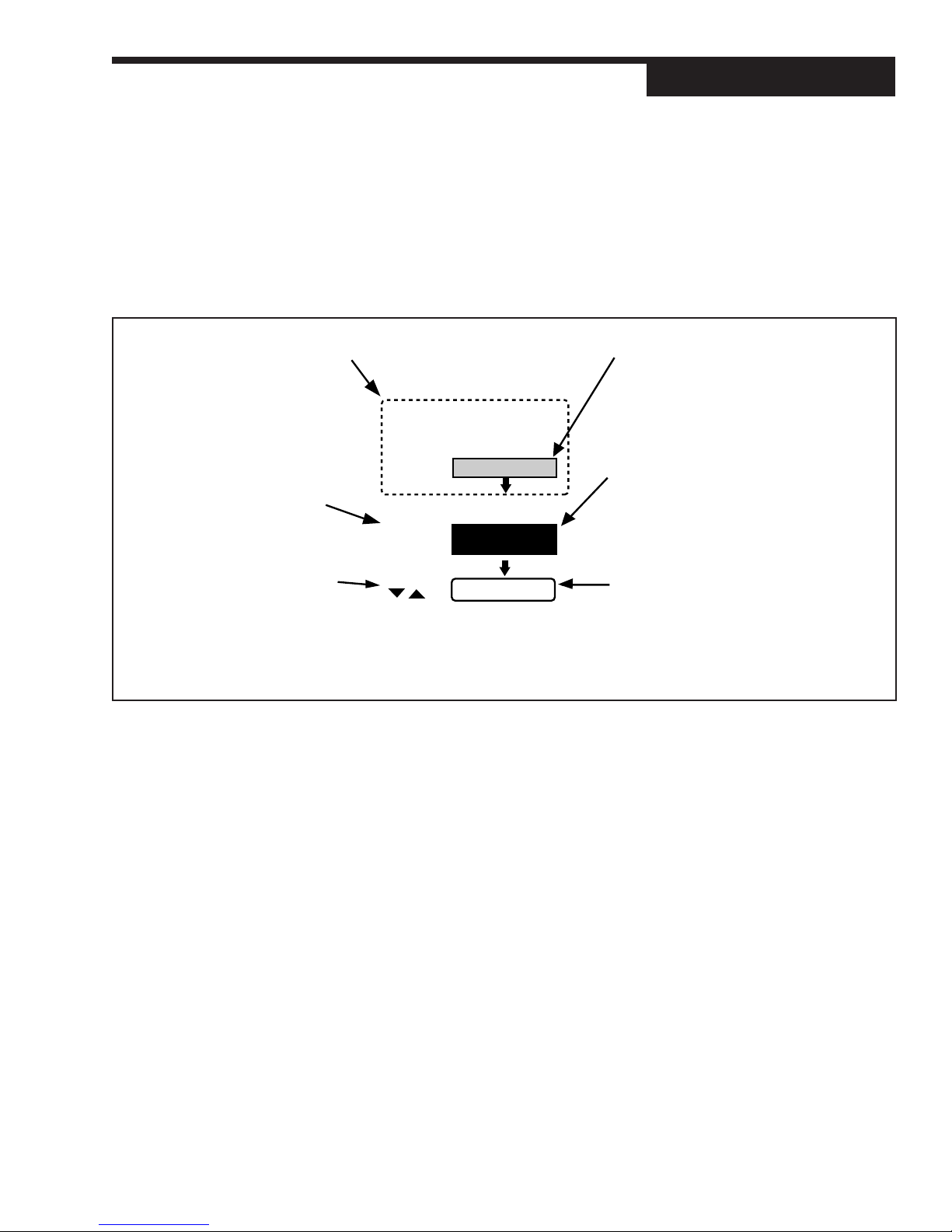
Software Configuration
Figure 5.1
Menus, Parameters and Values
When initially setting up the
controller, cycle through all the
parameters in each Menu.
Press the MENU+FAST to
advance to the next Menu.
Press MENU to advance to the
next parameter (this also sets the
value for the current parameter.
Use arrow keys to selects a value).
press:
MENU/FAST
CONFIG.
press:
MENU
INDICATOR
Use the arrows keys to enter
numerical values, and/or move
through the selection group.
press:
NONE
press MENU/FAST
Go to next Menu Block:
MENUS
In Set Up mode, there are 13 sets of options that control different aspects of 555
operation; in Tuning mode, there is one. Each set of options is called a menu. As
you traverse the two modes, the menu names appear in the 2nd display.
CONFIG Mode selection and input/output hardware assignments
CONTROL Control options
FLOW INPT. Flow data input (PV2) options
CUST. LINR. Linearization curve options for PV2 input.
RSDL. INPT. Residual Cl2 data input (PV1) options
SETPOINT Controller setpoint options
REM. INPUT Remote Setpoint input options
OUTPUT Output options
RETRANS. Retransmission output options
ALARMS Alarm options
POWER-UP Power Up values configuration
SECURITY Security functions
SER.COMM. Serial Communications options (requires comm. board)
and
TUNING Tuning parameters configuration
This is a Menu.
Its name will show in the 2nd display.
This is a Parameter.
Its names show in the 3nd display.
In this manual, when the appearance
of a parameter is dependent upon
other hardware/software options, the
background is black. When the
appearance of a paramter is dependent
on those options,the background is
white.
This is a Value.
The numbers/values that correspond to
your particular hardware/software
options will show in the 3rd display.
The graphics in this chapter show the
default (factory)setting.
IMPORTANT!!
All software changes occur in real time;
always perform set up functions under
Manual operation.
555 User's Manual Chapter 5 23
Page 29
Software Configuration
PARAMETERS
Independent
Parameter
CONFIGURE
UNLOCKED
Figure 5.2
Independent vs. Dependent
Parameters
NOTE:
Changing the value of one parameter
may affect the value or status of another.
Dependent
Parameter
RSP TYPE
(D)
MANUAL to switch
between automatic and
manual operating controls
DISPLAY or SET PT
Within each menu are parameters for particular control functions. You select
values for each parameter depending on the specific application. Use the MENU
key to access parameters for a particular menu; the parameter name will replace the menu name in the 2nd display, and the parameter value will show in
the 3rd display.
This chapter outlines all the available parameters for the 555. Some parameters
are independent of any special configuration you apply, and others are depen-
dent on the individual configuration. This manual displays these two types of
parameters differently; refer to Figure 5.2. A special feature of the 555, called
Smart Menus, determines the correct parameters to display for your configu-
ration, so not all the listed parameters will appear.
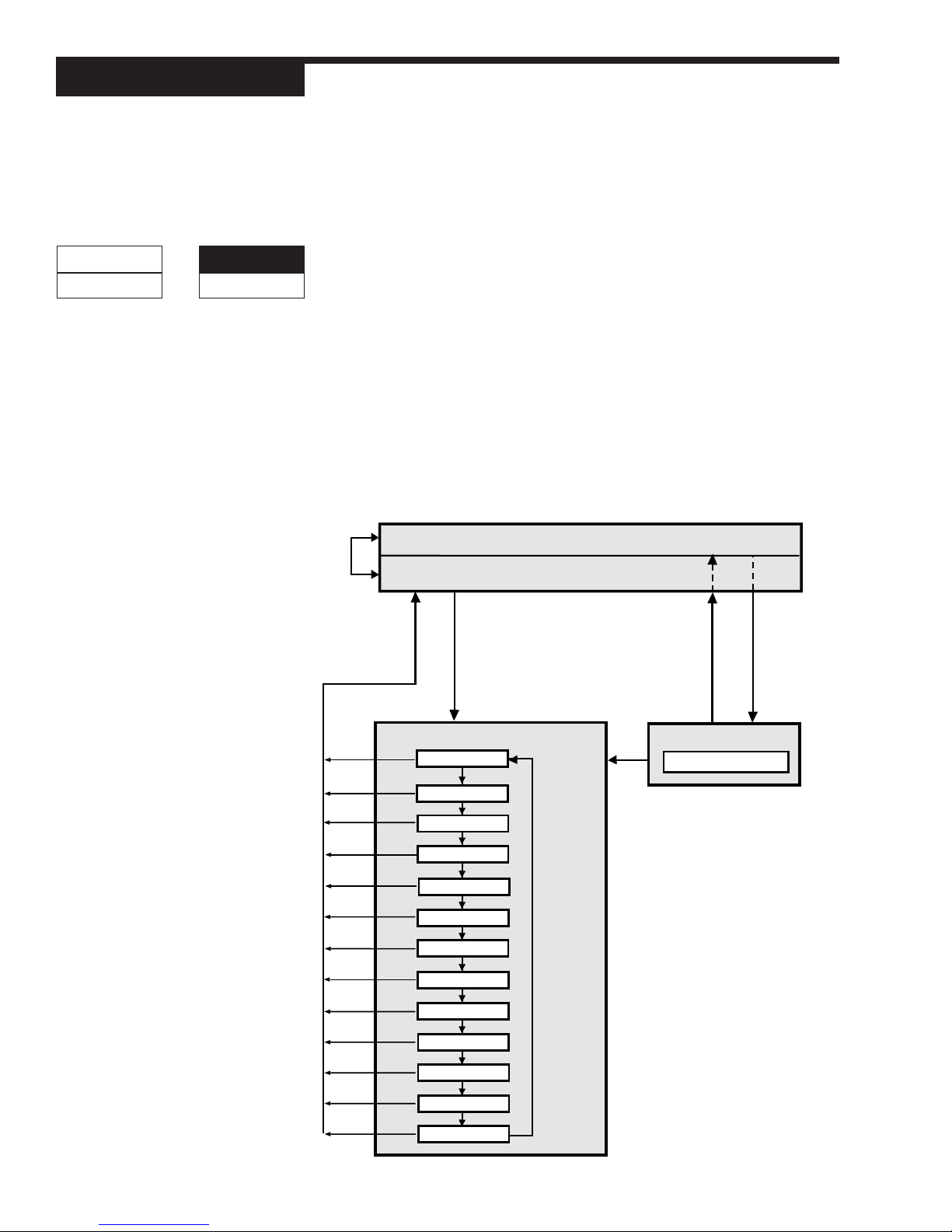
CONFIGURA TION AND OPERATION
Figure 5.3 shows the relationships among the different modes of the 555 and
the configuration menus:
AUTOMATIC control
MANUAL control
DISPLAY or SET PT
to return to manual
operating control
to restore
operating display
FAST + MENU
to access set up menus
MENU
to access
tuning menu
Figure 5.3
Operation and Configuration Flowchart
13 set up menus
CONFIG.
CONTROL
FLOW INPT.
CUST.LINR.
RSDL. INPT.
SETPOINT
REM. INPUT
OUTPUT
RETRANS.
ALARMS
POWER-UP
SECURITY
SER.COMM.
FAST
+
MENU
to move
from menu
to menu
FAST + MENU
to access
set up menus
1 tuning menu
TUNING
24 Chapter 5 555 User's Manual
Page 30

• Set Up menus can only be accessed from manual control. To transfer the
555 from automatic to manual control, press MANUAL.
• To access the set up menus, press FAST+MENU.
• To advance to the next menu, press FAST+MENU.
• Tuning mode (and the TUNING menu) can be accessed from either auto-
matic or manual control. To access the tuning menu, press MENU .
• To access the parameters for a particular menu, press MENU.
▲▲
• To select a parameter value, use
next parameter, or FAST+MENU to advance to the next menu.
• To return controller to manual control, press DISPLAY or SET PT.
• To transfer the controller from manual to automatic control when setting up
bumpless transfer dosage values, press FAST+MANUAL.
A key to these functions appears at the bottom of every page in the menu section
of this chapter.
▼▼
▲ and
▼. Press MENU to advance to the
▲▲
▼▼
WHERE T O GO NEXT
• For information about all the software menus and parameters, continue reading
this chapter. Refer to Appendix D for a quick-reference flowchart of all menus
and parameters.
• For information about the installed options on your 555, look at the product
label on top of the controller, and compare it to the order code in Chapter 1.
• To alter the output module and jumper configuration of your controller, see
Chapter 3.
• To mount your controller and configure the wiring of the 555 for inputs and
outputs, see Chapter 4.
• To set up the 555 control modes, and other applications, see Chapter 6.
Software Configuration
555 User's Manual Chapter 5 25
Page 31

Software Configuration
26 Chapter 5 555 User's Manual
Page 32

SOFTW ARE MENU AND P ARAMETERS
Software Configuration
CONFIG.
1. CTRL. MODE
Selects the main operating mode of the controller.
• FLOW PACE
• RESIDUAL
D COMPOUND
• DECHLOR
2. OUT. MODE
Selects the control output mode of the controller.
D STANDARD Fixed value if different modules in slots 1 and
2, slot 2 is empty, or 2 digital outputs with no
slidewire option
• STAGED Only available if analog modules in slots 1 and 2.
• SLIDEWIRE Only available if digital modules in slots 1 and
2 and slidewire option installed)
• DUAL OUT. Only available if 2 analog or 2 digital modules
in slots 1 and 2 with flow pacing mode
3. LINE FREQ.
Defines the AC line frequency, so that the input sampling rate will be optimized for common mode noise rejection.
D 60 HZ.
• 50 HZ.
CONFIG
CTRL. MODE
COMPOUND
OUT . MODE
STANDARD
LINE FREQ.
60 HZ.
4. OUTPUT 2
Selects use for an existing output in slot 2 (not for control or loop power).
D OFF
• ALM.RLY.: ON (digital only)
• ALM.RLY.: OFF (digital only)
• RETRANS. (analog only)
• COMM. ONLY
OUTPUT 2
OFF
5. OUTPUT 3
Selects use for an existing output in slot 3 (not for control or loop power).
D OFF
• ALM.RLY.: ON (digital only)
• ALM.RLY.: OFF (digital only)
• RETRANS. (analog only)
• COMM. ONLY
Access Set Up Return to Operation Next menu Next parameter Next value Access Tuning Return to Operation
+
FAST MENU
555 User's Manual Chapter 5 27
DISPLAY
+
FAST MENU
MENU
▲▲
▲
▲▲
▼▼
▼
▼▼
OUTPUT 3
OFF
MENU
DISPLAY
Page 33

Software Configuration
6. OUTPUT 4
OUTPUT 4
OFF
7. ANLG.RNG.:1
aNLG.RNG.: 1
4-20 MA
Selects use for an existing output in slot 4 (not for control or loop power).
D OFF
• ALM.RLY.: ON (digital only)
• ALM.RLY.: OFF (digital only)
• RETRANS. (analog only)
• COMM. ONLY
Selects the range of operation for an existing mA output in slot 1.
• 0 – 20mA
D 4 – 20mA
ANLG.RNG.: 2
4-20 MA
ANLG.RNG.: 3
4-20 MA
ANLG.RNG.: 4
4-20 MA
CONT A CT 1
MANU A L
8. ANLG.RNG.: 2
Selects the range of operation for an existing mA output in slot 2.
• 0 – 20mA
D 4 – 20mA
9. ANLG.RNG.: 3
Selects the range of operation for an existing mA output in slot 3.
• 0 – 20mA
D 4 – 20mA
10. ANLG.RNG.: 4
Selects the range of operation for an existing mA output in slot 4.
• 0 – 20mA
D 4 – 20mA
11. CONTACT 1
Selects the use for the existing digital input 1.
• REM. INPUT
D MANUAL
• 2ND. SETPT.
• 2ND. INT.
• ALARM ACK.
• INT. INHBT.
• LOCK MAN.
• STANDBY
• LO VACUUM
• HI VACUUM
• UP KEY
• DOWN KEY
• DISP. KEY
• MENU KEY
• FAST KEY
• COMM. ONLY
Access Set Up Return to Operation Next menu Next parameter Next value Access Tuning Return to Operation
+
FAST MENU
28 Chapter 5 555 User's Manual
DISPLAY
FAST MENU
+
MENU
▲
▲▲
▲▲
▼▼
▼
▼▼
MENU
DISPLAY
Page 34

12. CONTACT 2
Selects the use for the existing digital input 2.
D REM. INPUT
• MANUAL
• 2ND. SETPT.
• 2ND. INT.
• ALARM ACK.
• INT. INHBT.
• LOCK MAN.
• STANDBY
• LO VACUUM
• HI VACUUM
• UP KEY
• DOWN KEY
• DISP. KEY
• MENU KEY
• FAST KEY
• COMM. ONLY
Software Configuration
CONT A CT 2
REM. INPUT
13. CONTACT 3
Selects the use for the existing digital input 3.
• REM. INPUT
• MANUAL
D 2ND. SETPT.
• 2ND. INT.
• ALARM ACK.
• INT. INHBT.
• LOCK MAN.
• STANDBY
• LO VACUUM
• HI VACUUM
• UP KEY
• DOWN KEY
• DISP. KEY
• MENU KEY
• FAST KEY
• COMM. ONLY.
CONT A CT 3
2ND.SETPT.
Access Set Up Return to Operation Next menu Next parameter Next value Access Tuning Return to Operation
+
FAST MENU
555 User's Manual Chapter 5 29
DISPLAY
+
FAST MENU
MENU
▲▲
▲
▲▲
▼▼
▼
▼▼
MENU
DISPLAY
Page 35

Software Configuration
14. CONTACT 4
CONT A CT 4
2ND. INT .
Selects the use for the existing digital input 4.
• REM. INPUT
• MANUAL
• 2ND. SETPT.
D 2ND. INT.
• ALARM ACK
• INT. INHBT.
• LOCK MAN.
• STANDBY
• LO VACUUM
• HI VACUUM
• UP KEY
• DOWN KEY
• DISP. KEY
• MENU KEY
• FAST KEY
• COMM. ONLY
CONT A CT 5
ALARM. A CK.
REMOTE IN.
OFF
15. CONTACT 5
Selects the use for the existing digital input 5.
• REM. INPUT
• MANUAL
• 2ND. SETPT.
• 2ND. INT.
D ALARM ACK.
• INT. INHBT.
• LOCK MAN.
• STANDBY
• LO VACUUM
• HI VACUUM
• UP KEY
• DOWN KEY
• DISP. KEY
• MENU KEY
• FAST KEY
• COMM. ONLY
16. REMOTE IN.
Defines the value of the remote setpoint feature.
D OFF
• SETPOINT
• CL2 DOSE
• SO2 DOSE
Access Set Up Return to Operation Next menu Next parameter Next value Access Tuning Return to Operation
+
FAST MENU
30 Chapter 5 555 User's Manual
DISPLAY
FAST MENU
+
MENU
▲
▲▲
▲▲
▼▼
▼
▼▼
MENU
DISPLAY
Page 36

Software Configuration
CONTROL
Available only for Residual or Compound Loop Mode.
1. FIXED LAG
Sets the fixed lag term used for computing the total lag.
R 0 to 14400 seconds
D0
2. VARBL. LAG
(Compound Loop mode)
Sets the variable lag term used for computing the total lag.
R 0 to 14400 seconds
D0
3. MAX. LAG
(Compound Loop mode)
Sets the maximum limit for the total lag calculation.
R 0 to 14400 seconds
D 14400
4. MIN. TRIM
(Compound Loop mode)
Sets the minimum amount of correction that can be applied to the current flow
pacing output level.
R –100 to 100%
D –100%
CONTROL
FIXED LA G
0
V ARBL. L AG
0
MAX. LA G
14400
MIN. TRIM
-100%
5. MAX. TRIM
(Compound Loop mode)
Sets the maximum amount of correction that can be applied to the current flow
pacing output level.
R –100 to 100%
D 100%.
MAX. TRIM
100%
6. FLOW ONLY
(Compound Loop mode)
Determines whether to allow flow pacing only control or remain under
automatic control if the residual signal is lost (see RSDL REST. in the
RSDL.INPT. menu).
D DISABLED
• ENABLED
Access Set Up Return to Operation Next menu Next parameter Next value Access Tuning Return to Operation
+
FAST MENU
555 User's Manual Chapter 5 31
DISPLAY
+
FAST MENU
MENU
▲▲
▲
▲▲
▼▼
▼
▼▼
FLO W ONL Y
DISABLED
MENU
DISPLAY
Page 37

Software Configuration
RSDL. ONLY
disabled
FLO W INPT .
PV TYPE
4-20 mA
7. RSDL. ONLY
(Compound Loop mode)
Determines whether to allow residual only control (i.e., remain under auto-
matic control) if the flow signal is lost (see FLOW REST. in the FLOW INPT.
menu).
D DISABLED
• ENABLED
FLO W INPT .
Available only when a flow signal is used (Flow Pacing, Compound Loop or
Dechlorination Mode).
1. PV TYPE
Selects the type of PV being used for the flow input.
If jumper is set to volts:
D 1 – 5V
• 0 – 5V
• 0 – 100mV
• 0 – 60mV
• 0 – 30mV
• 0 – 10mV
• ± 25mV
If jumper is set to mA:
D 4 – 20mA
• 0 – 20mA
DECIMAL
XXXXX
LINEARIZE
NORMAL
LO W RANGE
0
Access Set Up Return to Operation Next menu Next parameter Next value Access Tuning Return to Operation
+
FAST MENU
32 Chapter 5 555 User's Manual
DISPLAY
2. DECIMAL
Selects position of the decimal point in the engineering units display of flow.
D XXXXX
• XXXX.X
• XXX.XX
• XX.XXX
• X.XXXX
3. LINEARIZE
Selects the type of linearization used for the flow input.
D NORMAL
• SQR. ROOT
• CUSTOM
4. LOW RANGE
Sets the value in engineering units corresponding to the low flow input value.
R –9999 to 99999
D0
+
FAST MENU
MENU
▲
▲▲
▲▲
▼▼
▼
▼▼
MENU
DISPLAY
Page 38

5. HI RANGE
Sets the value in engineering units corresponding to the high flow input value.
R –9999 to 99999
D 1000
6. FILTER
Sets the amount of filtering to be used for the flow input.
R 0 to 120 seconds
D0
7. PV OFFSET
Sets a constant offset to be applied to the flow input.
R –9999 to 99999
D0
8. PV GAIN
Sets a constant gain to be applied to the flow input.
R 0.100 to 10.000
D 1.000
9. FLOW BRK.
Defines percentage of (first) output upon switching to Manual control due to a
flow signal break signal.
R -5% to 105%
D0%
10. FLOW BRK.2
(Dual Flow Pacing mode)
Defines percentage of second output upon switching to Manual control due to
a flow signal break signal.
R -5% to 105%
D0%
Software Configuration
HI RANGE
1000
FILTER
0
PV OFFSET
0
PV GAIN
1.000
FLO W BRK.
0%
FLO W BRK.2
0%
11. FLOW REST.
(Flow Pacing mode, Dechlorination mode, and Compound Loop mode with
Residual Only control disabled)
Defines type of control mode after flow signal is restored.
D LAST MODE
• MANUAL
• AUTOMATIC
Access Set Up Return to Operation Next menu Next parameter Next value Access Tuning Return to Operation
+
FAST MENU
555 User's Manual Chapter 5 33
DISPLAY
+
FAST MENU
MENU
▲▲
▲
▲▲
▼▼
▼
▼▼
FLO W REST.
LAST MODE
MENU
DISPLAY
Page 39

Software Configuration
CUST.LINR.
1ST . INPUT
LO W RANGE
1ST . PV
0
XTH. INPUT
LO W RANGE
XTH. PV
0
CUST.LINR.
Available only if a flow signal is used (Flow Pacing, Compound Loop or Dechlorina-
tion mode) with LINEARIZE set to CUSTOM.
Defines a custom linearization curve for the Flow input (PV2). Points 1 and 15 are
fixed to the low and high end of the input range (respectively) and only require you
to set a corresponding PV value. Points 1 through 14 (the X points) require you to
set both the input and the PV.
You do not have to use all 15 points. Whenever the Xth INPUT becomes the high
end of the range, that will be the last point in the linearization table.
Refer to Chapter 6 for more details.
1. 1st. INPUT
Sets the flow input value for Point 1.
R LOW RANGE to HIGH RANGE based on FLOW PV TYPE
D LOW RANGE
2. 1st. PV
Sets the engineering units value for Point 1.
R –9999 to 99999
D0
3. Xth. INPUT
Sets the flow input value for Point X (X = 2 to 14).
R LOW RANGE to HIGH RANGE based on FLOW PV TYPE
D LOW RANGE
4. Xth. PV
Sets the engineering units value for Point X (X = 2 to 14).
R –9999 to 99999
D0
15TH. INPUT
LO W RANGE
15TH. PV
0
Access Set Up Return to Operation Next menu Next parameter Next value Access Tuning Return to Operation
+
FAST MENU
34 Chapter 5 555 User's Manual
DISPLAY
FAST MENU
29. 15th. INPUT
Sets the flow input value for Point 15.
R LOW RANGE to HIGH RANGE based on FLOW PV TYPE
D LOW RANGE
30. 15th. PV
Sets the engineering units value for Point 15.
R –9999 to 99999
D0
+
MENU
▲
▲▲
▲▲
▼▼
▼
▼▼
MENU
DISPLAY
Page 40

Software Configuration
RSDL. INPT.
Available only if a residual chlorine signal is used (Compound Loop or Dechlorination mode).
1. PV TYPE
Selects the type of PV being used for the residual chlorine input.
If jumper set to volts
D 1 – 5V
• 0 – 5V
• 0 – 100mV
• 0 – 60mV
• 0 – 30mV
• 0 – 10mV
• ± 25mV
If jumper set to mA:
D 4 – 20mA
• 0 – 20mA
2. DECIMAL
Selects the position of the decimal point in the engineering units display of residual value.
D XXXXX
• XXXX.X
• XXX.XX
• XX.XXX
• X.XXXX
RSDL. INPT.
PV TYPE
4-20 mA
DECIMAL
XXXXX
3. LOW RANGE
Sets the value in engineering units corresponding to the low residual input
value.
R –9999 to 99999
D0
LO W RANGE
0
4. HI RANGE
Sets the value in engineering units corresponding to the high residual input
value.
R –9999 to 99999
D 1000
HI RANGE
1000
5. FILTER
Sets the amount of filtering to be used for the residual input.
R 0 to 120 seconds
D0
Access Set Up Return to Operation Next menu Next parameter Next value Access Tuning Return to Operation
+
FAST MENU
555 User's Manual Chapter 5 35
DISPLAY
+
FAST MENU
MENU
▲▲
▲
▲▲
▼▼
▼
▼▼
FILTER
0
MENU
DISPLAY
Page 41

Software Configuration
PV OFFSET
0
PV GAIN
1.000
RSDL. BRK.
0%
RSDL. REST .
LAST MODE
SETPOINT
6. PV OFFSET
Sets a constant offset to be applied to the residual input.
R –9999 to 99999
D0
7. PV GAIN
Sets a constant gain to be applied to the residual input.
R 0.100 to 10.000
D 1.000
8. RSDL. BRK.
Defines output percentage upon switching to Manual control due to a break in
the residual signal.
R -5% to 105%
D0%
9. RSDL. REST.
(Residual mode, Dechlorination mode, and Compound Loop mode with Flowonly control disabled).
Defines control mode upon restoration of residual signal.
D LAST MODE
• MANUAL
• AUTOMATIC
SETPOINT
SP LO W
Available only for Residual or Compound Loop mode.
1. SP LOW
0
SP HIGH
1000
Sets the value in engineering units corresponding to the lowest SP value allowed.
R –9999 to 99999
D0
2. SP HIGH
Sets the value in engineering units corresponding to the highest SP value allowed.
R –9999 to 99999
D 1000
3. SP RAMP
Turns SP ramping off, or defines the SP ramping rate in engineering units per
SP RAMP
OFF
Access Set Up Return to Operation Next menu Next parameter Next value Access Tuning Return to Operation
+
FAST MENU
DISPLAY
FAST MENU
hour (e.g., a value of 3600 translates to 1 SP step increment every second).
R 1 to 99999
D OFF
+
MENU
▲
▲▲
▲▲
▼▼
▼
▼▼
MENU
DISPLAY
36 Chapter 5 555 User's Manual
Page 42

Software Configuration
REM. INPUT
Availble only if the remote input (REMOTE IN.) is enabled.
1. TYPE V/mA
Selects the type/value for the Remote Input.
D 1 – 5 / 4 – 20 1 – 5 V, 4 – 20mA
• 0 – 5 / 0 – 20 0 – 5V, 0 – 20mA
2. LOW RANGE
Sets the value in engineering units corresponding to the low remote input
value.
For SP:
R –9999 to 99999
D0
For Dose:
R 0.0% to 400.0%
D 0.0%
3. HI RANGE
Sets the value in engineering units corresponding to the high remote input
value.
For SP:
R –9999 to 99999
D 1000
For Dose:
R 0.0% to 400.0%
D 100.0%
REM. INPUT
TYPE V/MA
1-5/4-20
LOW RANGE
0
HI RANGE
1000
4. RATIO
Sets the ratio (a constant gain) applied to the remote input.
R –99.99 to 99.99
D 1.00
5. BIAS
Sets the bias (a constant offset) applied to the remote input.
For SP:
R –9999 to 99999
D0
For Dose:
R –400.0% to 400.0%
D 0.0%
Access Set Up Return to Operation Next menu Next parameter Next value Access Tuning Return to Operation
+
FAST MENU
555 User's Manual Chapter 5 37
DISPLAY
+
FAST MENU
MENU
▲▲
▲
▲▲
▼▼
▼
▼▼
RATIO
1.00
BIAS
0
MENU
DISPLAY
Page 43

Software Configuration
TRACKING
NO
RESTORE
LOCAL
OUTPUT
MIN. OUT.
0%
MAX. OUT .
100%
6. TRACKING
Determines whether or not to keep the remote input value if the signal is lost.
Otherwise, the controller automatically uses a local value.
• YES
DNO
7. RESTORE
Defines which value to use once the remote input signal is restored.
D LOCAL
• REMOTE
OUTPUT
1. MIN. OUT.
Selects the lowest value for the output under automatic control (NOTE: The
555 will not limit the output under manual control).
R 0 to 100 %
D0%
2. MAX. OUT.
Selects the highest value for the output under automatic control (NOTE: The
555 will not limit the output under manual control).
R 0 to 100%
D 100%
3. MIN. OUT2
MIN.OUT2
0%
(Dual Flow Pacing mode)
Selects the lowest value for the second output under automatic control.
(NOTE: The 555 will not limit the output under manual control.)
R 0 to 100 %
D0%
4. MAX. OUT2
(Dual Flow Pacing mode)
MAX.OUT2
100%
Selects the highest value for the second output under automatic control.
(NOTE: The 555 will not limit the output under manual control).
R 0 to 100%
D 100%
5. CYCLE TM.:1
Selects the time base for output 1, when time-proportioning a digital output.
CYCLE TM.:1
15
Access Set Up Return to Operation Next menu Next parameter Next value Access Tuning Return to Operation
+
FAST MENU
DISPLAY
FAST MENU
Appears only when a digital output in slot 1 is being used for a control (except
when using slidewire).
R 0.3 to 2.0 (by tenths), 3 to 120 seconds (by ones)
D 15 seconds
+
MENU
▲
▲▲
▲▲
▼▼
▼
▼▼
MENU
DISPLAY
38 Chapter 5 555 User's Manual
Page 44

Software Configuration
6. CYCLE TM.:2
Selects the time base for output 2, when time-proportioning a digital output.
Appears only when a digital output in slot 2 is being used for a control (except
when using slidewire).
R 0.3 to 2.0 (by tenths), 3 to 120 seconds (by ones)
D 15 seconds
7. DIG.IN.1:OUT.
Selects the designated output for an existing manual, locked manual,
standby, low vacuum, or high vacuum digital contact 1.
D LAST OUT.
R –5 to 105%
8. DIG.IN.2:OUT.
Selects the designated output for an existing manual, locked manual,
standby, low vacuum, or high vacuum digital contact 2.
D LAST OUT.
R –5 to 105%
9. DIG.IN.3:OUT.
Selects the designated output for an existing manual, locked manual,
standby, low vacuum, or high vacuum digital contact 3.
D LAST OUT.
R –5 to 105%
FLO W REST .
LAST MODE
DIG.IN.1:OUT.
LAST OUT .
DIG.IN.2:OUT.
LAST OUT .
DIG.IN.3:OUT.
LAST OUT .
10. DIG.IN.4:OUT.
Selects the designated output for an existing manual, locked manual,
standby, low vacuum, or high vacuum digital contact 4.
D LAST OUT.
R –5 to 105%
DIG.IN.4:OUT.
LAST OUT .
11. DIG.IN.5:OUT.
Selects the designated output for an existing manual, locked manual,
standby, low vacuum, or high vacuum digital contact 5.
D LAST OUT.
R –5 to 105%
DIG.IN.5:OUT.
LAST OUT .
12. DIG.IN.1:OUT2
(Dual Flow Pacing mode)
For existing properly configured contacts: Selects the designated second
output for a manual, locked manual, standby, low vacuum, or high vacuum
digital contact 1.
D LAST OUT.
R –5 to 105%
Access Set Up Return to Operation Next menu Next parameter Next value Access Tuning Return to Operation
+
FAST MENU
DISPLAY
+
FAST MENU
MENU
▲▲
▲
▲▲
▼▼
▼
▼▼
DIG.IN.1:OUT2
LAST OUT .
MENU
DISPLAY
555 User's Manual Chapter 5 39
Page 45

Software Configuration
DIG.IN.2:OUT2
LAST OUT .
DIG.IN.3:OUT2
LAST OUT .
DIG.IN.4:OUT2
LAST OUT .
13. DIG.IN.2:OUT2
(Dual Flow Pacing mode)
For existing properly configured contacts: Selects the designated second
output for a manual, locked manual, standby, low vacuum, or high vacuum
digital contact 2.
D LAST OUT.
R –5 to 105%
14. DIG.IN.3:OUT2
(Dual Flow Pacing mode)
For existing properly configured contacts: Selects the designated second
output for a manual, locked manual, standby, low vacuum, or high vacuum
digital contact 3.
D LAST OUT.
R –5 to 105%
15. DIG.IN.4:OUT2
(Dual Flow Pacing mode)
For existing properly configured contacts: Selects the designated second
output for a manual, locked manual, standby, low vacuum, or high vacuum
digital contact 4.
D LAST OUT.
R –5 to 105%
DIG.IN.5:OUT2
LAST OUT .
STAGE:OUT1
50%
STAGE:OUT2
50%
16. DIG.IN.5:OUT2
(Dual Flow Pacing mode)
For existing properly configured contacts: Selects the designated second
output for a manual, locked manual, standby, low vacuum, or high vacuum
digital contact 5.
D LAST OUT.
R –5 to 105%
17. STAGE:OUT1
When staging outputs, selects the value of the control output value at which
output 1 stops (100% for output 1).
R 1 to 100%
D 50%
18. STAGE:OUT2
When staging outputs, selects the value of the control output at which output
2 starts (at 0%). 100% control output = 100% on output 2.
R 0 to 99%
D 50%
Access Set Up Return to Operation Next menu Next parameter Next value Access Tuning Return to Operation
+
FAST MENU
40 Chapter 5 555 User's Manual
DISPLAY
FAST MENU
+
MENU
▲
▲▲
▲▲
▼▼
▼
▼▼
MENU
DISPLAY
Page 46

19. S/W RANGE
Sets the full range resistance of the slidewire being used.
R 1 to 1050 ohms
D 1000 ohms
Software Configuration
S/W RANGE
1000
20. S/W OPEN
Sets the slidewire position corresponding to “OPEN” (100% output value).
R 0 to current S/W RANGE value
D 1000 ohms
21. S/W CLOSE
Sets the slidewire position corresponding to “CLOSE” (0% output value).
R 0 to current S/W RANGE value
D 100 ohms
22. S/W D.BAND
Sets the value percentage of the deadband applied to slidewire control.
R 0.5 to 10.0% (in 0.5% increments)
D 2.0 %
23. S/W BREAK
Defines the action to take if the slidewire input is lost (while under automatic
control). For ON options, the corresponding relay is turned on (closed) and
stays that way throughout the break condition.
D OUTS. OFF same as last out
• OUT1 ON
• OUT2 ON
S/W OPEN
1000
S/W CLOSE
100
S/W D.BAND
2.0%
S/W BREAK
OUTS. OFF
RETRANS.
Requires outputs configured for retransmission. Up to two outputs are allowed for
retransmission. Any undefined choices will give “undefined” results (flat line).
RETRANS.
1. RET. TYPE: 2
Selects the type data retransmission for existing retransmission output 2.
D OUT
• FLOW
• RESIDUAL
• CL2 DOSE
• SO2 DOSE
• SETPOINT
• RAMP SP
Access Set Up Return to Operation Next menu Next parameter Next value Access Tuning Return to Operation
+
FAST MENU
555 User's Manual Chapter 5 41
DISPLAY
+
FAST MENU
MENU
▲▲
▲
▲▲
▼▼
▼
▼▼
RET. TYPE: 2
OUT
MENU
DISPLAY
Page 47

Software Configuration
RET . LO W: 2
0
RET . HIGH: 2
1000
RET. TYPE: 3
OUT
RET . LO W: 3
0
2. RET. LOW: 2
Sets the value in engineering units corresponding to the low retransmission
output value 2 (except for retransmission of output).
R –9999 to 99999
D0
3. RET. HIGH: 2
Sets the value in engineering units corresponding to the high retransmission
output value 2 (except for retransmission of output).
R –9999 to 99999
D 1000
4. RET. TYPE: 3
Selects the type data retransmission for existing retransmission output 3.
D OUT
• FLOW
• RESIDUAL
• CL2 DOSE
• SO2 DOSE
• SETPOINT
• RAMP SP
5. RET. LOW: 3
Sets the value in engineering units corresponding to the low retransmission
output value 3 (except for retransmission of output).
R –9999 to 99999
D0
6. RET. HIGH: 3
RET . HIGH: 3
1000
Sets the value in engineering units corresponding to the high retransmission
output value 3 (except for retransmission of output).
R –9999 to 99999
D 1000
7. RET. TYPE: 4
RET. TYPE: 4
OUT
Access Set Up Return to Operation Next menu Next parameter Next value Access Tuning Return to Operation
+
FAST MENU
42 Chapter 5 555 User's Manual
DISPLAY
FAST MENU
Selects the type data retransmission for existing retransmission output 4.
D OUT
• FLOW
• RESIDUAL
• CL2 DOSE
• SO2 DOSE
• SETPOINT
• RAMP SP
+
MENU
▲
▲▲
▲▲
▼▼
▼
▼▼
MENU
DISPLAY
Page 48

8. RET. LOW: 4
Sets the value in engineering units corresponding to the low retransmission
output value 4 (except for retransmission of output).
R –9999 to 99999
D0
9. RET. HIGH: 4
Sets the value in engineering units corresponding to the high retransmission
output value 4 (except for retransmission of output).
R –9999 to 99999
D 1000
Software Configuration
RET . LOW: 4
0
RET . HIGH: 4
1000
ALARMS
Note: All alarms may be assigned to the same output.
1. ALM.TYPE: 1
Selects the type for alarm 1.
D OFF
• HIGH ALRM.
• LOW ALARM
• MANUAL
• VACUUM
• BAND
• DEVIATION
• RATE
2. ALARM SRC: 1
For ALM.TYPE 1 = HIGH ALRM. or LOW ALARM, selects the alarm source.
D FLOW
• RESIDUAL
• CL2 DOSE
• SO2 DOSE
• SETPOINT
• RAMP SP
• DEVIATION
• OUTPUT
ALARMS
ALM.TYPE: 1
OFF
ALARM SRC: 1
FLO W
Access Set Up Return to Operation Next menu Next parameter Next value Access Tuning Return to Operation
+
FAST MENU
555 User's Manual Chapter 5 43
DISPLAY
+
FAST MENU
MENU
▲▲
▲
▲▲
▼▼
▼
▼▼
MENU
DISPLAY
Page 49

Software Configuration
3. ALARM SP: 1
ALARM SP . 1
0
4. DEADBAND: 1
DEADBAND: 1
D
Selects the setpoint for ALM.TYPE 1 = HIGH ALRM., LOW ALARM, BAND,
DEVIATION or RATE.
If ALARM SRC: 1 = FLOW, RESIDUAL, SETPOINT, RAMP or DEVIATION:
R –9999 to 99999
D0
If ALARM SRC: 1 = CL2 DOSE, SO2 DOSE, or OUTPUT:
R 0.0% to 400.0%
D0%
Selects the deadband.for ALM.TYPE 1 = HIGH ALRM., LOW ALARM,
BAND, DEVIATION or RATE,
If ALARM SRC: 1 = FLOW, RESIDUAL, SETPOINT, RAMP or DEVIATION:
R –1 to 99999
D2
If ALARM SRC: 1 = CL2 DOSE, SO2 DOSE, or OUTPUT:
R 0.0% to 400.0%
D 0.2%
ALM:1OUT.
NONE
LATCHING: 1
LATCH
ACK.: 1
ENABLED
POWER UP: 1
NORMAL
5. ALM.:1 OUT.
For an enabled ALM.TYPE 1, selects the physical output number.
D NONE
• ( of any outputs configured as alarms)
6. LATCHING: 1
For an enabled ALM.TYPE 1, enables or disables alarm latching.
D LATCH
• NO LATCH
7. ACK.: 1
For an enabled ALM.TYPE 1, enables or disables the ACK key.
D ENABLED
• DISABLED
8. POWER UP: 1
For an enabled ALM.TYPE 1, selects condition of the alarm upon power-up.
D NORMAL
• ALARM
• DELAYED
Access Set Up Return to Operation Next menu Next parameter Next value Access Tuning Return to Operation
+
FAST MENU
44 Chapter 5 555 User's Manual
DISPLAY
FAST MENU
+
MENU
▲
▲▲
▲▲
▼▼
▼
▼▼
MENU
DISPLAY
Page 50

9. MESSAGE: 1
For enabled ALM.TYPE 1 (except for type VACUUM), a 9-character user-defined message can be shown in the 3rd line display when the alarm is activated.
To use: Select a character with the FAST key (cursor will flash). Use
keys to modify. Selecting all blanks disables the alarm message.
D ALARM 1
10. ALM.TYPE: 2
Selects the type for alarm 2.
D OFF
• HIGH ALRM.
• LOW ALARM
• MANUAL
• VACUUM
• BAND
• DEVIATION
• RATE
▲▲
▲ and
▲▲
Software Configuration
MESSAGE: 1
LAST MODE
▼▼
▼
▼▼
ALM.TYPE: 2
OFF
11. ALARM SRC: 2
For ALM.TYPE 2 = HIGH ALRM. or LOW ALARM, selects the alarm source.
D FLOW
• RESIDUAL
• CL2 DOSE
• SO2 DOSE
• SETPOINT
• RAMP SP
• DEVIATION
• OUTPUT
12. ALARM SP: 2
Selects the setpoint for ALM.TYPE 2 = HIGH ALRM., LOW ALARM, BAND,
DEVIATION or RATE.
If ALARM SRC: 2 = FLOW, RESIDUAL, SETPOINT, RAMP or DEVIATION:
R –9999 to 99999
D0
If ALARM SRC: 2 = CL2 DOSE, SO2 DOSE, or OUTPUT:
R 0.0% to 400.0%
D0%
ALARM SRC: 2
FLO W
ALARM SP. 2
0
Access Set Up Return to Operation Next menu Next parameter Next value Access Tuning Return to Operation
+
FAST MENU
555 User's Manual Chapter 5 45
DISPLAY
+
FAST MENU
MENU
▲▲
▲
▲▲
▼▼
▼
▼▼
MENU
DISPLAY
Page 51

Software Configuration
13. DEADBAND: 2
DEADBAND: 2
D
ALM:2 OUT .
NONE
LA TCHING: 2
LATCH
14. ALM.:2 OUT.
15. LATCHING: 2
Selects the deadband for ALM.TYPE 2 = HIGH ALRM., LOW ALARM,
BAND, DEVIATION or RATE.
If ALARM SRC: 2 = FLOW, RESIDUAL, SETPOINT, RAMP or DEVIA-
TION:
R –1 to 99999
D2
If ALARM SRC: 2 = CL2 DOSE, SO2 DOSE, or OUTPUT:
R 0.0% to 400.0%
D 0.2%
For an enabled ALM.TYPE 2, selects the physical output number.
D NONE
• ( of any outputs configured as alarms)
For an enabled ALM.TYPE 2, enables or disables alarm latching.
D LATCH
• NO LATCH
A CK.: 2
ENABLED
PO WER UP: 2
NORMAL
MESSAGE: 2
ALARM 2
RATE TIME
5
16. ACK.: 2
For an enabled ALM.TYPE 2, enables or disables the ACK key.
D ENABLED
• DISABLED
17. POWER UP: 2
For an enabled ALM.TYPE 2, selects the condition of the alarm upon
power-up.
D NORMAL
• ALARM
• DELAYED
18. MESSAGE: 2
For an enabled ALM.TYPE 2 (except for type VACUUM), a 9-character
user-defined message can be shown in the 3rd line display when the alarm
is activated.
To use: Select a character with the FAST key (cursor will flash). Use
▼ keys to modify. Selecting all blanks disables the alarm message.
D ALARM 2
19. RATE TIME
Selects the time base for ALM.TYPE = RATE. Rate time combined with
rate alarm SP defines the rate of change (slope) that triggers the alarm.
R 1 to 3600 seconds
D5
▲▲
▲ and
▲▲
Access Set Up Return to Operation Next menu Next parameter Next value Access Tuning Return to Operation
+
FAST MENU
46 Chapter 5 555 User's Manual
DISPLAY
FAST MENU
+
MENU
▲
▲▲
▲▲
▼▼
▼
▼▼
MENU
DISPLAY
Page 52

Software Configuration
POWER-UP
1. PWR.UP:MODE
Selects the Power-Up mode for the 555.
D LAST MODE
• MANUAL
• AUTOMATIC
2. PWR. UP:OUT.
Selects the power-up value for the output. Used for manual mode power-ups
only, or for automatic power-ups when using residual control.
D LAST OUT.
R –5.0 to 105.0 %
3. PWR. UP:OUT2
(Dual Flow Pacing Mode)
Selects the power-up value for the second output. Used for manual mode
power-ups only.
D LAST OUT.
R –5.0 to 105.0 %
4. PWR. UP:SP
Selects the power-up setpoint value source for the 555.
D LAST SP
• LOCAL
• REMOTE
PO WER-UP
PWR.UP:MODE
LAST MODE
PWR. UP:OUT .
LAST OUT .
PWR. UP:OUT2
LAST OUT .
PWR. UP:SP
LAST
SECURITY
SECURITY
1. SEC. CODE
Selects the code number (password) for security.
R –9999 to 99999
D0
SEC. CODE
0
2. SETPT KEY
Selects lockout status of the SET PT key (SP selection).
• LOCKED
D UNLOCKED
SETPT KEY
UNLOCKED
3. SP/DOSAGE
Selects lockout status of the
DOSEs).
• LOCKED
D UNLOCKED
Access Set Up Return to Operation Next menu Next parameter Next value Access Tuning Return to Operation
+
FAST MENU
555 User's Manual Chapter 5 47
DISPLAY
▲▲
▲ and
▲▲
▼▼
▼ keys (for modifying local SPs or
▼▼
+
FAST MENU
MENU
▲▲
▲
▲▲
▼▼
▼
▼▼
SP /DOSA GE
UNLOCKED
MENU
DISPLAY
Page 53

Software Configuration
A UTO./MAN.
0
ALARM ACK.
UNLOCKED
TUNING
UNLOCKED
CONFIGURE
UNLOCKED
SER. COMM.
4. AUTO./MAN.
Selects lockout status of the MANUAL key.
• LOCKED
D UNLOCKED
5. ALARM ACK.
Selects lockout status of the ACK key.
• LOCKED
D UNLOCKED
6. TUNING
Selects lockout status of the tuning menu.
• LOCKED
D UNLOCKED
7. CONFIGURE
Selects lockout status of all the configuration menus.
• LOCKED
D UNLOCKED
SER. COMM.
For use with installed communications board (see Chapter 1 to check your
controller’s installed options, and Chapter 3 for details on installing the communications module).
1. STATION
STATION
1
Selects the RS-485 station number for the unit.
• OFF
R 1 – 99
D1
2. BAUD RATE
Selects the BAUD rate (in BPS) for the unit.
BA UD RA TE
9600
• 1200
• 2400
• 4800
D 9600
• 19200
3. CRC
CRC
YES
Access Set Up Return to Operation Next menu Next parameter Next value Access Tuning Return to Operation
+
FAST MENU
DISPLAY
FAST MENU
Selects whether or not to use the CRC.
D YES
•NO
+
MENU
▲
▲▲
▲▲
▼▼
▼
▼▼
MENU
DISPLAY
48 Chapter 5 555 User's Manual
Page 54

4. SHED TIME
Defines the time in seconds (from the last communications activity) the controller will wait before determining that communications is lost (“sheds”).
R 1 to 512
D OFF shedding off
5. SHED MODE
If shedding is enabled, selects the state of the controller if communications is
lost (“sheds”).
D LAST MODE
• MANUAL
• AUTOMATIC
Software Configuration
SHED TIME
OFF
SHED MODE
LAST MODE
6. SHED OUT.
If shedding is enabled, selects the manual shedding output for the 555.
D LAST OUT.
R –5.0 to 105.0 %
7. SHED OUT2
(Dual Flow Pacing Mode only)
If shedding is enabled, selects the second manual shedding output for the 555.
D LAST OUT.
R –5.0 to 105.0 %
8. SHED SP
If shedding is enabled, selects the shedding SP for the 555.
D LAST SP
• DESIG. SP
9. DESIG. SP
If shedding is enabled and SHED SP = DESIG. SP, selects the designated
shed SP for the 555.
R LOW RANGE to HI RANGE based on the PV (flow or residual)
D0
TUNING
1. CL2 DOSE
Defines the origin of the Cl2 dosage signal. (CL2 DOSE must be selected as
the remote input signal for this parameter to appear).
D LOCAL
• REMOTE
SHED OUT .
last out.
SHED OUT2
LAST OUT .
SHED SP
LAST SP
DESIG. SP
0
TUNING
CL2 DOSE
LOCAL
Access Set Up Return to Operation Next menu Next parameter Next value Access Tuning Return to Operation
+
FAST MENU
555 User's Manual Chapter 5 49
DISPLAY
+
FAST MENU
MENU
▲▲
▲
▲▲
▼▼
▼
▼▼
MENU
DISPLAY
Page 55

Software Configuration
SO2 DOSE
LOCAL
RSDL. DEV.
0
INTEGRAL:1
10.0%
TRIPPING
OFF
2. SO2 DOSE
Defines the origin of the SO2 dosage signal. (SO2 DOSE must be selected as
the remote input signal for this parameter to appear).
D LOCAL
• REMOTE
3. RSDL. DEV.
(Residual & Compound loop mode)
Determines the deviation from residual setpoint (positive or negative) required
before additional integral action will be applied to the output.
R 0 to span of the residual PV input
D0
4. INTEGRAL:1
(Residual and Compound loop mode)
Defines Integral value 1.
R 0.0 to 250.0%
D 10.0%
5. TRIPPING
(Residual or Compound loop mode)
Determines the type of tripping method to use.
D OFF
• SP NUMBER
• RSDL.PV
• SP VALUE
6. TRIP PT.
(Residual and Compound loop modes)
TRIP PT .
0
Defines the trip point for Integral value tripping.
R LOW RANGE to HI RANGE Range is the full scale of the residual
input
D0
7. INTEGRAL:2
INTEGRAL:2
10.0%
Access Set Up Return to Operation Next menu Next parameter Next value Access Tuning Return to Operation
+
FAST MENU
DISPLAY
FAST MENU
(Residual and Compound loop modes)
Defines Integral value 2.
R 0.0 to 250.0%
D 10.0%
+
MENU
▲
▲▲
▲▲
▼▼
▼
▼▼
MENU
DISPLAY
50 Chapter 5 555 User's Manual
Page 56

PARAMETER VALUE CHARTS
Use these charts to record the parameter values of your controller.
Software Configuration
CONFIG.
1. CTRL. MODE Selects the main operating mode of the controller.
2. OUT. MODE Selects the control output mode of the controller.
3. LINE FREQ. Defines the AC line frequency.
4. OUTPUT 2 Selects use for an existing output in slot 2.
5. OUTPUT 3 Selects use for an existing output in slot 3.
6. OUTPUT 4 Selects use for an existing output in slot 4.
7. ANLG.RNG.:1 Selects the range of operation for an existing mA output in slot 1.
8. ANLG.RNG.: 2 Selects the range of operation for an existing mA output in slot 2.
9. ANLG.RNG.: 3 Selects the range of operation for an existing mA output in slot 3.
10. ANLG.RNG.: 4 Selects the range of operation for an existing mA output in slot 4.
11. CONTACT 1 Selects the use for the existing digital input 1.
12. CONTACT 2 Selects the use for the existing digital input 2.
13. CONTACT 3 Selects the use for the existing digital input 3.
14. CONTACT 4 Selects the use for the existing digital input 4.
15. CONTACT 5 Selects the use for the existing digital input 5.
VALUE
16. REMOTE IN. Defines the value of the remote setpoint feature.
CONTROL
1. FIXED LAG Sets the fixed lag term used for computing the total lag.
2. VARBL. LAG Sets the variable lag term used for computing the total lag.
3. MAX. LAG Sets the maximum limit for the total lag calculation.
4. MIN. TRIM Sets minimum correction to the current flow pacing output level.
5. MAX. TRIM Sets maximum correction to the current flow pacing output level.
6. FLOW ONLY Determines whether to allow flow pacing only control.
7. RSDL. ONLY Determines whether to allow residual only control.
555 User's Manual Chapter 5 51
Page 57

Software Configuration
FLOW INPT.
1. PV TYPE Selects the type of PV being used for the flow input.
2. DECIMAL Selects position of the decimal point of displayed flow.
3. LINEARIZE Selects the type of linearization used for the flow input.
4. LOW RANGE Sets the value of the low flow input value.
5. HI RANGE Sets the value of the high flow input value.
6. FILTER Sets the amount of filtering to be used for the flow input.
7. PV OFFSET Sets a constant offset to be applied to the flow input.
8. PV GAIN Sets a constant gain to be applied to the flow input.
9. FLOW BRK. Defines percentage of 1st output upon switching to Manual.
10. FLOW BRK.2 Defines percentage of 2nd output upon switching to Manual.
11. FLOW REST. Defines type of control mode after flow signal is restored.
VALUE
52 Chapter 5 555 User's Manual
Page 58

Software Configuration
CUST.LINR.
1. 1st. INPUT Sets the flow input value for Point 1.
2. 1st. PV Sets the engineering units value for Point 1.
3. 2nd. INPUT Sets the flow input value for Point 2.
4. 2nd. PV Sets the engineering units value for Point 2.
5. 3rd. INPUT Sets the flow input value for Point 3.
6. 3rd. PV Sets the engineering units value for Point 3.
7. 4th. INPUT Sets the flow input value for Point 4.
8. 4th. PV Sets the engineering units value for Point 4.
9. 5th. INPUT Sets the flow input value for Point 5.
10. 5th. PV Sets the engineering units value for Point 5.
11. 6th. INPUT Sets the flow input value for Point 6.
12. 6th. PV Sets the engineering units value for Point 6.
13. 7th. INPUT Sets the flow input value for Point 7.
14. 7th. PV Sets the engineering units value for Point 7.
15. 8th. INPUT Sets the flow input value for Point 8.
VALUE
16. 8th. PV Sets the engineering units value for Point 8.
17. 9th. INPUT Sets the flow input value for Point 9.
18. 9th. PV Sets the engineering units value for Point 9.
19. 10th. INPUT Sets the flow input value for Point 10.
20. 10th. PV Sets the engineering units value for Point 10.
21. 11th. INPUT Sets the flow input value for Point 11.
22. 11th. PV Sets the engineering units value for Point 11.
23. 12th. INPUT Sets the flow input value for Point 12.
24. 12th. PV Sets the engineering units value for Point 12.
25. 13th. INPUT Sets the flow input value for Point 13.
26. 13th. PV Sets the engineering units value for Point 13.
27 14th. INPUT Sets the flow input value for Point 14.
28. 14th. PV Sets the engineering units value for Point 14.
29. 15th. INPUT Sets the flow input value for Point 15.
30. 15th. PV Sets the engineering units value for Point 15.
555 User's Manual Chapter 5 53
Page 59

Software Configuration
RSDL. INPT.
1. PV TYPE Selects the type of PV being used for the residual chlorine input.
2. DECIMAL Selects position of the decimal point for display of residual value.
3. LOW RANGE Sets the value of the low residual input value.
4. HI RANGE Sets the value of the high residual input value.
5. FILTER Sets the amount of filtering to be used for the residual input.
6. PV OFFSET Sets a constant offset to be applied to the residual input.
7. PV GAIN Sets a constant gain to be applied to the residual input.
8. RSDL. BRK. Defines output percentage upon switching to Manual control.
9. RSDL. REST. Defines control mode upon restoration of residual signal.
SETPOINT
1. SP LOW Sets the value of the lowest SP value allowed.
2. SP HIGH Sets the value of the highest SP value allowed.
3. SP RAMP Defines the SP ramping rate in engineering units per hour.
VALUE
REM. INPUT
1. TYPE V/mA Selects the type/value for the remote input.
2. LOW RANGE Sets the value of the low remote input value.
3. HI RANGE Sets the value of the high remote input value.
4. RATIO Sets the ratio (a constant gain) applied to the remote input.
5. BIAS Sets the bias (a constant offset) applied to the remote input.
6. TRACKING Determines status of remote input value if the signal is lost.
7. RESTORE Defines value to use once the remote input signal is restored.
54 Chapter 5 555 User's Manual
Page 60

Software Configuration
OUTPUT
1. MIN. OUT. Selects lowest value for the output under automatic control.
2. MAX. OUT. Selects highest value for the output under automatic control.
3. MIN. OUT2 Selects lowest value for the 2nd output under automatic control.
4. MAX. OUT2 Selects highest value for the 2nd output under automatic control.
5. CYCLE TM.:1 Selects the time base for output 1.
6. CYCLE TM.:2 Selects the time base for output 2.
7. DIG.IN.1:OUT. Selects the designated output for digital contact 1.
8. DIG.IN.2:OUT. Selects the designated output for digital contact 2.
9. DIG.IN.3:OUT. Selects the designated output for digital contact 3.
10. DIG.IN.4:OUT. Selects the designated output for digital contact 4.
11. DIG.IN.5:OUT. Selects the designated output for digital contact 5.
12. DIG.IN.1:OUT2 Selects the designated second output for digital contact 1.
13. DIG.IN.2:OUT2 Selects the designated second output for digital contact 2.
14. DIG.IN.3:OUT2 Selects the designated second output for digital contact 3.
15. DIG.IN.4:OUT2 Selects the designated second output for digital contact 4.
16. DIG.IN.5:OUT2 Selects the designated second output for digital contact 5.
VALUE
17. STAGE:OUT1 Selects control output value at which output 1 stops.
18. STAGE:OUT2 Selects control output value at which output 2 starts.
19. S/W RANGE Sets the full range resistance of the slidewire being used.
20. S/W OPEN Sets slidewire position corresponding to “OPEN”.
21. S/W CLOSE Sets slidewire position corresponding to “CLOSE”.
22. S/W D.BAND Sets percentage of the deadband applied to slidewire control.
23. S/W BREAK Defines action if the slidewire input is lost.
555 User's Manual Chapter 5 55
Page 61

Software Configuration
RETRANS.
1. RET. TYPE: 2 Selects data retransmission type for retransmission output 2.
2. RET. LOW: 2 Sets value of the low retransmission output value 2.
3. RET. HIGH: 2 Sets value of the high retransmission output value 2.
4. RET. TYPE: 3 Selects data retransmission type for retransmission output 3.
5. RET. LOW: 3 Sets value of the low retransmission output value 3
6. RET. HIGH: 3 Sets value of the high retransmission output value 3.
7. RET. TYPE: 4 Selects data retransmission type for retransmission output 4.
8. RET. LOW: 4 Sets value of the low retransmission output value 4.
9. RET. HIGH: 4 Sets value of the high retransmission output value 4.
ALARMS
1. ALM.TYPE: 1 Selects the type for alarm 1.
2. ALARM SRC: 1 Selects the alarm source for alarm 1.
3. ALARM SP: 1 Selects the setpoint for alarm 1.
4. DEADBAND: 1 Selects the deadband for alarm 1.
VALUE
5. ALM.:1 OUT. Selects the physical output number for alarm 1.
6. LATCHING: 1 Enables or disables alarm latching for alarm 1.
7. ACK.: 1E Enables or disables the ACK key for alarm 1.
8. POWER UP: 1 Selects condition of the alarm upon power-up for alarm 1.
9. MESSAGE: 1 A 9-character user-defined message for alarm 1.
10. ALM.TYPE: 2 Selects the type for alarm 2.
11. ALARM SRC: 2 Selects the alarm source for alarm 2.
12. ALARM SP: 2 Selects the setpoint for alarm 2.
13. DEADBAND: 2 Selects the deadband for alarm 2.
14. ALM.:2 OUT. Selects the physical output number for alarm 2.
15. LATCHING: 2 Enables or disables alarm latching for alarm 2.
16. ACK.: 2 Enables or disables the ACK key for alarm 2.
17. POWER UP: 2 Selects the condition of the alarm upon power-up for alarm 2.
18. MESSAGE: 2 A 9-character user-defined message for alarm 2.
19. RATE TIME Selects the time base for ALM.TYPE = RATE.
56 Chapter 5 555 User's Manual
Page 62

Software Configuration
POWER-UP
1. PWR.UP:MODE Selects the power-up mode for the 555.
2. PWR. UP:OUT. Selects the power-up value for the output.
3. PWR. UP:OUT2 Selects the power-up value for the second output.
4. PWR. UP:SP Selects the power-up setpoint value source for the 555.
SECURITY
1. SEC. CODE Selects the code number (password) for security.
2. SETPT KEY Selects lockout status of the SET PT key (SP selection).
3. SP/DOSAGE Selects lockout status of the
4. AUTO./MAN. Selects lockout status of the MANUAL key.
5. ALARM ACK. Selects lockout status of the ACK key.
6. TUNING Selects lockout status of the tuning menu.
7. CONFIGURE Selects lockout status of all the configuration menus.
▲▲
▲ and
▲▲
▼▼
▼ keys.
▼▼
VALUE
SER. COMM.
1. STATION Selects the RS-485 station number for the unit.
2. BAUD RATE Selects the BAUD rate (in BPS) for the unit.
3. CRC Selects whether or not to use the CRC.
4. SHED TIME Defines the time the controller will wait before shedding.
5. SHED MODE Selects the state of the controller if communications is lost.
6. SHED OUT. Selects the manual shedding output for the 555.
7. SHED OUT2 Selects the second manual shedding output for the 555.
8. SHED SP If shedding is enabled, selects the shedding SP for the 555.
9. DESIG. SP Selects the designated shed SP for the 555.
555 User's Manual Chapter 5 57
Page 63

Software Configuration
TUNING
1. CL2 DOSE Defines the origin of the Cl2 dosage signal.
2. SO2 DOSE Defines the origin of the SO2 dosage signal.
3. RSDL. DEV. Determines the deviation from residual setpoint.
4. INTEGRAL:1 Defines Integral value 1.
5. TRIPPING Determines the type of tripping method to use.
6. TRIP PT. Defines the trip point for Integral value tripping.
7. INTEGRAL:2 Defines Integral value 2.
VALUE
58 Chapter 5 555 User's Manual
Page 64

CHAPTER 6
APPLICATIONS
The 555 Controller provides a variety of user-programmable control features and
capabilities you may wish to implement in your system. These instructions describe controller setup for specific features. Be sure to cross reference:
• Chapter 4 for complete hardware configuration, wiring and mounting
• Chapter 5 for all software menu parameter configuration
• Appendix D for 555 controller calibration (before use)
A. FLOW PA CING MODE
Flow paced control (also called “flow-proportioning”) positions a chlorine (and/
or sulfur dioxide) valve in direct proportion to the water flow rate. This is an open
loop control method, with no feedback value on the chlorine residual level (see
Figure 6.1). The process variable (PV2) is the control signal, and the user-defined dosage replaces the traditional setpoint. The dosage can be set from 0.0%
to 400% (percentage of gas flow per water flow). It increases or decreases the
gas feed rate, in order to maintain the desired chlorine residual level after injection. Similarly, a dosage ranging from 0.0% to 400% is also available for dechlorination with SO2.
Chlorination and dechlorination may be accomplished simultaneously based
on the same water rate; this is called Dual Flow Pacing Mode.
Applications
Figure 6.1
Flow Pacing Control
Dosage
Setting
Water Flow
Flow
Signal
Flow
Meter
555
Controller
Valve
Control
Signal
Interface
1st line of display
PV2 Flow in engineering units, as scaled by FLOW INPT. Menu.
(PV2 icon will be lit when applicable)
2nd line of display
OUT [desired] valve position 1 (single and dual flow pacing)
OUT2 [desired] valve position 2 (dual flow pacing)
DOSE Chlorine or sulfur dioxide dosage (single flow pacing)
CL2 Chlorine dosage (dual flow pacing)
SO2 Sulfur dioxide dosage (dual flow pacing)
VMD [actual] valve position (slidewire option only)
Automatic
Chlorine
Ejector
Valve
Water Flow
555 User's Manual Chapter 6 59
Page 65

Applications
3rd line of display
Blank under “normal” operation. Used for special messages and alarms.
Displays parameter values during configuration.
Basic Operating Procedures
Switch from Automatic to Manual Control:
Press the MANUAL key.
Automatic to manual transition is bumpless ( i.e., the control output value
will remain unchanged once the controller is switched to manual control).
Other actions can also switch the controller from automatic to manual control: a PV break, the digital inputs, a communications shed, etc. In these
cases the output value will be determined by the associated parameter value
(i.e., it can change).
Switch from Manual to Automatic Control:
Press the MANUAL key; this transition is not bumpless.
For a bumpless Manual to Automatic transition, press FAST+MANUAL to
initialize the dose values.
Access Set Up & Configuration Menus
Press MANUAL to place the controller under Manual Control.
Press FAST+MENU to scroll through menus.
Press MENU to scroll through parameters for any menu.
Return to Operating Mode from Set Up
Press DISPLAY, then MANUAL.
Change the Controller Output (percentage):
Press MANUAL (places the controller under manual control). The 2nd dis-
play will show OUT%. Use the
▲▲
▲ and
▲▲
Change the Output:
Press DISPLAY until the 2nd display shows OUT (or for dual flow pacing,
OUT2). Use the
▲▲
▲ and
▲▲
▼▼
▼ to adjust the output percentage.
▼▼
Change Dosage:
For flow pacing: Press DISPLAY until the 2nd line of the display shows
DOSE:.
For dual flow pacing: Press DISPLAY until the 2nd line of the display shows
CL2 or SO2.
▲▲
Use the
▼▼
▲ and
▼ keys to modify the dosage setting.
▲▲
▼▼
▼▼
▼ to adjust the output percentage.
▼▼
Access Set Up Return to Operation Next menu Next parameter Next value Access Tuning Return to Operation
+
FAST MENU
DISPLAY
FAST MENU
60 Chapter 6 555 User's Manual
Hardware Configuration
1. Confirm the installed options of your 555 by comparing the product label
(on top of the controller) to the order code in Chapter 1. The output type is
contingent upon the module (s) installed.
To change output modules or jumpers, refer to Chapter 3.
2. To mount your controller into a panel, refer to Chapter 4.
+
MENU
▲▲
▲
▲▲
▼
▼▼
▼▼
MENU
DISPLAY
Page 66

3. Inputs: The Milliamp signal from the flow meter must be wired to terminals
28 and 29. BE SURE to match polarity.
Outputs: The primary output to the chlorinator is wired to terminals 3 and
4 (output 1). Match the polarity. For dual flow pacing, wire the SO2 ejector
to terminals 5 and 6 (output 2). Match the polarity. Outputs installed and not
used for control can be used for alarms or retransmission.
For full wiring instructions, refer to Chapter 4.
Software Configuration
1. Place 555 under manual control. Enter Set Up mode.
2. Go to CONFIG. Menu
3. Set parameter CTRL. MODE = FLOW PACE.
3. For either chlorination or dechlorination only, set parameter OUT. MODE =
STANDARD.
For chlorination and dechlorination together, set parameter OUT. MODE =
DUAL OUT.
4. You must set all relevant parameters in the FLOW INPT. Menu (e.g., pro-
cess variable input range and scaling data).
5. You must set all relevant parameters in the OUTPUT Menu.
6. Continue through the other set up menus to set all other relevant param-
eters. The TUNING Menu will not be used for Flow Pacing mode.
For proper setup and operation, ALL menus/parameters must be reviewed. Refer to Chapter 5 for a complete listing of menus and parameters.
Applications
B. RESIDUAL CHLORINE LOOP MODE
Residual control is a closed loop system that positions a chlorine valve based
on a chlorine residual measurement (PV1). With a user-defined residual set
point, the 555 increases or decreases the Cl2 gas feed rate based on the deviation from setpoint (refer to Figure 6.2)
For improved residual control, the 555 uses a fixed lag time function. This function compensates for the time the residual analyzer takes to sample and update its output, as well as the lag in transport time between the chlorine ejector
and the residual analyzer. This is Integral (I) control. Flow is not measured, nor
factored into this control method; however, over time, the integral control algorithm will correct for changes in flow.
Residual Signal
Residual
Setpoint
Water Flow
555
Controller
Valve
Control
Signal
Automatic
Valve
Chlorine
Ejector
Figure 6.2
Residual Chlorine Loop Control
Chlorine
Residual
Analyzer
Flow
Sample
Residual
Sampling
Point
Water Flow
555 User's Manual Chapter 6 61
Page 67

Applications
Residual control is well suited for applications where the water flow rate is constant, but the oxidation demand varies. The 555 makes residual control easy to
use by continuously displaying the chlorine residual and set point (see INTERFACE below).
Interface
1st line of display
PV1 Chlorine residual level in engineering units, as scaled by the
RSDL.INPT. Menu.
2nd line of display
OUT [desired] valve position
LAG Current lag countdown value
SP Current setpoint
SP2 “”
RSP “”
DEV Deviation from setpoint
VMD [actual] valve position (slidewire option only)
3rd line of display
Blank under “normal” operation. Used for special messages & alarms.
Displays parameter values during configuration.
Basic Operating Procedures
Switch from Automatic to Manual Control.
Press the MANUAL key.
Automatic to manual transition is bumpless (i.e., the control output value will
remain unchanged once the controller is switched to manual control).
Other actions can also switch the controller from automatic to manual control: a PV break, the digital inputs, a communications shed, etc. In these cases
the output value will be determined by the associated parameter value (i.e.,
it can change).
Switch from Manual to Automatic Control.
Press the MANUAL key.
Manual to automatic transition is bumpless (i.e., the control output value will
remain unchanged once the controller is switched to automatic control).
Access Set Up & Configuration Menus
(First place the controller under Manual Control).
Press FAST + MENU to scroll through menus.
Press MENU to scroll through parameters for any menu.
Return to Operating Mode from Set Up
Press DISPLAY, then MANUAL.
Access Tuning Mode/Menu
Press MENU.
62 Chapter 6 555 User's Manual
Page 68

Return to Operation Mode from Tuning
Press DISPLAY.
Change Active Setpoint and/or Value
Press the SET PT key. Controller will display the next available local or re-
mote setpoint for residual control. Both local setpoints are always available,
but the remote setpoint can be turned off.
To change the value, press the
▼▼
▲,
▼, FAST +
▲▲
▼▼
▲▲
▲, or FAST +
▲▲
▼▼
▼. There is a
▼▼
▲▲
two-second delay before the displayed setpoint becomes active. The SET PT
Key lights when a setpoint other than the local SP1 is activated. (Range can
be scaled under the RSDL.INPT Menu).
View Output
Press DISPLAY until 2nd display shows OUT.
View Lag Component
Press DISPLAY until 2nd display shows LAG.
View Residual Setpoint
Press DISPLAY until 2nd line shows SP, SP2, or RSP.
View deviation between Setpoint and Residual Setpoint
Press DISPLAY until 2nd line shows DEV.
Applications
Hardware Configuration
1. Confirm the installed options of your 555 by comparing the product label (on
top of the controller) to the order code in Chapter 1. The output type is contingent upon the module (s) installed.
To change output modules or jumpers, refer to Chapter 3.
2. To mount your controller into a panel, refer to Chapter 4.
3. Inputs: The Milliamp signal from the chlorine analyzer is wired to terminals
31 and 32. Be sure to match polarity.
Outputs: (4-20mA) The primary output to the chlorinator is wired to termi-
nals 3 and 4 (output 1). Match the polarity. Outputs installed and not used
for control can be used for alarms or retransmission.
For full wiring instructions, refer to Chapter 4.
Software Configuration
See key below for key references to traverse modes/menus.
1. Place 555 under manual control. Enter Set Up.
2. Go to CONFIG. Menu.
3. Set parameter CTRL. MODE = RESIDUAL.
3. Go to CONTROL Menu.
4. Set the parameter FIXED LAG to the appropriate time.
5. Go to RSDL. INPT. Menu. You must set all relevant parameters in this menu
(e.g., process variable input range and scaling data).
6. Continue through the other set up menus to set all other relevant parameters.
Access Set Up Return to Operation Next menu Next parameter Next value Access Tuning Return to Operation
+
FAST MENU
555 User's Manual Chapter 6 63
DISPLAY
+
FAST MENU
MENU
▲▲
▲
▲▲
▼▼
▼
▼▼
MENU
DISPLAY
Page 69

Applications
NOTE:
You will not see the FLOW INPT.
and FLOW LINR. menus due to the
“smart menu” function of the 555.
Figure 6.3
Compound Loop Control
7. Access Tuning Mode (press MENU). Set all relevant parameters in the
TUNING Menu.
For proper setup and operation, ALL menus/parameters must be reviewed. Refer to Chapter 5 for a complete listing of menus and parameters.
C. COMPOUND LOOP MODE
Compound loop mode combines both flow pacing and residual chlorine mode.
The controller positions a chlorine valve based on chlorine residual measurement (PV1) as well as water flow measurement (PV2). The residual control
signal trims (modifies) the valve position signal generated by flow proportioning control.
This mode offers the best of both flow pacing and residual control: fast response
to changes in water flow (“flow pacing”) that continuously adjusts the Cl
tion rate, and fine tuning (integral control) of the valve position due to changes
(as measured at the end of each lag time period).
Compound loop control incorporates both a fixed and variable component into
injec-
2
Residual
Setpoint
Flow
Meter
Flow
Signal
Residual Signal
555
Controller
Water Flow
Valve
Control
Signal
Automatic
Valve
Chlorine
Ejector
Chlorine
Residual
Analyzer
Residual
Sampling
Point
the time lag period. Fixed lag time (typically) represents the time for the residual
analyzer to take a sample and update its output. Variable lag time is the time it
takes the water traveling from the Cl2 injector to reach the residual sampling
point. This compensates for changes in this transportation time due to varying
flow rates.
Compound loop is well suited for applications where water flow rate and oxidation demand vary, or where tight control is required. The 555 makes compound
loop mode easy to use by continuously displaying the chlorine residual level,
residual setpoint, and the flow rate.
Interface
Access Set Up Return to Operation Next menu Next parameter Next value Access Tuning Return to Operation
+
FAST MENU
DISPLAY
FAST MENU
64 Chapter 6 555 User's Manual
1st line of display
PV1 Primary PV: Chlorine residual level
PV2 or flow input
+
MENU
▲▲
▲
▲▲
▼▼
▼
▼▼
MENU
DISPLAY
Page 70

2nd line of display
OUT [desired] valve position
PACE Current portion of the output due to flow pacing
TRIM Current portion of the output due to integral
LAG Current lag countdown value
SP Current Setpoint
SP2 “”
RSP “”
DEV Deviation from setpoint
DOSE Chlorine dosage
VMD [actual] valve position (slidewire option only)
3rd line of display
RSDL Secondary PV: Chlorine residual level (PV1)
FLOW or flow input (PV2)
To switch the display positions of the primary and secondary
PV, press FAST + DISPLAY.
Also used for special messages and alarms (alternates messages with other queued information). Displays parameter
values during configuration.
Applications
Basic Operating Procedures
Switch from Automatic to Manual Control
Press the MANUAL key.
Automatic to Manual transition is bumpless (i.e., the control output value will
remain unchanged once the controller is switched to Manual Control).
Other actions can also switch the controller from Automatic to Manual Control: a PV break, the digital inputs, a communications shed, etc. In these cases
the output value will be determined by the associated parameter value (i.e.,
it can change).
Switch from Manual to Automatic Control
Press the MANUAL key; this transition is not bumpless.
For a bumpless Manual to Automatic transition, press FAST+MANUAL to
initialize the dose values.
Access Set Up & Configuration Menus
(First place the controller under Manual Control).
Press FAST + MENU to scroll through menus.
Press MENU to scroll through parameters for any menu.
Return to Operating Mode from Set Up
Press DISPLAY, then MANUAL.
Access Tuning Mode/Menu
Press MENU.
Return to Operation Mode from Tuning
Press DISPLAY.
View Output
Press DISPLAY until the 2nd display shows OUT.
555 User's Manual Chapter 6 65
Page 71

Applications
View the Flow Pacing Contribution
Press DISPLAY key until 2nd line shows PACE %.
View Residual Contribution
Press DISPLAY key until 2nd line shows TRIM %.
Change Active/Remote Setpoint
Press the SET PT key.
Press the SET PT key once to show SP in the 2nd display.
Press the SET PT key again to show SP2, and once more to show RSP.
Controller will display the next available local or remote setpoint for residual
control. Both local setpoints are always available, but the remote setpoint
can be turned off.
To change the value, press the ▲, ▼, FAST + ▲, or FAST + ▼. There is a
two-second delay before the displayed setpoint becomes active. The SET PT
Key lights when a setpoint other than the local SP1 is activated.
Change Residual Set Point
▲▲
Press DISPLAY until 2nd line shows SP. Use the
▲ and
▼▼
▼ keys to modify
▲▲
▼▼
the setting (Range is can be scaled under the RSDL.INPT Menu).
View deviation between setpoint and residual set point
Press DISPLAY until 2nd line shows DEV.
Change Dosage
Press DISPLAY key until 2nd line shows DOSE:. Use the
▲▲
▲ and ▼ keys to
▲▲
modify the dosage setting (Range is 0 to 400%).
Hard ware Configuration
1. Confirm the installed options of your 555 by comparing the product label (on
top of the controller) to the order code in Chapter 1. The output type is contingent upon the module (s) installed.
To change output modules or jumpers, refer to Chapter 3.
To mount your controller into a panel, refer to Chapter 4.
2. Inputs: The signal from the chlorine analyzer is wired to terminals 31 and
32. The signal from the flow meter or transducer is wired to terminals 28 and
29. Be sure to match polarity.
3. Outputs: (4-20mA) The primary output to the chlorinator is wired to termi-
nals 3 and 4 (output 1). Match the polarity.
Outputs installed and not used for control can be used for alarms or retrans-
mission.
4. For full wiring instructions, refer to Chapter 4.
Software Configuration
See key below for key references to traverse modes/menus.
1. Place 555 under manual control. Enter Set Up.
2. Go to CONFIG. Menu.
Access Set Up Return to Operation Next menu Next parameter Next value Access Tuning Return to Operation
+
FAST MENU
DISPLAY
+
FAST MENU
MENU
▲
▲▲
▲▲
▼▼
▼
▼▼
MENU
DISPLAY
66 Chapter 6 555 User's Manual
Page 72

3. Set parameter CTRL. MODE = COMPOUND.
4. Go to CONTROL Menu
5. Set the parameters FIXED LAG and VARBL. LAG.
The controller must record the normalized flow present when the variable
lag value is entered (thus calibrating this term of the total lag formula). If you
are setting up the 555 at a work bench (not installed at site), provide a signal
to the flow input terminals that equals the normalized flow value. If setting
up the 555 at the installation site, set the variable lag parameter when the
normal flow is present.
To allow for real-time display of flow while entering lag values, use the FAST
and DISPLAY keys to toggle between the residual level and flow (PV2 icon
lit) in the upper display line.
6. Go to FLOW. INPT. Menu. You must set all relevant parameters in this menu
(e.g., process variable input range and scaling data).
7. Go to RSDL. INPT Menu. You must set all relevant parameters this menu
(e.g., residual input range and scaling data).
8. Continue through the other set up menus to set all other relevant parameters.
9. Access Tuning Mode (press MENU). Set all relevant parameters in the
TUNING Menu.
For proper setup and operation, ALL menus/parameters must be re-
viewed. Refer to Chapter 5 for a complete listing of menus and parameters.
Applications
Note:
In Compound mode, both a residual set
point and dosage must be set.
D. DECHLORINA TION MODE
Feedforward dechlorination positions a valve, typically SO2,in direct proportion to the water flow rate and the residual Cl2 level. The user defines the SO
dosage value from 0.01% to 400% (percentage of gas flow per water flow). The
555 will increase or decrease the rate of gas release depending upon changes
in the residual level or water flow rate.
Ease of use is provided by continuous readout of chlorine residual level, dosage setting and flow rate. Dechlorination is required to maintain the amount of
free chlorine within regulatory discharge limits.
Valve Control Signal
Dosage
Setting
Flow
Meter
Flow
Signal
555
Controller
Water Flow
Residual
Signal
Chlorine
Residual
Analyzer
Residual
Sampling
Point
2
Figure 6.4
Dechlorination Control
Automatic
Valve
Sulfur
Dioxide
Injector
555 User's Manual Chapter 6 67
Page 73

Applications
Interface
1st line of display
PV1 Primary PV: Chlorine residual level (PV1)
PV2 or flow input (PV2)
To allow for real-time display of flow while entering lag values,
use FAST+DISPLAY to toggle between the residual level and
flow (PV2 icon lit) in the upper display line.
2nd line of display
OUT [desired] valve position
DOSE Sulfur dioxide dosage
VMD [actual] valve position (slidewire option only)
3rd line of display
RSDL Secondary PV: Chlorine residual level (PV1)
FLOW or flow input (PV2).
To switch the display positions of the primary and secondary
PV, press FAST + DISPLAY.
Also used for special messages and alarms (alternates messages with other queued information). Displays parameter
values during configuration.
Basic Operating Procedures
Switch from Automatic to Manual Control
Press the MANUAL key.
Automatic to manual transition is bumpless (i.e., the control output value will
remain unchanged once the controller is switched to manual control).
Other actions can also switch the controller from automatic to manual control: a PV break, the digital inputs, a communications shed, etc. In these cases
the output value will be determined by the associated parameter value (i.e.,
it can change).
Switch from Manual to Automatic Control
Press the MANUAL key; this transition is not bumpless.
For a bumpless Manual to Automatic transition, press FAST+MANUAL to
initialize the dose values.
Access Set Up & Configuration Menus
(First place the controller under Manual Control). Press FAST + MENU to
scroll through menus. Press MENU to scroll through parameters for any
menu.
Return to Operating Mode from Set Up
Press DISPLAY, then MANUAL.
View Output
Press DISPLAY key until the 2nd display will show OUT.
Access Set Up Return to Operation Next menu Next parameter Next value Access Tuning Return to Operation
+
FAST MENU
DISPLAY
FAST MENU
68 Chapter 6 555 User's Manual
+
MENU
▲▲
▲
▲▲
▼▼
▼
▼▼
MENU
DISPLAY
Page 74

Change Dosage
▲▲
Press DISPLAY key until 2nd line shows DOSE:. Use the
modify the dosage setting. The input range can be scaled in the FLOW INPT.
Menu.
▲ and
▲▲
▼▼
▼ keys to
▼▼
Hardware Configuration
1. Confirm the installed options of your 555, by comparing the product label
(on top of the controller) to the order code in Chapter 1. The output type is
contingent upon the module (s) installed.
To change output modules or jumpers, refer to Chapter 3.
2. To mount your controller into a panel, refer to Chapter 4.
3. Inputs: The signal from the chlorine analyzer is wired to terminals 31 and
32. The signal from the flow meter or transducer is wired to terminals 28
and 29. Be sure to match polarity.
Outputs: The primary output to the dechlorinator is wired to terminals 3
and 4 (output 1). Match the polarity. Outputs installed and not used for control
can be used for alarms or retransmission.
For full wiring instructions, refer to Chapter 4.
Applications
Software Configuration
See key below for key references to traverse modes/menus.
1. Place 555 under manual control. Enter Set Up.
2. Go to CONFIG. Menu.
3. Set parameter CTRL. MODE = DECHLOR.
4. Go to FLOW. INPT. Menu
You must set all relevant parameters in the FLOW. INPT. Menu (e.g., pro-
cess variable input range and scaling data).
5. Go to RSDL. INPT. Menu
You must set all relevant parameters in the RSDL. INPT. Menu (e.g., re-
sidual input range and scaling data).
6. Continue through the Menus (except TUNING) to set all other relevant
parameters.
For proper setup and operation, ALL menus/parameters must be reviewed. Refer to Chapter 5 for a complete listing of menus and parameters.
555 User's Manual Chapter 6 69
Page 75

Applications
E. ALARMS
The 555 controller has two extremely flexible and powerful software alarms.
Linking alarms to relays is limited by the number of outputs available. A Global
Alarm feature allows both alarms to be assigned to the same relay. This is
configured under the output assignment menu selection.
The 555 indicates an alarm condition:
• Lighting up the alarm icon(s)
• Displaying a custom message in the 3rd display
• Illuminating the ACK key if the alarm is acknowledgeable
Parameter s
All possible parameters are listed here. However, once you select an alarm type,
only those parameters related to that alarm will appear in your display.
ALM. TYPE: 1 and ALM. TYPE: 2
Specifies the type of alarm to implement. Selection includes:
• OFF
Alarm off.
• HIGH ALRM.
High alarm. Occurs when the selected alarm source value exceeds
the alarm setpoint.
• LOW ALARM
Low alarm. Occurs when the selected alarm source value falls be-
low the alarm setpoint.
• MANUAL
Occurs when the controller is put into manual mode of operation. This
may be useful for security purposes or to alert the operator that he is
no longer controlling automatically.
• VACUUM
Occurs when a low or high vacuum input is detected.
• BAND
(Residual and Compound Loop Mode only)
Creates a band centered around the control setpoint. The overall size
of the band is twice the alarm setpoint. Alarm is dependent on the
control setpoint. As the control setpoint changes, the band changes
accordingly.
For example, if your control setpoint is 500 and the alarm setpoint is
25, then the band extends from 475 to 525. An alarm occurs when
the process variable travels outside of this band.
• DEVIATION
(Residual and Compound Loop Mode only)
Similar to the band alarm except it only creates a band on one side of
the control setpoint. Occurs when the process variable deviates from
the control setpoint by an amount greater than the alarm setpoint.
Alarm is dependent on the control setpoint; as the control setpoint
changes, the alarm point changes.
Access Set Up Return to Operation Next menu Next parameter Next value Access Tuning Return to Operation
+
FAST MENU
DISPLAY
FAST MENU
70 Chapter 6 555 User's Manual
+
MENU
▲▲
▲
▲▲
▼
▼▼
▼▼
MENU
DISPLAY
Page 76

For example, if the control setpoint is 500 and the alarm setpoint is
+50, then an alarm occurs when the process variable exceeds 550.
In order for an alarm to occur when the process variable drops below
450, you would select an alarm setpoint of –50.
• RATE
(Residual and Compound Loop Mode only) Occurs when the process
variable changes at a rate greater than what is specified by the alarm
setpoint and time base. This alarm helps to anticipate problems before the process variable has a chance to reach an undesirable level.
For example, if you have an alarm setpoint of 10 and a time base of
5 seconds, an alarm occurs whenever a change in process variable
greater than 10 occurs in 5 seconds.
ALM. SRC:1 and ALM. SRC:2
Specifies the variable upon which any selected HIGH or LOW alarm will
be based (available for each alarm). Selection includes:
• FLOW
• RESIDUAL
• CL2 DOSE
• SO2 DOSE
• SETPOINT
• RAMP SP
• DEVIATION
• OUTPUT.
ALARM SP:1 and ALARM SP:2
For High, Low, Band, Deviation or Rate alarms, specifies the point at which
an alarm occurs (for qualifying alarms) in engineering units.
• If the Alarm Source = FLOW, RESIDUAL, SETPOINT, RAMP SP or
DEVIATION, the setpoint range is from –9999 to 99999.
• If the Alarm Source = CL2 DOSE, SO2 DOSE, or OUTPUT, the
setpoint range is 0.0% to 400.0%.
DEADBAND:1 and DEADBAND:2
For High, Low, Band, Deviation or Rate alarms, specifies the range
through which the process variable must travel before leaving an alarm
condition (see alarm examples at the end of this section for an illustration). This prevents frequent alarm oscillation or “chattering” if the process variable has stabilized around the alarm point.
• If the Alarm Source = FLOW, RESIDUAL, SETPOINT, RAMP SP or
DEVIATION, the setpoint range is from 1 to 99999.
• If the Alarm Source = CL2 DOSE, SO2 DOSE, or OUTPUT, the
setpoint range is 0.0% to 400.0%.
ALM:1 OUT and ALM:2 OUT
For any enabled alarm, selects the physical output number to which the
selected alarm output will be assigned. It is possible to assign all alarms to
the same output relay, thus creating a “global” alarm output.
Applications
555 User's Manual Chapter 6 71
Page 77

Applications
NOTE:
Powering down the 555 acknowledges
(clears) all latched alarms.
LATCHING:1 and LATCHING:2
For any enabled alarm, enables or disables latching. A latching alarm
will remain active after leaving the alarm condition unless it is acknowledged. A non-latching alarm will return to the non-alarm state when leaving the alarm condition without being acknowledged.
ACK.:1 and ACK.:2
For any enabled alarm, enables or disables operator use of the ACK key
to acknowledge an alarm at any time, even if the control process is still
in the alarm condition.
A latching alarm can always be acknowledged when it is out of the alarm
condition. When either alarm is available to be acknowledged, the ACK
key will be illuminated. If both alarms are acknowledgeable, pressing the
ACK key will first acknowledge alarm #1. Pressing the ACK key a sec-
ond time will acknowledge alarm #2.
POWER UP:1 and POWER UP:2
For any enabled alarm, selects the alarm condition upon power up.
Choices are:
• NORMAL
Controller will power up in alarm only if it is in an alarm condition.
• ALARM
Controller always powers up in alarm regardless of system’s alarm
condition. This is an excellent way to activate an alarm if there has
been a power failure.
• DELAYED
Controller will never power up in alarm, regardless of system’s alarm
condition. The system must leave and reenter the alarm condition
before the alarm will activate. This is typically used to avoid alarms
during start up.
MESSAGE:1 and MESSAGE:2
For any enabled alarm except type VACUUM, allows nine-character,
user-defined message in the 3rd display, when the respective alarm is
active. If both alarms are active or another diagnostic message is present,
the messages will alternate.
To use: Select a character with the FAST key (cursor will flash). Use
▼▼
and
▼ keys to modify. Selecting all blanks disables the alarm message.
▼▼
RATE TIME
Defines the time period over which a discrete change in process variable must occur for the rate alarm to be activated. The amount of change
is defined by the alarm setpoint. The rate-of-change is defined as the
amount of change divided by the time period. The range is from 1 to 3600
seconds.
Example:
A. If the alarm setpoint is set to 10 and the time base is set to 1 second,
the rate of change is 10 units per second.
▲▲
▲
▲▲
Access Set Up Return to Operation Next menu Next parameter Next value Access Tuning Return to Operation
+
FAST MENU
DISPLAY
FAST MENU
72 Chapter 6 555 User's Manual
+
MENU
▲▲
▲
▲▲
▼
▼▼
▼▼
MENU
DISPLAY
Page 78

B. If the alarm setpoint is set to 100 and the time base set to 10, the rate
of change is also 10 units per second.
In example A, the process variable would only have to experience a ten
unit change over a short period of time, while in Example B, it would require a 100 unit change over a ten second period. Example A is much
more sensitive than Example B. In general, for a given rate-of-change,
the shorter the time period, the more sensitive the rate alarm.
Applications
Alarm Examples
A. BAND ALARM
IN ALARM
CONDITION
DB
PV
C.SP
DB
RELAY
ENERGIZED
ICON OFF
NO ALARM CANNOT
PARAMETER SETTINGS:
ALM. TYPE:1 = BAND
OUTPUT N = ALM.RLY:OFF
RELAY
DE-ENERGIZED
ICON ON
CANNOT
ACKNOWLEDGE
ALM.:1 OUT.= N
LATCHING:1 = DISABLED
(N = output number)
RELAY
ENERGIZED
ICON OFF
NO ALARM
IN ALARM
CONDITION
TIME
RELAY
DE-ENERGIZED
ICON ON
ACKNOWLEDGE
ACK.:1 = DISABLED
C.SP +
A.SP
C.SP – A.SP
Figure 6.5
Alarm Examples
B. HIGH PROCESS VARIABLE ALARM
IN ALARM
CONDITION
PV
DB
RELAY
DE-ENERGIZED
ICON OFF
NO ALARM
PARAMETER SETTINGS:
ALM. TYPE:1 = HIGH ALRM.
OUTPUT N = ALM.RLY:ON
ACK.:1 = ENABLED
RELAY
ENERGIZED
ICON ON
MAY
ACKNOWLEDGE
(N = output number)
ALM. SRC.:1 - FLOW (or RESIDUAL)
ALM.:1 OUT. = N
LATCHING:1 = DISABLED
TIME
RELAY
DE-ENERGIZED
ICON OFF
NO ALARM
A.SP
C. DEVIATION ALARM
IN ALARM
C.SP
CONDITION
DB
PV
RELAY
DE-ENERGIZED
ICON OFF
NO ALARM
PARAMETER SETTINGS:
ALM. TYPE:1 = DEVIATION
OUTPUT N = ALM.RLY:ON
555 User's Manual Chapter 6 73
RELAY
ENERGIZED
ICON ON
MAY
ACKNOWLEDGE
(N = output number)
ALM.:1 OUT.= N
LATCHING:1 = DISABLED
C.SP + A.SP
TIME
MUST
ACKNOWLEDGE
TO SHUT OFF
ICON AND
DE-ENERGIZE RELAY
ACK.:1 = ENABLED
ALARM SP:1 = (<0)
D. POWER UP ALARM
A.SP
UNIT
POWER UP
RELAY
ENERGIZED
ICON ON
MAY
ACKNOWLEDGE
PARAMETER SETTINGS:
ALM. TYPE:1 = HIGH ALRM.
OUTPUT N = ALM.RLY:ON
ACK.:1 = DISABLED
PV
ALARM
CONDITION
RELAY
ENERGIZED
ICON ON
CANNOT
ACKNOWLEDGE
(N = output number)
ALM. SRC.:1 - FLOW (or RESIDUAL)
ALM.:1 OUT. = N
LATCHING:1 = ENABLED
TIME
RELAY
ENERGIZED
ICON ON
MAY
ACKNOWLEDGE
DB
Page 79

Applications
F . SLIDEWIRE POSITION PROPORTIONING OUTPUT
The 555 accommodates electric actuators with slidewire position proportioning feedback. Slidewire position proportioning utilizes a slidewire feedback
signal to determine the true position of the actuator being controlled.
Hard ware Configuration
1. You must have the Slidewire Feedback option installed.
2. You must have mechanical relays, solid state relays or DC logic modules
installed in the first two output sockets.
Refer to the Order Code in Chapter 1 for more information.
Software Configuration
To configure the software for Slidewire Position Proportioning, make the
following menu selections:
1. Place the controller under Manual control.
2. Go to the CONFIG. Menu.
3. Set parameter OUT.MODE to SLIDEWIRE. You must have the slidewire
feedback option installed in order to able to select SLIDEWIRE.
4. Go to the OUTPUT Menu.
5. For parameter S/W RANGE, enter the value of the full range resistance
of the slidewire from end-to-end. If you have a 100 ohm slidewire, then
this parameter should be set to 100.
6. Scroll to S/W OPEN (Open feedback). Enter the ohm value when the
actuator is fully open (0 to 1050 ohms).
7. Scroll to S/W CLOSE (Closed feedback). Enter the ohm value when the
actuator is fully closed (0 to 1050 ohms).
8. Measure the actual slidewire value at the terminals (10 and 11).
As an alternative, you can set up these two parameters dynamically.
Before entering Set Up set the manual output at 100%. Enter Set Up and
change the S/W OPEN, value until the actuator just reaches its full open
position.
Exit Set Up and set the manual output to 0%. Enter configuration and
change the S/W CLOSE value until the actuator just reaches its full
closed position.
9. Set the parameter S/W D.BAND, which is used to eliminate cycling of the
motor. A low deadband setting may result in motor overspin or cycling. A
high deadband will result in reduction of sensitivity.
To find the optimum setting:
a. Set parameter S/W D.BAND to 0.5%.
b. Place the controller under Manual control.
c. Change the output percentage and observe if the valve stabilizes
at the new value.
d. If the valve oscillates, increase the S/W D.BAND value by 0.5%;
repeat until oscillation stops.
10.Set the parameter S/W BREAK to define the output value for when the
slidewire breaks.
Access Set Up Return to Operation Next menu Next parameter Next value Access Tuning Return to Operation
+
FAST MENU
DISPLAY
FAST MENU
74 Chapter 6 555 User's Manual
+
MENU
▲▲
▲
▲▲
▼
▼▼
▼▼
MENU
DISPLAY
Page 80

G. STA GED OUTPUTS
With staged outputs, one analog output can vary its signal (e.g. 4—20mA)
over a portion of the PID output range. The second analog output then varies
its signal over another portion of the PID output range. This is an excellent
method to stage two control valves or two pumps using standard control
signal ranges.
Hardware Configuration
•
There must be an analog output modules in each of the first two output
sockets.
Software Configuration
1. Go to the CONFIG. Menu.
2. Set the CTRL. MODE parameter to STAGED.
3. Go to the OUTPUT Menu.
4. For the STAGE:OUT1 parameter, specify the output percent where the
first output reaches its maximum.
5. For the STAGE:OUT2. parameter, specify the output percent where the
second output begins (at 0%).
Applications
H. RETRANSMISSION
The retransmission feature may be used to transmit (milliamp) signals to two
outputs. You may send any of the following values: OUT, FLOW, RESIDUAL, CL2 DOSE, SO2 DOSE, SETPOINT or RAMP SP. A common
application is to use it to send one of these variables to a recorder.
Hardware Configuration
• There must be an analog module installed in output socket 2, 3 or 4.
Software Configuration
1. Go to the CONFIG. Menu.
2. For OUTPUT:2, OUTPUT:3 and OUTPUT:4 parameters, set one or two
of them to RETRANS.
3. Go to the RETRANS. Menu.
4. Set the corresponding parameter RET.TYPE:X for your first retransmis-
sion output. This defines whether you will be transmitting the process
variable, setpoint, ramping setpoint or output.
5. For your first retransmission output, set parameters RET.LOW:X and
RET.HIGH:X. These parameters allow you to define the range of the
transmitted signal in engineering units. This can be useful in matching the
input range of the device to which you are transmitting.
6. For any other retransmission output, continue to scroll through the this
menu and set the RET.TYPE:X, RET.LOW:X and RET.HIGH:X for the
second retransmission output.
555 User's Manual Chapter 6 75
Page 81

Applications
I. DIGIT AL INPUTS
Digital inputs can be activated in three ways:
• A switch (signal type) — the recommended type
• Closure of a relay
• Open collector transistor
Digital inputs are only functional when that option is installed (via hardware).
The controller detects the hardware type, and supplies the appropriate software
menus (see “smart menus” in Chapter 5). There are 14 contact types for the up
to 5 digital inputs.
Hard ware Configuration
• This optional feature is only available if ordered originally from the factory,
Product #555xxxxxxDx00. The five digital (contact) inputs share a common
ground.
Software Configuration
1. Go to the CONFIG. Menu.
2. Set parameters CONTACT:1 through CONTACT:5 (only those available
will show) by assigning the desired function to each input. Choices are as
follows:
• MANUAL
Contact closure places the 555 under manual control. Contact can
be overridden by using the MANUAL key. If contact causes a transi-
tion to manual from automatic control, the corresponding designated
output action is performed.
• LOCK MAN.
Contact closure locks the 555 in manual control. Contact cannot be
overridden with the MANUAL key; attempts cause LOCKED mes-
sage to be displayed. Whether or not the contact caused a transition
to manual, the corresponding designated output action is always performed.
• REM. INPUT
Contact closure activates use of the remote input (RSP, CL2 DOSE
or SO2 DOSE). Contact can be overridden with the SET PT key (for
RSP), or by the LOCAL/REMOTE selection in the TUNING Menu
(for remote doses).
• 2ND. SETPT.
Contact closure activates use of the second setpoint, SP2. Contact
can be overridden with SET PT key.
• 2ND. INT.
Contact closure activates use of the 2nd integral value.
• ALARM ACK.
Contact closure acknowledges any existing, acknowledgeable
alarms.
Access Set Up Return to Operation Next menu Next parameter Next value Access Tuning Return to Operation
+
FAST MENU
DISPLAY
FAST MENU
76 Chapter 6 555 User's Manual
+
MENU
▲▲
▲
▲▲
▼
▼▼
▼▼
MENU
DISPLAY
Page 82

• INT. INHBT
(Residual or Compound Loop modes only) Contact closure suspends
integral term calculations. Controller will hold any existing integral contribution at its last value.
• UP KEY, DOWN KEY, DISP. KEY, MENU KEY, FAST KEY
Contact closure causes action as if the corresponding key is pressed.
Useful for enclosure mounting or other short length remote control
applications where the user can still see the 555 display.
• COMM. ONLY
Contact closure allows reading of the state of that contact via RS-
485 communications.
• STANDBY
Contact closure:
1. Locks the controller into Manual Control (and any integral “windup”
is prevented);
2. Puts the output at a predefined output or holds the “last” output,
as configured by the corresponding digital input/output entry. Predefined output values range from –5% to 105%.
3. Adds the message STANDBY to the 3rd display queue.
Clearing this contact will assert AUTOMATIC control unless this is
prevented by other conditions. Therefore in Compound Mode, the
“trim” contribution is automatically zeroed upon leaving “standby”
mode, allowing a fresh start from the initial flow paced output.
• LO VACUUM, HI VACUUM
Contact closure initially starts a 30 second delay timer. After the 30
seconds:
1. The controller locks into manual control (controller cannot enter
into automatic control);
2. The output goes to a predefined output or holds the “last” output,
as configured by the corresponding DIG.IN.X:OUT. entry. Pre-
defined output values range from –5% to 105%.
3. For a low vacuum contact, NO VACUUM is added to the mes-
sage queue.
For a high vacuum contact, NO GAS is added to the message
queue.
4. If configured for a VACUUM alarm, an alarm relay is activated.
The above special message replaces the traditional alarm message.
For Digital Inputs of type MANUAL, LOCKED MANUAL, STANDBY, LO
VACUUM or HI VACUUM , continue with step 3.
3. Go to the OUTPUT Menu.
4. Set corresponding designated output parameter(s) DIG.IN.X:OUT, where
X=1,2,3,4 or 5. Values are LAST OUT., or range from –5 to 105%.
5. Set corresponding designated output parameter(s) DIG.IN.X:OUT2, where
X=1,2,3,4 or 5. Values are LAST OUT., or range from –5 to 105%.
Applications
555 User's Manual Chapter 6 77
Page 83

Applications
Basic Operating Procedures
1. If more than one digital input closes and their actions conflict, the last
digital input that closed has priority.
For example, if one digital input closes and selects 2nd setpoint, and
then another digital input closes and selects a remote setpoint, the
remote setpoint takes precedence.
2. Any digital input can be overridden by: another digital input, a keyboard
operation, or an automatic function. If a closed digital input is overridden,
then it must be opened in order to be “rearmed”.
For example, if one digital input closes and selects the 2nd setpoint,
and then a different setpoint is selected through the keyboard, the
keyboard selection takes precedence.
J. REMOTE INPUT
This feature can be used for receiving remote input signals.
Hard ware Configuration
• This optional feature is only available if ordered originally from the factory, Product #555-xxxxxBxx00. Before configuring the software make
sure that the corresponding jumper is in the proper location (refer to
your order code in Chapter 1, and hardware set up in Chapter 3).
Software Configuration
1. Go to the CONFIG. Menu
2. Set the value for the parameter REMOTE IN. Choices are:
• OFF
• SETPOINT
• CL2 DOSE
• SO2 DOSE
3. For REMOTE IN. = SETPOINT, you can enable a ramping to setpoint
function, by entering a numeric value for the parameter SP RAMP. This
value defines the maximum rate of change toward setpoint (in engineering units per hour) allowed after power up, a setpoint change or a
manual-to-automatic mode transfer. Ramping is only allowed only under
automatic control.
• An actively ramping setpoint causes the 2nd display to alternate
showing the SP (SP2, RSP) and the ramping setpoint. The 3rd
display will show RAMPING.
4. Go to the REM. INPUT. Menu and set its parameters, as follows.
5. Parameter TYP. V/MA defines the input signal range (e.g. 1 - 5 V and 4 -
20mA).
6. Parameters LOW RANGE and HI RANGE define the range of the remote
setpoint in engineering units. The correct range will be dependent on the
source of the remote setpoint signal.
7. Parameter RATIO applies constant gain to the output. Range is from –
99.99 to 99.99 with a default of 1.00.
Access Set Up Return to Operation Next menu Next parameter Next value Access Tuning Return to Operation
+
FAST MENU
DISPLAY
FAST MENU
78 Chapter 6 555 User's Manual
+
MENU
▲▲
▲
▲▲
▼
▼▼
▼▼
MENU
DISPLAY
Page 84

8. Parameter BIAS applies a constant offset to the RSP input. For setpoint,
the range is from –9999 to 99999. For dosages, the range is from –
200.0% to 200.0%.
9. Parameter TRACKING determines whether or not the controller will
revert to a local setpoint if the remote setpoint signal is lost (only for
remote input = setpoint). This prevents a process upset due to a sudden
change in setpoint. Choices are YES and NO.
10.Parameter RESTORE determines to what signal the controller will revert
once the RSP loss is restored. Choices are LOCAL and REMOTE.
Basic Operating Procedures
After configuring the hardware and software, you select the remote input by:
1. Pressing the SET PT key until RSP shows in the 2nd display; or
2. Using a digital input (see Digital Input section in Chapter 5).
K. INTEGRAL SETTING
The 555 uses two integral values to tune its control action. This tuning
option is available only for residual and compound loop modes. A
“tripping” parameter determines use of one or both of the values.
Applications
Software Configuration
1. The controller must set for residual or compound loop control in order to
use Integral settings.
2. Enter the TUNING Menu, by pressing MENU.
3. Set parameter INTEGRAL:1. Range is from 0.0% to 250.0%.
4. Set parameter TRIPPING. Choices are:
D OFF (default)
• SP NUMBER
Enables both integral settings, with the active value determined by
the active local setpoint number. (Changing to RSP will be a “last”,
i.e., it does not change the active set.).
• RSDL. PV, SP VALUE
Enables both integral settings. Value# 1 is used, unless the
TRIPPING value is greater than or equal to TRIP PT.
(see next step).
5. If using both values, set parameter TRIP PT. This specifies the point for
integral value tripping.
6. If using both values, set parameter INTEGRAL:2. Range is from 0.0% to
250.0%.
555 User's Manual Chapter 6 79
Page 85

Applications
NOTE:
To change the 555 to automatic mode
without initializing the dose values,
press the MANUAL key alone.
L. TUNING TIPS
The 555 uses flow-paced and integral calculations to determine output under
automatic control. The control algorithm determines the specific control
strategy.
Flow Pacing Contr ol
Flow Pacing control calculates the control output percentage based on the
PV2 and dose values. The equation is:
OUT = FLOW x DOSE
where FLOW is a percentage of the flow input range, and DOSE is a percentage value.
For duplex flow pacing, the first output becomes a function of FLOW and CL2
dose, and the second control output is a function of FLOW and SO2 dose.
The equations are:
OUT = FLOW x CL2
OUT2 = FLOW x SO2
where for both the FLOW is a percentage of the flow input range, and CL2
and SO2 are percentage values.
• The PV2 input parameters must be properly configured for Flow Pacing
output calculations.
• The DOSE, CL2 and SO2 values can be manually set with the
▼▼
▼ keys, or through automatic algorithm. For automatic set up of the
▼▼
dosage values:
a. Connect the flow input to the 555. Properly configure the FLOW
INPT Menu parameters. The flow must be stable and at a non-
minimal value (a high flow rate produces a more accurate dose).
b. Adjust the OUT (while under manual control) to the desired value
for the current flow rate. For duplex mode.
c. Hold the FAST key and press MANUAL. This will switch the 555
to automatic mode while initializing the dose values to maintain the
current ratio of output contribution to flow rate.
d. For duplex flow pacing, perform a, b, and c for OUT2 as well.
▲▲
▲ and
▲▲
Access Set Up Return to Operation Next menu Next parameter Next value Access Tuning Return to Operation
+
FAST MENU
80 Chapter 6 555 User's Manual
DISPLAY
FAST MENU
Residual Control
Residual control calculates the control output percentage based on the PV1,
setpoint and integral values. At the end of each lag period, the deviation from
the residual setpoint is measured and multiplied by the integral value, to
determine the amount of output correction to make. The lag compensates for
the time it takes the residual to respond to the most recent output change
(before another integral adjustment is made). If there is no lag, an integral
adjustment is made every 0.1 seconds. The equation is:
OUT =
where INTEGRAL is a percentage value, and SP and RSDL are percent-
ages of the residual input (PV1) range.
+
(INTEGRAL x [SP - RSDL]
ΣΣ
Σ
ΣΣ
MENU
▲▲
▲
▲▲
▼
▼▼
▼▼
MENU
DISPLAY
Page 86

• The PV1 input parameters and fixed lag time must be properly configured for residual output calculations.
• The integral value is used to eliminate deviation from setpoint. Control
performance should be observed for several lag periods to determine if
any integral value adjustments are needed. Control responses may be
as follows (refer to Figure 6.6):
a. Overdamped control
If several lag periods elapse before the Residual PV reaches the
setpoint, the integral value should increase slightly.
b. Underdamped control
If the residual PV overshoots the setpoint, and then needs several
additional lag periods to settle, the integral value should be
decreased slightly.
c. Oscillating control
If the control valve alternately opens and closes each lag period,
decrease the integral value a large amount.
Note: Configuring a specific value for the PWR.UP:OUT parameter (in the POWER-UP Menu) to load into the output at power-up,
will bring the Residual PV to setpoint more quickly.
Applications
Overdamped Response Underdamped Response Oscillating Response
Residual
01234
Acceptable Response 1 Acceptable Response 2
Residual
01234
Residual
01234
Residual
01234 Lag Times
Residual
01234 Lag Times
SETPOINT
Compound Loop Control
Compound Loop control calculates the control output percentage based on
the PV2 flow, dose, setpoint and integral values. This is essentially a combination of Flow Pacing and Residual control: the dose value sets the ratio of
chlorine contribution to the flow rate, and integral control is used to eliminate
any deviation from setpoint over time.
At the end of each lag period, the deviation from the residual setpoint is
measured and multiplied by the integral value, to determine the amount of
output correction to make. The lag compensates for the time it takes the
SETPOINT
Figure 6.6
Residual Control Responses
555 User's Manual Chapter 6 81
Page 87

Applications
residual to respond to the most recent output change (before another integral
adjustment is made). If there is no lag, an integral adjustment is made every
0.1 seconds. The equation is:
NOTE:
To change the 555 to automatic mode
without initializing the dose values,
press the MANUAL key alone.
OUT = (FLOW x DOSE) +
where FLOW is a percentage of the flow input range, DOSE and INTEGRAL
are percentage values, and SP and RSDL are percentages of the residual input
range.
• The PV1, PV2, fixed and variable lag parameters must be set up properly
to enable Compound Loop output calculations.
• The DOSE value can be manually set with the
automatic algorithm. For automatic set up of the dosage values:
a. Connect the flow and residual inputs to the 555. Properly configure
the FLOW INPT. Menu and RSDL. INPT. Menu parameters. The flow
must be stable and at a non-minimal value (a high flow rate produces
a more accurate dose).
b. Adjust the OUT (while under manual control) to the desired value for
the current flow rate. For duplex mode.
c. Hold the FAST key and press MANUAL. This will switch the 555 to
automatic mode while initializing the dose values to maintain the
current ratio of output contribution to flow rate.
• Control performance should be observed for several lag periods to determine if any integral value adjustments are needed. Control responses may
be as follows (refer to Figure 6.6):
a. Overdamped control
If several lag periods elapse before the Residual PV reaches the
setpoint, the integral value should increase slightly.
b. Underdamped control
If the residual PV overshoots the setpoint, and then needs several
additional lag periods to settle, the integral value should be decreased
slightly.
c. Oscillating control
If the control valve alternately opens and closes each lag period,
decrease the integral value a large amount.
Note: Configuring a specific value for the PWR.UP:OUT parameter
(in the POWER-UP Menu) to load into the output at power-up, will
bring the Residual PV to setpoint more quickly.
(INTEGRAL x [SP - RSDL])
ΣΣ
Σ
ΣΣ
▲▲
▲ and
▲▲
▼▼
▼ keys, or through
▼▼
Access Set Up Return to Operation Next menu Next parameter Next value Access Tuning Return to Operation
+
FAST MENU
82 Chapter 6 555 User's Manual
DISPLAY
FAST MENU
Dechlorination Control
Dechlorination control calculates the control output percentage based on the
PV1, PV2, and the SO2 dose values. The equation is:
OUT = FLOW x RSDL x DOSE
where FLOW is a percentage of the flow input range, RSDL is a percentage of
the residual input range, and DOSE is a percentage values.
+
MENU
▲▲
▲
▲▲
▼
▼▼
▼▼
MENU
DISPLAY
Page 88

• The PV1 and PV2 input parameters must be properly configured for the
dechlorination output calculations.
▲▲
• The DOSE values can be manually set with the
▼▼
▲ and
▼ keys, or through
▲▲
▼▼
automatic algorithm. For automatic set up of the dosage values:
a. Connect the flow and residual input to the 555. Properly configure
the FLOW INPT. Menu and RSDL.INPT. Menu parameters. The flow
and residual inputs must be stable and at a non-minimal value (larger
values will produce a more accurate dose).
b. Adjust the OUT (while under manual control) to the desired output
value for the current flow rate.
c. Hold the FAST key and press MANUAL. This will switch the 555 to
automatic mode while initializing the dose values to maintain the
current ratio of output contribution to flow rate and residual value.
M. INPUT LINEARIZA TION
This function is only available for control modes that use a flow signal, i.e., Flow
Pacing, Compound Loop or Dechlorination. Input linearization is useful because
many flow transmitters generate a nonlinear signal corresponding to the flow
being measured. There are two methods of input linearization: square root and
custom.
For square root linearization, the 555 calculates the square root of the signal.
For the first 1% of the input span, the input is treated in a linear fashion. Then it
is calculated using the formula in Figure 6.7.
Applications
NOTE:
To change the 555 to automatic mode
without initializing the dose values,
press the MANUAL key by itself.
PV = Low Range + [ (Hi Range – Low Range) (V
Where: Hi Range is the high end of the process variable.
Low Range is the low end of the process variable.
V
is the actual voltage or current value of the input.
input
V
is the high end of the input signal range (e.g. 5 volts or 20 mA).
high
V
is the low end of the input signal range (e.g. 1 volt or 4 mA).
low
Example: Process variable range is 0 – 1000.
Input signal range is 1–5 volts
Input signal is 3 volts.
Therefore, the PV will be—
PV = 0 +
[(1000 – 0) (3-1) / (5–1) ] = 1000 .5 = 707
input
- V
low
/ (V
high
– V
low
) ]
Custom linearization allows you to take virtually any nonlinear signal and linearize it with a 15-point straight line approximation curve (see Figure 6.8). Typical applications are nonlinear transducer signals, or volume control based on
level readings for irregularly-shaped vessels. To define the function, you must
enter data point pairs — an engineering unit value, and the corresponding voltage or current input.
Once the points are defined, the values between the points are interpolated with
straight line relationships. This function is limited by the fact that the resulting
curve must be either ever-increasing or ever-decreasing.
Figure 6.7
Square Root Linearization Formula
555 User's Manual Chapter 6 83
Page 89

Applications
Figure 6.8
Custom Linearization Curve
15th PV
10th PV
5th PV
1st PV
FLOW PV VALUE (In engineering units)
Input 1 Input 5 Input 10 Input 15
FLOW INPUT VALUE (in milliamps or volts)
Hard ware Configuration
• You must have a voltage or milliamp input.
Software Configuration
For square root linearization:
1. Go to the FLOW INPT. Menu.
2. Set parameter LINEARIZE to SQR. ROOT.
For custom linearization
1. Go to the FLOW INPT. Menu.
2. Set the parameter LINEARIZE to CUSTOM.
3. Go to the CUST.LINR. Menu.
4. Enter values for the 1ST.INPUT and 1ST.PV data points. All the INPUT
parameters define the actual milliamp or voltage input. All the PV param-
eters define the corresponding process variable value in engineering
units.
5. Enter values for any other XTH.INPUT and XTH.PV data point, up to
15TH.INPUT and 15TH.PV.
You do not have to use all 15 points. Whenever the XTH.INPUT
becomes the high end of the input range, that will be the last point
in the table.
N. SECURITY
The 555 security system is flexible and easy to customize to suit your needs.
Software Configuration
1. Go to the SECURITY Menu.
2. SEC. CODE defines the security code “password” (range from –9999 to
99999). The rest of the parameters are the various functions that can be
selectively locked out.
Access Set Up Return to Operation Next menu Next parameter Next value Access Tuning Return to Operation
+
FAST MENU
DISPLAY
FAST MENU
84 Chapter 6 555 User's Manual
+
MENU
▲▲
▲
▲▲
▼
▼▼
▼▼
MENU
DISPLAY
Page 90

3. SETPT KEY prevents the operator from changing the setpoint via the
SET PT key.
4. SP/DOSAGE prevents the operator from changing the setpoint or
▲▲
dosage value via the
5. AUTO./MAN. locks out the MANUAL key preventing the operator from
transferring from automatic to manual control or vice versa.
6. ALARM ACK. locks out the ACK key, preventing an operator from
acknowledging any alarms.
7. TUNING locks out modification to the parameters in the TUNING Menu,
preventing unauthorized changes to the tuning parameters or the activation/deactivation of the self tuning algorithm.
8. CONFIGURE allows access to the configuration menus, but prevents
any unauthorized changes to the configuration parameters. If locked out,
the security code is not accessible.
▲ and
▲▲
▼▼
▼ keys.
▼▼
Basic Operating Procedures
The security feature can be overridden. When a locked function is attempted,
the operator will have the opportunity to enter the security code. If the correct
security code is entered, the operator has full access. The security feature is
reactivated after one minute of keypad inactivity.
Applications
• The security override code is 62647. Store this number in a secure
place and blacken out the code in this manual to limit access.
O. PROCESS VARIABLE READING CORRECTION
Conditions extraneous to the controller — such as an out of calibration
transmitter or residual analyzer — can cause the display to indicate a value
other than the actual process value. To help compensate for such condi-
tions, the 555 offers the PV OFFSET and PV GAIN parameters as a conve-
nience. This section provides instructions on how to use these temporary
corrections; however, we do recommend that you investigate and correct the
actual inaccuracy problem(s).
By using a combination of both offset and gain factors, you should be able to
compensate for most sensor or transmitter inaccuracies.
Software Configuration
For Flow Pacing, Compound Loop and Dechlorination:
1. Go to the FLOW INPT. Menu.
2. Parameter PV OFFSET sets a value (in engineering units) to be added to
or subtracted from the flow input. Range is from –9999 to 99999.
For example, if your flow transmitter always reads 3 m/s too high, you
could set PV OFFSET parameter to -3 m/s to compensate.
3. Parameter PV GAIN sets a constant gain (multiplier) to be applied to the
flow input. Range is from 0.100 to 10.000.
The formula is as follows:
adjusted PV= [(current PV reading – PV low end) x PV GAIN] + PV low end
For example, if your process variable range is 50 to 650 and the process
variable reading is 472, a PV GAIN of 0.995 would yield an adjusted
process variable equal to [(472 - 50) x 0.995] + 50 = 470.
555 User's Manual Chapter 6 85
Page 91

Applications
For Residual, Compound Loop and Dechlorination:
1. Go to the RSDL. INPT. Menu.
2. Parameter PV OFFSET sets a value (in engineering units) to be added to or
subtracted from the flow input. Range is from –9999 to 99999.
3. Parameter PV GAIN sets a constant gain (multiplier) to be applied to the flow
input. Range is from 0.100 to 10.000.
P. SERIAL COMMUNICA TIONS
The serial communications option enables the 555 to communicate with a supervisory device, such as a personal computer or programmable logic controller.
The communications standard is RS-485 which provides a multi-drop system
that communicates at a high rate over long distances. Typical limitations are 32
instruments per pair of wires over a distance up to 4000 feet.
The 555 uses a proprietary protocol which provides extremely fast and accurate responses to any command. Cyclic redundancy checking (CRC) virtually
ensures the integrity of any data read by the 555. Through serial communications, you have access to every set up, tuning and operating parameter for all
modes. For details on this protocol, contact an application engineer.
Hard ware Configuration
• You must have this option installed in your 555. The circuitry for communications is contained on a modular circuit board that plugs into the
Microcontroller Circuit Board. Refer to the order code in Chapter 1 for details.
Software Configuration
1. Go to the SER. COMM. Menu. Set the following parameter values:
2. STATION specifies the unit’s station address. Each 555 on the same RS-
485 interface must have a unique station address. Range is from 1 to 99.
3. Choose a BAUD RATE from 1200 to 19200. In general, select the highest
baud rate. However, every instrument on the RS-485 interface must be set
to the same baud rate.
4. CRC enables or disables the cyclic redundancy checking feature. If the host
supports it, we recommend activating the CRC.
5. When the 555 senses that communications is lost, it can go to a predeter-
mined state (called “shedding”). SHED TIME allows you to choose the length
of time that communications can be interrupted before the controller sheds.
Since the 555 is a stand-alone controller, it does not depend on communications to operate. Therefore, if you do not want to use the shedding fea-
ture, set SHED TIME to OFF.
6. SHED MODE determines the power-up mode for the 555 if and when it sheds.
Options are:
• LAST MODE
• MANUAL
• AUTOMATIC
Access Set Up Return to Operation Next menu Next parameter Next value Access Tuning Return to Operation
+
FAST MENU
DISPLAY
FAST MENU
86 Chapter 6 555 User's Manual
+
MENU
▲▲
▲
▲▲
▼
▼▼
▼▼
MENU
DISPLAY
Page 92

7. SHED OUT selects the value of the shedding output for the 555 if and when
it sheds. Options are :
• LAST MODE
• values range from –5.0% to 105.0%.
8. For Dual Flow Pacing Mode, SHED OUT2 selects the second value of the
shedding output if and when the 555 sheds. Options are:
• LAST MODE
• values range from –5.0% to 105.0%.
9. SHED SP selects the shedding setpoint for the 555 if and when it sheds.
Options are:
• LAST SP
• DESIG. SP
10. DESIG. SP selects the value of the enabled designated shed setpoint for
the 555 if and when it sheds. Values range from –9999 to 99999.
Q. LAG
The 555 has lag functions that compensate for the time it takes for a change in
output to reach a sampling point, whether this time be fixed or variable (depending
on the process). Figure 6.9 shows a compound loop flow pacing water chlorination control system.
For Residual Control: Fixed lag time is the interval under steady flow it takes
the chlorine to travel from the ejector to the residual sampling point. The FIXED
LAG parameter supplies the process with a constant delay time that prevents
a change in the control output before the results of the previous control value
change can be measured.
555
Controller
Residual Signal
Control Valve
Valve Control Signal
Chlorine
Residual
Analyzer
Residual
Signal
Applications
Figure 6.9
Compound Loop Flow Pacing with
Lag times
Flow
Signal
Flow
Meter
Water Flow
For Compound Loop Control: If the flow rate fluctuates, the travel time between the ejector and sampling point varies. With the VARBL. LAG parameter,
changes in flow automatically increase or decrease the total lag time variable.
Compound loop control can be configured to use both the fixed and variable lag
functions because both flow input and residual levels are measured. The total
lag is determined by proportioning the variable lag to the current flow and adding it to the fixed lag term. In the normal operation, the lag time decreases as the
PV2 value increases, and increases as the PV2 value decreases.
555 User's Manual Chapter 6 87
Chlorine
Ejector
Chlorine
Tank
Water Flow
Residual
Sampling
Point
Page 93

Applications
NOTE:
The controller
normalized flow present when the
variable lag value is entered (thus
calibrating this term of the total lag
formula).
must record the
Software Configuration
For Residual Control
1. Go to the CONTROL Menu.
2. Set the FIXED LAG from 0 to 14400 seconds.
Remember, changes in the control output will occur only at the end of the
FIXED LAG period.
3. Set Up all other parameters as needed for your control application.
For Compound Loop Control
1. Go to the CONTROL Menu.
2. Set FIXED LAG term (if necessary) of the total lag calculation. Values range
from 0 to 14400 seconds.
3. Set the VARBL. LAG term of the total lag calculation. Values range from 0
to 14400 seconds.
If configuring the 555 at a work bench (not installed at site), provide a signal
to the flow input terminals that equals the normalized flow value.
If configuring the 555 at the installation site, set the variable lag parameter
when the normal flow is present.
4. Set the MAX. LAG parameter from 0 to 14400 seconds. This represents the
maximum value for the total lag calculation.
Access Set Up Return to Operation Next menu Next parameter Next value Access Tuning Return to Operation
+
FAST MENU
DISPLAY
FAST MENU
88 Chapter 6 555 User's Manual
+
MENU
▲▲
▲
▲▲
▼
▼▼
▼▼
MENU
DISPLAY
Page 94

APPENDIX A
ERROR HANDLING
TROUBLESHOOTING
If you are having mechanical difficulties with your controller, check this troubleshooting list. Any of these problems may or may not include error messages in
the display(s). The second part of this appendix addresses those messages
directly. Use both sections to help decipher and amend problems with your
controller. In some instances, you may have to call the factory for assistance.
Display will not light up
• Defective power source, improper wiring. Check power source and wiring.
• Blown in-line fuse. Replace fuse and check wiring.
• Case not inserted properly/screws not tight. Remove unit from case and
remove bezel screws. Replace unit into case. Carefully reinsert screws
and tighten.
Improper or Lost PV Reading (see PV BREAK in error messages)
• Input jumper not placed properly. Move jumper to proper location.
• Input range not set properly/transmitter signal out of controller range.
Select proper range in the software.
• Polarity of input signal is reversed. Check and correct sensor wiring.
• Improper controller wiring. Check and correct wiring.
• Loop power module missing. Install module.
• Defective PV transmitter. Replace transmitter.
No control output
• Output wiring and module location do not match (see OUTPUT CON-
FLICT under ERROR MESSAGES).
• (For SSR, SSR Drive and mA outputs). The jumper J1, J2 and J3 are not
placed properly. Move jumpers to proper locations.
• Software configuration does not match hardware. Reconfigure software.
• Tuning values not set properly. Reset these values.
Cannot switch to automatic control
• Input sensor is not connected or valid (see PV BREAK under ERROR
MESSAGES).
Erratic display
• Resetting action due to electrical noise on the power line. Filter the power
line.
• Tuning values not set properly. Reset these values.
Error Handling
555 User's Manual Appendix A A-1
Page 95

Error Handling
ERROR MESSA GES
Error messages will appear in the third line of the controller, and will alternate
with any other displayed messages designated for that line. Look for the
error message for your particular controller mode.
OUT1 CONF, OUT2 CONF, OUT3 CONF, OUT4 CONF
(Output Conflict)
All modes
“Output conflict” is a mismatch of actual output modules to their configured usage (there is an individual message for each output at fault.
TO FIX: Power down and install the correct module combination or
reconfigure software to match current module configuration. Press ACK
before reconfiguring.
LOST FLOW
(Lost Process Variable 2)
Flow Pacing
Loss of the PV2 input causes the controller to switch to manual control.
The output value will be changed to a predefined output value defined by
the FLOW BRK. parameter.
TO FIX: Check wiring and/or sensor transmitter.
Restoring the PV input puts the controller into the state specified by the
FLOW REST. parameter (AUTOMATIC, MANUAL or LAST MODE).
Compound Loop
Loss of the PV2 input causes the controller to either go to residual only
control (as defined by the RSDL.ONLY parameter), or to manual mode
at a predefined output value specified by the FLOW BRK. parameter.
The FLOW BRK. value is also used after PV2 breaks, when the control-
ler is already in flow mode due to a previous PV1 break.
TO FIX: Check wiring and/or sensor transmitter.
Restoring the PV2 input puts the controller into the state specified by the
FLOW REST. parameter (AUTOMATIC, MANUAL or LAST MODE).
Dechlorination
Loss of the PV2 input causes the controller to revert to manual control at
a predefined output value specified by the FLOW BRK. parameter.
TO FIX: Check wiring and/or sensor transmitter.
Restoring the PV2 input puts the controller into the state specified by the
FLOW REST. parameter (AUTOMATIC, MANUAL or LAST MODE).
LOST RSDL.
(Lost Process Variable 1)
Residual
Loss of the PV1 (residual) input will result in the controller going to manual
mode. The output will be changed to a predefined value specified by the
RSDL. BRK. parameter will specify that output value.
TO FIX: Check wiring and/or sensor transmitter. Restoring PV1 puts the
controller into the state specified by the RSDL REST. parameter
(AUTOMATIC, MANUAL or LAST MODE).
A-2 Appendix A 555 User's Manual
Page 96

Compound Loop
Loss of the PV1 (residual) input causes the controller to either go to flowonly control (as defined by the FLOW ONLY parameter), or to manual
control, at a predefined value specified by the RSDL. BRK. parameter. In
flow-only control, the residual control signal (trim) is reset to zero. The
RSDL. BRK. value is also used after PV1 breaks, when the controller is
already in residual mode due to a previous PV2 break.
TO FIX: Check wiring and/or sensor transmitter. Restoring PV1 puts the
controller into the state specified by the RSDL REST. parameter
(AUTOMATIC, MANUAL or LAST MODE).
Dechlorination
Loss of the PV1 (residual) input causes the controller to revert to manual
control at a predefined value specified by the RSDL. BRK. parameter.
TO FIX: Check wiring and/or sensor transmitter. Restoring PV1 puts the
controller into the state specified by the RSDL REST. parameter
(AUTOMATIC, MANUAL or LAST MODE).
LOST REM.
(Remote Setpoint Break, Remote Dose Break)
Residual, Compound Loop
A remote setpoint break causes the controller to use local setpoint #1.
The SET PT key will no longer be illuminated in this case. The TRACK-
ING parameter can be set to cause the local setpoint to “track” the value
of the last remote upon remote setpoint break. Then the value of local
setpoint #1 will be overwritten with the last valid remote setpoint value.
TO FIX: Check wiring and remote setpoint source.
Restoring the remote setpoint causes the controller to use the setpoint
specified by the RESTORE parameter (LOCAL or REMOTE).
Flow Pacing, Compound, Dechlorination
A remote dose break causes the controller to use a local dose value. The
TRACKING parameter can be configured to cause the local dose to
“track” the value of the last remote upon remote dose break. Then the
value of the local dose will be overwritten with the last valid remote dose
value.
TO FIX: Check wiring and remote dose source.
Restoring the remote dose causes the controller to use the dose speci-
fied by the RESTORE parameter (LOCAL or REMOTE).
LOST F/B
(Slidewire Break)
Flow Pacing, Residual, Compound Loop
If the 555 loses its slidewire signal in automatic, it can be set to open
both output relays, close output 1 or close output 2, regardless of the
previous output state. This selection is made with the S/W BREAK
entry. The controller is also placed under Manual control. From there,
▲▲
the
manual control of the actuator). In slidewire mode, Output 1 is wired to
the CCW motor and Output 2 is wired to the CW motor.
TO FIX: Check slidewire wiring.
▼▼
▲ and
▼ keys are used to control Outputs 1 and 2 respectively, (for
▲▲
▼▼
Error Handling
555 User's Manual Appendix A A-3
Page 97

Error Handling
LOST CAL
(Lost Calibration Data)
All modes
The calibration data has been lost due to a total wipe out of the memory.
This problem should not happen.
TO FIX: The controller will need to be recalibrated; call the factory for assistance.
DEFAULTS
(Factory Default)
All modes
Controller memory has been cleared and all parameters have been restored
to their factory default settings. Occurs intentionally when unit is powered
up for the first time and when the software version has been changed. Else,
call the factory.
TO FIX: Enter the Set Up mode to clear the message. Call the factory if
memory has not been intentionally cleared.
FLOW OVER, FLOW:UNDER
(Process Variable 2 Boundary Error)
Flow Pacing, Compound Loop, Dechlorination
The process variable (PV2) has travelled outside the boundaries of the
instrument span.
TO FIX: Check the transmitter accuracy and if the range of the transmitter
matches the range of the controller.
RSDL. OVER, RSDL.:UNDER
(Process Variable 1 Boundary Error)
Residual, Compound Loop, Dechlorination
The process variable (PV1) has travelled outside the boundaries of the
instrument span.
TO FIX: Check the transmitter accuracy and if the range of the transmitter
matches the range of the controller.
ROM ERROR
(ROM Error)
All modes
A problem with the ROM has been detected upon instrument power-up. This
is a fatal error, and the controller will lock until fixed.
TO FIX: The instrument requires an EPROM change; call the factory for
assistance.
Shedding - Communications Loss (no message)
The 555 has the standard error checking common to all PPC products, parity
checking, and an optional CRC algorithm. These checks occur automatically and if they fail, the errant communications packet is ignored. No messages are shown to the user via the front display, but the lack of response
would be noted by the host.
TO FIX: Check communications wiring. To clear the message, you must
make an auto/manual change.
A-4 Appendix A 555 User's Manual
Page 98

Flow Pacing, Residual, Dechlorination
The SHED TIME parameter defines the amount of time between RS-485
communication packets (in seconds) before lost communications will be
detected. Then the controller will go to the mode specified by the
SHED MODE parameter.
Compound Loop
The SHED TIME parameter defines the amount of time between RS-485
communication packets (in seconds) before lost communications will be
detected. Then the controller will go to the mode specified by the
SHED MODE (AUTOMATIC, MANUAL or LAST MODE) and SHED SP
(LAST SP or DESIG. SP) parameters. For the corresponding choices, the
DESIG.SP parameter defines which local setpoint to use.
Error Handling
555 User's Manual Appendix A A-5
Page 99

Error Handling
A-6 Appendix A 555 User's Manual
Page 100

APPENDIX B
CALIBRATION
To maintain optimum performance, once a year calibrate the analog input(s)
and milliamp output(s). To achieve published accuracy specifications, follow
directions carefully and use calibrated instruments like those suggested.
Access these parts of the calibration menu as shown in Figure B.1.
Calibration
CALIBRATE
ANLG. IN
PRESS MENU
CALIBRATE
ANLG. OUT
PRESS MENU
PRESS MENU
RESET
MENU DATA
PRESS MENU
HARDWARE
SCAN
PRESS MENU
S/W
TEST
PRESS MENU
PRESS ACK
PRESS ACK
PRESS ACK
PRESS ACK
PRESS ACK
CAL VREF
5.0000
OUTPUT "X"
0 mA
PUSH MENU
TO RESET
DISPLAY ONLY
____%
PRESS ACK
S/W
PRESS MENU
PRESS MENU
After two
seconds
PRESS
MENU
before two
seconds
CAL. 120mV, etc.
PRESS ACK
OUTPUT X, etc
PRESS ACK
RESET
SKIPPED
RESET
COMPLETED
Figure B.1
Calibration Menu Flowchart
ANALOG INPUT (V AND mA) CALIBRA TION
You should calibrate each set of PV terminals used for analog input (especially
for applications requiring use of both process variables).
Equipment: Precision 5-1/2 or 6-1/2 digit multimeter, such as a
Fluke 8842® or Hewlett Packard HP3478A
Two small pieces of wire
Test leads with clips
#2 Phillips screwdriver
1. Disconnect power to the instrument.
2. Remove chassis from case.
3. On the Microcontroller Circuit Board, locate jumpers at locations PV1 and
2nd marked on the edge of the board (see Figure B.2) Reposition the jumpers at 2nd location onto pins for V and TC
555 User's Manual Appendix B B-1
▲▲
▲.
▲▲
®
 Loading...