

Moore Inductries WNM User Manual
WNM
WNM
Wireless Network Module
900MHZ, 2.4GHZ
Ethernet Serial
Wireless Network Module
May 2016
236-705-00C

Table of Contents
Introduction .............................................................................................................................................................................4
About this Manual
Specications
Dimensions
Terminal Designations for Ethernet and Serial Models
Quick Setup Guide
Network Architecture
Installation Planning
Conguration
Bench Setup
Field Installation
Network Architecture
Radio Type
Master Radio
Remote Radio
.........................................................................................................................................................................6
.............................................................................................................................................................................7
...........................................................................................................................................................................12
............................................................................................................................................................6
...............................................................................................................................................................10
.....................................................................................................................................................10
......................................................................................................................................................10
................................................................................................................................................................. 11
.................................................................................................................................................................. 11
............................................................................................................................................................11
............................................................................................................................................................12
.................................................................................................................................................................12
...............................................................................................................................................................12
...................................................................................................9
Repeater Radio
Network Type
Peer 2 Peer Network (Serial or Ethernet)......................................................................................................................13
PMP (Point to Multipoint) Network (Serial only)
E2E (Everyone to Everyone) Network (Serial only)
PTP (Point to Point) Network (Serial only)
SSE (Smart Switch Ethernet) Network (Ethernet only)
WNM Conguration
Installing the WNM Conguration Program
Connecting the WNM to PC
For Ethernet WNM Radio
For Serial WNM Radio
.............................................................................................................................................................13
........................................................................................................................................................................13
...........................................................................................................14
......................................................................................................14
....................................................................................................................14
.................................................................................................14
..............................................................................................................................................................15
..........................................................................................................................16
.................................................................................................................................................16
..............................................................................................................................................16
.................................................................................................................................................16

WNM Conguration Example ...............................................................................................................................................18
Setting Up the Master Radio
Setting Up Remote Radios
Repeater Setup
Save Conguration
............................................................................................................................................................22
........................................................................................................................................................23
Loading a Network Conguration
Bench Setup
Installation
.........................................................................................................................................................................24
............................................................................................................................................................................25
Important Safety Information
.........................................................................................................................................19
............................................................................................................................................22
.................................................................................................................................23
.........................................................................................................................................25
Industry Canada Requirements.....................................................................................................................................26
Antenna Spacing - User Safety Requirements..............................................................................................................26
EU and International Requirements
Field Installation
Location of WNM radio
............................................................................................................................................................27
..................................................................................................................................................27
..............................................................................................................................27
Grounding......................................................................................................................................................................27
WNM Accessories
.........................................................................................................................................................28
Antennas
Surge Suppression
Power Supply
.......................................................................................................................................................................28
........................................................................................................................................................29
................................................................................................................................................................29
Other Items....................................................................................................................................................................29
Operation & Diagnostics
Radio LED Status Indicators
Diagnostics Tools (WNM Ethernet Only)
Signal Strength
Spectrum Analyzer
.......................................................................................................................................................30
.........................................................................................................................................30
..............................................................................................................................31
..............................................................................................................................................................31
........................................................................................................................................................31
Password.......................................................................................................................................................................33
Customer Support
Appendix A - Antenna Selection
................................................................................................................................................................34
...........................................................................................................................................35

Introduction
WNM
Wireless
Network Module
There are two generations of Model WNM our Current
model and our older Legacy model.
The older Legacy version has four models:
900 MHz band:
WNM /ETHERNET/…/-900 MHZ/…
WNM/SERIAL /…/-900MHZ/…
2.4 GHz band:
WNM/ETHERNET/…/-2.4GHZ/…
WNM/SERIAL/…/-2.4GHZ/…
The Current version of the WNM began in June 2015
has only two models. The following changes are
made:
Both ETHERNET and SERIAL communications are
combined into a single Model number for a given
band. When there is a requirement for Ethernet
communications, or for serial communication, or for
both communications methods, then specify the WNM
Model number by:
900 MHZ band (specify for Ethernet or serial or both):
WNM/ETHERNET/…/-900MHZ/…
2.4GHZ band (specify for Ethernet or serial or both):
WNM/ETHERNET/…/-2.4GHZ/…
The Current WNM version Ethernet radios are slightly
larger in package size. Refer to Figures 2.
Both Legacy and Current versions of the WNM
ETHERNET radios are electronically compatible
with one another. You will be able to use both the
Legacy and Current version ETHERNET radios in
the same RF network. However you can not use
Legacy ‘SERIAL only’ type radios in a network with
ETHERNET radios since the earlier Legacy
‘SERIAL only’ type radios use a different internal
radio-to-radio modems.
It is routine to use the serial ports with the ETHERNET
radios (both Current & Legacy). The serial
communications uses packets within the Ethernet
radio-to-radio modems link to carry the serial
information. The Model WNM is not a
‘serial-to-Ethernet protocol converter’. Which means,
if the data originates on a serial port on one Model
WNM, then it will be communicated to the serial ports
(only) of the other Model WNMs. The same wording
applies Ethernet origin port to other Model WNM
radio(s) Ethernet destination (only) ports.
When using the serial ports on these Model WNM
Ethernet radios, use care to allow at the serial device
source and serial device destination for additional
‘store and forward’ minor time delays originating
from within the Model WNM modems. Some serial
protocols expect precise timing of an arriving signal or
a eld response signal. If the source (or destination)
device has parameter adjustments to allow for timing
delays, then experiment with these settings until all
occasional data dropouts are eliminated. These minor
time delays are more pronounced when additional
repeaters or low RF signal strengths are involved.
The Model WNMs do perform an automatic ‘resend’
of data if the rst transfer of data was not successful.
This ‘resend’ adds further minor timing delay. Ethernet
based communications use a different exibility in
‘timing’ of data and are very exible in handling routine
timing delays with no operator setup intervention.
Both versions of WNM radios are congured for
radio and network setups using the newer WNM
Cong program (available from the Moore Industries
Internet site which is included with the purchase
of your WNM radios). The Legacy version WNM
radios may use a wireless network using any of the
four (4) network setup protocols- but only if ‘all of the
radios’ on the network are only the rst version. The
available combinations may vary in the rst version
WNM radios if the Model WNM is ‘Serial only’ or an
Ethernet (with serial). For any combination of rst and
second version WNM radio networks specify only the
Point-to-Point network or the SSE- Smart Switched
Ethernet type of network. The SSE may be used for
any application. The SSE must be used for networks
with WNM repeaters.
The WNM (Wireless Network Modem) transceivers are
modern, high performance, wireless radio modems
designed for reliable industrial data communications in
the 902-928 MHz license-free band and in the
2.4 - 2.4835 GHz international license-free band.
These wireless modems employ advanced spread
spectrum frequency hopping and error detection
technology to achieve very reliable noise and
interference immune operation.
Both our Current and Legacy WNM models are
available in two frequency band versions according to
the intended communications (900 MHz or
2.4 GHz). The precise frequencies within each band
and maximum power levels are factory congured and
will vary for different countries. All WNM models are
covered in this manual. Both WNM Current models
support Ethernet and serial communications.
4 The Interface Solution Experts
(MASTER)
WNM Wireless
Network
Module
Monitoring
and Control
System
Ethernet or
Serial
NCS NET
Concentrator
System
Monitoring and
Control Points
Module
Number
Ethernet or
Serial
(REMOTE)
WNM Wireless
Network
Module
NCS NET
Concentrator
System
Monitoring and
Control Points
Module
Number
Ethernet or
Serial
(REPEATER)
WNM Wireless
Network
Module
OBSTRUCTION
From Moore Industries the WNMs are pre-congured
WNM
Wireless
Network Module
for immediate use. The WNMs provide a two-way,
transparent communications link for serial data and
Ethernet without the necessity to update any WNM
parameters such as baud rate, parity, stop bits,
protocol, broadcast messages, etc. The data stream
that arrives at one WNM COM port appears at the
other WNM COM port as if the original ‘wired cable’
were transparently connected between the WNM radio
pairs. Internal (WNM-to-WNM) data transfer is via
radio link data packets transferring at up to
1.1 Mbits/sec, with 128 bit AES (Advanced Encryption
Standard) secure data encryption, a 32 bit CRC
(Cyclic Redundancy Check), and ARQ (Automatic
Resend Query) to re-send data packets for data
integrity – all these activities are transparent to the
user.
Reliable point-to-point communication of up to 30
miles is achieved by using the 900 MHz band for
communications. This band is proven to minimize
signal loss over distance and even a slight ability to
penetrate and reect off walls on indoor environments.
The 2.4 GHz band is suited when required by
government regulations, when physically smaller
antennas are required, and/or for communications
distances of 15 miles or less. The 2.4 GHz band
range is limited since it is usually lower power and
also does not penetrate interior walls and trees/foliage
as readily as the 900 MHz band.
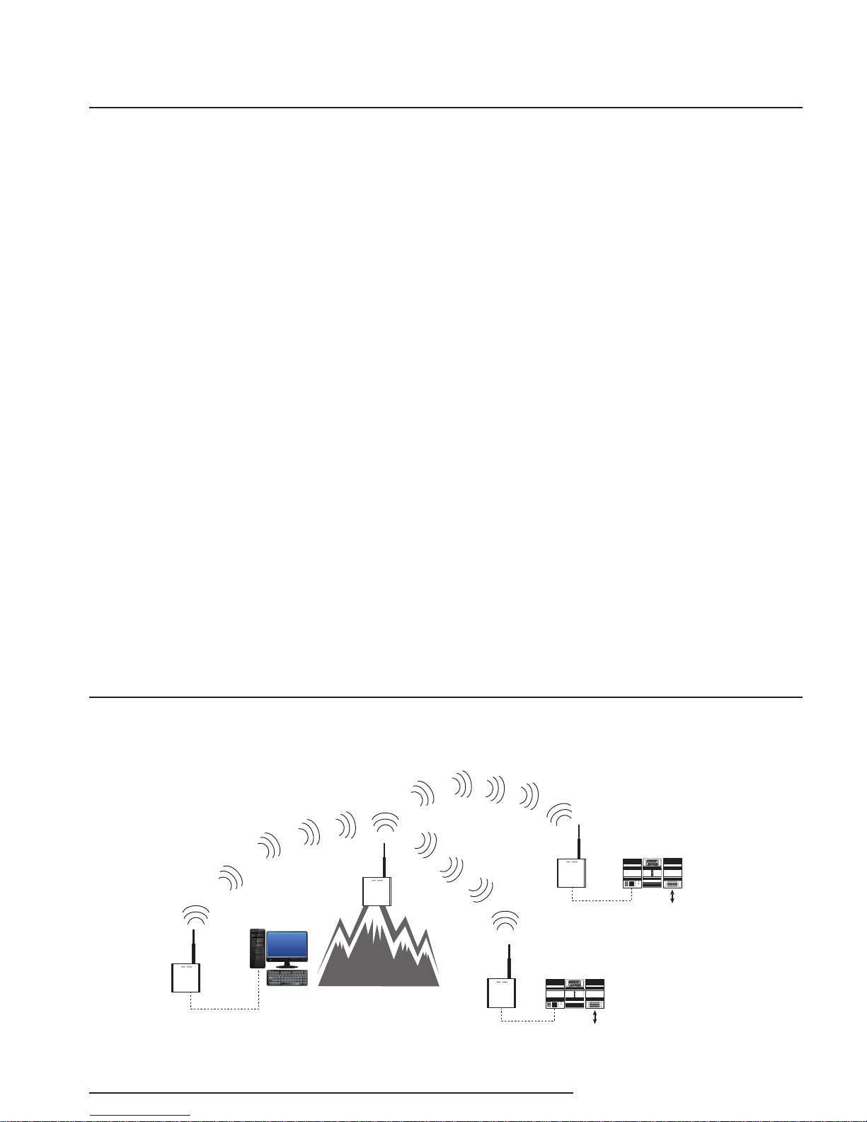
For expanded systems, or applications that may
require communicating beyond hills or longer
distances, the WNM may be congured to include
repeaters with a virtually unlimited number of WNM
transceiver remote sites all communicating back to a
master WNM. Communications may be one-way,
two-way back to the master site, or effectively from
any site-to-any site.
WNM transceivers obtain optimum range by careful
selection of antenna, antenna location, signal gain
parameters, coaxial cable, surge protection, and
conguration of the transceiver setup parameters
to match your particular application. We encourage
you to contact Moore Industries’ support personnel
to set up your WNM transceivers in advance of
purchase. The WNM Conguration Manager software
can also be used to make setup changes to your
wireless system, such as the addition of a new WNM
transceiver site for your applications.
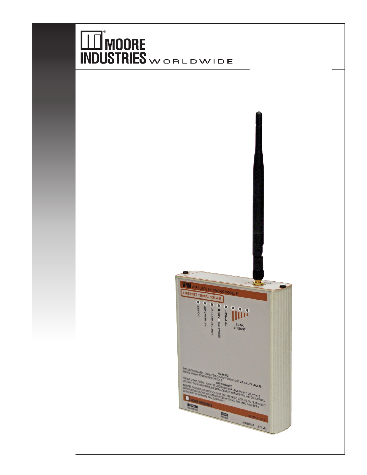
Each WNM radio includes a 2 dBi exible antenna
which mounts directly to the RF connector on the top
of the WNM. This is used for bench testing prior to
system deployment. This antenna is usually replaced
by a coaxial cable and a larger antenna for greater
communications range.
The use of radios may be unfamiliar to some
personnel. Please use this manual as your guide
for your WNM radio familiarization, performance,
installation guidelines, safety considerations, and
diagnosis of operation.
Figure 1. Typical WNM wireless network system using Master, Repeater and Remotes.
The Interface Solution Experts 5

About this Manual
WNM
Wireless
Network Module
Wherever you see a “WARNING”, “Caution” or “Note”
pay particular attention.
WARNING - provides information on steps to take in
avoiding procedures and practices that could pose
safety risks to personnel.
Caution - provides information on steps to take in
avoiding procedures and practices that could risk
damage to the WNM or other equipment.
Note - provides information to help you avoid minor
inconveniences during calibration, installation, or
operation of the WNM.
Specifications
Operating
Frequency
Transmitter
Range
902-928 MHz;
2.4-2.4835 GHz
(Frequency bands may
vary by country)
Range: Up to 30 miles
(48km), line-of-sight using
902-928 units; up to 15
miles (24km) using
2.4-2.4835 units; both sites
using highly-directional
antennas and direct
line-of-sight RF path
Output Power:
10mW to 1W; 10-30dbm
(programmable levels)
Modulation: Spread
spectrum, frequency
hopping (programmable)
NOTE: Transmitter power
may vary by country.
Communications range is
affected by antenna types
and installation heights,
coax length, RF power,
pathway attenuation due
to weather, propagation,
foliage and terrain;
electrical/RF interference
and data rates.
Receiver
Sensitivity
Channel
Data Rates
RF Data
Transfer
Protocols
Operating
Modes
Connectors
1.1Mbps:-97dBm;
345kbps:-104dBm;
both at 10-6 BER
1.1Mbps or 345kbps
Error Detection: 32 bit CRC;
ARQ (Auto Resend Query)
Security: 128 bit AES
encryption
Ethernet
RJ45 Port: All standard IEEE
Ethernet 802.3 protocols
Serial Data Ports: Data sent
within TCP packets;
MODBUS RTU, DF1, ASCII and
DNP3
Point-to-point; Smart Switched
Ethernet; and Store and
Forward Repeater
(programmable)
RF: SMA-RP
Serial Data Ports: DB9F (RS-
232) and 5 pin with mate
(RS-485/422) with RS-485
terminator switches;
Ethernet: RJ45 for data and
configuration
Antenna
Indicators
External
Power
Enclosure
Ambient
Conditions
Weight
Flexible SMA-RP-male
with flex base (optional
external antennas)
LEDs for: Power, RF
Transmit, Link/RF
Receive, RS-485/232,
Signal strength; Ethernet
Voltage: 10-24Vdc
Power: 12 Watts peak,
5 Watts receive
Extruded aluminum
with 35mm DIN top
hat mount
Operating and Storage
Range: -40°C to +75°C
(-40°F to +167°F)
Relative Humidity:
5 to 95%, noncondensing
Shock: IEC 60068-2-6
(20G, 3 axis)
Vibration:
IEC 60068-2-27
(5g, 10-150 Hz)
454g (1 lb.)
6 The Interface Solution Experts
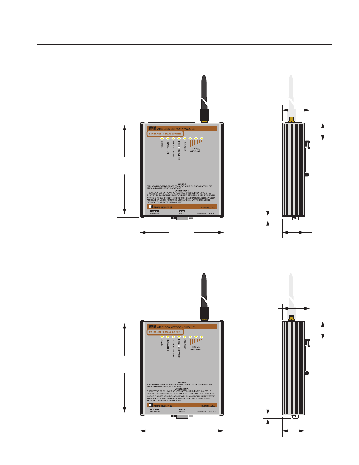
Figure 2. WNM Current Installation Dimensions.
WNM
Wireless
Network Module
900 MHZ
135mm
(5.3 in)
118mm
(4.64 in)
36mm
(1.52 in)
4.8mm
(.19 in)
25mm
(.98 in)
REF
31mm
(1.23 in)
2.4 GHZ
135mm
(5.3 in)
36mm
(1.52 in)
4.8mm
(.19 in)
118mm
(4.64 in)
The Interface Solution Experts 7
25mm
(.98 in)
REF
31mm
(1.23 in)

Figure 3. WNM Legacy Installation Dimensions.
WNM
Wireless
Network Module
Ethernet Radio
117mm
(4.6 in)
53mm
(2.1 in)
31mm
(1.25 in)
REF
Serial Radio
94mm
(3.7 in)
114mm
(4.5 in)
104mm
(4.1 in)
41mm
(1.6 in)
52mm
(2.05 in)
23mm
(.93 in)
REF
44mm
(1.74 in)
8 The Interface Solution Experts
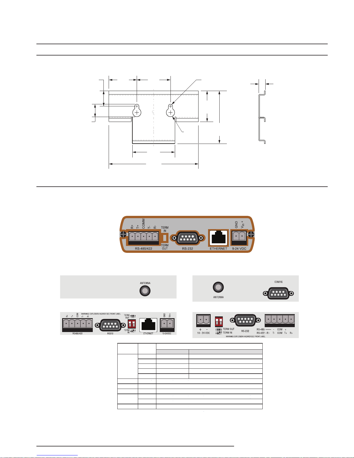
Figure 3. WNM Optional Mounting Bracket P/N 207-256-07
WNM
Wireless
Network Module
14mm
(.56 in)
17mm
(.69 in)
31mm
(1.25 in)
38mm
(1.5 in)
48mm
(1.9 in)
101mm
(4.0 in)
Figure 4. WNM Terminal Designations For Ethernet and Serial Models
Current Ethernet 900MHz & 2.4GHz
Ø9.5mm
(Ø.375 in)
Ø4.7mm
(Ø.187 in)
34mm
(1.37 in)
REF
59mm
(2.35 in)
7mm
(.29 in)
Legacy Ethernet 900MHz & 2.4GHz
RS485/422
RS232 N/A wired as DCE; same serial data content as RS485/422 and as Ethernet
Term In/Out N/A
Ethernet N/A Use straight Ethernet cable to LAN switch or crossover cable to NCS.
Power
Config N/A wired as DCE; no data; use for WNM Legacy Serial only configuration only
* Use care when grounding WNM to prevent ground loops. Power supply GND is internally connected
also to WNM metal case, RF connector, DB9 connectors, signal GND within DB9, and COM. Ground
cables properly. Do not use WNM as a grounding junction block. Avoid ground loops by
following proper shield grounding practices.
Legacy Serial 900MHz & 2.4GHz
Top
Bottom
TerminalInput Type
R +
T +
COM
T -
R -
GND Power Supply return (-), connects to WNM case/ground *
Vin + Power Supply (+), 10 to 24 Vdc regulated
Description
2-Wire RS485 4-Wire RS485 and 4 wire RS422
Jumper to “T+”
to other device '+'
shield, if used *
to other device '-'
Jumper to “T-”
RS485 only if required. Insert termination resistors to minimize noise.
to other device 'T+'
to other device 'R+'
shield, if used *
to other device 'R-'
to other device 'T-'
The Interface Solution Experts 9
Top
Bottom

Quick Setup Guide
WNM
Wireless
Network Module
WARNING
Please review the Important Safety
Information in the Installation section of this
manual before proceeding.
The following guide provides an outline of the steps
to planning, configuring and installing your WNM
network. For more detailed information please refer to
the relevant topics in this manual.
Network Architecture
1. Hand sketch your system on paper as to
physical layout (map). This includes the host
site plus all remote sites. It includes antenna
positions, distances, hills, and intervening
buildings/obstructions in the radio signal
pathway.
2. Determine where the ‘Master radio’ is to be
located (usually adjacent to the host NCS/
PLC/DCS).
3. Determine the need to provide a radio
repeater site for ‘far distant’ sites that cannot
‘see’ the ‘Master radio’. More than one
repeater may be required.
4. Determine if communications are to be
Ethernet, Serial, or both.
5. For long distance radio paths, or radio paths
that intersect other radio systems, perform
a radio ‘site survey’ using actual radios to
confirm that radio communications paths are
reliable for the various sites.
6. Determine your network architecture (one
site to one other site, or more than two sites)
Installation Planning
1. Select best locations for the WNM(s).
Generally these would be located closest
to their antenna, not their process
control equipment, to achieve the best
communication range. The WNM is usually
installed at the entrance of a building in a
weather resistant housing. Also included is
any RF (lighting) coax cable surge protection
plus a lighting earth rod at ground level.
Preferred is a short coax cable length from
the rooftop/tower to the WNM.
2. Select the optimum locations for your
antennas. Ideally these will be the physically
highest points such as atop a mast/pole
at the top of a building or tower with a
straight line of site from the antenna to
distant antenna(s) at other locations. The
higher the location of the antenna, the fewer
opportunities for the RF signal to reflect from
nearby surfaces to degrade the overall RF
signal strength.
3. Select suitable antenna types. An
omnidirectional antenna is well suited
for master control points with remote
sites in different directions. A directional
(Yagi) antenna is best suited for point-topoint applications. Other antenna types
are available that are better suited for
applications where it is desirable to ‘hide’
the presence of the antennas. These may
include spike or flat panel antennas. Consult
Moore Industries for selection of these
antennas.
4. Select antenna gains. An antenna with
increased gain is generally recommended
to offset the losses of RF coaxial cable and
to increase effective radiated power for
improved communications range.
10 The Interface Solution Experts
Warning:
Local and National Government guidelines
limit the effective radiated RF energy. Moore
Industries will assist in calculating the correct
radio power, antenna gains and RF cable
losses for your particular installation.

Configuration
WNM
Wireless
Network Module
Your WNM radios are pre-configured at Moore
Industries and are ready to use out of the box. If your
radios are purchased as part of a Moore Industries’
system, the radios have already been tested with
your particular system. The WNMs are also tagged to
identify their relative installation location.
The WNM Configuration program can be used to
modify and save the WNM setup and also to monitor
WNM radio performance. Please see the Configuration
section for more information.
Bench Setup
It is recommended to test your system setup in a lab
environment before installing in the field (if this is
practical).
1. Before connecting your WNM radios, hook
up your system with cables (Ethernet/
serial) and verify your system is successfully
communicating.
2. Replace the cables with the pre-configured
WNMs (using the tags to identify their
network location). For this test, the flexible
antenna already installed on the WNM can
be used.
3. Power up the system and simulate a signal
at one site. Monitor its appearance on
the other site. Check led activity on each
WNM communications port (see Figure 7
in Operation & Diagnostics section for LED
information).
Field Installation
1. Move the WNMs into their final (permanent)
enclosures.
2. Replace the short flexible antennas on
the WNMs with their coaxial cables, surge
suppressors and antennas. The short
antennas should be stored safely (for future
maintenance purposes, as desired).
3. Verify the correct WNM radios (refer to
factory tags regarding Master and various
Remote) are installed at their correct sites.
4. Repeat your communications test.
5. If there are problems, note all LED status
indicators and contact Moore Industries
technical support.
Caution:
The optimum and safe use of WNM radios,
coaxial cable, surge protection devices,
and antennas requires an added RF (radio
frequency) knowledge that may not already
be in the experience set for some designers,
installers and maintenance personnel. Please
review all topics of this manual for more
detailed information and review and comply
with any local building codes.
4. Simulate data signals between all sites and
verify that they are communicating.
The Interface Solution Experts 11

Network Architecture
WNM
Wireless
Network Module
Prior to configuring your WNMs, you must first design
your network to determine the location, number and
types of WNMs required. Please review the sections
below for more information on radio and network types
to help in your network design.
1. Hand sketch your system on paper as to
physical layout (map). This includes the host
site plus all remote sites. It includes antenna
positions, distances, hills, and intervening
buildings/obstructions in the radio signal
pathway.
2. Determine where the ‘Master radio’ is to be
located (usually adjacent to the host NCS/
PLC/ DCS). All radio communications will be
routed through the Master radio regardless of
data origin and data destination.
3. Determine the need to provide a radio
repeater site for ‘far distant’ sites that cannot
‘see’ the ‘Master radio’.
4. Determine if communications are to be
Ethernet, serial, or both.
5. Perform a radio ‘site survey’ using actual
radios to confirm that radio communication
paths are reliable for the various sites. This is
particularly important for long distance radio
paths plus radio paths that intersect other
radio systems.
6. Contact Moore Industries-International
technical support staff for any questions and
assistance.
Radio Type
Each network consists of a one Master radio plus one
or more Remote radios. If a radio (Master or Remote)
pathway is obstructed or too distant to another radio,
then a Repeater radio must be added to the link.
Master Radio
All WNM communication network types must have a
Master radio. There is always only one Master radio
per WNM communications network. The Master radio
is physically identical to any other radio. It is given its
Master assignment and its own address at the time of
network configuration. In most WNM communications
networks, the Master radio is used to direct radio
traffic to/from each of the other radios. Thus, in most
networks, radio traffic to/from all of the other radios
is routed through the Master radio. The Master radio
is usually located at the site that has the most data
transfer. An example would be the host computer
site of a large facility that communicates with multiple
remote locations. By locating the Master radio at
this busy site, the minimum number of radio pathway
transactions is required for network communications.
Remote Radio
All network types have one or more Remote radios.
The Remote radio is physically identical to any other
radio. It receives its Remote assignment at the time
of network configuration. In most WNM network
types, the Remote radio communicates via a radio
addressing pathway through the Master radio. This
includes communications from one Remote site to
another Remote site, in most networks. The Remote
radios are usually located at the remote sites. Remote
radio sites may be added at any time to the network
by configuring the remote to communicate with a
particular other radio address, usually the Master or a
Repeater.
12 The Interface Solution Experts
 Loading...