

Moore Inductries IPH2, IPX2 User Manual
2
2
December 2016
170-775-00G
IPH
& IPX
Current-to-Pressure
(I/P) Transmitters
Transmitters
Current-to-Pressure
(I/P)
2
& IPX
2
IPH

2
IPH
Current-to-Pressure
(I/P) Transmitters
&
2
IPX
Table of Contents
Introduction .........................................................................................................3
The IPH2 & IPX2 ..................................................................................................3
Specications .....................................................................................................4
IPX2 Dimensional Diagram .................................................................................5
IPH2 Dimensional Diagram ................................................................................6
Calibration ...........................................................................................................7
Necessary Equipment and Calibration Preparation .............................................................7
Calibration Process .......................................................................................................... 7-9
Installation .........................................................................................................10
Phase One: Mounting ........................................................................................................10
Phase Two: Electrical Connections ....................................................................................10
Phase Three: Pneumatic Connections ...............................................................................11
Hazardous Location Applications ................................................................... 12
Operation ...........................................................................................................13
Maintenance ...................................................................................................... 13
Troubleshooting the IPH2 & IPX2 .....................................................................14
2
IPX
Customer Service ............................................................................................. 15
Intrinsically Safe Diagram................................................................................16
Return Procedures .......................................................................................... 19
Replacement Modules .............................................................................14
2 Demand Moore Reliability

IPH
2
&
IPX
2
Current-to-Pressure
(I/P) Transmitters
Introduction
This users’ manual for Moore Industries’ IPH2 and
IPX2 Current-to-Pressure Transmitters contains all
of the information that is needed to calibrate, install,
operate, maintain, and troubleshoot this family of
transmitters.
The following guidelines are used in this manual:
WARNING - Hazardous procedure or condition that
could injure the operator.
Caution - Hazardous procedure or condition that could
damage or destroy the unit.
Note - Information that is helpful for a procedure,
condition, or operation of the unit.
About this Manual
Wherever you see a “WARNING”, “Caution”
or “Note” pay particular attention.
WARNING - Hazardous procedure or condition that
could injure the operator.
Caution - Hazardous procedure or condition that could
damage or destroy the unit.
Note - Information that is helpful for a procedure,
condition, or operation of the unit.
IPH2 & IPX
The rugged IPH2 and IPX2 Current-to-Pressure (I/P)
Transmitters are designed specically for extended
duty in harsh eld environments. Being Type
3X/4X- and IP56/IP66-rated, the extruded aluminum
housings, for both the IPH2 and IPX2, oer water
and dust protection and are also highly resistant to
corrosion and chemicals. In addition, while the air and
natural gas versions of the IPX2 are explosion-proof,
the later oers an increased ingress protection of IP66.
These 2-wire (loop-powered) transmitters convert
a current signal to a pneumatic signal so that an
electronic-based system such as a DCS, PLC, or PC
can control a pneumatic actuator, valve, or damper
drive. Available models accept a wide range of current
inputs (4-20mA, 4-12mA, and 12-20mA) and provide a
proportional pneumatic signal (3-15psig, 0.2-1Bar,
20-100kPA, etc.). A reverse pneumatic output option
is available for the IPH2. Reverse output is switch
selectable on new versions of the IPX2 (introduced in
2013).
The high-performance line of I/P transmitters
utilizes an internal feedback loop to ensure accurate
operation. The feedback loop consists of an internal
pressure transducer that samples the unit’s output
pressure and compares it to the input signal. This
allows the unit’s output to track the input signal. Other
I/P transmitters, such as our original IPT, IPH and IPX
models, rely solely on mechanical positioning.
Since the feedback loop requires power to operate,
when there is no input power to the unit, the pneumatic
output will be shut o. Units that use mechanical
positioning only, will typically still have a pneumatic
output when power is removed. By example, a unit
(IPT, IPH and IPX) with an output range of 15 - 3PSIG
will output approximately 18PSIG when the input
signal is removed. This is not an issue except for
those users that rely on this elevated output (18PSIG)
to maintain a valve’s position upon the unexpected
loss of input signal (4-20mA). In such cases, the IPT2,
IPH2 and IPX2 units react dierently by shutting o the
pneumatic output.
Both units are available with an optional coalescing
lter/regulator that combines an air lter and miniature
supply line regulator with a pressure gauge that reads
in both psi and Bars.
2
Demand Moore Reliability 3

2
IPH
&
IPX
Current-to-Pressure
(I/P) Transmitters
Specifications
2
Performance
Accuracy: <±0.25% of span
including the combined eect
of linearity, hysteresis and
repeatability (between
0 and 3psig output, error will
not exceed ±1.0% of span)
Stability: Not to degrade
from stated accuracy for six
months
Step Response: <0.2
seconds into 100ml load
3
(6 in
) from 10% to 90% of
span; Not guaranteed below
3psig output
Supply Pressure Eect:
Negligible from 20-40psig,
steady pressure
Air Capacity:
5.0SCFM minimum (20psig
supply, 0psig output)
Relief Capacity: 2.5SCFM
minimum (15psig output)
Air Supply: Instrument air
only, 20-40psig.
Gas Supply with -NG1 or
-NG2 Option: 17-40psig.
Same cleanliness as
instrument air. H
exceed 20ppm
Maximum Input: 80psig
without damage for units with
output pressure rating of
>15psig; 45psig without
damage for units with output
pressure rating of ≤ 15psig
S not to
2
Performance
(Continued)
Voltage Drop:
5V, maximum
Air Consumption
(Dead-ended):
At 3-15psig output 20psig
supply, average steady state
consumption* of 4.7SCFH
(min 4.2SCFH@ 3psig, max
5.2SCFH@15psig);
40psig supply, max 9SCFH
@15psig output;
40psig supply, max 10SCFH
@30psig output
Natural Gas Consumption
(Dead-ended):
At 3-15psig output 20psig
supply, average steady state
consumption* of 5.7SCFH,
(min 5.1SCFH@ 3psig, max
6.2SCFH@15psig);
17psig supply, max 5.9SCFH
@15psig output;
40psig supply, max 12SCFH
@30psig output;
Mounting Position Eect:
Negligible, unit can be
mounted in any position;
refer to user manual for
special conditions of use with
natural gas supply or outdoor
environments.
Ambient
Conditions
Adjustment
Weight
*Average ow rate determined at 9 psig output
Operating & Storage
Range:
-40°C to +85°C
(-40°F to +185°F)
Ambient Temperature
Eect: <±0.025% of
span/°C, maximum from
-20°C to 80°C;
<±0.1% of span/°C,
maximum
RFI/EMI Eect:
<±0.25% of span change
at in eld strengths of
10V/m@ frequencies of
20-1000MHz
Vibration Eect: Meets
ANSI/ISA-75 13.01-1996
(R2007) 5.3.5 as follows:
5-15Hz, 2mm peak-topeak; 15-150Hz, 1g;
150-2000Hz, 0.5g
Relative Humidity:
0-100%, non-condensing
Zero & Span: Screw
adjusts zero or span by
±10% minimum, noninteractive
2
IPH
: 1.14kg (2.5 lbs)
IPX2: 2.4kg (5.3 lbs)
Specifications and information subject to change without notice.
4 Demand Moore Reliability
IPH
2
&
IPX
2
Current-to-Pressure
(I/P) Transmitters
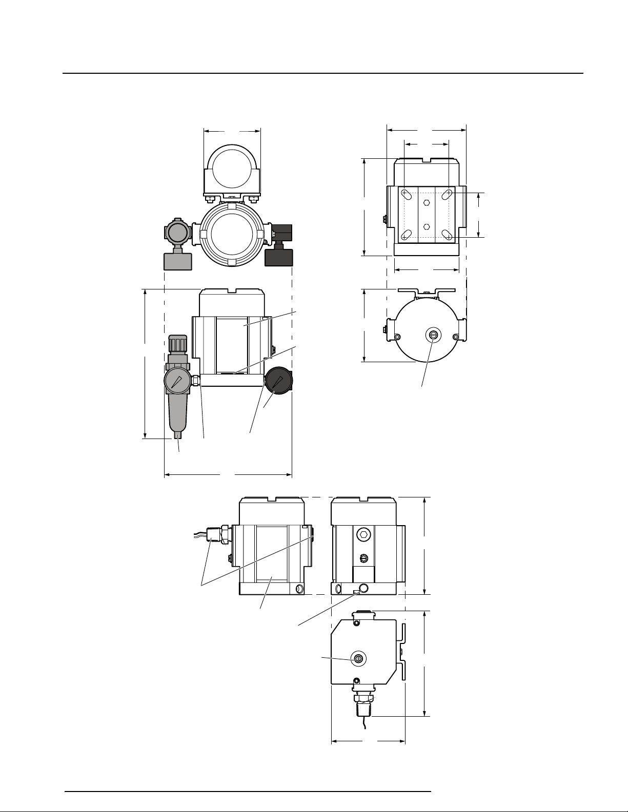
Figure 1. IPX 2 Current-to-Pressure Transmitter Housing Dimensions
VENT
OUT
OUT
Instrument Tag
Manual override &
filter holder
Both side fittings are
permanently attached.
Do not attempt to remove.
(They may be installed on
either side of the unit by
the factory)
Natural gas vent (-NG option)
See Pneumatic Connections section
166
(6.5)
117
(4.6)
154
(6.1)
Manual override &
filter holder
125
(4.9)
70
(2.8)
70
(2.8)
154
(6.1)
102
(4.0)
117
(4.6)
-FR1 Option
-GA Option
Instrument
Tag
Pneumatic
input port
1/4 NPT
female
Pneumatic
output port
1/4 NPT
female
Open vent
(air model only)
200
(7.9)
239
(9.4)
89
(3.5)
NG
Option
Demand Moore Reliability 5
2
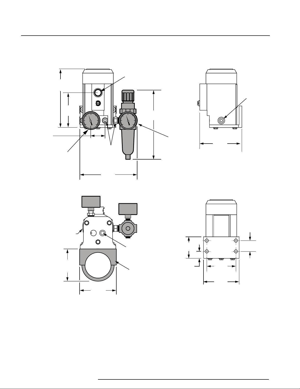
33mm
(1.3 in)
1/4 NPT FEMALE
PNEUMATIC OUTPUT
PORT (COVERED BY
OPTIONAL –GA
OUTPUT GAUGE)
137mm
(5.4 in)
86mm
(3.4 in)
MANUAL OVERRIDE
& FILTER HOLDER
72mm
(2.9 in DIA.)
76mm
(3.0 in)
REF.
69mm
(2.7 in)
16mm
(0.65 in)
51mm
(2.0 in)
83mm
(3.3 in)
1/4 NPT
FEMALE
PNEUMATIC
INPUT
PORT
163mm
(6.4 in)
135mm
(5.3 in)
WITH –FR1 OPTION
1/4 NPT FEMALE
PNEUMATIC INPUT
PORT (UNUSED PORT
IS PLUGGED)
CONDUIT WIRE ENTRY
METRIC (M20 x 1.5)
OR NPT (1/2-14)
THREADS
99mm
(3.9 in)
-P OPTION
2 INCH PIPE
MOUNTING
BRACKET
1/4 NPT
PNEUMATIC
INPUT PORT
FOR OPTIONAL
–FR1 FILTER/
REGULATOR/
GAUGE
76mm
(3.0 in)
25mm
(1.0 in)
IPH
&
2
IPX
Current-to-Pressure
(I/P) Transmitters
Figure 2. IPH 2 Current-to-Pressure Transmitter Housing Dimensions
6 Demand Moore Reliability
 Loading...