

2
2
December 2016
170-775-00G
IPH
& IPX
Current-to-Pressure
(I/P) Transmitters
Transmitters
Current-to-Pressure
(I/P)
2
& IPX
2
IPH

2
IPH
Current-to-Pressure
(I/P) Transmitters
&
2
IPX
Table of Contents
Introduction .........................................................................................................3
The IPH2 & IPX2 ..................................................................................................3
Specications .....................................................................................................4
IPX2 Dimensional Diagram .................................................................................5
IPH2 Dimensional Diagram ................................................................................6
Calibration ...........................................................................................................7
Necessary Equipment and Calibration Preparation .............................................................7
Calibration Process .......................................................................................................... 7-9
Installation .........................................................................................................10
Phase One: Mounting ........................................................................................................10
Phase Two: Electrical Connections ....................................................................................10
Phase Three: Pneumatic Connections ...............................................................................11
Hazardous Location Applications ................................................................... 12
Operation ...........................................................................................................13
Maintenance ...................................................................................................... 13
Troubleshooting the IPH2 & IPX2 .....................................................................14
2
IPX
Customer Service ............................................................................................. 15
Intrinsically Safe Diagram................................................................................16
Return Procedures .......................................................................................... 19
Replacement Modules .............................................................................14
2 Demand Moore Reliability

IPH
2
&
IPX
2
Current-to-Pressure
(I/P) Transmitters
Introduction
This users’ manual for Moore Industries’ IPH2 and
IPX2 Current-to-Pressure Transmitters contains all
of the information that is needed to calibrate, install,
operate, maintain, and troubleshoot this family of
transmitters.
The following guidelines are used in this manual:
WARNING - Hazardous procedure or condition that
could injure the operator.
Caution - Hazardous procedure or condition that could
damage or destroy the unit.
Note - Information that is helpful for a procedure,
condition, or operation of the unit.
About this Manual
Wherever you see a “WARNING”, “Caution”
or “Note” pay particular attention.
WARNING - Hazardous procedure or condition that
could injure the operator.
Caution - Hazardous procedure or condition that could
damage or destroy the unit.
Note - Information that is helpful for a procedure,
condition, or operation of the unit.
IPH2 & IPX
The rugged IPH2 and IPX2 Current-to-Pressure (I/P)
Transmitters are designed specically for extended
duty in harsh eld environments. Being Type
3X/4X- and IP56/IP66-rated, the extruded aluminum
housings, for both the IPH2 and IPX2, oer water
and dust protection and are also highly resistant to
corrosion and chemicals. In addition, while the air and
natural gas versions of the IPX2 are explosion-proof,
the later oers an increased ingress protection of IP66.
These 2-wire (loop-powered) transmitters convert
a current signal to a pneumatic signal so that an
electronic-based system such as a DCS, PLC, or PC
can control a pneumatic actuator, valve, or damper
drive. Available models accept a wide range of current
inputs (4-20mA, 4-12mA, and 12-20mA) and provide a
proportional pneumatic signal (3-15psig, 0.2-1Bar,
20-100kPA, etc.). A reverse pneumatic output option
is available for the IPH2. Reverse output is switch
selectable on new versions of the IPX2 (introduced in
2013).
The high-performance line of I/P transmitters
utilizes an internal feedback loop to ensure accurate
operation. The feedback loop consists of an internal
pressure transducer that samples the unit’s output
pressure and compares it to the input signal. This
allows the unit’s output to track the input signal. Other
I/P transmitters, such as our original IPT, IPH and IPX
models, rely solely on mechanical positioning.
Since the feedback loop requires power to operate,
when there is no input power to the unit, the pneumatic
output will be shut o. Units that use mechanical
positioning only, will typically still have a pneumatic
output when power is removed. By example, a unit
(IPT, IPH and IPX) with an output range of 15 - 3PSIG
will output approximately 18PSIG when the input
signal is removed. This is not an issue except for
those users that rely on this elevated output (18PSIG)
to maintain a valve’s position upon the unexpected
loss of input signal (4-20mA). In such cases, the IPT2,
IPH2 and IPX2 units react dierently by shutting o the
pneumatic output.
Both units are available with an optional coalescing
lter/regulator that combines an air lter and miniature
supply line regulator with a pressure gauge that reads
in both psi and Bars.
2
Demand Moore Reliability 3

2
IPH
&
IPX
Current-to-Pressure
(I/P) Transmitters
Specifications
2
Performance
Accuracy: <±0.25% of span
including the combined eect
of linearity, hysteresis and
repeatability (between
0 and 3psig output, error will
not exceed ±1.0% of span)
Stability: Not to degrade
from stated accuracy for six
months
Step Response: <0.2
seconds into 100ml load
3
(6 in
) from 10% to 90% of
span; Not guaranteed below
3psig output
Supply Pressure Eect:
Negligible from 20-40psig,
steady pressure
Air Capacity:
5.0SCFM minimum (20psig
supply, 0psig output)
Relief Capacity: 2.5SCFM
minimum (15psig output)
Air Supply: Instrument air
only, 20-40psig.
Gas Supply with -NG1 or
-NG2 Option: 17-40psig.
Same cleanliness as
instrument air. H
exceed 20ppm
Maximum Input: 80psig
without damage for units with
output pressure rating of
>15psig; 45psig without
damage for units with output
pressure rating of ≤ 15psig
S not to
2
Performance
(Continued)
Voltage Drop:
5V, maximum
Air Consumption
(Dead-ended):
At 3-15psig output 20psig
supply, average steady state
consumption* of 4.7SCFH
(min 4.2SCFH@ 3psig, max
5.2SCFH@15psig);
40psig supply, max 9SCFH
@15psig output;
40psig supply, max 10SCFH
@30psig output
Natural Gas Consumption
(Dead-ended):
At 3-15psig output 20psig
supply, average steady state
consumption* of 5.7SCFH,
(min 5.1SCFH@ 3psig, max
6.2SCFH@15psig);
17psig supply, max 5.9SCFH
@15psig output;
40psig supply, max 12SCFH
@30psig output;
Mounting Position Eect:
Negligible, unit can be
mounted in any position;
refer to user manual for
special conditions of use with
natural gas supply or outdoor
environments.
Ambient
Conditions
Adjustment
Weight
*Average ow rate determined at 9 psig output
Operating & Storage
Range:
-40°C to +85°C
(-40°F to +185°F)
Ambient Temperature
Eect: <±0.025% of
span/°C, maximum from
-20°C to 80°C;
<±0.1% of span/°C,
maximum
RFI/EMI Eect:
<±0.25% of span change
at in eld strengths of
10V/m@ frequencies of
20-1000MHz
Vibration Eect: Meets
ANSI/ISA-75 13.01-1996
(R2007) 5.3.5 as follows:
5-15Hz, 2mm peak-topeak; 15-150Hz, 1g;
150-2000Hz, 0.5g
Relative Humidity:
0-100%, non-condensing
Zero & Span: Screw
adjusts zero or span by
±10% minimum, noninteractive
2
IPH
: 1.14kg (2.5 lbs)
IPX2: 2.4kg (5.3 lbs)
Specifications and information subject to change without notice.
4 Demand Moore Reliability
IPH
2
&
IPX
2
Current-to-Pressure
(I/P) Transmitters
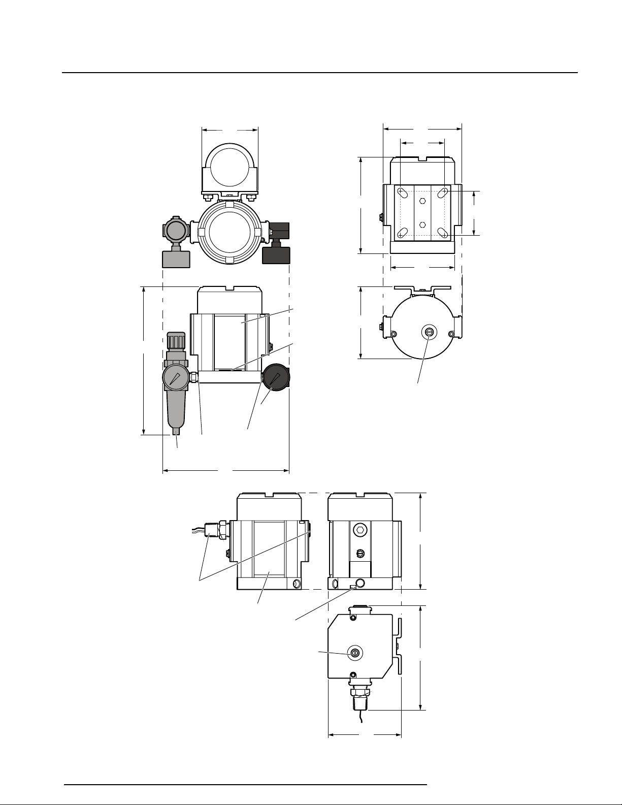
Figure 1. IPX 2 Current-to-Pressure Transmitter Housing Dimensions
VENT
OUT
OUT
Instrument Tag
Manual override &
filter holder
Both side fittings are
permanently attached.
Do not attempt to remove.
(They may be installed on
either side of the unit by
the factory)
Natural gas vent (-NG option)
See Pneumatic Connections section
166
(6.5)
117
(4.6)
154
(6.1)
Manual override &
filter holder
125
(4.9)
70
(2.8)
70
(2.8)
154
(6.1)
102
(4.0)
117
(4.6)
-FR1 Option
-GA Option
Instrument
Tag
Pneumatic
input port
1/4 NPT
female
Pneumatic
output port
1/4 NPT
female
Open vent
(air model only)
200
(7.9)
239
(9.4)
89
(3.5)
NG
Option
Demand Moore Reliability 5
2
33mm
(1.3 in)
1/4 NPT FEMALE
PNEUMATIC OUTPUT
PORT (COVERED BY
OPTIONAL –GA
OUTPUT GAUGE)
137mm
(5.4 in)
86mm
(3.4 in)
MANUAL OVERRIDE
& FILTER HOLDER
72mm
(2.9 in DIA.)
76mm
(3.0 in)
REF.
69mm
(2.7 in)
16mm
(0.65 in)
51mm
(2.0 in)
83mm
(3.3 in)
1/4 NPT
FEMALE
PNEUMATIC
INPUT
PORT
163mm
(6.4 in)
135mm
(5.3 in)
WITH –FR1 OPTION
1/4 NPT FEMALE
PNEUMATIC INPUT
PORT (UNUSED PORT
IS PLUGGED)
CONDUIT WIRE ENTRY
METRIC (M20 x 1.5)
OR NPT (1/2-14)
THREADS
99mm
(3.9 in)
-P OPTION
2 INCH PIPE
MOUNTING
BRACKET
1/4 NPT
PNEUMATIC
INPUT PORT
FOR OPTIONAL
–FR1 FILTER/
REGULATOR/
GAUGE
76mm
(3.0 in)
25mm
(1.0 in)
IPH
&
2
IPX
Current-to-Pressure
(I/P) Transmitters
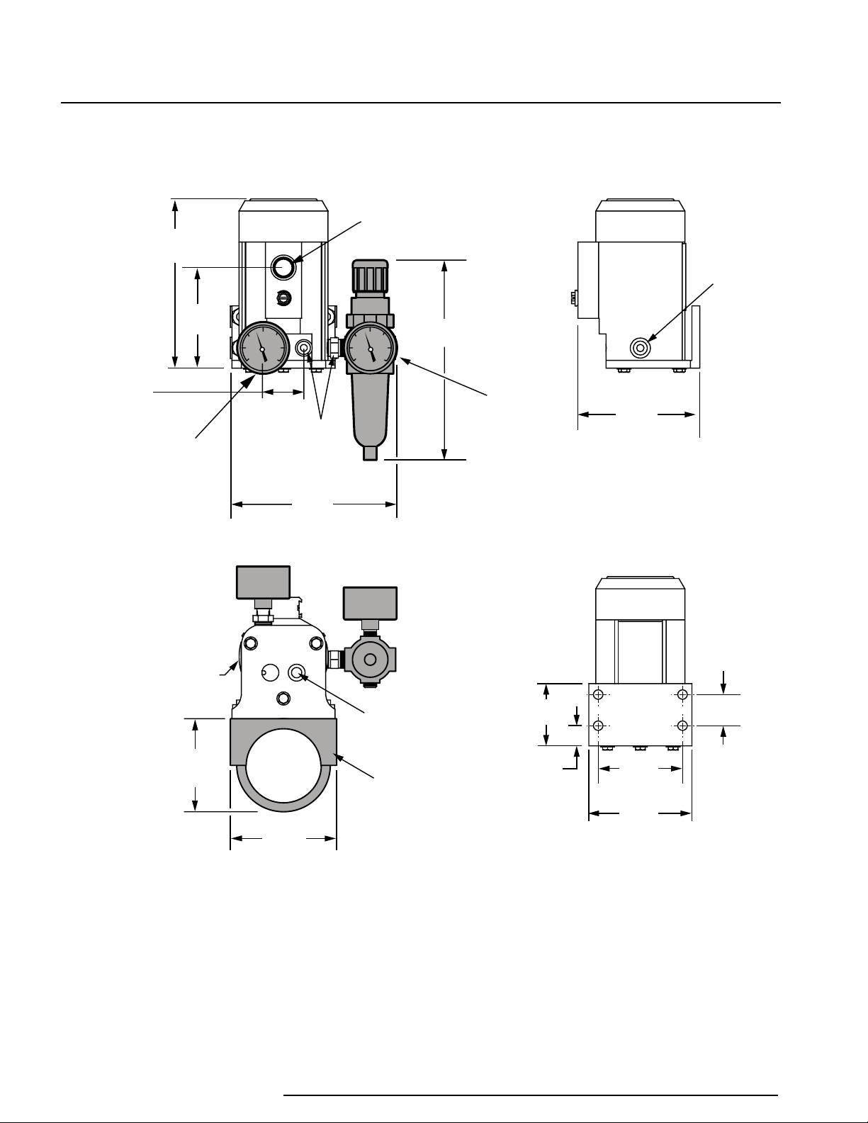
Figure 2. IPH 2 Current-to-Pressure Transmitter Housing Dimensions
6 Demand Moore Reliability

IPH
2
&
IPX
2
Current-to-Pressure
(I/P) Transmitters
Calibration
Every IPH2 and IPX2 is fully tested and calibrated at the
factory prior to shipment. However, before installation,
your IPH2 or IPX2 should be bench-checked to verify
the desired unit zero and unit span. Calibration should
be conducted in an appropriate testing environment.
Necessary Equipment
Table 1 lists the equipment required to calibrate
the unit. This equipment is not supplied by Moore
Industries, but should be available in most labs or
maintenance areas.
Table 1. IPH 2 & IPX 2 Calibration Equipment
Adjustable current source
DC Multimeter
Instrument air supply
Air pressure gauge #1
Air pressure gauge #2
Pneumatic load
Equipment
4-20mA output
Accurate to ±0.05%
Filtered
Accurate to ±2%
Accurate to ±0.1%
Volume of 7.5 cubic inches
(approx. 120 milliliters)
Description
Note:
Always use clean, dry, instrument air when
calibrating or operating the IPH 2 or IPX 2.
All pneumatic lines used in calibration and operation
must be “blown down” (purged) prior to connection to
the unit. Any condensation or oil residue in the lines,
if introduced into the pneumatic chambers of the unit,
may result in poor unit performance.
Calibration Process
To perform the recommended bench-check for the
IPH2 or IPX2, rst perform the setup as described in
the next section. See Figures 3 and 4 for illustrations
of the Calibration Setup, then follow the steps under
Calibration Setup and Calibrating the IPH2 or IPX2.
Calibration Setup
1. Connect 1/4-inch pneumatic tubing between the
appropriate output port of the regulated instrument
air supply and the pressure gauge #1 (accuracy
of ±2% of span). Connect another tube from the
pressure gauge to the port labeled “IN” on IPH2 or
IPX2.
Preparing for Calibration
To prepare the IPH2 or IPX2 for calibration, remove
the screw-on cap and connect the unit to your
conguration equipment as shown in Figures 3 and 4.
Unit Connections and Controls. The IPH2 and IPX2
each have two labeled terminals on their faceplate,
located under the top protective cover of the housing.
The terminal labeled “+PS” is for connection of the
positive current input, and the terminal labeled “–PS”
is for the negative connection.
The two controls are also located inside the unit
housing under the screw-on cap. They consist of
two potentiometers, each accessed through the front
panel. They are labeled “zero” and “span”. The zero
potentiometer provides a control range for osets of
±10% of rated unit span, while the span potentiometer
adjusts unit full-scale output to 100 percent of rated
span.
Each potentiometer requires approximately 20 turns
to move its wiper from one extreme to the other:
clockwise for maximum, or counterclockwise for
minimum values. Each is equipped with a slip clutch
to prevent damage if the adjustment is turned beyond
the wiper stop.
2. Connect 1/4-inch pneumatic tubing between the
port labeled “OUT” and the appropriate port of
pressure gauge #2 (accuracy of ±0.1% of span),
then from gauge #2 to the appropriate pneumatic
load.
3. Run current source wiring through conduit opening
in housing, and to the front panel of the IPH2 or
IPX2. (Not necessary for IPX2 –NG models.)
4. Connect positive lead of adjustable current source
to the +PS terminal of unit. Connect negative
source lead to the –PS terminal. (For IPX2 –NG,
connect the positive lead of the current source
to the red wire, and the negative lead of current
source to the black wire.) A multimeter may also
be connected to verify level of current input.
5. When connections are complete, apply an input
current of 0% of span. (i.e. 4mA for a 4-20mA unit)
6. Apply appropriate ltered, instrument-quality air to
supply line: 20 or 35psi (1.4Bar to 2.4Bar). Verify
appropriate supply pressure by checking Supply
Pressure eld of unit model number.
7. Allow approximately 30 seconds for calibration
setup to stabilize.
Demand Moore Reliability 7

2
ZERO
2
-PS
+PS
SPAN
+
_
PNEUMATIC
TEST LOAD
REGULATED
INSTRUMENT
AIR SUPPLY
PRESSURE GAUGE #1
(ACCURACY ±2%)
PRESSURE GAUGE #2
(ACCURACY ±0.1%)
ADJUSTABLE
CURRENT
SOURCE
DC
MULTIMETER
+
_
OUTPUT
PORT
INPUT
PORT
IPH
&
IPX
Current-to-Pressure
(I/P) Transmitters
Figure 3. IPH 2 Calibration Setup
2
Figure 4. IPX 2 Calibration Setup
PRESSURE GAUGE #1
(ACCURACY ±2%)
REGULATED
INSTRUMENT
AIR SUPPLY
NOTE: This shows the new version
of IPX2 introduced in 2013. Previous
versions of IPX2 do not have a direct/
reverse switch and only have one set of
potentiometers. (similar to IPH2 in
Figure 3)
8 Demand Moore Reliability
INPUT
PORT
PS (+) PS (-)
SPAN
ZERO
SELECTABLE OUTPUT
IPX
2
OUTPUT
PORT
SPAN
ZERO
PRESSURE GAUGE #2
_
+
ADJUSTABLE
CURRENT
SOURCE
(ACCURACY ±0.1%)
PNEUMATIC
TEST LOAD
+
_
DC
MULTIMETER

IPH
2
&
IPX
2
Current-to-Pressure
(I/P) Transmitters
Calibrating the IPH2 or IPX
This calibration procedure consists of a basic check
and adjustment of unit zero and span, based on the
reading of pressure gauge #2. To calibrate a direct
output unit, perform the following:
1. For IPX2 new versions (introduced in 2013) only,
check switch is set to “Direct”- see Figure 5.
2
10. Monitor reading of pressure gauge #2 (output),
and adjust span potentiometer so that reading is
at 0% of span for your unit (i.e. 3 psi for a 3-15 psi
unit).
11. Repeat steps 8 through 10 until the unit outputs
100% of rated pressure range at 0% current input,
and 0% of output pressure range at 100% of span.
2. Check unit zero setting. Monitor reading of
pressure gauge #2 (output), and turn zero
potentiometer counterclockwise to lower output,
clockwise to raise output. Set zero potentiometer
so that pressure output is at 0% of span when a
current input of 0% of span is applied. (i.e. 3psi for
a 3-15psi unit)
3. Check unit span setting. Increase input to 100%
of rated span (i.e. 20mA for a 4-20mA unit).
4. Monitor reading of pressure gauge #2 (output),
and adjust span potentiometer so that reading is at
100% of span for your unit (i.e. 15psi for a 3-15psi
unit).
5. Repeat steps 1 through 4 until the unit outputs 0%
of rated pressure range at 0% current input, and
100% of output pressure range at 100% of span.
6. Verify the accuracy of your adjustments by
inputting 0%, 25%, 50%, and 75% of span inputs,
and monitoring the output.
To calibrate a reverse output unit, perform the
following:
12. Verify the accuracy of your adjustments by
inputting 0%, 25%, 50%, and 75% of span inputs,
and monitoring the output.
Note:
New versions of the IPX2 (introduced in 2013) have
a selectable output switch. Be sure to set this switch
to the required output mode, direct or reverse, and
use the corresponding set of pots accordingly.
See Figure 5.
Figure 5. IPX 2 Output Switch
Adjustable Direct
Potentiometers
PS (+) PS (-)
SPAN
ZERO
SELECTABLE OUTPUT
SPAN
2
IPX
ZERO
Selectable Output
Switch
Adjustable Reverse
Potentiometers
2
7. For IPX
check switch is set to “Reverse” - see Figure 5.
8. Check unit zero setting. Monitor reading of
pressure gauge #2 (output), and turn zero
potentiometer counterclockwise to lower output,
clockwise to raise output. Set zero potentiometer
so that pressure output is at 100% of span when a
current input of 0% of span is applied. (i.e. 15 psi
for a 3-15 psi unit).
9. Check unit span setting. Increase input to 100%
of rated span (i.e. 20mA for a 4-20mA unit).
new versions (introduced in 2013) only,
Demand Moore Reliability 9

2
IPH
Current-to-Pressure
(I/P) Transmitters
&
2
IPX
Installation
The installation of the IPH2 or IPX2 is carried out in
three phases: the physical mounting of the unit, the
electrical connections phase, and the pneumatic
connections phase. It is strongly suggested that each
unit be calibrated according to the instructions in this
manual before being placed into service.
Installation in hazardous ‘Classied’ locations and
potentially explosive atmospheres must adhere to the
instructions in the Hazardous Location Applications
section which can be found at the end of this
Installation section.
Phase One: Mounting
Figures 1 and 2 give the dimensions of the IPX2 and
IPH2, respectively. The illustrations also give the
dimensions of the available option hardware, which is
recommended for most installations. After placing the
unit in the desired location and orientation, secure the
housing with the optional pipe mounting hardware or
other appropriate fasteners.
The IPH2 or IPX2 will operate when installed at any
angle–either surface-mounted or attached to pipe or
round conduit. However, there are other considerations
in selecting the ideal mounting position. If the IPH2 is
in an area which may be exposed to rain or water, it
should be mounted within 45° of vertical. In natural
gas applications, where liquid remnants are possible
in the supply, the vent port of the IPX2 needs to be
in a position that would allow for sucient draining.
Please also consider the requirements in Pneumatics
Connections on the next page before determining the
ideal mounting conguration.
Phase Two: Electrical Connections
To complete the electrical connections, route the wiring
through the conduit port to the terminal block, then
use a screwdriver to loosen the terminal screws. (Not
necessary for IPX2 –NG1 or –NG2 installation.)
For all units except the IPX2 –NG1 or –NG2, connect
positive lead (+) to the +PS terminal, and negative
lead (–) to the –PS terminal. Tighten the terminal
screws until snug.
Caution:
When connecting the IPX 2 Natural Gas (–NG1 or
–NG2) model, use an appropriately certied conduit
box and wire connectors. Do not attempt to remove
the seal tting, as it is necessary for natural gas
certication. Connect the positive lead (+) to the red
wire from the seal tting, and the negative lead (–) to
the black wire from the seal tting.
Use shielded, twisted-pair wiring for low-level input.
Ground the shielding wire as close as possible to the
installed unit.
Recommended Ground Wiring
Practices
Moore Industries recommends the following ground
wiring practices:
• Any Moore Industries product in a metal case
or housing should be grounded.
• The protective earth conductor must be
connected to a system safety earth ground
before making other connections.
• All input signals to, and output signals
from, Moore Industries’ products should be
wired using a shielded, twisted pair wiring
technique. Shields should be connected to an
earth or safety ground.
• For the best shielding, the shield should be
run all the way from the signal source to the
receiving device. (see Note below)
• The maximum length of unshielded input and
output signal wiring should be 2 inches.
Note:
Some of Moore Industries’ instruments can be
classied as receivers (IPT2, IPX2, etc.) and some
can be classied as transmitters (TRX, TRY, etc.)
while some are both a receiver and a transmitter
(SPA2, HIM, etc). Hence, your shield ground
connections should be appropriate for the type
of signal line being shielded. The shield should
be grounded at the receiver and not at the signal
source.
CE Conformity
Installation of any Moore Industries’ products that carry
the CE marking must adhere to the guidelines in the
Recommended Ground Wiring Practices section in
order to meet the EN 61326 requirements set forth in
the applicable EMC directive.
10 Demand Moore Reliability

IPH
2
&
IPX
2
Current-to-Pressure
(I/P) Transmitters
Phase Three: Pneumatic Connections
To complete the nal phase of installation, connect the
supply line to the ¼-inch NPT female port labeled “IN”.
Connect the output line to the ¼-inch NPT female port
labeled “OUT”. All tubing must have at least 6mm
(¼-inch) inside diameter or the maximum ow will be
limited.
Note:
Seal all ttings with Teon® tape, or equivalent.
Always “blow down” (purge) all tubing and the
controlled device before connecting the IPH2 or IPX2.
Manual Override Screw
If you are in a potentially explosive environment and
do not want to apply electric power to the unit with
the cover removed, the pneumatic installation may
be tested by loosening the manual override screw on
the bottom of the unit. The output pressure will go to
the supply pressure. Be sure to tighten the manual
override screw after test.
WARNING:
IPX 2 units installed in a natural gas application must
have the natural gas vent properly connected. Follow
the directions below to install an IPX 2 with –NG1 or
–NG2 options into a natural gas application.
Natural Gas Applications
Customers using the IPX2 with –NG1 or –NG2 options
to regulate a sweet natural gas application (H2S levels
are not to exceed 20ppm) must also make the vent
port connections. Connect the Natural Gas Vent
(shown in Figure 1) to a device prepared to receive
natural gas. After connection, the ttings, cover, and
lter/test screw should be tested for leaks.
For an outdoor system, ventilation should consist of a
weather-proofed connection between the transmitter
exhaust and a riser, six feet above the transmitter
and control valve assembly. The riser should be
shepherd-crooked to prevent rain or incident water
from accumulating at the base. In accordance with
local safety regulation, an in-line ame arrestor should
be applied to the riser to prevent ash back to the
transmitter from an external, spontaneous ame
source.
For an indoor system, ventilation must consist of
a leak-proof connection from the exhaust of the
transmitter to a process vent. The process vent
should already be dedicated for natural gas excursions
and should conform to all standards for aring or
after-burn, and ame arrest, as dictated by local
environmental and safety regulations.
Indoor natural gas operations are typically monitored
to maintain safety conformance outside the lower
and upper explosion limits (LEL and UEL). To add
a natural gas operated transmitter in these cases,
consideration should be made as to the extent of
natural gas leak detection legacy to the installed
transmitter. Placement of the transmitter should be
such that detection and alarming surround any critical
connections between the transmitter and the natural
gas process.
If the natural gas driven transmitter is to be installed
indoors with no legacy monitoring capabilities,
additional consideration must be made to ensure the
operating area is well-ventilated and the transmitter
can be exhausted to process vent. Furthermore,
monitoring with remote annunciation within LEL and
UEL should be projected as an upgrade to the facility,
concurrently with this installation. The transmitter
installation must adhere to local environmental and
safety regulations.
WARNING:
IPX 2 units installed in a natural gas application must
have the natural gas vent properly connected. Failure
to do so may result in an explosion. The –FR1 option
should not be used with a ammable gas because it
has a vent to atmosphere. A lter-regulator without a
vent may be used. For natural gas certication to be
valid, the vent system must be able to maintain <1psig.
Filters. The IPH2 and IPX2 requires ltered, dry,
regulated, instrument-quality air to prevent clogging
and to ensure extended periods of maintenance-free
operation. Moore Industries suggests the following
levels of ltering protection:
• Pre-lter – A general purpose “rough” lter, used
to reduce particulate matter to 5 microns in size.
Also removes bulk liquids. Although not required,
this lter is especially recommended to protect the
0.01 micron nal lter when used.
• Final Filter – A second, nal lter is recommended
to remove particulate matter in sizes down to
0.01 micron. This lter removes virtually all
condensable liquids from the air stream as well.
• Filter/Regulator Module Option – A combined
lter/regulator assembly, the -FR1 Option, oered
as an accessory for either the IPH2 or IPX2,
removes particles down to 0.01 microns, supplying
regulated, instrument-quality air to the unit. This
space-saving module is axed to the supply port,
and comes with a pressure gauge scaled in both
psi (0-60) and Bars (0-4).
Demand Moore Reliability 11

2
IPH
Current-to-Pressure
(I/P) Transmitters
&
2
IPX
Hazardous Location Applications
This section contains important information regarding
installation of IPX2 in hazardous locations.
Classication of the area and installation of the
IPX2 should be done in accordance with applicable
electrical codes such as the United States National
Electrical Code (NEC), and/or any other equivalent/
applicable internationally adopted standards and
installation codes (CEC & IEC).
Refer to the Special Conditions outlined below before
proceeding with installation.
Safety Concerns
For your safety, read the following information carefully
before proceeding with installation.
WARNING:
EXPLOSION HAZARD –
For Division 2 Hazardous locations. DO NOT
Disconnect equipment when a ammable
atmosphere is present.
WARNING:
Substitution of components is not allowed, as it may
impair the intrinsic safety (Zones 0 & 1, Division 1)
of the unit and/or the non-incendive/Type N (Division
2, Zone 2) circuit. DO NOT open the unit when
either energized or when an explosive gas/dust
atmosphere is present. Disconnect power before
servicing. Read and understand the Manufacturer’s
installation and Operating procedures, and adhere
to all applicable electrical codes, safety instructions
and regulations.
Special Conditions of Use
The following instructions must be adhered to when
the Model IPX2 is used in hazardous locations and
potentially explosive atmospheres.
cCSAus Installations
Intrinsically Safe Applications
Class I, Div. 1 & 2, Groups A, B, C & D
Class II & III, Div 1 & 2, Groups E, F, & G
Class1, Zone 0, AEx ia IIC, Ex ia IIC
The Model IPX2 shall be supplied by a Class 2 or
SELV Limited Circuit as dened by CAN/CSA # 1010.1
Annexes F.2.1 and H.
The Model IPX2 must be installed by drawing
100-100-78.
Explosion/Flame Proof Applications
Class I, Division 1, Groups A, B, C & D
Class II & III, Div 1 & 2, Groups E, F, & G
Class I, Zone 1, AEx d IIC, Ex d IIC
The Model IPX2 shall be supplied by a Class 2 or
SELV Limited Circuit as dened by CAN/CSA # 1010.1
Annexes F.2.1 and H.
Nonincendive, Type n Applications
Class I, Division 2, Groups A B, C & D
Class1, Zone 2, AEx nA IIC, Ex nA IIC
The Model IPX2 shall be supplied by a Class 2 or
SELV Limited Circuit as dened by CAN/CSA # 1010.1
Annexes F.2.1 and H.
Avertissement:
Ouvrir le circuit avant d’enlever le couvercle. La
substitution de composants peut compromettre la
sécurité intrinséque. Un scellement doit être installé
à moins de 457mm du boîtier. En Classe 1,
Division 2, ce produit doit être installé conformément
170-775-00.
12 Demand Moore Reliability
Installation of Model IPX2 with the –NG Option in
a Class I, Division 2 classied area requires the
use of wiring and venting methods applicable for
Class I, Division 1 Hazardous ‘Classied’ Locations.
Venting the IPX2 with the –NG Option to an approved
continuous ignition are system, or to a Class I,
Division 1 Hazardous ‘Classied’ Area which provides
minimum back-pressure to the device, must be
utilized. Vent piping and electrical conduits must
be designed and installed using approved good
engineering practices.

IPH
2
&
IPX
2
Current-to-Pressure
(I/P) Transmitters
European Union Installations
(ATEX 2014/34/EU Directive)
Intrinsically Safe Applications - Zone 0
II 1 G Ex ia IIC T4 Ga
be protected from impact.
Intrinsically Safe Applications
Certicate No.: ANZEx 09.3000X
Standards:
AS/NZS 60079.0:2005 Explosive atmospheres -
Equipment - General requirements
The enclosure is manufactured from 6063-T5
Aluminum alloy. In rare cases, ignition sources due
to impact and friction sparks could occur. This shall
be considered during installation, particularly if the
equipment is installed in a Zone 0 location.
The IPX2 has the the following safety parameters when
input terminals are connected to a linear, resistive
barrier:
Ui = 30Vdc, Ii = 110mA, Pi = 0.825W, Ci = 720pF, Li =
5.12µH.
The IPX2 is to be installed per Field Installation
Drawing, 100-100-78.
Flame Proof Applications - Zone 1
II 2 G Ex d IIC T4 Gb
II 2 D Ex tb IIIC T127˚C Db
The stopping plugs must not be used with a thread
adapter/reducer.
Model IPX2 with the –NG Option (Natural Gas as the
input medium) is excluded.
Type n Applications - Zone 2
II 3 G Ex nA IIC
On installation, the Model IPX2 shall be provided with
supply transient protection external to the apparatus
such that the voltage at the supply terminals of the
IPX2 does not exceed 119V peak or 119Vdc.
Model IPX2 with the –NG Option (Natural Gas as the
input medium) is excluded.
AS/NZS 60079.11:2006 Explosive atmospheres -
Equipment protection by intrinsic safety ‘i’
Type n Applications
Certicate No.: ANZEx 09.3000X
Standards:
AS/NZS 60079.0:2005 Explosive atmospheres -
Equipment - General requirements
AS/NZS 60079.15:2006 Explosive atmospheres -
Equipment protection by type of protection ‘n’
Operation
Once the unit has been congured and installed, it
operates unattended with the exception of the minor
maintenance procedures that are described in the next
section.
If the unit is determined to be the cause of a loop
irregularity, carry out the maintenance procedure in the
next section of this manual. If problems persist, refer
to the Troubleshooting Section.
Instrument-quality Air. Air from the application
continuously ows through the IPH2/IPX2 during
operation. Depending upon the purity of the air
supply, the unit’s internal assembly may have to be
removed and cleaned to ensure continued optimum
performance.
Initially, random checks can help establish a
satisfactory internal maintenance geared to the user’s
air supply cleanliness. Refer to the next section for
instruction on the disassembly and cleaning of your
unit.
Australia New Zealand ANZEx
Installations
When the apparatus is used in a Zone 0 environment
it is a condition of safe use that the apparatus shall
Maintenance
For most applications, no maintenance outside of
routine inspection and calibration of the IPH2 or IPX2
will be necessary. These units are designed to work
unattended for up to six months with little change in
accuracy.
Demand Moore Reliability 13
2
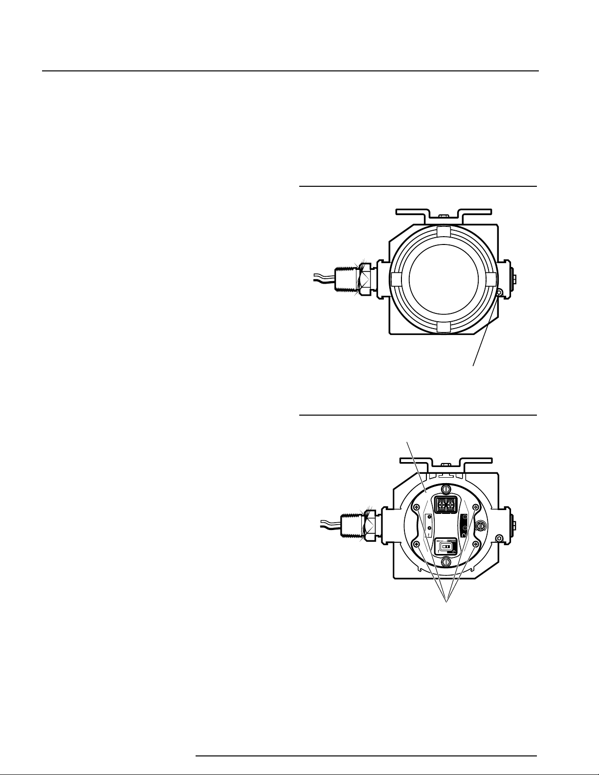
Locking screw
IPX
2
SELECTABLE OUTPUT
PS (+) PS (-)
ZERO
SPAN
ZERO
SPAN
Mounting screws
Electronic module
IPH
Current-to-Pressure
(I/P) Transmitters
&
2
IPX
Troubleshooting
the IPH2 & IPX2
If a problem is suspected with the IPH2 or IPX2, review
the following steps:
1. Verify that bench instruments used to take
measurements have the proper range and
accuracy and are within current certication period
limits.
2. If a change in the relationship between the input
and output is detected, attempt a re-calibration of
the unit.
3. If the response time lengthens, or if the span
drops, check the system for a blockage due
to air supply contamination. Please refer to
Maintenance section for details of replacing lters,
electronic modules and drain checking.
If the unit needs to be returned for service, the
complete valve assembly can be removed from
the housing for replacement without disturbing the
connections to the housing. Contact customer service
for details.
the recovery of the unit, by allowing any accumulated
liquid to drain out more eectively. To remove the
module follow these steps:
1. Use a 3mm Allen wrench to unlock the cover.
Drive the Allen screws clockwise until the cover
is allowed to rotate freely. Remove the cover by
accessing the locking screw shown in Figure 6.
Figure 6. Unlocking the IPX 2 Cover
2. Use a Phillips head screw driver to remove the
four module mounting screws shown in Figure 7.
Drain Check
System lters (not IPX2/IPH2 lters) have automatic
drains that depend on the uctuation of system
pressure to induce drainage. A stable system may not
drain eciently. Check periodically for clogs and drain
system’s lters by pushing the drainage valve with a
small probe or wire.
IPX2 Replacement Modules*
*This applies only to new versions of the IPX2
introduced in 2013.
In abnormal operating conditions in which a slug
(liquid) is present in the IPX2 air/ gas supply, the
electronic module may be removed. This can help in
Figure 7. Removing Mounting Screws
3. Carefully, pull the module from the housing. The
pneumatic stem, found on the bottom of the
module, is fragile; handle with care. See Figure 8.
14 Demand Moore Reliability

IPH
2
&
IPX
2
Current-to-Pressure
(I/P) Transmitters
Figure 8. Removing Module from Housing
Item P/N Description Qty
1 208-876-00 Module 1
1
Barrier
plate
Customer Service
Moore Industries is recognized as the industry leader
in delivering top quality to its customers in products
and services. We perform a battery of stringent
quality assurance checks on every unit we ship. If any
Moore Industries product fails to perform up to rated
specications, call us for help. Our highly skilled sta
of trained technicians and engineers pride themselves
on their ability to provide timely, accurate and practical
answers to your process instrumentation questions.
Factory phone numbers are listed on the back cover of
this manual.
If problems involve a particular IPH2/IPX2, there are
several pieces of information that can be gathered
before you call the factory that will help our sta get
the answers you need in the shortest time possible.
For fastest service, gather the complete model and
serial number(s) of the problem unit(s) and the job
number of the original sale.
4. Inspect the module and the barrier plate for any
signs of contamination. Remove any excess liquid
and allow to dry before replacing. The electronic
module is not eld-serviceable. If irreparable
damage is found, it may be replaced. See Data
Sheet for ordering information.
5. To re-assemble, replace the module using locating
pins (see step 3), tighten the 4 module screws
(see step 2), replace the cover and secure with the
locking screw (step 1).
6. Recalibrate the unit before returning to service.
Refer to the Calibration Section of this manual for
instructions.
Demand Moore Reliability 15

2
IPH
Current-to-Pressure
(I/P) Transmitters
&
2
IPX
16 Demand Moore Reliability

IPH
2
&
IPX
2
Current-to-Pressure
(I/P) Transmitters
Demand Moore Reliability 17

2
IPH
Current-to-Pressure
(I/P) Transmitters
&
2
IPX
18 Demand Moore Reliability

RETURN PROCEDURES
United States • info@miinet.com
Tel: (818) 894-7111 • FAX: (818) 891-2816
Australia • sales@mooreind.com.au
Tel: (02) 8536-7200 • FAX: (02) 9525-7296
Belgium • info@mooreind.be
Tel: 03/448.10.18 • FAX: 03/440.17.97
The Netherlands • sales@mooreind.nl
Tel: (0)344-617971 • FAX: (0)344-615920
China • sales@mooreind.sh.cn
Tel: 86-21-62491499 • FAX: 86-21-62490635
United Kingdom • sales@mooreind.com
Tel: 01293 514488 • FAX: 01293 536852
To return equipment to Moore Industries for repair, follow these four steps:
1. Call Moore Industries and request a Returned Material Authorization (RMA) number.
Warranty Repair –
If you are unsure if your unit is still under warranty, we can use the unit’s serial number
to verify the warranty status for you over the phone. Be sure to include the RMA
number on all documentation.
Non-Warranty Repair –
If your unit is out of warranty, be prepared to give us a Purchase Order number when
you call. In most cases, we will be able to quote you the repair costs at that time.
The repair price you are quoted will be a “Not To Exceed” price, which means that the
actual repair costs may be less than the quote. Be sure to include the RMA number on
all documentation.
2. Provide us with the following documentation:
a) A note listing the symptoms that indicate the unit needs repair
b) Complete shipping information for return of the equipment after repair
c) The name and phone number of the person to contact if questions arise at the factory
3. Use sucient packing material and carefully pack the equipment in a sturdy shipping container.
4. Ship the equipment to the Moore Industries location nearest you.
The returned equipment will be inspected and tested at the factory. A Moore Industries
representative will contact the person designated on your documentation if more information is needed. The repaired equipment, or its replacement, will be returned to you in accordance with the shipping instructions furnished in your documentation.
WARRANTY DISCLAIMER
THE COMPANY MAKES NO EXPRESS, IMPLIED OR STATUTORY WARRANTIES (INCLUDING ANY WARRANTY OF MERCHANTABILITY OR
OF FITNESS FOR A PARTICULAR PURPOSE) WITH RESPECT TO ANY
GOODS OR SERVICES SOLD BY THE COMPANY. THE COMPANY DISCLAIMS ALL WARRANTIES ARISING FROM ANY COURSE OF DEALING
OR TRADE USAGE, AND ANY BUYER OF GOODS OR SERVICES FROM
THE COMPANY ACKNOWLEDGES THAT THERE ARE NO WARRANTIES
IMPLIED BY CUSTOM OR USAGE IN THE TRADE OF THE BUYER AND
OF THE COMPANY, AND THAT ANY PRIOR DEALINGS OF THE BUYER
WITH THE COMPANY DO NOT IMPLY THAT THE COMPANY WARRANTS
THE GOODS OR SERVICES IN ANY WAY.
ANY BUYER OF GOODS OR SERVICES FROM THE COMPANY
AGREES WITH THE COMPANY THAT THE SOLE AND EXCLUSIVE REMEDIES FOR BREACH OF ANY WARRANTY CONCERNING THE GOODS
OR SERVICES SHALL BE FOR THE COMPANY, AT ITS OPTION, TO
REPAIR OR REPLACE THE GOODS OR SERVICES OR REFUND THE
PURCHASE PRICE. THE COMPANY SHALL IN NO EVENT BE LIABLE
FOR ANY CONSEQUENTIAL OR INCIDENTAL DAMAGES EVEN IF THE
COMPANY FAILS IN ANY ATTEMPT TO REMEDY DEFECTS IN THE GOODS
OR SERVICES , BUT IN SUCH CASE THE BUYER SHALL BE ENTITLED
TO NO MORE THAN A REFUND OF ALL MONIES PAID TO THE COMPANY
BY THE BUYER FOR PURCHASE OF THE GOODS OR SERVICES.
ANY CAUSE OF ACTION FOR BREACH OF ANY WARRANTY BY
THE COMPANY SHALL BE BARRED UNLESS THE COMPANY RECEIVES FROM THE BUYER A WRITTEN NOTICE OF THE ALLEGED
DEFECT OR BREACH WITHIN TEN DAYS FROM THE EARLIEST DATE
ON WHICH THE BUYER COULD REASONABLY HAVE DISCOVERED
THE ALLEGED DEFECT OR BREACH, AND NO ACTION FOR THE
BREACH OF ANY WARRANTY SHALL BE COMMENCED BY THE
BUYER ANY LATER THAN TWELVE MONTHS FROM THE EARLIEST
DATE ON WHICH THE BUYER COULD REASONABLY HAVE DISCOVERED THE ALLEGED DEFECT OR BREACH.
RETURN POLICY
For a period of thirty-six (36) months from the date of shipment, and under
normal conditions of use and service, Moore Industries (“The Company”)
will at its option replace, repair or refund the purchase price for any of its
manufactured products found, upon return to the Company (transportation
charges prepaid and otherwise in accordance with the return procedures
established by The Company), to be defective in material or workmanship.
This policy extends to the original Buyer only and not to Buyer’s customers
or the users of Buyer’s products, unless Buyer is an engineering contractor
in which case the policy shall extend to Buyer’s immediate customer only.
This policy shall not apply if the product has been subject to alteration,
misuse, accident, neglect or improper application, installation, or operation.
THE COMPANY SHALL IN NO EVENT BE LIABLE FOR ANY INCIDENTAL
OR CONSEQUENTIAL DAMAGES.
Specications and Information subject to change without notice.© 2016 Moore Industries-International, Inc.
 Loading...