

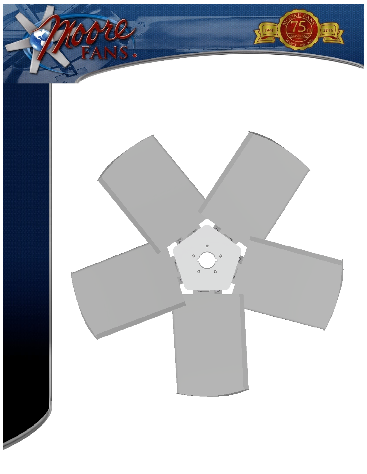
Class 10000 Heavy Duty
Series 12
Installation Instructions
MOORE FANS LLC, MARCELINE, MO 64658
TMC 911 REV A (JUN/17)
PHONE (660) 376-3575 FAX (660) 376- 2909
www.moorefans.com
EMAIL info@moorefans.com

INSTALL HUB AND AIR SEAL
Hub installation instructions:
The aluminum bushing is lubricated and pre-installed in the hub at the factory, no further lubrication is required prior to installation. DO NOT apply lubricant between the bushing bore and the shaft. Leave slight play between the bushing and hub to fa-
cilitate installation on the shaft. Place the hub/bushing on the shaft. Insert the key, and tighten the setscrew to secure the hub and
key to the shaft. Now begin sequentially tightening the socket head cap screws (approximately 2-3 turns per cap screw initially)
to firmly engage the bushing in the hub and seat the bushing on the shaft. Once the bushing/hub is firmly seated on the shaft,
continue tightening the cap screws sequentially until the specified torque of 50 FT-LBS (6.9 M-KG) is reached.
DO NOT over-tighten cap screws as this could cause damage to the hub.
FAN HUB
(grease on bushing bore taper)
BUSHING TAPER
(grease on this surface)
CAP SCREWS
(grease on threads and
underside of head)
BUSHING
Caution:
If bushing is expected to see frequent oscillating loads
(Greater than 50% of nominal expected Static Torque),
Fan should be operated for approximately 15 minutes
and then re-torque bushing cap screws.
INSTALL AND ADJUST BLADES
BLADE
ROD END
BLADE BOLT
NOTE: MOUNTING BOLT
SUPPLIED WITH GREASE ON
THREADS AND CONICAL FACE
BEFORE INSTALLING BLADES. . . .
Check to see that the hub is level. If the drive shaft is not truly vertical,
causing the hub to be cocked, it will be difficult to adjust blade angles
accurately. Eccentric rotation of the fan can also cause serious vibration
problems. If misalignment, vibration or unbalance in the system is present, it
will be more easily identified and corrected at this time.
Moore fan blades are carefully balanced to the same moment at
the factory.
Proper installation, with particular attention to
tightening bolts to the specified torque, is essential to
maintain the design integrity of these units.
Install one blade: Clean any dirt or grease from the rod
end and the surfaces of the mounts. Align the rod end hole with
the holes in the mounts and insert the blade mounting bolt first
through the mount with the recess to accept the bolt head, then
through the rod end hole and screw the bolt into the second
mount lightly. The blade mounting bolt is supplied from the
factory with grease on the threads and conical face. Do NOT
clean the grease from the bolt.
Complete the installation of one blade by holding
the blade so that the blade extends straight out from the rod
end. Holding the blade in this position, tighten the bolt
using a torque wrench set to 200 ft-lb (27.6 m-kg) making
sure the rod end and the mounts seat.
After installing the first blade, manually rotate the fan
to be sure the blade clears the ring or throat at all points. When
the blade is held in alignment with the rod end (that is, straight
outward from the hub), it should clear the fan ring by a
distance adequate to provide for any relative motion between
the fan wheel and the ring. Excess clearance between the blade
tips and the ring, however, should be avoided to prevent
backflow which seriously reduces fan efficiency. If clearance
is excessive, the diameter may be adjusted at this time.
Install the remaining blades so that they are identical
with the first blade. Torque all bolts to 200 ft-lbs (27.6 m-
kg).
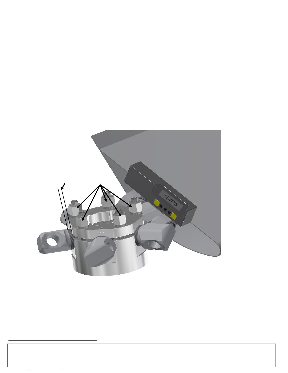
.25” MAX Clamp Bolts
Hubs are shipped from the factory with the rod end set for the blade angle indicated by the design performance. A change in blade
angle is sometimes necessary, however, to adjust to actual site conditions. Failure to adjust the blade angle when required may
result in blade or motor overload.
To adjust, loosen the Clamp Bolts just enough to allow the blade to be turned. Place an inclinometer on the flat surface of
the root section as shown in the illustration above. Turn the blade until the desired angle is achieved.. Make a permanent record
of the final angle selected and take care that all blades on the fan are set at the same angle. A typical adjustment may be +/- 3°
from design angle (+/- .5° tolerance blade to blade). The maximum recommended blade angle is 30°. Please consult the
factory if it is desired to go above this.
Retighten the Clamp Bolts To 60 FT-LBS (8.3 M-KG).
Recheck each blade angle after tightening.
WARNING: The fan is designed to consume the horsepower stated on the Fan Specification Sheet. Too great an increase in
blade angle can cause serious blade overload which will stall the blades. In this condition, the fan will actually deliver less air
and blade life may be shortened.
ADJUST DIAMETER IF REQUIRED
At times it may be necessary to adjust the fan diameter to
suit a particular ring. To do so, loosen the clamp bolts so
that the rod end can be rotated in the clamp block. One
complete revolution will increase or decrease the radius of
the fan by 1.5 mm (.06 in). Take care that the blade is
returned to exactly the factory-set angle unless it is intended
that the blade loading be
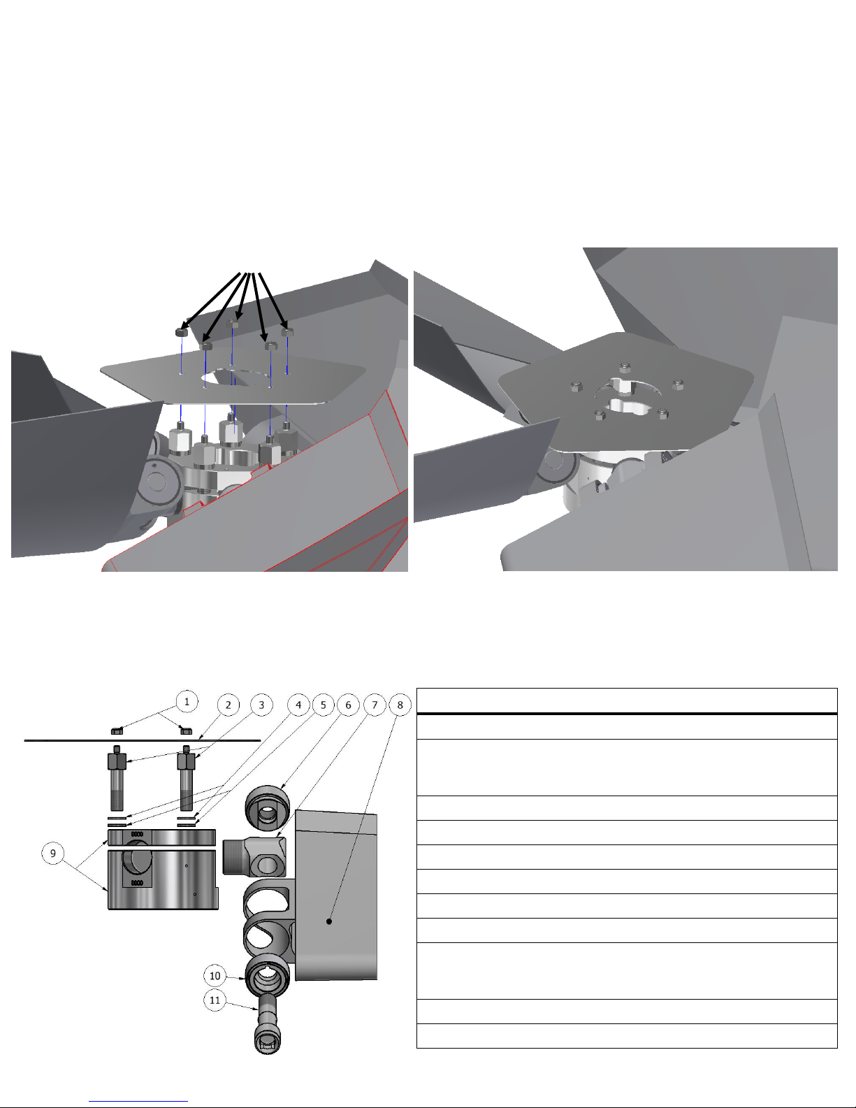
INSTALL AIR SEAL
AIR SEAL NUTS
changed as discussed in the previous section. A match mark
may be made at a point on the threads and the clamp block
before turning to assure that exactly one revolution is made.
Tighten the clamp bolts to 60 FT-LBS. Maximum adjustment
possible is +0" -.25” (6.35 mm) radially (.5” on diameter). No
more than .25" (6.35 mm) of rod end threads can remain
outside the clamp block.
**Fans with ATEX tips do not have any inward diameter
adjustment.
To install an air seal:
Align notches in air seal with bushing bolts and place
on to mounting studs.
Carefully tighten lock nuts to 50 lb-in (5.6 N-m)
PARTS LIST
ITEM PART # DESCRIPTION
1
2
3
4
5
6
7
8
9
P5122 LOCKNUT
P114
P117
P118
P7110 CLAMP BOLT
P1501 LOCK WASHER
P120 FLAT WASHER
P271 THREADED MOUNT
P7109 ROD END
CONTACT SALES FAN BLADE
P1144
P1152
P1153
3 BLADE AIRSEAL
4 BLADE AIRSEAL
5 BLADE AIRSEAL
3 BLADE HUB
4 BLADE HUB
5 BLADE HUB
MOORE FANS LLC, MARCELINE, MO 64658
TMC 911 REV A (JUN/17)
10
11
PHONE (660) 376-3575 FAX (660) 376- 2909
www.moorefans.com
P272 BORED MOUNT
P119 BLADE BOLT
EMAIL info@moorefans.com
 Loading...