

Page 1
TM
Visionary Boards
Assembly Instructions
1
Page 2
EVisionary Board with Aluminum Tray
TM
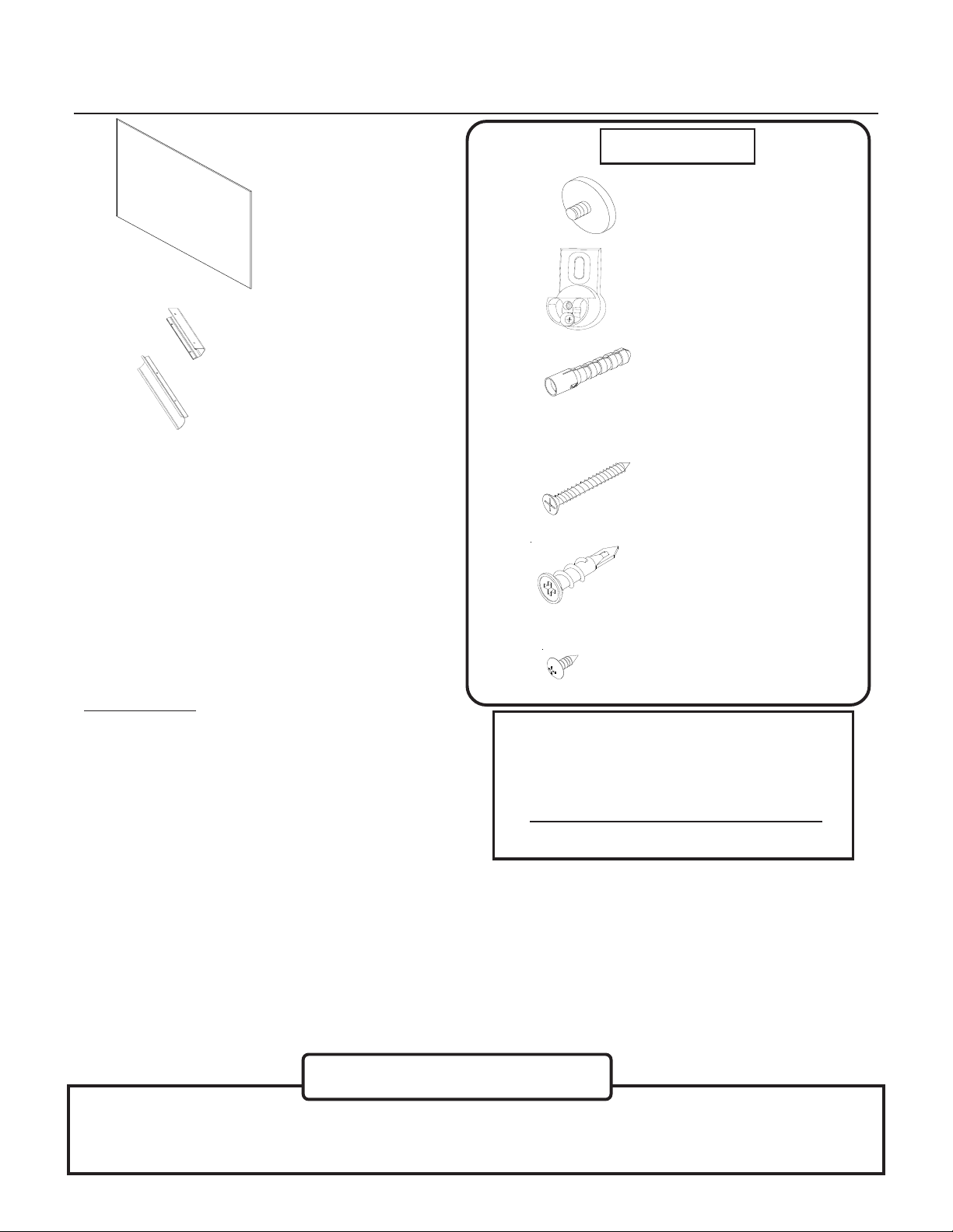
Part Drawing Description Qty
P-1 Glass Board 1 EA
P-2
P-3 Aluminum Tray 1 EA
Tray Mount 1 EA
Part Drawing Description Qty
Hardware List
A Outer Cap
B Wall Mount
C Plastic Anchor
D CS Screw
WARNING
Visionary Boards are made of Safety
Glass, but the improper handling and
installation may cause serious injury
if the board shatters. .
SPECIAL NOTE:
Make sure your wall is flat. On sheetrock and stud walls,
always try to hit studs if possible. I minimum of 1/2”
sheetrock is required. Use the correct diameter predrill
for the type anchor you are using.
E Drywall Anchor
F Phillips T ray Screw
Missing Parts or UPS Damaged Parts
For Your Convenience you can
EMAIL us at
24HOURS 7 DA YS A WEEK
Important Information
Do not use unless all screws are tight. At least every six months, check all screws to be sure
they are tight. If parts are missing, broken, damaged, or worn, stop use of the product until
repairs are made by your dealer using factory authorized parts.
2
Page 3
TM
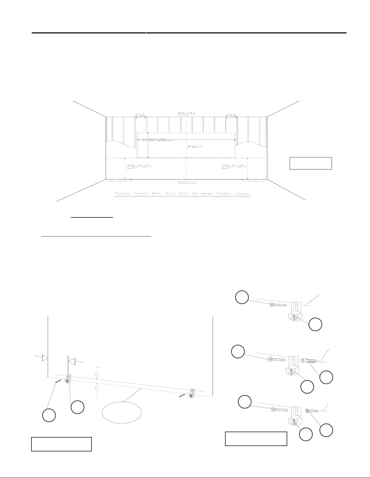
a.) Determine the type wall you are mounting your new board on.
b.) Measure the length, width and center lines of your board and your wall. Determine the height off
the floor that you want the bottom of your board. Most boards are mounted about 36” off the floor .
c.) With help, hold your board up in position and draw a line around the perimeter. Make sure these
drawn lines are parallel with the ceiling and floor . . .
d.) If your wall has studs, it is recommended that you mount into as many studs as possible.
illustration # 1
NOTE: The proper installation of your board will require at least two people.
T ools required: T ape measure, chalkline, electric drill / screwdriver , drill and
screwdriver bits, stud finder and level. .
To Assemble and Attach to Wall:
Identify and Separate all the Parts and Hardware.
1.)
2.) Pick the correct type of mounting hardware and anchors for your type wall .
3.) Measure up 1 1/4” above the bottom line and draw another line that is parallel. Measure in
about 6” from each side and install your bottom Wall Mount s (B) as shown in illustrations #2
and Detail #2a. The W all Mounts (B) should be placed on 16” centers as a minimum and
not more than 24” as a maxium. .
D
1/8” Predrill
Stud W all
B
D
1/4” Predrill
6”
1 1/4”
Masonary Wall
B
C
B
D
illustration # 2
Board
Outline
D
1/4” Predrill
Sheet Rock Wall
F
Detail # 2a
B
3
Page 4
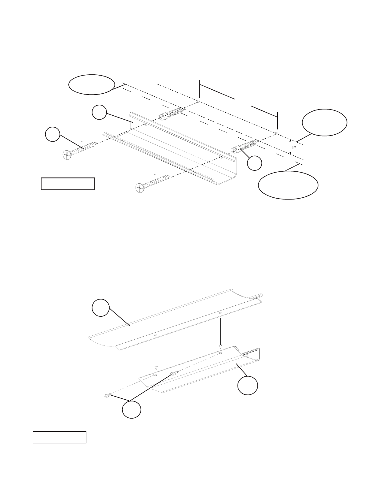
4.) Determine where you want your tray to be located and mark a line 1” above the
bottom edge of your board. Drill two 5/16” diameter holes in the wall 5 3/4” apart.
Bottom of
Board
5 3/4”
P2
D
C
Tray Mount
Line
Illustration #3
Push in two Plastic Anchors (C) into the predrilled holes. Place the Tray Mount (P-2) over the
5.)
Plastic Anchors (C) and secure with two CS Screws (D) as shown in Illustration #3.
6.)
Place the Aluminum Tray (P-3) in the front slot of the Tray Mount (P-2) and align the holes.
Secure the Aluminum Tray (P-3) to the Tray Mount (P-2) using two Phillips Tray Screws (F).
See Illustration #4. .
P3
Line for Board
Mounts
Illustration #4
P2
F
4
Page 5
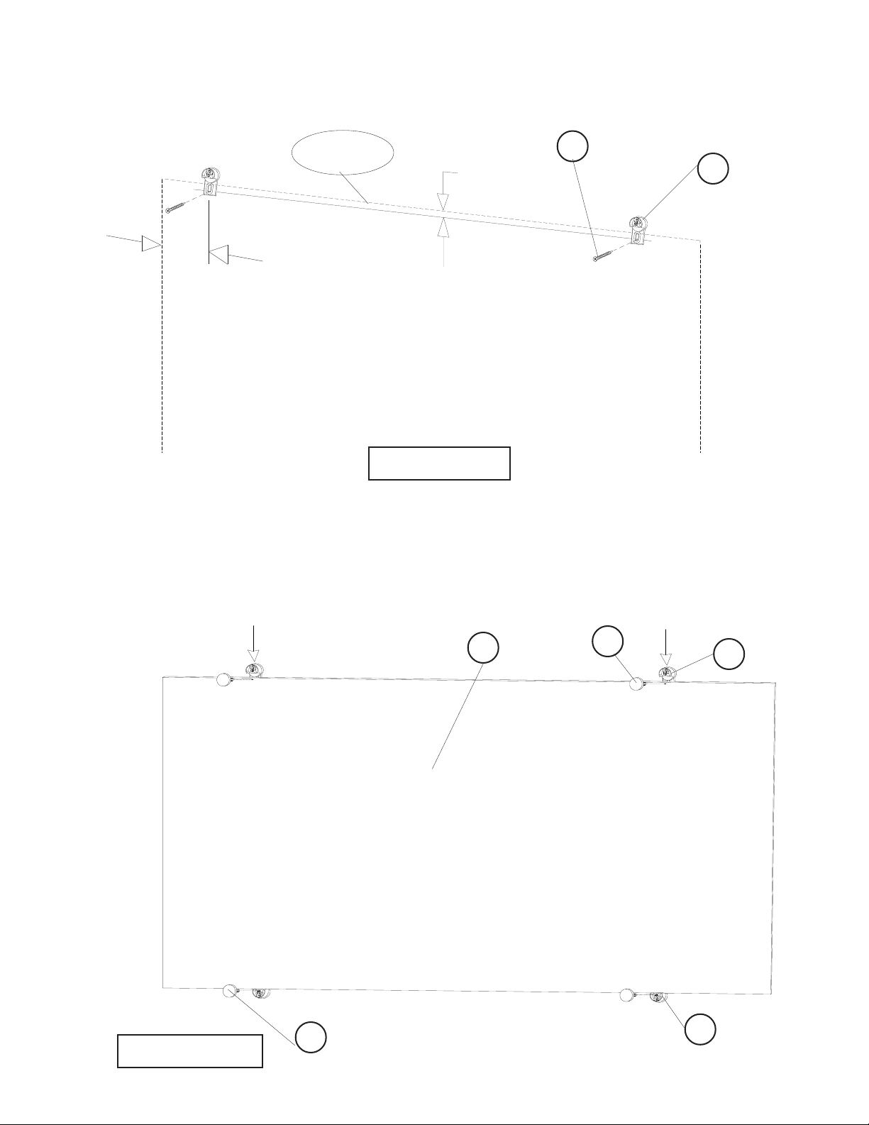
7.)
Measure down 3/4” from the top line and draw another line that is parallel. Measure in about
6” from each side and install your top Wall Mount s (B). Leave the top Wall Mounts pushed up
as shown in illustration #5. .
Top Edge
3/4”
D
B
6”
illustration # 5
8.) Place the Glass Board (P1) on the bottom Wall Mounts (B) and screw in the Outer Cap s (A) to
secure. Tilt the Glass Board back and push down the top W all Mounts (B) onto the board’s top
edge. Secure board in place by screwing in the top Outer Caps (A) as shown in illustration #6.
illustration # 6
A
P1
A
B
B
Visionary_3-6-14
5
 Loading...