

Page 1
March 2014
225-740-00G
HART® Concentrator System
HART-to-MODBUS RTU Converter
HCS
Concentrator System
®
HART
HART-to-MODBUS RTU Converter
HCS
Page 2

Table of Contents
Introduction ............................................................................................................................................. 4
About this Manual ............................................................................................................ 4
The HCS .......................................................................................................... 4
Model and Serial Numbers............................................................................................... 4
Inputs ............................................................................................................................... 4
Outputs ............................................................................................................................. 4
TX Power Supply .............................................................................................................. 4
Specifications ................................................................................................. 5
Dimensions ...................................................................................................................... 6
Terminal Designation Table .............................................................................................. 6
Hooking-Up the HCS Using the TX Power Supply .......................................................... 7
Hooking-Up the HCS Using an External Power Supply ...................................................8
HCS PC Hook-Up Diagram ............................................................................. 9
Factory Default Configuration ....................................................................... 9
Configuring the HCS .................................................................................... 10
Installing the Configuration Software .............................................................................10
Connecting the HCS to the PC ...................................................................................... 10
Selecting Model Type ..................................................................................................... 10
Necessary Equipment Table ........................................................................................... 10
PC Configuration Software Summary ........................................................ 11
Menu and Tool Bar Legend ........................................................................................... 12
Page 3

Configuration Screens ................................................................................. 12
HART .............................................................................................................................12
MODBUS ....................................................................................................................... 13
HART Devices ................................................................................................................ 15
Status of HART Devices ................................................................................................. 15
MODBUS Register Definitions ..................................................................... 16
HART Status Information ............................................................................. 25
Installation ..................................................................................................... 26
Mounting the HCS .......................................................................................................... 26
Making the Electrical Connections ................................................................................. 26
Recommended Ground Wiring Practices ....................................................................... 26
CE Conformity ................................................................................................................ 26
Power Sourcing Parameters for General Locations, Intrinsically Safe and
Non-Incendive/Type N Applications ............................................................................... 26
Operation ....................................................................................................... 27
Maintenance ................................................................................................................... 27
Customer Support ........................................................................................ 27
Appendix A: HCS Legacy Configuration ....................................................A1
Appendix B: HCS Legacy Configuration ....................................................B1
Page 4

HCS
HART® Concentrator System
HART-to-MODBUS RTU Converter
Introduction
This is the user’s manual for the Moore Industries
HCS HART® Concentrator System. It contains all of
the information needed to configure, install, operate
and maintain this instrument.
About this Manual
Pay particular attention wherever you see a “Note”,
“Caution” or “WARNING ”.
Note– Information that is helpful for a procedure, condition or operation of the unit.
Caution– Hazardous procedure or condition that
could damage or destroy the unit.
WARNING– Hazardous procedure or condition that
could injure the operator.
The HCS
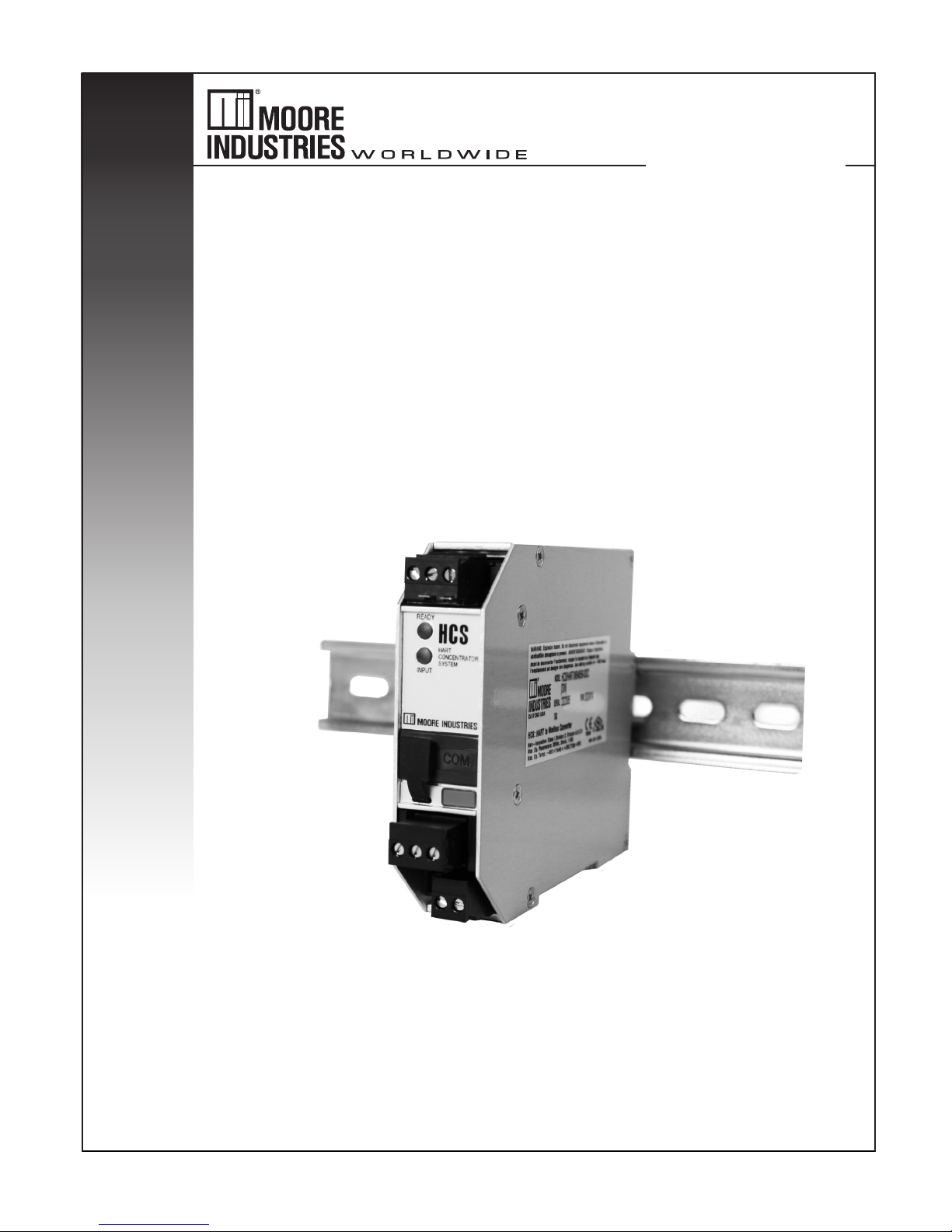
The HCS HART® Concentrator System converts
a HART digital signal to a serial MODBUS RTU
(RS-485 or RS-232, depending on Output type
ordered) communication protocol. This allows HART
transmitters and valves to interface directly with
MODBUS-based monitoring and control systems.
The HCS uses the following HART commands to
collect its data.
Command 0 Read transmitter unique identifier
Command 3 Read all dynamic variables and current
Command 13 Read tag, descriptor, date
Command 48 Read additional transmitter status
The 3rd generation HCS is now compatible with HART
7 protocol by the release of new HCS firmware v5.2.
This version of the HCS is compatible with HART
5, 6 and 7, however it does not support ALL of the
new features available in HART 6 and 7. Appendix
B provides more details of HART compatibility for all
generations of HCS.
Model and Serial Numbers
Moore Industries uses the model and serial numbers
of our instruments to track information on each unit
that we sell and service. If a problem occurs with
your HCS, check for a tag affixed to the unit listing
these numbers. Supply the Customer Support
representative with this information when calling.
Inputs
The HCS is equipped with one input channel. This
handles up to 16 HART devices in multidrop mode.
In a digital multidrop HART network, up to 16 HART
instruments digitally communicate on the same wires.
The HCS can be set to monitor any or all instruments
and/or valves within the network. Only one MODBUS
address and one communication link is needed to
send the process and diagnostic data from up to 16
HART devices to a MODBUS host.
The instrument is equipped with a READY LED to
indicate the health of the unit and an INPUT LED
to indicate status of HART communication to the
attached HART devices.
Outputs
The HCS offers a standard RS-485 or RS-232 port
(depending on Output type ordered) that supports the
MODBUS RTU protocol.
MB232
Allows for standard MODBUS RTU protocol interface
over a RS-232 port.
MB485
Allows for standard MODBUS RTU protocol interface
over a RS-485 port.
4 The Interface Solution Experts
TX Power Supply
A transmitter excitation power supply (regulated
23.2Vdc ±3%@24mA, maximum) is standard on the
HCS. You may access it at the terminals shown in
Figure 3.
* HART is a registered trademark of the HART Communication Foundation
Page 5

Specifications
HCS
HART® Concentrator System
HART-to-MODBUS RTU Converter
Performance
Input Accuracy: Reflects the
accuracy of the HART field
device
Input Impedance: Transmit
Mode: 150 ohms;
Receive Mode: Less than
5kohms
Isolation: 1000Vrms
between case, input, output
and power terminals and
will withstand 1500Vac
dielectric strength test for one
minute continuous with no
breakdown
Power Supply: 9-30DC
+TX Power Supply: 23.2Vdc
±3%@24mA
Digital Response Time:
Equals the combination of
the HART response time and
the MODBUS response time;
the HART delay is defined
by the HART protocol as
500msec in normal mode
and 333msec in burst mode;
the MODBUS response time
depends on how fast and
how often a MODBUS Master
requests data from the HCS;
the data request to response
time is 50msec
Output Type: Standard
MODBUS RTU protocol
interface over RS-485
(parameters as specified in
U.S. Standard EIA-RS485)
or RS-232 (parameters as
specified in U.S. Standard
EIA-RS232)
Output Protection:
Transient protection on output
Performance
(Continued)
Address Range:
Configurable from 1 to 247.
Unit will assume a MODBUS
address of 1 by default
Baud Rate: Interface
supports the following: 300,
600, 1200, 2400, 4800,
9600 and 19.2k. MODBUS
interface will support even,
odd and no parities. Unit will
assume a baud rate of 9600
and no parity by default
Transmission
Range (MB485): Using
24AWG twisted pair wiring,
maximum of 2 mi. (3.2km)@
4800 baud or less; maximum
of 1 mi. (1.6km)@9600 baud;
maximum of 0.5 mi. (0.8km)
@19200 baud
Character Format: One
start bit, 8 data bits and one
stop bit
Data Format: Userselectable Standard LSW
(Least Significant Word)
or Swapped MSW (Most
Significant Word). Unit will
assume Standard LSW by
default
Power Consumption:
1.5W, nominal; 2W@24Vdc
maximum for units using
transmitter excitation to
supply loop power to a
2-wire instrument
Indicators
Ambient
Conditions
Weight
LED Type: Dual color
red/green indicate:
INPUT LED: Input is present
and normal (green); input
signal is not found (red)
READY LED: Instrument
is ready for operation and
configuration (green);
instrument has encountered
an internal problem (red)
Operating and Storage
Range:
-40°C to +85°C
(-40°F to +185°F)
Relative Humidity:
0-95%, non-condensing
RFI/EMI Immunity
(Standard):
10V/m@80-1000MHz, 1kHz
AM, when tested according
to IEC61326
RFI/EMI Immunity
(with -RF Option):
20V/m@80-1000MHz, 1kHz,
when tested according to
IEC61326
Noise Rejection: Common
Mode: 100dB@50/60Hz
290 g (10.2 oz)
Specifications and information subject to change without notice.
The Interface Solution Experts 5
Page 6
HCS
100mm
(3.94 in)
52mm
(2.05 in)
48mm
(1.89 in)
C
L
WHEN INSTALLED
WHEN INSTALLED
25mm
(1.00 in)
151mm
(5.95 in)
146mm
(5.75 in)
139mm
(4.47 in)
COM
HCS
HART
Concentrator
System
READY
INPUT
®
HART® Concentrator System
HART-to-MODBUS RTU Converter
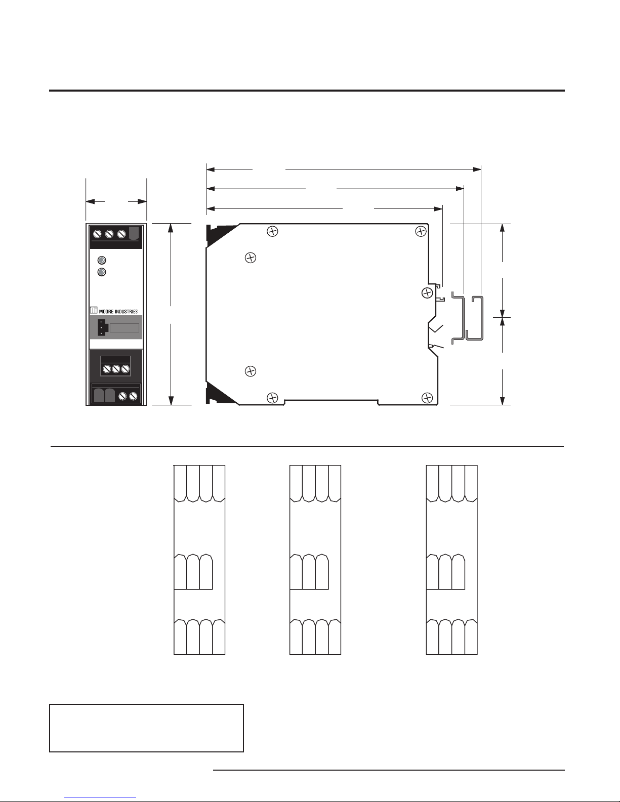
Figure 1. HCS Dimensions
Table 1. Terminal Designations
KEY:
+TX = Power for
2-Wire transmitter
+IN = Positive input
–IN = Negative input
-IN
+TX
+IN
1234
12
AB
1234
3
S
- DCC
+ DC
RS485
A = A MODBUS
B = B MODBUS
S = S MODBUS
(+) DC = Positive power input
(-) DCC = Negative power input
-IN
+TX
+IN
1234
TX RX
GND
1234
+ DC
- DCC
3
12
RS232
NOTE:
1. Terminal blocks can accommodate 14-22 AWG solid wiring.
2. Tighten terminals to four inch-pounds (maximum).
+TX
+IN
1234
12
RX/B
TX/A
1234
MB PRG
-IN
3
GND/S
+ DC
- DCC
6 The Interface Solution Experts
Page 7
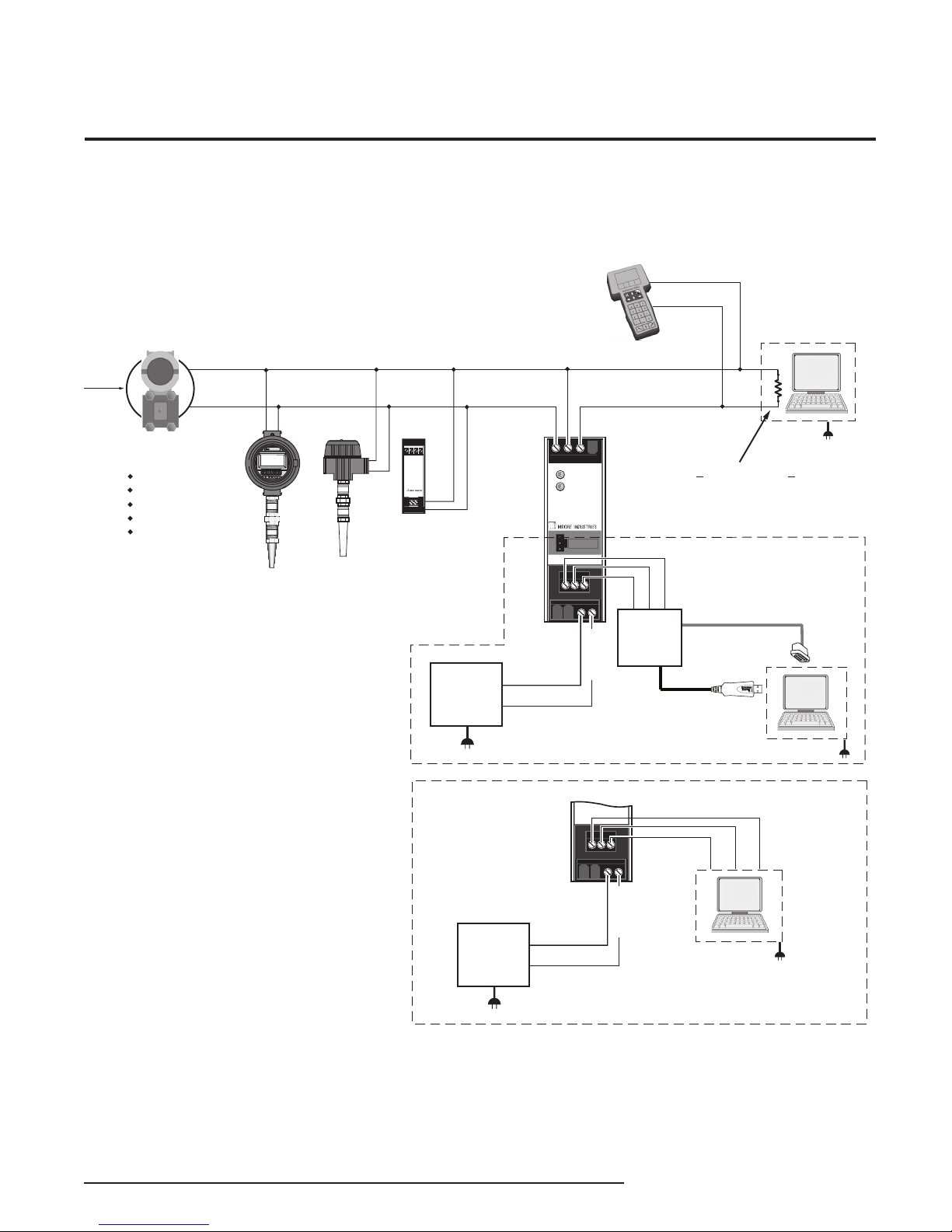
Figure 2. Installing the HCS Into the Loop Using the TX Power Supply to Power a Transmitter
+
–
+
–
+
–
THZ
(HART
Slave)
THZ
(HART
Slave)
TDZ
(HART
Slave)
+PS
-PS12
34
TDZ
ADDR
0
602.78
DEG C
DCS
Sensor
Input
–
+
R
HART
Field Instrument
+IN
+TX
–IN
COM
HCS
HART
Concentrator
System
READY
INPUT
®
Note: Refer to the TX Power Supply
specification to determine how many
instruments can be installed into your loop.
HART communicator can be
connected anywhere on the loop*
Temperature
Pressure
Level
Flow
Multivariable
R must be > 250 ohms and < 1100 ohms
1234
+PS –PS
THZ
SMART HART
TEMPERATURE
TRANSMITTER
(+) DC
9-30Vdc
Power
Source
(-) DCC
MODBUS
Output
A
B
S
To USB
(COM)
Port of PC
To serial
(COM)
Port of PC
or
MODBUS Host
RS-485/
RS-232
Converter
For RS-485 Output
MODBUS
Output
TX
RX
GND
MODBUS
Host
For RS-232 Output
OR
9-30Vdc
Power
Source
(Input wiring remains
the same as shown for
units equipped with
RS-485 output)
2
2
(+) DC
(-) DCC
* HCS units shipped since April 2014 provide test points on
the +IN & -IN terminals for connecting a HART communicator
HCS
HART® Concentrator System
HART-to-MODBUS RTU Converter
The Interface Solution Experts 7
Page 8
DCS
Sensor
Input
–
+
9-30Vdc
Power
Source
R
HART communicator can be
connected anywhere on the loop*
+IN
–IN
COM
HCS
HART
Concentrator
System
READY
INPUT
®
+
–
+
–
+
–
THZ
(HART
Slave)
THZ
(HART
Slave)
TDZ
(HART
Slave)
1234
+PS –PS
THZ
SMART HART
TEMPERATURE
TRANSMITTER
+PS
-PS12
34
TDZ
ADDR
0
602.78
DE G C
HART
Field Instrument
Temperature
Pressure
Level
Flow
Multivariable
24Vdc
Power
Source
+
–
MODBUS
Output
A
B
S
RS-485/
RS-232
Converter
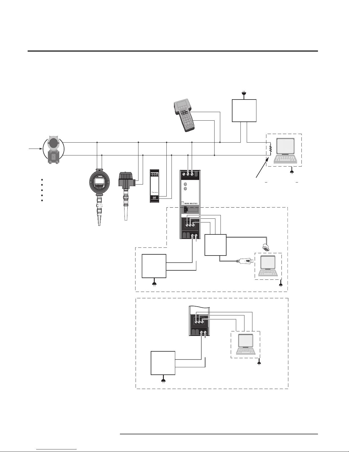
R must be > 250 ohms and < 1100 ohms
For RS-485 Output
MODBUS
Output
TX
RX
GND
MODBUS
Host
For RS-232 Output
OR
9-30Vdc
Power
Source
(Input wiring remains
the same as shown for
units equipped with
RS-485 output)
2
2
(+) DC
(-) DCC
(+) DC
(-) DCC
To USB
(COM)
Port of PC
To serial
(COM)
Port of PC
or
MODBUS Host
* HCS units shipped since April 2014 provide test points on
the +IN & -IN terminals for connecting a HART communicator
HCS
HART® Concentrator System
HART-to-MODBUS RTU Converter
Figure 3. Installing the HCS Into the Loop Using an External Power Source to Power a Transmitter
8 The Interface Solution Experts
Page 9
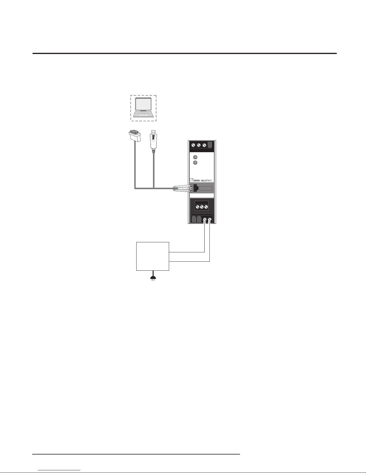
Figure 4. HCS PC Hook-Up Diagram
HCS
HART® Concentrator System
HART-to-MODBUS RTU Converter
PC
TO SERIAL
(COM) PORT
OF PC
To USB
(COM)
OR
Port of PC
9-30Vdc
Power
Source
Default Factory Configuration
for HCS
The following are the factory default configuration
settings for your HCS unit:
READY
INPUT
HCS
®
HART
Concentrator
System
COM
(+) DC
(-) DCC
HART Settings-
Polled HART Slave Devices: ........................1
HCS is a Primary Master
No of HART retries: ......................................1
MODBUS Settings-
Address: ........................................................1
Baud Rate:...............................................9600
MODBUS Parity:......................................None
MODBUS Float Format:............Standard LSW
MODBUS Register Layout:.....By Variable Type
MOBUS Failed HART Mode:.............Hold Last
Decimal Places:.............................................0
The Interface Solution Experts 9
Page 10
HCS
HART® Concentrator System
HART-to-MODBUS RTU Converter
Configuring the HCS
One of the benefits of the HCS is that there are no
internal or external controls to adjust or settings to
change. All operating parameters are set using the PC
Configuration software.
Once these software settings are made, they are
downloaded to the instrument in the form of a
Configuration File and stored in the unit’s nonvolatile
memory. You can choose to save a backup copy of
the file on your PC hard drive or external media. The
HCS communicates with the PC through a proprietary
communications cable to the PC’s serial (COM) port or
optional proprietary USB cable to the PC’s USB port.
Installing the Configuration Software
Refer to Table 2 for the equipment needed.
1. Insert the Moore Industries Interface Solution
PC Configuration Software CD into the CD
drive of the PC. Access the CD and open the
“HCS PC Configuration Software” folder.
2. Double-click the installation program located
in the folder. Follow the prompts to correctly
install the program.
Connecting the HCS to the PC
HCS can be connect to PC one of two ways:
• using the propr ietary communications cable to
connect to PC’s serial (COM) port
• using the optional proprietary USB cable to
connect to PC’s USB port
See Table 2 for information on the necessary
equipment.
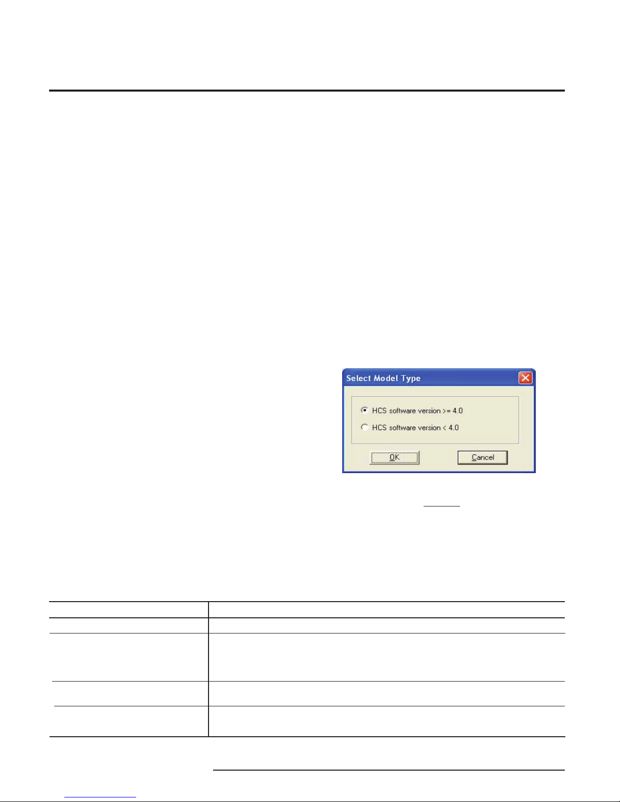
Selecting Model Type
User must select unit type when the software is
opened without a unit connected as shown below. Unit
type is determined by software version. When unit is
connected software will select the correct software on
automatically.
Once the Configuration Program is installed onto your
PC, the HCS can be connected into a system and
become operational.
Table 2. Necessary Equipment Table
Device Specifications
Power Supply
Personal Computer
Moore Industries
PC Configuration Software
Communication Cable
options
9-30DC, ±10%
Microsoft Windows based PC;
16Mb free RAM; 20MB free disk space on hard drive
Microsoft Windows XP, Vista or 7
1 (one) serial port or one available USB port
Version 1.0 or higher, successfully installed onto the hard drive
Serial Communications Cable (PN 803-053-26), USB Cable (PN 208-236-00) or
Fuse Protected USB Cable (PN 804-030-26)
Note:
The following information applies only to units
with software version 4.0 and greater, if you need
information pertaining to units with a software
less than 4.0 see Appendix A located at the end
of this manual
10 The Interface Solution Experts
Page 11
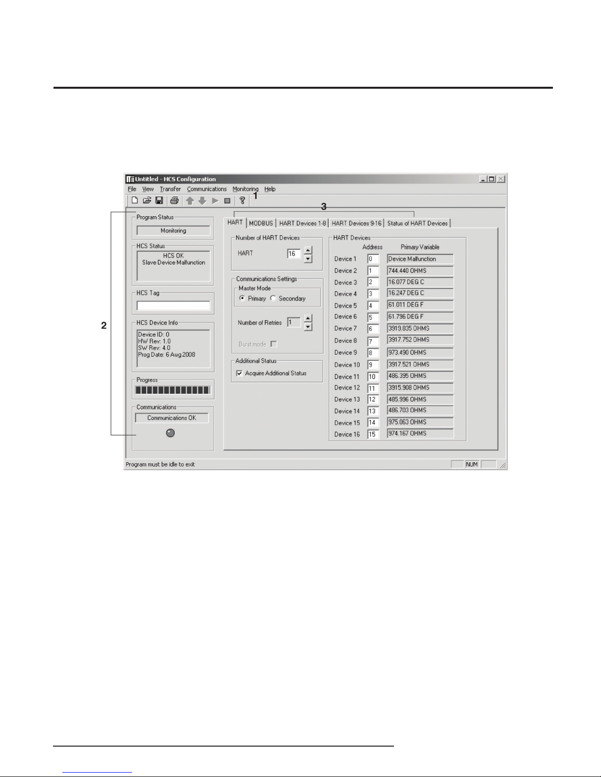
PC Configuration Software Summary
Figure 5. HCS PC Configuration Software Screen
HCS
HART® Concentrator System
HART-to-MODBUS RTU Converter
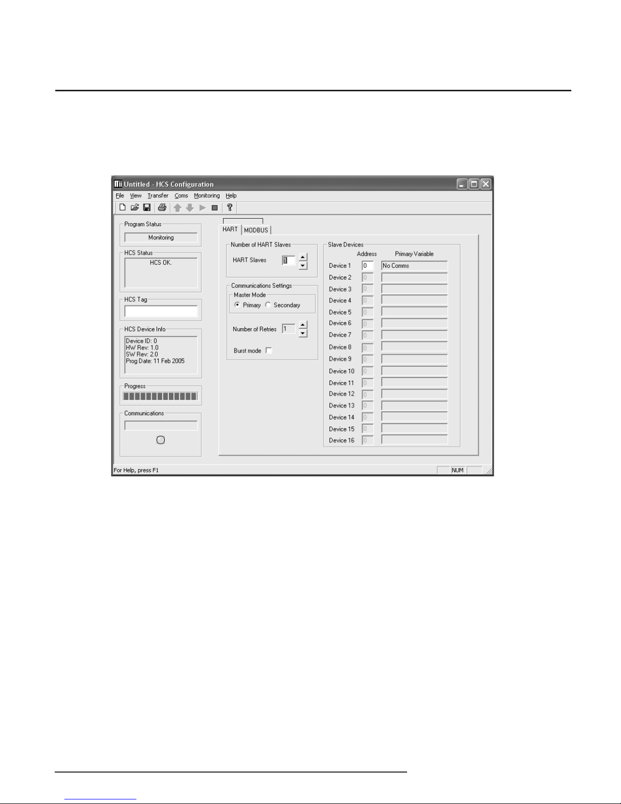
The HCS PC Configuration Software can be used to
program all of the instrument’s parameters. Once the
default configuration has been saved, it is safe to program other parameters.
The PC Software is composed of these sections:
1. Menu Bar/Tool Bar–Dropdown menus and corresponding icons allow you to perform various functions
throughout the PC Configuration Program. Refer to
the Menu and Tool Bar Legend section for a complete
description.
2. Program Status–This portion of the program displays the activity (idle, monitoring, downloading, uploading) of the connected unit.
HCS Status–Notifies of any errors or conditions which
are outside of the tolerance range. Displays HCS OK
if the unit is operating normally.
HCS Tag–A phrase used to identify an HCS (eight alphanumeric characters, maximum).
HCS Device Info–Displays the individual characteristics of the attached HCS, such as the device ID, hardware and software revisions and the last date that the
device was programmed.
Progress–This bar stays in motion any time the HCS
is monitoring, uploading or downloading, to notify that
a process is occurring.
Communications–Indicates current PC connection/
communications status.
3. HART/MODBUS/HART Devices/Status of HART
Devices Tabs–These tabs change the right side of the
screen to allow you to set the appropriate part of the
HCS’s configuration. See corresponding sections of
this manual for additional information on these tabs.
The Interface Solution Experts 11
Page 12
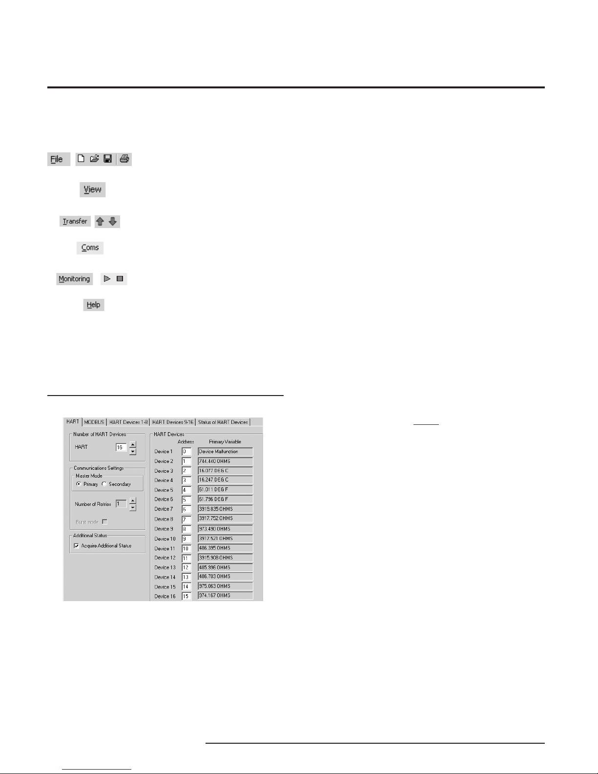
HCS
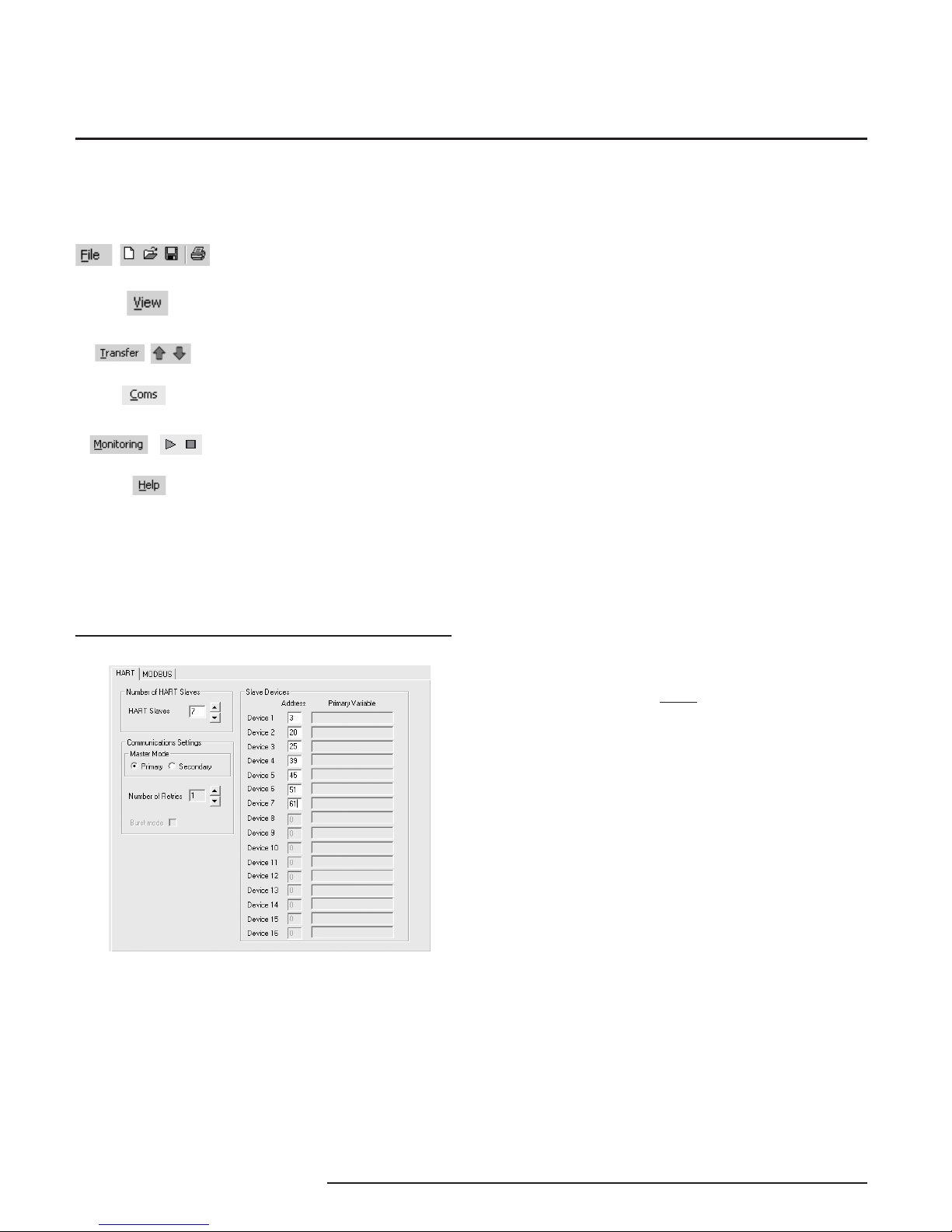
Allows such functions as New,
Open, Save and Print
Allows you to Upload and
Download configurations
Select the PC Port
(Com Port) that you will use
Allows you to Monitor and
Stop monitoring processes
Controls whether Tool and Status
Bars are viewed on the screen
Displays the version of the HCS
Configuration Program
HART® Concentrator System
HART-to-MODBUS RTU Converter
Menu and Tool Bar Legend
Configuration Screens
HART
Figure 6. HART Tab
Slave Devices
Once you have selected the number of HART slaves
to be used in the loop, use this section to assign a
specific address for each. Ensure that the address
matches the address of the device you connected in
the loop. Each must be a unique address between
zero and 63. However, Address 0 is an analog
address. Current readings at this address can vary
from 3.6mA to 23.6mA.
Master Mode
The HART protocol allows for two communications
masters on the loop: a Primary Master and a
Secondary Master. Setting the HCS to function as the
Primary HART Master in the application means that
any other HART device in the loop must be configured
either as a HART Secondary Master (1 per loop), or
as a HART Slave (up to 16 per loop). Conversely, setting the HCS to function as the Secondary HART Master allows other HART devices to function either as a
Primary Master, or as Slaves. Configuring more than
one device on a single loop as a Primary or Secondary HART Master will cause a communications failure.
Number of HART Devices
Using the up and down arrows, or by manually entering the value from your keyboard, select the number
of HART devices (16 maximum) that you will introduce
into your loop. The number you have chosen will
appear as enabled in the Slave Devices parameter.
Note:
A HART hand-held communicator is typically a
Secondary Master.
Number of Retries
The Number of Retries can be set between 1 and
3, and will determine how many times the HCS will
attempt to poll the HART transmitter (without success),
before it indicates a HART communication failure.
Burst Mode
Allows selection of Normal or Burst modes.
Burst mode can only be used with a single HART
device (slave).
The HCS can operate in one of two modes: Normal
or Burst. In each of these modes the HCS attempts to
find a HART transmitter. If the designated slave (or
slaves) is found, the HCS will also read the device’s
Tag.
12 The Interface Solution Experts
Page 13
HCS
HART® Concentrator System
HART-to-MODBUS RTU Converter
In Normal mode, the HCS polls the HART loop for a
transmitter, then polls the HART instrument twice per
second, requesting the current process status and
the HART instrument’s diagnostic status. The HART
instrument responds with the requested data.
In Burst mode, the monitored HART instrument
continuously transmits its process variable and health
status. The HCS samples the continuous HART data
three times per second.
The instrument will operate in Normal Mode by default.
Selecting the Burst Mode button will enable Burst
Mode reception in the HCS. An error is declared if no
burst messages are received by the HCS.
HCS Units with firmware version 4 or earlier will send
commands to the slave, configuring and enabling burst
mode.
HCS Units with firmware version 5 or later do not send
commands to configure the slave. The slave must be
configured (using a handheld configurator, or by other
means) to have burst mode enabled, and to burst
either HART command 1 or 3. If the HCS is able to
communicate with the slave but does not receive burst
messages, the Input LED will alternate red and green.
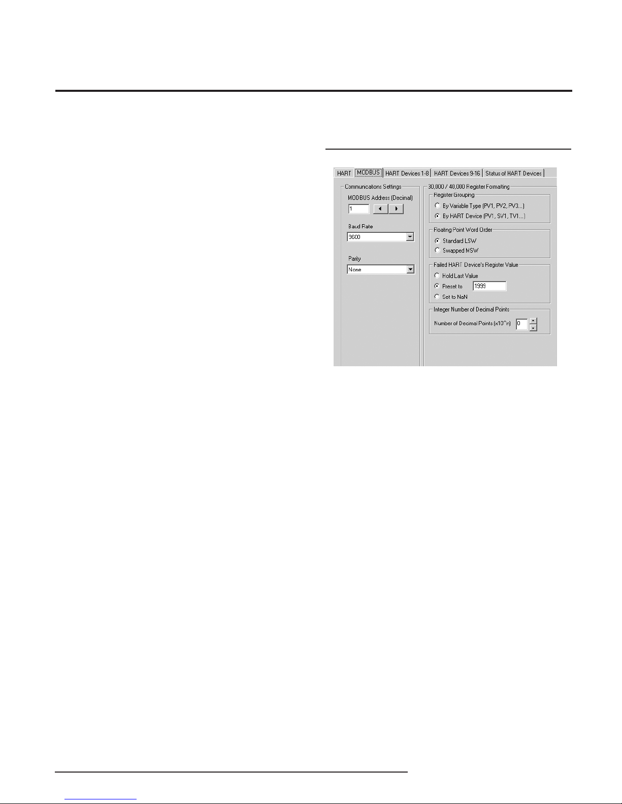
MODBUS
Figure 7. MODBUS Tab
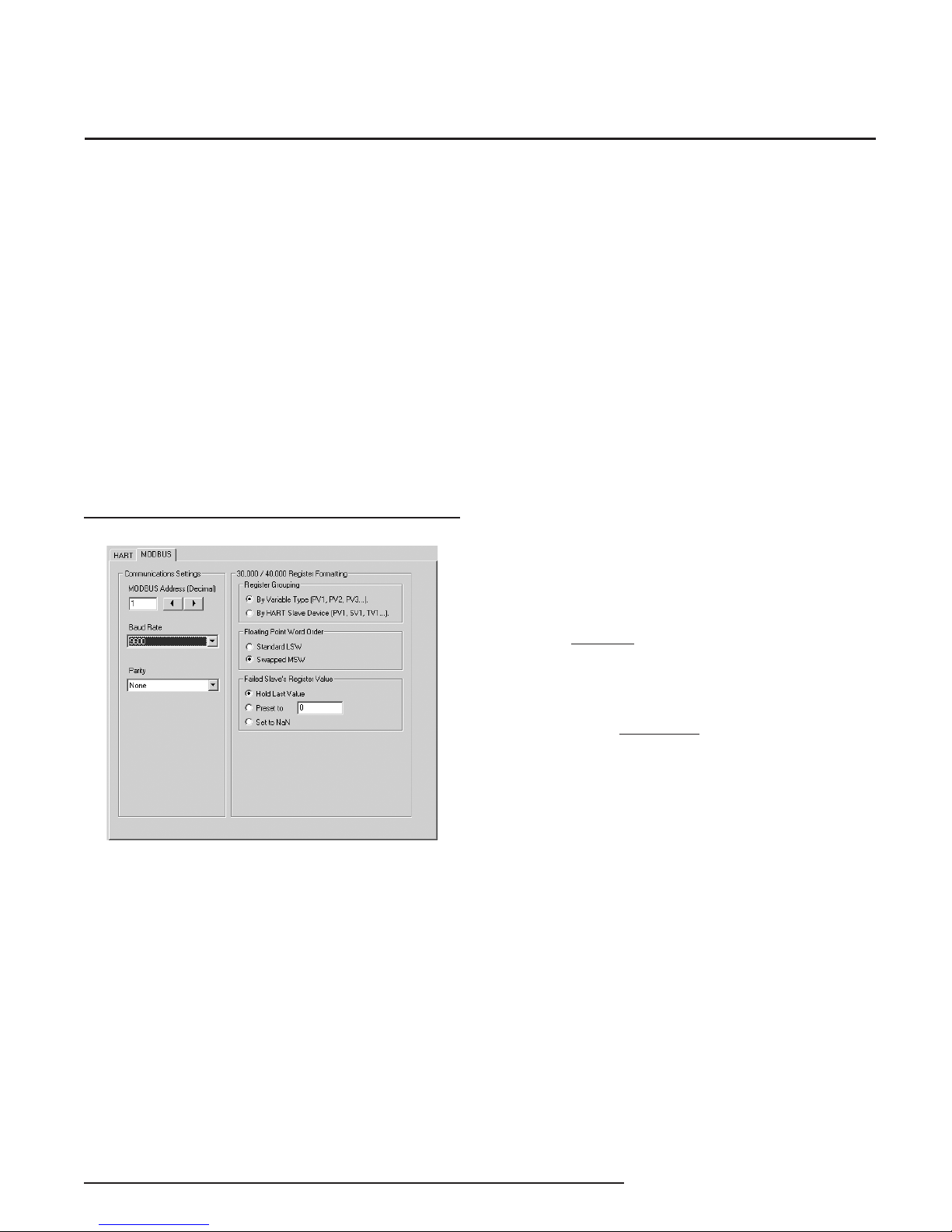
The MODBUS tab allows you to set the MODBUS
communications parameters.
Communications Settings
The Communications Settings include three areas:
Additional Status
Checking the Acquire Additional Status box will
allow Additional Status information to be displayed
on the Status of HART Devices screen and also in
the corresponding MODBUS register (refer to Tables
3 and 4). If the box remains unchecked, Additional
Status information will be unavailable.
For software version 5.0 and greater, all 25 additional
status bytes (0 to 24) are displayed and available in
Modbus registers 1000-1024 (see Tables 3.1 and 4.1)
If this information is not needed, it is good practice to
keep the box unchecked in order to keep polling of the
additional status bytes from occurring. This will help
maintain faster response times.
MODBUS Address (Decimal)
The MODBUS Address is the number that the HCS
monitor uses to identify itself on the MODBUS
network. The MODBUS address is configurable
from 1 to 247. By default, it will assume a MODBUS
address of 1.
Baud Rate
The Baud Rate is the speed of MODBUS data
transmission. It should be set to match the baud rate
of the attached controller. The interface supports the
following baud rates: 300, 600, 1200, 2400, 4800,
9600 and 19200.
Parity
The HART monitor supports even, odd and no Parity.
The data format is one start bit, 8 data bits and one
stop bit.
The Interface Solution Experts 13
Page 14
HCS
HART® Concentrator System
HART-to-MODBUS RTU Converter
30,000 / 40,000 Register Formatting
This section includes the following areas:
Register Grouping
This allows you to select the manner in which to group
the MODBUS registers.
Selecting By Variable Type, the registers are grouped
in order of variables, i.e. all primary variables (PV) are
grouped together, followed by secondary variables
(SV), third (TV) and then fourth (FV).
Using By HART Slave Device grouping places your
registers in order numerically. It groups a HART
slave device’s variables in contiguous registers. For
example, your first HART device’s primary, secondary,
third and fourth variables (PV1, SV1, TV1 and FV1)
are grouped together. Next in the order are your
second HART device’s primary, secondary, third and
fourth variables (PV2, SV2, TV2 and FV2) and so on.
Floating Point Word Order
By default, the HART Concentrator will use the
Standard LSW (least significant word) floating point
word order format. This stores the most significant
bits in the second register and the least significant bits
in the first register. Selecting Swapped MSW (most
significant word) will reverse the order, storing the
most significant bits in the first register and the least
significant bits in the second register.
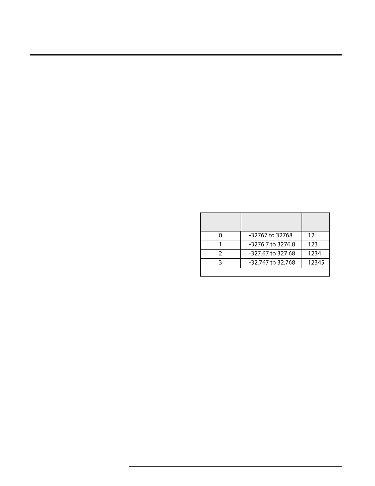
Integer Number of Decimal Points
The MODBUS integer registers are 16 bit signed
integers and have a range of -32767 to 32768.
To obtain better resolution, the “Integer Number of
Decimal Points” setting may be used. This can be set
from 0-3, and will multiply the PV by 10n where n is
the number of decimal points. Care should be taken in
selecting the resolution since the higher the resolution,
the smaller the PV range which can be represented
ie. for n=3 the maximum range is -32.767 to +32.768.
Depending on the nature of the data obtained from
the slave and the required resolution, this may be
unacceptable and in this case, floating point registers
should be used.
The table below shows the PV range for the selected
number of decimal points and a PV example.
Number of
Dceimals
Allowed PV Range
Example PV = 12.345
Displayed
Integer
Failed HART Device’s Register Value
You may select what would occur to a HART device’s
register value in the event that communication is lost
with the HCS.
If selecting Hold Last Value and a failure is detected,
the last measured value before the failure occurred is
held.
Entering a user-set value in the Preset to text box
recalls that value when a slave device failure is
detected.
Selecting NaN (Not a Number–as put forth by the
IEEE-754 standard) causes the floating point NaN
value to be stored in the registers used for holding
floating point values.
14 The Interface Solution Experts
Page 15
HCS
HART® Concentrator System
HART-to-MODBUS RTU Converter
HART Devices
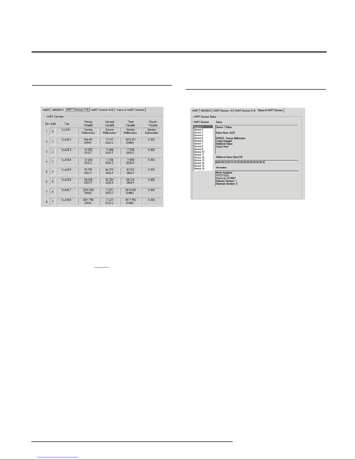
Figure 8. HART Devices Tabs
This following applies to both HART Device tabs (1-8
and 9-16).
These are read-only screens that display the device
number and its associated address, tag and the
Primary, Second, Third and Fourth variables.
Note:
This displays the 8 character Tag and not the 32
character Long Tag.
When the HCS is in Monitor mode, all four variables
constantly update. However, the Ta g only updates
once power is reapplied (upon a loss of power) or
when communication with the HART device has been
re-established.
Status of HART Devices
Figure 9. Status of HART Devices Tab
This screen displays Status the Additional Status and
Information regarding the selected device. Use the
HART Devices selection box to choose which device
to view.
For software version 4.0 and less only the first six
bytes (0-5) of additional status are available. For
software version 5.0 and greater, up to 25 additional
status bytes (0-24) are displayed and available in
Modbus registers 1000-1024 (see Tables 3.1 and 4.1).
The display will only show the additional status bytes
sent by the slave (from 0 to 25).
The Interface Solution Experts 15
Page 16

HCS
HART® Concentrator System
HART-to-MODBUS RTU Converter
MODBUS Register Definitions
Tables 3-6 define the MODBUS input and holding
register assignment. These tables are zero based,
your MODBUS host may require you to enter the
MODBUS register. Often registers have an offset
of “1” from the MODBUS address. For example, a
The following information applies only to units
with software version 4.0 and greater, if you need
information pertaining to units with a software less
than 4.0 see Appendix A located at the end of this
Note:
manual.
MODBUS address listed below of 256 may have to
be entered as 257 in your host. Please refer to your
MODBUS host documentation for verification.
Table 3. Register ranges and descriptions when MODBUS registers are grouped by the “By Variable Type” parameter
(MODBUS register block mode = 0) and all dynamic variables are being stored
Register
Description
Range
0-15
16-31
32-47
48-63
64-79
80-95
96-111
127
256-287
288-319
320-351
352-383
512-517
518-523
524-529
530-535
536-541
542-547
548-553
554-559
560-565
566-571
572-577
578-583
584-589
590-595
596-601
602-607
KEY:
FV = Fourth Variable
LSB = Least Significant Bit
MSB = Most Significant Bit
PV = Primary Variable
HART Device 1-16 PV integer value x 10^no of DPs
HART Device 1-16 SV integer value x 10^no of DPs
HART Device 1-16 TV integer value x 10^no of DPs
HART Device 1-16 FV integer value x 10^no of DPs
HART Device 1-16 HART Status
HART Device 1-16 PV + SV UOM (PV UOM = MSB, SV UOM = LSB)
HART Device 1-16 TV + FV UOM (TV UOM = MSB, FV UOM = LSB)
HCS Status
HART Device 1-16 PV floating point value stored in 2x16-bit registers per float
HART Device 1-16 SV floating point value stored in 2x16-bit registers per float
HART Device 1-16 TV floating point value stored in 2x16-bit registers per float
HART Device 1-16 FV floating point value stored in 2x16-bit registers per float
HART Device 1 additional status byte 0 to byte 5
HART Device 2 additional status byte 0 to byte 5
HART Device 3 additional status byte 0 to byte 5
HART Device 4 additional status byte 0 to byte 5
HART Device 5 additional status byte 0 to byte 5
HART Device 6 additional status byte 0 to byte 5
HART Device 7 additional status byte 0 to byte 5
HART Device 8 additional status byte 0 to byte 5
HART Device 9 additional status byte 0 to byte 5
HART Device 10 additional status byte 0 to byte 5
HART Device 11 additional status byte 0 to byte 5
HART Device 12 additional status byte 0 to byte 5
HART Device 13 additional status byte 0 to byte 5
HART Device 14 additional status byte 0 to byte 5
HART Device 15 additional status byte 0 to byte 5
HART Device 16 additional status byte 0 to byte 5
SV = Secondary Variable
TV = Third Variable
*UOM = Unit of Measurement
*Moore Industries provides up to 169 HART Engineering Units listed in HART
Communication Foundation document number: HCF-SPEC-183, Revision 14.0, Release
Date 29 January 2004
16 The Interface Solution Experts
Page 17

Table 3.1. Additional status byte 0 to byte 24 (for software version 5.0 and greater).
HCS
HART® Concentrator System
HART-to-MODBUS RTU Converter
Register
Range
1000-1024
1025-1049
1050-1074
1075-1099
1100-1124
1125-1149
1150-1174
1175-1199
1200-1224
1225-1249
1250-1274
1275-1299
1300-1324
1325-1349
1350-1374
1375-1399
Description
HART Device 1 additional status byte 0 to byte 24
HART Device 2 additional status byte 0 to byte 24
HART Device 3 additional status byte 0 to byte 24
HART Device 4 additional status byte 0 to byte 24
HART Device 5 additional status byte 0 to byte 24
HART Device 6 additional status byte 0 to byte 24
HART Device 7 additional status byte 0 to byte 24
HART Device 8 additional status byte 0 to byte 24
HART Device 9 additional status byte 0 to byte 24
HART Device 10 additional status byte 0 to byte 24
HART Device 11 additional status byte 0 to byte 24
HART Device 12 additional status byte 0 to byte 24
HART Device 13 additional status byte 0 to byte 24
HART Device 14 additional status byte 0 to byte 24
HART Device 15 additional status byte 0 to byte 24
HART Device 16 additional status byte 0 to byte 24
The Interface Solution Experts 17
Page 18

HCS
HART® Concentrator System
HART-to-MODBUS RTU Converter
Table 4. Register ranges and descriptions when MODBUS registers are grouped by the “By HART Slave Device” parameter
(MODBUS register block mode = 0) and PV, SV, TV and FV are being stored
Register
Range
0
1
2
3
4
5
6
7
8
9
10
11
12
13
14
15
16
17
18
19
20
21
22
23
24
25
26
27
28
29
30
31
32
33
34
35
36
37
Description
HART Device 1 PV integer value x 10^no of DPs
HART Device 1 SV integer value x 10^no of DPs
HART Device 1 TV integer value x 10^no of DPs
HART Device 1 FV integer value x 10^no of DPs
HART Device 1 HART Status
HART Device 1 PV & SV UOM (PV UOM = MSB, SV UOM = LSB)
HART Device 1 TV & FV UOM (TV UOM = MSB, FV UOM = LSB)
Not assigned
HART Device 2 PV integer value x 10^no of DPs
HART Device 2 SV integer value x 10^no of DPs
HART Device 2 TV integer value x 10^no of DPs
HART Device 2 FV integer value x 10^no of DPs
HART Device 2 HART Status
HART Device 2 PV & SV UOM (PV UOM = MSB, SV UOM = LSB)
HART Device 2 TV & FV UOM (TV UOM = MSB, FV UOM = LSB)
Not assigned
HART Device 3 PV integer value x 10^no of DPs
HART Device 3 SV integer value x 10^no of DPs
HART Device 3 TV integer value x 10^no of DPs
HART Device 3 FV integer value x 10^no of DPs
HART Device 3 HART Status
HART Device 3 PV & SV UOM (PV UOM = MSB, SV UOM = LSB)
HART Device 3 TV & FV UOM (TV UOM = MSB, FV UOM = LSB)
Not assigned
HART Device 4 PV integer value x 10^no of DPs
HART Device 4 SV integer value x 10^no of DPs
HART Device 4 TV integer value x 10^no of DPs
HART Device 4 FV integer value x 10^no of DPs
HART Device 4 HART Status
HART Device 4 PV & SV UOM (PV UOM = MSB, SV UOM = LSB)
HART Device 4 TV & FV UOM (TV UOM = MSB, FV UOM = LSB)
Not assigned
HART Device 5 PV integer value x 10^no of DPs
HART Device 5 SV integer value x 10^no of DPs
HART Device 5 TV integer value x 10^no of DPs
HART Device 5 FV integer value x 10^no of DPs
HART Device 5 HART Status
HART Device 5 PV & SV UOM (PV UOM = MSB, SV UOM = LSB)
18 The Interface Solution Experts
Continued on next page
Page 19

Table 4. Continued
HCS
HART® Concentrator System
HART-to-MODBUS RTU Converter
Register
Range
38
39
40
41
42
43
44
45
46
47
48
49
50
51
52
53
54
55
56
57
58
59
60
61
62
63
64
65
66
67
68
69
70
71
72
73
74
75
Description
HART Device 5 TV & FV UOM (TV UOM = MSB, FV UOM = LSB)
Not assigned
HART Device 6 PV integer value x 10^no of DPs
HART Device 6 SV integer value x 10^no of DPs
HART Device 6 TV integer value x 10^no of DPs
HART Device 6 FV integer value x 10^no of DPs
HART Device 6 HART Status
HART Device 6 PV & SV UOM (PV UOM = MSB, SV UOM = LSB)
HART Device 6 TV & FV UOM (TV UOM = MSB, FV UOM = LSB)
Not assigned
HART Device 7 PV integer value x 10^no of DPs
HART Device 7 SV integer value x 10^no of DPs
HART Device 7 TV integer value x 10^no of DPs
HART Device 7 FV integer value x 10^no of DPs
HART Device 7 HART Status
HART Device 7 PV & SV UOM (PV UOM = MSB, SV UOM = LSB)
HART Device 7 TV & FV UOM (TV UOM = MSB, FV UOM = LSB)
Not assigned
HART Device 8 PV integer value x 10^no of DPs
HART Device 8 SV integer value x 10^no of DPs
HART Device 8 TV integer value x 10^no of DPs
HART Device 8 FV integer value x 10^no of DPs
HART Device 8 HART Status
HART Device 8 PV & SV UOM (PV UOM = MSB, SV UOM = LSB)
HART Device 8 TV & FV UOM (TV UOM = MSB, FV UOM = LSB)
Not assigned
HART Device 9 PV integer value x 10^no of DPs
HART Device 9 SV integer value x 10^no of DPs
HART Device 9 TV integer value x 10^no of DPs
HART Device 9 FV integer value x 10^no of DPs
HART Device 9 HART Status
HART Device 9 PV & SV UOM (PV UOM = MSB, SV UOM = LSB)
HART Device 9 TV & FV UOM (TV UOM = MSB, FV UOM = LSB)
Not assigned
HART Device 10 PV integer value x 10^no of DPs
HART Device 10 SV integer value x 10^no of DPs
HART Device 10 TV integer value x 10^no of DPs
HART Device 10 FV integer value x 10^no of DPs
Continued on next page
The Interface Solution Experts 19
Page 20

HCS
HART® Concentrator System
HART-to-MODBUS RTU Converter
Table 4. Continued
Register
Range
76
77
78
79
80
81
82
83
84
85
86
87
88
89
90
91
92
93
94
95
96
97
98
99
100
101
102
103
104
105
106
107
108
109
110
111
112
113
Description
HART Device 10 HART Status
HART Device 10 PV & SV UOM (PV UOM = MSB, SV UOM = LSB)
HART Device 10 TV & FV UOM (TV UOM = MSB, FV UOM = LSB)
Not assigned
HART Device 11 PV integer value x 10^no of DPs
HART Device 11 SV integer value x 10^no of DPs
HART Device 11 TV integer value x 10^no of DPs
HART Device 11 FV integer value x 10^no of DPs
HART Device 11 HART Status
HART Device 11 PV & SV UOM (PV UOM = MSB, SV UOM = LSB)
HART Device 11 TV & FV UOM (TV UOM = MSB, FV UOM = LSB)
Not assigned
HART Device 12 PV integer value x 10^no of DPs
HART Device 12 SV integer value x 10^no of DPs
HART Device 12 TV integer value x 10^no of DPs
HART Device 12 FV integer value x 10^no of DPs
HART Device 12 HART Status
HART Device 12 PV & SV UOM (PV UOM = MSB, SV UOM = LSB)
HART Device 12 TV & FV UOM (TV UOM = MSB, FV UOM = LSB)
Not assigned
HART Device 13 PV integer value x 10^no of DPs
HART Device 13 SV integer value x 10^no of DPs
HART Device 13 TV integer value x 10^no of DPs
HART Device 13 FV integer value x 10^no of DPs
HART Device 13 HART Status
HART Device 13 PV & SV UOM (PV UOM = MSB, SV UOM = LSB)
HART Device 13 TV & FV UOM (TV UOM = MSB, FV UOM = LSB)
Not assigned
HART Device 14 PV integer value x 10^no of DPs
HART Device 14 SV integer value x 10^no of DPs
HART Device 14 TV integer value x 10^no of DPs
HART Device 14 FV integer value x 10^no of DPs
HART Device 14 HART Status
HART Device 14 PV & SV UOM (PV UOM = MSB, SV UOM = LSB)
HART Device 14 TV & FV UOM (TV UOM = MSB, FV UOM = LSB)
Not assigned
HART Device 15 PV integer value x 10^no of DPs
HART Device 15 SV integer value x 10^no of DPs
20 The Interface Solution Experts
Continued on next page
Page 21

Table 4. Continued
HCS
HART® Concentrator System
HART-to-MODBUS RTU Converter
Register
Range
114
115
116
117
118
119
120
121
122
123
124
125
126
127
256-257
258-259
260-261
262-263
264-265
266-267
268-269
270-271
272-273
274-275
276-277
278-279
280-281
282-283
284-285
286-287
288-289
290-291
292-293
294-295
296-297
298-299
300-301
302-303
Description
HART Device 15 TV integer value x 10^no of DPs
HART Device 15 FV integer value x 10^no of DPs
HART Device 15 HART Status
HART Device 15 PV & SV UOM (PV UOM = MSB, SV UOM = LSB)
HART Device 15 TV & FV UOM (TV UOM = MSB, FV UOM = LSB)
Not assigned
HART Device 16 PV integer value x 10^no of DPs
HART Device 16 SV integer value x 10^no of DPs
HART Device 16 TV integer value x 10^no of DPs
HART Device 16 FV integer value x 10^no of DPs
HART Device 16 HART Status
HART Device 16 PV & SV UOM (PV UOM = MSB, SV UOM = LSB)
HART Device 16 TV & FV UOM (TV UOM = MSB, FV UOM = LSB)
HCS Status
HART Device 1 PV floating point value stored in 2x16-bit register per float
HART Device 1 SV floating point value stored in 2x16-bit register per float
HART Device 1 TV floating point value stored in 2x16-bit register per float
HART Device 1 FV floating point value stored in 2x16-bit register per float
HART Device 2 PV floating point value stored in 2x16-bit register per float
HART Device 2 SV floating point value stored in 2x16-bit register per float
HART Device 2 TV floating point value stored in 2x16-bit register per float
HART Device 2 FV floating point value stored in 2x16-bit register per float
HART Device 3 PV floating point value stored in 2x16-bit register per float
HART Device 3 SV floating point value stored in 2x16-bit register per float
HART Device 3 TV floating point value stored in 2x16-bit register per float
HART Device 3 FV floating point value stored in 2x16-bit register per float
HART Device 4 PV floating point value stored in 2x16-bit register per float
HART Device 4 SV floating point value stored in 2x16-bit register per float
HART Device 4 TV floating point value stored in 2x16-bit register per float
HART Device 4 FV floating point value stored in 2x16-bit register per float
HART Device 5 PV floating point value stored in 2x16-bit register per float
HART Device 5 SV floating point value stored in 2x16-bit register per float
HART Device 5 TV floating point value stored in 2x16-bit register per float
HART Device 5 FV floating point value stored in 2x16-bit register per float
HART Device 6 PV floating point value stored in 2x16-bit register per float
HART Device 6 SV floating point value stored in 2x16-bit register per float
HART Device 6 TV floating point value stored in 2x16-bit register per float
HART Device 6 FV floating point value stored in 2x16-bit register per float
Continued on next page
The Interface Solution Experts 21
Page 22

HCS
HART® Concentrator System
HART-to-MODBUS RTU Converter
Table 4. Continued
Register
Range
304-305
306-307
308-309
310-311
312-313
314-315
316-317
318-319
320-321
322-323
324-325
326-327
328-329
330-331
332-333
334-335
336-337
338-339
340-341
342-343
344-345
346-347
348-349
350-351
352-353
354-355
356-357
358-359
360-361
362-363
364-365
366-367
368-369
370-371
372-373
374-375
376-377
378-379
380-381
382-383
Description
HART Device 7 PV floating point value stored in 2x16-bit register per float
HART Device 7 SV floating point value stored in 2x16-bit register per float
HART Device 7 TV floating point value stored in 2x16-bit register per float
HART Device 7 FV floating point value stored in 2x16-bit register per float
HART Device 8 PV floating point value stored in 2x16-bit register per float
HART Device 8 SV floating point value stored in 2x16-bit register per float
HART Device 8 TV floating point value stored in 2x16-bit register per float
HART Device 8 FV floating point value stored in 2x16-bit register per float
HART Device 9 PV floating point value stored in 2x16-bit register per float
HART Device 9 SV floating point value stored in 2x16-bit register per float
HART Device 9 TV floating point value stored in 2x16-bit register per float
HART Device 9 FV floating point value stored in 2x16-bit register per float
HART Device 10 PV floating point value stored in 2x16-bit register per float
HART Device 10 SV floating point value stored in 2x16-bit register per float
HART Device 10 TV floating point value stored in 2x16-bit register per float
HART Device 10 FV floating point value stored in 2x16-bit register per float
HART Device 11 PV floating point value stored in 2x16-bit register per float
HART Device 11 SV floating point value stored in 2x16-bit register per float
HART Device 11 TV floating point value stored in 2x16-bit register per float
HART Device 11 FV floating point value stored in 2x16-bit register per float
HART Device 12 PV floating point value stored in 2x16-bit register per float
HART Device 12 SV floating point value stored in 2x16-bit register per float
HART Device 12 TV floating point value stored in 2x16-bit register per float
HART Device 12 FV floating point value stored in 2x16-bit register per float
HART Device 13 PV floating point value stored in 2x16-bit register per float
HART Device 13 SV floating point value stored in 2x16-bit register per float
HART Device 13 TV floating point value stored in 2x16-bit register per float
HART Device 13 FV floating point value stored in 2x16-bit register per float
HART Device 14 PV floating point value stored in 2x16-bit register per float
HART Device 14 SV floating point value stored in 2x16-bit register per float
HART Device 14 TV floating point value stored in 2x16-bit register per float
HART Device 14 FV floating point value stored in 2x16-bit register per float
HART Device 15 PV floating point value stored in 2x16-bit register per float
HART Device 15 SV floating point value stored in 2x16-bit register per float
HART Device 15 TV floating point value stored in 2x16-bit register per float
HART Device 15 FV floating point value stored in 2x16-bit register per float
HART Device 16 PV floating point value stored in 2x16-bit register per float
HART Device 16 SV floating point value stored in 2x16-bit register per float
HART Device 16 TV floating point value stored in 2x16-bit register per float
HART Device 16 FV floating point value stored in 2x16-bit register per float
Continued on next page
22 The Interface Solution Experts
Page 23

Table 4. Continued
Register
Range
512-517
518-523
524-529
530-535
536-541
542-547
548-553
554-559
560-565
566-571
572-577
578-583
584-589
590-595
596-601
602-607
Description
HART Device 1 additional status byte 0 to byte 5
HART Device 2 additional status byte 0 to byte 5
HART Device 3 additional status byte 0 to byte 5
HART Device 4 additional status byte 0 to byte 5
HART Device 5 additional status byte 0 to byte 5
HART Device 6 additional status byte 0 to byte 5
HART Device 7 additional status byte 0 to byte 5
HART Device 8 additional status byte 0 to byte 5
HART Device 9 additional status byte 0 to byte 5
HART Device 10 additional status byte 0 to byte 5
HART Device 11 additional status byte 0 to byte 5
HART Device 12 additional status byte 0 to byte 5
HART Device 13 additional status byte 0 to byte 5
HART Device 14 additional status byte 0 to byte 5
HART Device 15 additional status byte 0 to byte 5
HART Device 16 additional status byte 0 to byte 5
HCS
HART® Concentrator System
HART-to-MODBUS RTU Converter
Table 4.1. Additional status byte 0 to byte 24 (for software version 5.0 and greater).
Register
Description
Range
1000-1024
1025-1049
1050-1074
1075-1099
1100-1124
1125-1149
1150-1174
1175-1199
1200-1224
1225-1249
1250-1274
1275-1299
1300-1324
1325-1349
1350-1374
1375-1399
HART Device 1 additional status byte 0 to byte 24
HART Device 2 additional status byte 0 to byte 24
HART Device 3 additional status byte 0 to byte 24
HART Device 4 additional status byte 0 to byte 24
HART Device 5 additional status byte 0 to byte 24
HART Device 6 additional status byte 0 to byte 24
HART Device 7 additional status byte 0 to byte 24
HART Device 8 additional status byte 0 to byte 24
HART Device 9 additional status byte 0 to byte 24
HART Device 10 additional status byte 0 to byte 24
HART Device 11 additional status byte 0 to byte 24
HART Device 12 additional status byte 0 to byte 24
HART Device 13 additional status byte 0 to byte 24
HART Device 14 additional status byte 0 to byte 24
HART Device 15 additional status byte 0 to byte 24
HART Device 16 additional status byte 0 to byte 24
The Interface Solution Experts 23
Page 24

HCS
HART® Concentrator System
HART-to-MODBUS RTU Converter
Table 5. *HCS Status Word Bits
Status
Word Bit
0
1
2
3
4
5
6
7
8
10
11
12
13
14
15
*HCS Status is read by accessing register 127
Type
Error
Error
Error
Error
Status
Error
Error
Error
Status
Error
Status
Not Used
Not Used
Not Used
Error
Description
Configuration data error
No HART communications
EEPROM blank
EEPROM failure
Slave device malfunction
Burst mode failure
Software watchdog failure
COP watchdog failure
Slave device analog output fixed
Software fail
Device offline
N/A
N/A
N/A
Configuration data area checksum error
24 The Interface Solution Experts
Page 25
HART Status Information
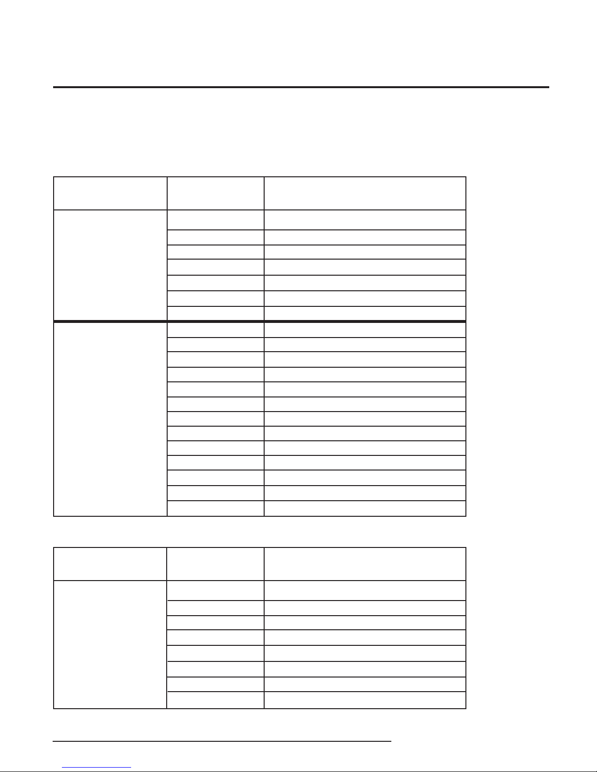
The following tables describe HART status information.
Table 6. MSB: HART First Byte
HCS
HART® Concentrator System
HART-to-MODBUS RTU Converter
MSB
Bit 7 = 1
Communications
Error
(The byte consists
of error FLAGS)
Bit 7 = 0
Command Response
(T (The byte is a numerical value repre-
senting a single error condition)
Bit/Code
0
1
2
3
4
5
6
0
1
2
3
4
5
6
7
8-15
16
28
32
64
Description
0 (undefined)
RX buffer overflow
0 (reserved)
Checksum error
Framing error
Overrun error
Parity error
No error
Undefined
Invalid selection
Passed parameter too large
Passed parameter too small
Too few bytes received
Device specific command error
In write protect mode
Multiple meanings
Access restricted
Multiple meanings
Device is busy
Command not implemented
Table 7. LSB: HART Second Byte
MSB
0 not used when
a communications
error exists
Bit
Description
0
1
2
3
4
5
6
7
Primary variable out of limits
Non primary variable out of limits
Analog output saturated
Analog output current fixed
More status available
Cold start
Configuration changed
Field device malfunction
The Interface Solution Experts 25
Page 26

HCS
HART® Concentrator System
HART-to-MODBUS RTU Converter
Installation
Installation consists of physically mounting the unit,
grounding the instrument, and completing the electrical connections.
Mounting the HCS
The HCS is designed to snap easily onto 32mm, Gtype (EN50035) or 35mm Top Hat (EN50022) DIN
rails.
Making the Electrical Connections
After mounting, you are ready to connect the HCS to
the loop. Each unit comes equipped with a transmitter
excitation terminal which allows it to supply power to
the monitored HART instrument, if necessary.
Figures 2 and 3 shows the connection diagram for
an HCS.
Recommended Ground Wiring
Practices
Moore Industries recommends the following ground
wiring practices:
• AnyMooreIndustriesproductinametalcase
or housing should be grounded.
• Theprotectiveearthconductormustbe
connected to a system safety earth ground
before making other connections.
Note:
Some of Moore Industries’ instruments can be
classified as receivers (IPT2, IPX2, etc.) and some
can be classified as transmitters (TRX, TRY, etc.)
while some are both a receiver and a transmitter
(SPA2, HIM, etc). Hence, your shield ground
connections should be appropriate for the type
of signal line being shielded. The shield should
be grounded at the receiver and not at the signal
source.
CE Conformity
Installation of any Moore Industries’ products that
carry CE certification (Commission Electrotechnique)
must adhere to the guidelines in Recommended
Ground Wiring Practices (above) in order to meet the
requirements set forth in applicable EMC (Electromagnetic Compatibility) directives 2004/108/EC, EN
61326. Consult the factory for the most current information on products that have been CE certified.
Power Sourcing Parameters for General
Locations, Intrinsically Safe and NonIncendive/Type N Applications
The input terminals must be connected to and/or
supplied from a certified energy limiting Class 2 or a
Separate Extra Low Voltage (S.E.L.V.) power supply
separated from all mains by double/reinforced
insulation.
• Allinputsignalsto,andoutputsignals
from, Moore Industries’ products should be
wired using a shielded, twisted pair wiring
technique. Shields should be connected to an
earth or safety ground.
• Forthebestshielding,theshieldshouldbe
run all the way from the signal source to the
receiving device. (see Note below)
• Themaximumlengthofunshieldedinputand
output signal wiring should be 2 inches.
26 The Interface Solution Experts
Page 27

HCS
HART® Concentrator System
HART-to-MODBUS RTU Converter
Operation
Once programmed, calibrated, installed, and supplied
with the correct power, the HCS begins to operate
immediately. Depending upon environmental
conditions, it can be expected to operate unattended
for extended periods of time.
There are 2 leds which indicate the unit and input
status:
INPUT LED: (Red/Green)
Green: Input is present and normal
Red: Input signal is not found
Red/Green blinking: HCS is in burst mode but
the slave is not
READY LED: (Red/Green)
Green: Instrument is ready for operation and
configuration
Red: Instrument has encountered an internal
problem
Maintenance
Moore Industries suggests a check for terminal
tightness and general unit condition every 6-8 months.
Always adhere to any site requirements for
programmed maintenance.
Customer Support
Moore Industries is recognized as the industry leader
in delivering top quality to its customers in products
and services. We perform a battery of stringent
quality assurance checks on every unit we ship. If
any Moore Industries product fails to perform up
to rated specifications, call us for help. Our highly
skilled staff of trained technicians and engineers pride
themselves on their ability to provide timely, accurate,
and practical answers to your process instrumentation
questions.
Factory phone numbers are listed on the back cover of
this manual.
If problems involve a particular HCS, there are several
pieces of information that can be gathered before
you call the factory that will help our staff get the
answers you need in the shortest time possible. For
fastest service, gather the complete model and serial
number(s) of the problem unit(s) and the job number
of the original sale.
The Interface Solution Experts 27
Page 28

HCS
HART® Concentrator System
HART-to-MODBUS RTU Converter
Appendix A: Configuring the Legacy HCS
The following information applies only to units with
firmware version older than 4.0.
Note:
All tables and figures within Appendix A relate only
to this Appendix A unless otherwise mentioned.
Configuring the HCS
One of the benefits of the HCS is that there are no
internal or external controls to adjust or settings to
change. All operating parameters are set using the PC
Configuration software.
Once these software settings are made, they are
downloaded to the instrument in the form of a
Configuration File and stored in the unit’s nonvolatile
memory. You can choose to save a backup copy of
the file on your PC hard drive or external media. The
HCS communicates with the PC through a proprietary
communications cable to the PC’s serial (COM) port or
optional proprietary USB cable to the PC’s USB port.
Installing the Configuration Software
Refer to Table 2 for the equipment needed.
1. Insert the
PC Configuration Software
of the PC. Access the CD and open the “HCS
PC Configuration Software” folder.
2. Double-click the installation program located in
the folder. Follow the prompts to correctly
install the program.
Once the Configuration Program is installed onto your
PC, the HCS can be connected into a system and
become operational.
Moore Industries Interface Solution
CD into the CD drive
Connecting the HCS to the PC
HCS can be connect to PC one of two ways:
• using the proprietary communications cable to
connect to PC’s serial (COM) port
• using the optional proprietary USB cable to
connect to PC’s USB port
Table 1. Necessary Equipment Table
Device Specifications
Power Supply
Personal Computer
Moore Industries
PC Configuration Software
Communication Cable
$ The Interface Solution Experts
See Table 1 for information on the necessary
equipment.
24Vdc, ±10%
80386-based (or faster) IBM PC, or 100% compatible (Pentium recommended);
CD Drive
4Mb free RAM; 16Mb recommended
20Mb free disk space on hard drive
Microsoft Windows® 2000, NT, XP, Vista, or 7 with Internet Explorer 4.0+ or
Microsoft Windows® NT with Service Pack 3 or greater
1 (one) serial port (COM 1, 2, 3 or 4) or USB port
Version 1.0 or higher, successfully installed onto the hard drive
Part# 803-053-26 or optional USB cable Part#208-836-00
Page 29
PC Configuration Software Summary
Figure 1. HCS PC Configuration Software Screen
1
8
2
3
4
5
HCS
HART® Concentrator System
HART-to-MODBUS RTU Converter
6
7
The HCS PC Configuration Software can be used to
program all of the instrument’s parameters. Once the
default configuration has been saved to disk, it is safe
to program other parameters.
The PC Software is composed of these sections:
1. Menu Bar/Tool Bar–Dropdown menus and corresponding icons allow you to perform various functions
throughout the PC Configuration Program.
Menu and Tool Bar Legend
scription.
2. Program Status–This portion of the program displays the activity (idle, monitoring, downloading, uploading) of the connected unit.
3. HCS Status–Notifies of any errors or conditions
which are outside of the tolerance range. Displays
HCS OK
if the unit is operating normally.
section for a complete de-
Refer to the
4. HCS Tag–A phrase used to identify an HCS (eight
alphanumeric characters, maximum).
5. HCS Device Info–Displays the individual characteristics of the attached HCS, such as the device ID,
hardware and software revisions and the last date that
the device was programmed.
6. Progress–This bar stays in motion any time the
HCS is monitoring, uploading or downloading, to notify
that a process is occurring.
7. Communications–Indicates current PC connection/communications status.
8. HART/MODBUS Tabs–These tabs change the right
side of the screen to allow you to set the appropriate
part of the HCS’s configuration. See corresponding
sections of this manual for additional information on
these tabs.
The Interface Solution Experts $
Page 30
HCS
HART® Concentrator System
HART-to-MODBUS RTU Converter
Menu and Tool Bar Legend
Allows such functions as New,
Open, Save and Print
Controls whether Tool and Status
Bars are viewed on the screen
Allows you to Upload and
Download configurations
Select the PC Port
(Com Port) that you will use
Allows you to Monitor and
Stop monitoring processes
Displays the version of the HCS
Configuration Program
Configuration Screens
HART
Figure 2. HART Tab
Slave Devices
Once you have selected the number of HART slaves
to be used in the loop, use this section to assign a
specific address for each device. Ensure that the address matches the address of the slave you connected in the loop. Each must be a unique address
between zero and 63. However, Address 0 is an analog address and is not used in HART multi-drop loops.
Current readings at this address can vary from 3.6mA
to 23.6mA.
Master Mode
The HART protocol allows for two communications
masters on the loop: a Primary Master and a Secondary Master. Setting the HCS to function as the Primary
HART Master in the application means that any other
HART device in the loop must be configured either as
a HART Secondary Master (1 per loop), or as a HART
Slave (up to 16 per loop). Conversely, setting the HCS
to function as the Secondary HART Master allows
other HART devices to function either as a Primary
Master, or as Slaves. Configuring more than one device on a single loop as a Primary or Secondary HART
Master will cause a communications failure.
Number of HART Slaves
Using the up and down arrows, select the number of
HART slaves (16 maximum) that you will introduce into
your loop. The number of slaves you have chosen will
appear as enabled in the
Slave Devices
parameter.
Note:
A HART hand-held communicator is typically a
Secondary Master.
Number of Retries
The
Number of Retries
and will determine how many times the HCS will attempt to poll the HART transmitter (without success),
before it indicates a HART communication failure.
can be set between 1 and 3,
Burst Mode
Allows selection of Normal or Burst modes.
Burst mode may be enabled if there is only one slave
in the loop.
The HCS can operate in one of two modes:
Burst
. In each of these modes the HCS attempts to
find a HART transmitter.
Normal
or
$ The Interface Solution Experts
Page 31
In
Normal
transmitter, then polls the HART instrument twice per
second, requesting the current process status and the
HART instrument's diagnostic status. The HART instrument responds with the requested data.
In
Burst
grammed to continuously transmit its process variable
and health status. The HCS samples the continuous
HART data three times per second.
The instrument will operate in Normal Mode by default.
Selecting the
Mode.
mode, the HCS polls the HART loop for a
mode, the monitored HART instrument is pro-
Burst Mode
button will enable Burst
MODBUS
Figure 3. MODBUS Tab
HCS
HART® Concentrator System
HART-to-MODBUS RTU Converter
Baud Rate
The
Baud Rate
transmission. It should be set to match the baud rate
of the attached controller. The interface supports the
following baud rates: 300, 600, 1200, 2400, 4800, 9600
and 19200.
Parity
The HART monitor supports even, odd and no
The data format is one start bit, 8 data bits and one
stop bit.
30,000 / 40,000 Register Formatting
This section includes the following areas:
Register Grouping
This allows you to select the manner in which to group
the MODBUS registers.
is the speed of MODBUS data
Parity.
The
MODBUS tab
communications parameters.
allows you to set the MODBUS
Communications Settings
The Communications Settings include three areas:
MODBUS Address (Decimal)
The
MODBUS Address
monitor uses to identify itself on the MODBUS
network. The MODBUS address is configurable from 1
to 247. By default, it will assume a MODBUS address
of 1.
is the number that the HCS
Selecting
in order of
grouped together, followed by secondary variables
(SV), third (TV) and then fourth (FV).
Using
registers in order
device’s variables in contiguous registers. For example, your first HART device’s primary, secondary,
third and fourth variables (PV1, SV1, TV1 and FV1)
are grouped together. Next in the order are your second HART device’s primary, secondary, third and
fourth variables (PV2, SV2, TV2 and FV2) and so on.
By Variable Type,
variables
By HART Slave Device
, i.e. all primary variables (PV) are
numerically
the registers are grouped
grouping places your
. It groups a HART slave
Floating Point Word Order
By default, the HART Concentrator will use the
dard LSW
order format. This stores the most significant bits in
the second register and the least significant bits in the
first register. Selecting
cant word)
nificant bits in the first register and the least significant
bits in the second register.
(least significant word) floating point word
Swapped MSW (most signifi-
will reverse the order, storing the most sig-
Stan-
The Interface Solution Experts $
Page 32

HCS
HART® Concentrator System
HART-to-MODBUS RTU Converter
Failed Slave’s Register Value
You may select what would occur to a slave device’s
register value in the event that communication is lost
with the HCS.
If selecting
the last measured value before the failure occurred is
held.
Entering a user-set value in the
calls that value when a slave device failure is detected.
Selecting
IEEE-754 standard) causes the floating point NaN
value to be stored in the registers used for holding
floating point values.
Hold Last Value
NaN
(Not a Number–as put forth by the
and a failure is detected,
Preset to
text box re-
$ The Interface Solution Experts
Page 33
MODBUS Register Definitions
Tables 2-5 define the MODBUS input and holding
register assignment. These tables are zero based,
your MODBUS host may require you to enter the
MODBUS register. Often registers have an offset of
“1” from the MODBUS address. For example, a
MODBUS address listed below of 256 may have to be
entered as 257 in your host. Please refer to your
MODBUS host documentation for verification.
KEY:
FV = Fourth Variable
LSB = Least Significant Bit
MSB = Most Significant Bit
PV = Primary Variable
*Moore Industries provides up to 169 HART Engineering Units listed in HART Communication
Foundation document number: HCF-SPEC-183, Revision 14.0, Release Date 29 January 2004
SV = Secondary Variable
TV = Third Variable
*UOM = Unit of Measurement
HCS
HART® Concentrator System
HART-to-MODBUS RTU Converter
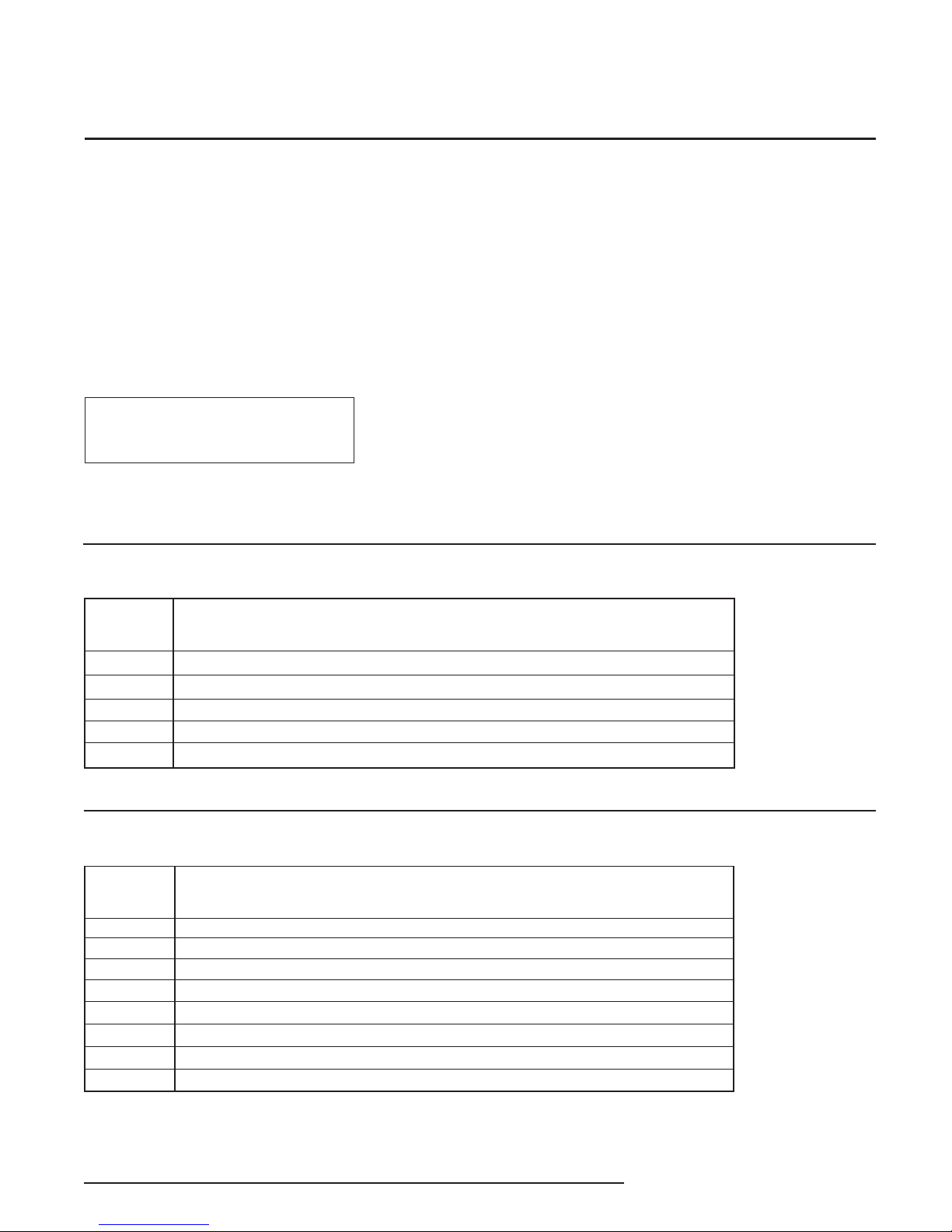
Table 2. Register ranges and descriptions when MODBUS registers are grouped by the “By Variable Type” parameter and only the PV and
SV are being stored (when nine or more slaves are in the loop)
Register
Description
Range
32-47
48-63
64
256-287
288-319
Table 3. Register ranges and descriptions when MODBUS registers are grouped by the “By Variable Type” parameter and all dynamic
variables are being stored (when eight or fewer slaves are in the loop)
Register
HART Device 1-16 HART Status
HART Device 1-16 PV + SV UOM (PV UOM = MSB, SV UOM = LSB)
HCS Status
HART Device 1-16 PV floating point value stored in 2x16-bit registers per float
HART Device 1-16 SV floating point value stored in 2x16-bit registers per float
Description
Range
32-39
40-47
48-55
64
256-271
272-287
288-303
304-319
HART Device 1-8 HART Status
HART Device 1-8 PV + SV UOM (PV UOM = MSB, SV UOM = LSB)
HART Device 1-8 TV + FV UOM (TV UOM = MSB, FV UOM = LSB)
HCS Status
HART Device 1-8 PV floating point value stored in 2x16-bit registers per float
HART Device 1-8 SV floating point value stored in 2x16-bit registers per float
HART Device 1-8 TV floating point value stored in 2x16-bit registers per float
HART Device 1-8 FV floating point value stored in 2x16-bit registers per float
The Interface Solution Experts $
Page 34

HC
HART® Concentrator System
HART-to-MODBUS RTU Converter
Table 4. Register ranges and descriptions when MODBUS registers are grouped by the “By HART Slave Device” parameter (when nine or
more slaves are in the loop)
Register
Range
2
3
6
7
10
11
14
15
18
19
22
23
26
27
30
31
34
35
38
39
42
43
46
47
50
51
54
55
58
59
62
63
64
256-257
258-259
260-261
262-263
264-265
Description
HART Device 1 HART Status
HART Device 1 UOM (PV UOM = MSB, SV UOM = LSB)
HART Device 2 HART Status
HART Device 2 UOM (PV UOM = MSB, SV UOM = LSB)
HART Device 3 HART Status
HART Device 3 UOM (PV UOM = MSB, SV UOM = LSB)
HART Device 4 HART Status
HART Device 4 UOM (PV UOM = MSB, SV UOM = LSB)
HART Device 5 HART Status
HART Device 5 UOM (PV UOM = MSB, SV UOM = LSB)
HART Device 6 HART Status
HART Device 6 UOM (PV UOM = MSB, SV UOM = LSB)
HART Device 7 HART Status
HART Device 7 UOM (PV UOM = MSB, SV UOM = LSB)
HART Device 8 HART Status
HART Device 8 UOM (PV UOM = MSB, SV UOM = LSB)
HART Device 9 HART Status
HART Device 9 UOM (PV UOM = MSB, SV UOM = LSB)
HART Device 10 HART Status
HART Device 10 UOM (PV UOM = MSB, SV UOM = LSB)
HART Device 11 HART Status
HART Device 11 UOM (PV UOM = MSB, SV UOM = LSB)
HART Device 12 HART Status
HART Device 12 UOM (PV UOM = MSB, SV UOM = LSB)
HART Device 13 HART Status
HART Device 13 UOM (PV UOM = MSB, SV UOM = LSB)
HART Device 14 HART Status
HART Device 14 UOM (PV UOM = MSB, SV UOM = LSB)
HART Device 15 HART Status
HART Device 15 UOM (PV UOM = MSB, SV UOM = LSB)
HART Device 16 HART Status
HART Device 16 UOM (PV UOM = MSB, SV UOM = LSB)
HCS Status
HART Device 1 PV floating point value stored in 2x16-bit register per float
HART Device 1 SV floating point value stored in 2x16-bit register per float
HART Device 2 PV floating point value stored in 2x16-bit register per float
HART Device 2 SV floating point value stored in 2x16-bit register per float
HART Device 3 PV floating point value stored in 2x16-bit register per float
Continued on next page
$ The Interface Solution Experts
Page 35

Table 4. Continued
HCS
HART® Concentrator System
HART-to-MODBUS RTU Converter
266-267
268-269
270-271
272-273
274-275
276-277
278-279
280-281
282-283
284-285
286-287
288-289
290-291
292-293
294-295
296-297
298-299
300-301
302-303
304-305
306-307
308-309
310-311
312-313
314-315
316-317
318-319
HART Device 3 SV floating point value stored in 2x16-bit register per float
HART Device 4 PV floating point value stored in 2x16-bit register per float
HART Device 4 SV floating point value stored in 2x16-bit register per float
HART Device 5 PV floating point value stored in 2x16-bit register per float
HART Device 5 SV floating point value stored in 2x16-bit register per float
HART Device 6 PV floating point value stored in 2x16-bit register per float
HART Device 6 SV floating point value stored in 2x16-bit register per float
HART Device 7 PV floating point value stored in 2x16-bit register per float
HART Device 7 SV floating point value stored in 2x16-bit register per float
HART Device 8 PV floating point value stored in 2x16-bit register per float
HART Device 8 SV floating point value stored in 2x16-bit register per float
HART Device 9 PV floating point value stored in 2x16-bit register per float
HART Device 9 SV floating point value stored in 2x16-bit register per float
HART Device 10 PV floating point value stored in 2x16-bit register per float
HART Device 10 SV floating point value stored in 2x16-bit register per float
HART Device 11 PV floating point value stored in 2x16-bit register per float
HART Device 11 SV floating point value stored in 2x16-bit register per float
HART Device 12 PV floating point value stored in 2x16-bit register per float
HART Device 12 SV floating point value stored in 2x16-bit register per float
HART Device 13 PV floating point value stored in 2x16-bit register per float
HART Device 13 SV floating point value stored in 2x16-bit register per float
HART Device 14 PV floating point value stored in 2x16-bit register per float
HART Device 14 SV floating point value stored in 2x16-bit register per float
HART Device 15 PV floating point value stored in 2x16-bit register per float
HART Device 15 SV floating point value stored in 2x16-bit register per float
HART Device 16 PV floating point value stored in 2x16-bit register per float
HART Device 16 SV floating point value stored in 2x16-bit register per float
The Interface Solution Experts $
Page 36

HCS
HART® Concentrator System
HART-to-MODBUS RTU Converter
Table 5. Register ranges and descriptions when MODBUS registers are grouped by the “By HART Slave Device” parameter and PV, SV,
TV and FV are being stored (when eight or fewer slaves are in the loop)
Register
Range
4
5
6
7
12
13
14
15
20
21
22
23
28
29
30
31
36
37
38
39
44
45
46
47
52
53
54
55
60
61
62
63
64
256-257
258-259
260-261
262-263
264-265
Description
HART Device 1 HART Status
HART Device 1 PV & SV UOM (PV UOM = MSB, SV UOM = LSB)
HART Device 1 TV & FV UOM (TV UOM = MSB, FV UOM = LSB)
Not assigned
HART Device 2 HART Status
HART Device 2 PV & SV UOM (PV UOM = MSB, SV UOM = LSB)
HART Device 2 TV & FV UOM (TV UOM = MSB, FV UOM = LSB)
Not assigned
HART Device 3 HART Status
HART Device 3 PV & SV UOM (PV UOM = MSB, SV UOM = LSB)
HART Device 3 TV & FV UOM (TV UOM = MSB, FV UOM = LSB)
Not assigned
HART Device 4 HART Status
HART Device 4 PV & SV UOM (PV UOM = MSB, SV UOM = LSB)
HART Device 4 TV & FV UOM (TV UOM = MSB, FV UOM = LSB)
Not assigned
HART Device 5 HART Status
HART Device 5 PV & SV UOM (PV UOM = MSB, SV UOM = LSB)
HART Device 5 TV & FV UOM (TV UOM = MSB, FV UOM = LSB)
Not assigned
HART Device 6 HART Status
HART Device 6 PV & SV UOM (PV UOM = MSB, SV UOM = LSB)
HART Device 6 TV & FV UOM (TV UOM = MSB, FV UOM = LSB)
Not assigned
HART Device 7 HART Status
HART Device 7 PV & SV UOM (PV UOM = MSB, SV UOM = LSB)
HART Device 7 TV & FV UOM (TV UOM = MSB, FV UOM = LSB)
Not assigned
HART Device 8 HART Status
HART Device 8 PV & SV UOM (PV UOM = MSB, SV UOM = LSB)
HART Device 8 TV & FV UOM (TV UOM = MSB, FV UOM = LSB)
Not assigned
HCS Status
HART Device 1 PV floating point value stored in 2x16-bit register per float
HART Device 1 SV floating point value stored in 2x16-bit register per float
HART Device 1 TV floating point value stored in 2x16-bit register per float
HART Device 1 FV floating point value stored in 2x16-bit register per float
HART Device 2 PV floating point value stored in 2x16-bit register per float
$ The Interface Solution Experts
Continued on next page
Page 37

Table 5. Continued
HCS
HART® Concentrator System
HART-to-MODBUS RTU Converter
266-267
268-269
270-271
272-273
274-275
276-277
278-279
280-281
282-283
284-285
286-287
288-289
290-291
292-293
294-295
296-297
298-299
300-301
302-303
304-305
306-307
308-309
310-311
312-313
314-315
316-317
318-319
HART Device 2 SV floating point value stored in 2x16-bit register per float
HART Device 2 TV floating point value stored in 2x16-bit register per float
HART Device 2 FV floating point value stored in 2x16-bit register per float
HART Device 3 PV floating point value stored in 2x16-bit register per float
HART Device 3 SV floating point value stored in 2x16-bit register per float
HART Device 3 TV floating point value stored in 2x16-bit register per float
HART Device 3 FV floating point value stored in 2x16-bit register per float
HART Device 4 PV floating point value stored in 2x16-bit register per float
HART Device 4 SV floating point value stored in 2x16-bit register per float
HART Device 4 TV floating point value stored in 2x16-bit register per float
HART Device 4 FV floating point value stored in 2x16-bit register per float
HART Device 5 PV floating point value stored in 2x16-bit register per float
HART Device 5 SV floating point value stored in 2x16-bit register per float
HART Device 5 TV floating point value stored in 2x16-bit register per float
HART Device 5 FV floating point value stored in 2x16-bit register per float
HART Device 6 PV floating point value stored in 2x16-bit register per float
HART Device 6 SV floating point value stored in 2x16-bit register per float
HART Device 6 TV floating point value stored in 2x16-bit register per float
HART Device 6 FV floating point value stored in 2x16-bit register per float
HART Device 7 PV floating point value stored in 2x16-bit register per float
HART Device 7 SV floating point value stored in 2x16-bit register per float
HART Device 7 TV floating point value stored in 2x16-bit register per float
HART Device 7 FV floating point value stored in 2x16-bit register per float
HART Device 8 PV floating point value stored in 2x16-bit register per float
HART Device 8 SV floating point value stored in 2x16-bit register per float
HART Device 8 TV floating point value stored in 2x16-bit register per float
HART Device 8 FV floating point value stored in 2x16-bit register per float
The Interface Solution Experts A-10
Page 38

HC
HART® Concentrator System
HART-to-MODBUS RTU Converter
Table 6. HCS Status Word Bits
Status
Word Bit
0
1
2
3
4
5
6
7
8
10
11
12
13
14
15
Table 7. Slave Device Status
Type
Error
Error
Error
Error
Status
Error
Error
Error
Status
Error
Status
Not Used
Not Used
Not Used
Error
Description
Configuration data error
No HART communications
EEPROM blank
EEPROM failure
Slave device malfunction
Burst mode failure
Software watchdog failure
COP watchdog failure
Slave device analog output fixed
Software fail
Device offline
N/A
N/A
N/A
Configuration data area checksum error
Status Bit
0
1
2
3
4
5
6
7
Description
Primary variable out of limits
Non-Primary variable out of limits
Analog output #1 saturated
Analog output #1 fixed
More status available
Cold start
Configuration changed
Field device malfunction
A-11 The Interface Solution Experts
Page 39
HCS
HART® Concentrator System
HART-to-MODBUS RTU Converter
Appendix B: HCS HART
compatibility
To configure this new version of HCS you must also
use the newest version of the HCS PC Configuration
software (v3.6 or newer).
The Moore Industries HCS was updated in February
2014 to be multi-version compatible with HART 5, 6
and 7 devices by the release of new HCS firmware
v5.2. It communicates with HART 5, 6, and 7
compliant devices in both multi-drop and single point
This version of the HCS PC Configuration software
is also backward compatible with all earlier versions
Note:
of the HCS.
networks. The HCS fully supports networks where
HART slaves and other hosts have different HART
versions. While this version of the HCS is compatible
with HART 5, 6 and 7 it does not support ALL of the
new features available in HART 6 and 7.
The HCS uses the following HART commands 0, 3, 13
and 48 to collect its data.
Command 0 Read transmitter unique identifier
Command 3 Read all dynamic variables and current
Command 13 Read tag, descriptor, date
Command 48 Read additional transmitter status
Table B-1. The following table outlines how each generation of HCS works with HART devices:
3RD GENERATION
(CURRENT VERSION)
HCS Firmware v5.2 and Later HCS Firmware v4.x (2nd generation)
PC Software HCS Software v3.6 and later HCS Software v3.0 and later (2nd generation)
Burst Mode
Extended Mfg’s
ID and Device
Type
Additional Status
Bytes
Error Bits
If Burst mode is selected on the HCS it will NOT
send a command to the attached HART slave to
set it into Burst mode.
If there is a power cycle on the HART loop the
HCS will NOT send a command to the attached
HART slave to set it into Burst mode.
Note: If you know your HART slave boots up in the
Poll/Response mode you should configure the
HCS for Normal Mode communication to avoid
having to reconfigure the slave after power upsets.
HART 5 supports 1 byte per HART slave; HART 6
and 7 support 2 bytes per slave. This version of
HCS will read HART 5, 6, and 7 slave
Manufacturer ID and Device Type.
HART 5 supports 6 bytes per HART slave; HART
6 and 7 support 25 bytes per slave. This version
of the HCS reads the 6 Additional Status Bytes in
HART 5 slaves and reads all 25 Additional Status
Bytes in HART 6 and 7 slaves.
When communication from the HART slave to the
HCS fails, only the Device Malfunction bit is set.
1st & 2ND GENERATION
HCS Firmware v3.x and earlier (1
If Burst mode is selected on the HCS it will send
a command to the attached HART slave to set it
into Burst mode.
If there is a power cycle on the HART loop the
HCS would again send a command to the
attached HART slave to set it into Burst mode.
HART 5 supports 1 byte per HART slave; HART
6 and 7 support 2 bytes per slave. This version
of HCS will ONLY read HART 5 slave
Manufacturer ID and Device Type but will NOT
read the ID and Device Type from HART 6 and 7
slaves. This limitation with HART 6 and 7 slaves
does not affect communications.
HART 5 supports 6 bytes per HART slave; HART
6 and 7 support 25 bytes per slave. This version
of the HCS only reads the first 6 Additional
Status Bytes in HART 5, 6 and 7 slaves. This
limitation with HART 6 and 7 slaves does not
affect communications.
Not supported in 1
When communication from the HART slave to
the HCS fails, ALL error bits are set.
st
generation HCS (legacy)
st
generation)
The Interface Solution Experts B-1
Page 40

HCS
HART® Concentrator System
HART-to-MODBUS RTU Converter
HART 6 and 7 Features not currently
supported:
Long Tag:
32 character tag. Only the regular 8 character tag is
supported. The 8 character tag and the 32 character
tag are completely different data objects and will not
interfere with each other. The 32 character tag can be
programmed in the slave without having any effect on
the HCS operation, but it will not be read by the HCS.
Multi-Variable Statuses:
Provides “output quality” information for all variables.
This information is not yet read by the HCS.
Enhanced Multi-Variable Communication (8):
Increases device output capability from 4 to 8
variables using command 9. Only 4 variables
(Primary, Secondary, Third and Fourth) are currently
read by the HCS using command 3.
B-2 The Interface Solution Experts
Page 41

EC Declaration of Conformity
Moore Industries-International, Inc. Date Issued: 04 Dec. 2013
16650 Schoenborn Street No. 100-100-247 Rev. B
North Hills, CA 91343-6196 U.S.A. Page 1 of 1
Equipment Description:
HART Concentrator System (HART-to-MODBUS RTU Converter)
Model HCS / * / * / * / * / *
* Indicates any input, output, power, options and housing as stated in the product data sheet.
Directive:
2004/108/EC (EMC)
Specifications Conformed To:
EN 61326-1:2006
Electrical equipment for measurement, control and laboratory use - EMC requirements
On Behalf of Moore Industries-International, Inc., I declare that, on the date the equipment accompanied by this
declaration is placed on the market, the equipment conforms with all technical and regulatory requirements of
the above listed directives.
Signature: Deanna Esterwold, Quality Manager
Page 42

RETURN PROCEDURES
United States • inf[email protected]
Tel: (818) 894-7111 • FAX: (818) 891-2816
Australia • [email protected]
Tel: (02) 8536-7200 • FAX: (02) 9525-7296
Belgium • inf[email protected]
Tel: 03/448.10.18 • FAX: 03/440.17.97
The Netherlands • [email protected]
Tel: (0)344-617971 • FAX: (0)344-615920
China • [email protected]
Tel: 86-21-62491499 • FAX: 86-21-62490635
United Kingdom • [email protected]
Tel: 01293 514488 • FAX: 01293 536852
To return equipment to Moore Industries for repair, follow these four steps:
1. Call Moore Industries and request a Returned Material Authorization (RMA) number.
Warranty Repair –
If you are unsure if your unit is still under warranty, we can use the unit’s serial number
to verify the warranty status for you over the phone. Be sure to include the RMA
number on all documentation.
Non-Warranty Repair –
If your unit is out of warranty, be prepared to give us a Purchase Order number when
you call. In most cases, we will be able to quote you the repair costs at that time.
The repair price you are quoted will be a “Not To Exceed” price, which means that the
actual repair costs may be less than the quote. Be sure to include the RMA number
on all documentation.
2. Provide us with the following documentation:
a) A note listing the symptoms that indicate the unit needs repair
b) Complete shipping information for return of the equipment after repair
c) The name and phone number of the person to contact if questions arise at the factory
3. Use sufficient packing material and carefully pack the equipment in a sturdy shipping
container.
4. Ship the equipment to the Moore Industries location nearest you.
The returned equipment will be inspected and tested at the factory. A Moore Industries
representative will contact the person designated on your documentation if more information
is needed. The repaired equipment, or its replacement, will be returned to you in accordance
with the shipping instructions furnished in your documentation.
WARRANTY DISCLAIMER
THE COMPANY MAKES NO EXPRESS, IMPLIED OR STATUTORY WARRANTIES (INCLUDING ANY WARRANTY OF MERCHANTABILITY OR
OF FITNESS FOR A PARTICULAR PURPOSE) WITH RESPECT TO ANY
GOODS OR SERVICES SOLD BY THE COMPANY. THE COMPANY DISCLAIMS ALL WARRANTIES ARISING FROM ANY COURSE OF DEALING
OR TRADE USAGE, AND ANY BUYER OF GOODS OR SERVICES FROM
THE COMPANY ACKNOWLEDGES THAT THERE ARE NO WARRANTIES
IMPLIED BY CUSTOM OR USAGE IN THE TRADE OF THE BUYER AND
OF THE COMPANY, AND THAT ANY PRIOR DEALINGS OF THE BUYER
WITH THE COMPANY DO NOT IMPLY THAT THE COMPANY WARRANTS
THE GOODS OR SERVICES IN ANY WAY.
ANY BUYER OF GOODS OR SERVICES FROM THE COMPANY
AGREES WITH THE COMPANY THAT THE SOLE AND EXCLUSIVE REMEDIES FOR BREACH OF ANY WARRANTY CONCERNING THE GOODS OR
SERVICES SHALL BE FOR THE COMPANY, AT ITS OPTION, TO REPAIR
OR REPLACE THE GOODS OR SERVICES OR REFUND THE PURCHASE
PRICE. THE COMPANY SHALL IN NO EVENT BE LIABLE FOR ANY CONSEQUENTIAL OR INCIDENTAL DAMAGES EVEN IF THE COMPANY FAILS
IN ANY ATTEMPT TO REMEDY DEFECTS IN THE GOODS OR SERVICES
, BUT IN SUCH CASE THE BUYER SHALL BE ENTITLED TO NO MORE
THAN A REFUND OF ALL MONIES PAID TO THE COMPANY BY THE BUYER
FOR PURCHASE OF THE GOODS OR SERVICES.
ANY CAUSE OF ACTION FOR BREACH OF ANY WARRANTY BY
THE COMPANY SHALL BE BARRED UNLESS THE COMPANY RECEIVES FROM THE BUYER A WRITTEN NOTICE OF THE ALLEGED
DEFECT OR BREACH WITHIN TEN DAYS FROM THE EARLIEST DATE
ON WHICH THE BUYER COULD REASONABLY HAVE DISCOVERED
THE ALLEGED DEFECT OR BREACH, AND NO ACTION FOR THE
BREACH OF ANY WARRANTY SHALL BE COMMENCED BY THE
BUYER ANY LATER THAN TWELVE MONTHS FROM THE EARLIEST
DATE ON WHICH THE BUYER COULD REASONABLY HAVE DISCOVERED THE ALLEGED DEFECT OR BREACH.
RETURN POLICY
For a period of thirty-six (36) months from the date of shipment, and under
normal conditions of use and service, Moore Industries (“The Company”)
will at its option replace, repair or refund the purchase price for any of its
manufactured products found, upon return to the Company (transportation
charges prepaid and otherwise in accordance with the return procedures
established by The Company), to be defective in material or workmanship.
This policy extends to the original Buyer only and not to Buyer’s customers
or the users of Buyer’s products, unless Buyer is an engineering contractor
in which case the policy shall extend to Buyer’s immediate customer only.
This policy shall not apply if the product has been subject to alteration,
misuse, accident, neglect or improper application, installation, or operation.
THE COMPANY SHALL IN NO EVENT BE LIABLE FOR ANY INCIDENTAL
OR CONSEQUENTIAL DAMAGES.
Specifications and Information subject to change without notice.© 2014 Moore Industries-International, Inc.
 Loading...