

Page 1
November 2013
165-730-00E1
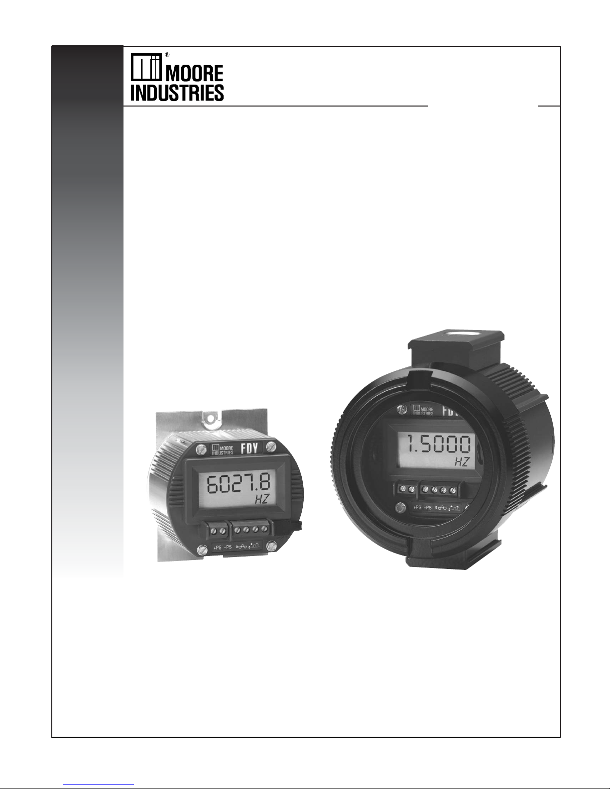
PC-Programmable Frequency
Transmitter and Display
FDY
PC-Programmable Frequency
Transmitter and Display
FDY
Page 2

Table of Contents
The FDY .............................................................................................................. 3
About this Manual ................................................................................................................3
Specifi cations .................................................................................................... 4
PC Confi guration Software ............................................................................... 6
Programming the FDY ....................................................................................... 8
Connecting the FDY to the PC .............................................................................................8
Programming the Basic Parameters ....................................................................................9
Programming the Input Parameters .....................................................................................9
Programming the Range Parameters .................................................................................10
Programming the Output Parameters ................................................................................11
Programming the Trimming Parameters .............................................................................12
Sensor Trimming ...................................................................................................................................... 12
Output Trimming ...................................................................................................................................... 13
Loop Test ................................................................................................................................................. 13
Programming the Custom Curve Parameters ....................................................................14
Editing the Custom Curve Table .........................................................................................15
Downloading the Confi guration File ...................................................................................15
Installing the FDY ............................................................................................ 16
Customer Service ............................................................................................ 17
Appendix-A Intrinsically-Safe Applications .................................................. 18
2 The Interface Solution Experts
Page 3
FDY
PC-Programmable Frequency
Transmitter and Display
The FDY
This is the user’s manual for the Moore Industries’ FDY
PC-Programmable Frequency Transmitter and
Display. Incredibly versatile, the FDY programs in less
than a minute to accept varying frequency signals from
AC or DC fl ow measurement devices such as
About this Manual
Wherever you see a “ Note”, “ Caution” or “ WARNING ”
pay particular attention.
• A “Note” provides information to help you in avoiding
minor inconveniences during calibration, installation
or operation of the FDY.
turbine meters and magnetic pick-up coils.
• A “Caution” provides information on steps to take
The FDY monitors the signal, outputting the selected
variable (frequency, period, high pulse width, low pulse
width or contact closure) both to its display and to a
4-20mA signal that is linear and input-scaleable. The
FDY features a large integral display that shows
in avoiding procedures and practices that could risk
damage to the FDY or other equipment.
• A “WARNING ” provides information on steps to take
in avoiding procedures and practices that could pose
safety risks to personnel.
real-time process status.
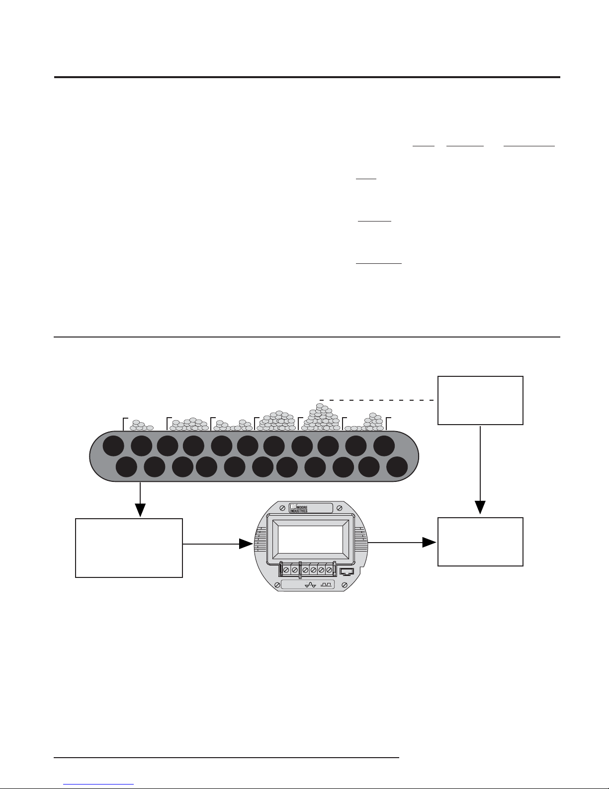
Figure 1. The FDY Accepts a Frequency Signal and Outputs a Scaleable 4-20mA Signal
eight
Measurement
Device
elt peed
Magnetic Pick- p,
Tachometer enerator,
all ffect ensor, or
other Frequency sensor
Input
FDY
6027.8
HZ
P
P
0
0
The Interface Solution Experts 3
CM
4-20mA
MD or
Weighing
ystem
Page 4

FDY
PC-Programmable Frequency
Transmitter and Display
Specifi cations
Performance
Input Accuracy:
See Tables 2-7
Output Accuracy: ±0.015%
of span
Overall Accuracy: The
overall accuracy of the unit
is the combined input and
output accuracies. It includes
the combined effects
of linearity, hysteresis,
repeatability and adjustment
resolution. Does not include
ambient temperature effect.
Input Hysteresis:
See Tables 5-7
Input Threshold:
See Tables 5-7
Stability: See Table 1
Minimum Frequency: Twice
the lower range
Digital Input Filter:
3dB point is at 10kHz
Step Response Time:
300msec maximum,
200msec typical from the
time an input is applied to
the output reaching 90% of
its fi nal value + actual input
Rise Time: 100msec
maximum for the output to
change from 10% to 90%
of its scale of an input step
change of 0% to 100% +
actual input
Isolation: 500Vrms
between input, output,
and case continuous, and
will withstand a 500 Vac
dielectric strength test
for one minute with no
breakdown
Ripple: 10mV peak-to-peak
measured across a 250 ohm
resistor
Overcurrent Limiting:
25mA maximum
Maximum Voltages: 48Vdc
output, maximum; DC
input, 48Vdc, maximum; AC
input, 30Vac maximum for
0.02-30AC model, 250Vac
maximum for 10-250AC
model
Performance
(Continued)
Input Impedance:
>30kohms for DC and
contact closure inputs;
2kohms for input >6V,
4kohms typical@50Hz and
56kohms typical@1kHz for
input <6V for
0.02-30AC model;
>125kohms for 10-250AC
model
Load Capability:
(508 ohms@24V)
Supply Voltage - 12V
0.0236A
Output Current Limiting:
3.8mA and 21.4mA for
input under range and over
range; 3.6mA and 23.6mA
for input failure
Load Effect (current
outputs): Negligible within
specifi ed power limits
Power Supply Effect:
±0.002% of span per 1V
change
Startup Time: Performance
within specifi cation less
than 1sec after power is
applied for frequency higher
than 100Hz and average of
8 samples
Damping: Adjustable from
0 to 30 seconds with PC
software
Linearization: Confi gurable
up to 128 points with PC
software
Moving Average:
Confi gurable up to 16
segments with PC software
Low Pass Filter:
On/Off is software
confi gurable
=
Ohms
Display
Ambient
Conditions
Weight
Type: LCD; Top Row,
10.16mm (0.4 in) high
black digits on a refl ective
background; Bottom Row,
5.72mm (0.225 in) high
black digits on a refl ective
background
Display Update Rate:
100msec
Format: Top row is fi ve
alphanumeric characters,
plus sign and decimal
point; bottom is fi ve
alphanumeric characters
Range: -99999 to 99999
Minimum Display Span:
1.00
Operating & Storage
Range:
-40 to +85°C
(-40°F to +185°F);
I.S. Operating Range:
-40° to +65°C
(-40°F to +149°F);
Relative Humidity:
0-95%, non-condensing
Ambient Temperature
Effect: Input to output,
±0.007% of span/°C
maximum; Digital
Accuracy, ±0.003% of
span/°C maximum
RFI/EMI Immunity:
30V/m when tested
according to SAMA 33.1
abc with 0.5% of span or
less error. 20V/m@
80-1000MHz, 1kHz AM,
when tested according to
IEC1000-4-3-1995
Noise Rejection:
Common mode, 120dB
typical@100mVp-p input
FDY HP: 227g (5.3 oz)
FDY in BH housing with
glass cover: 1.45kg
(3 lbs, 12.4 oz)
FDY in D-BOX housing:
811g (1 lb, 6.3 oz)
Specifi cations and information subject to change without notice.
4 The Interface Solution Experts
Page 5
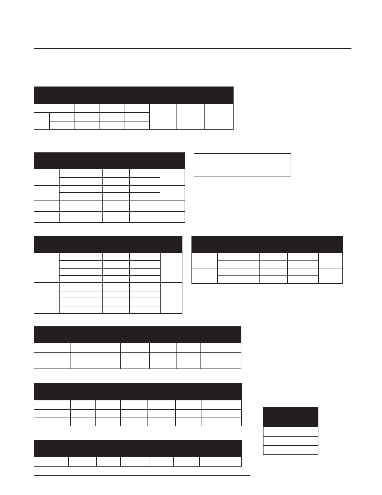
Table 1. Stability for All Models*
Input-to-Display (% of Reading)
1 year
Frequency/Period
1 Sec
Pulse
Width
0.1 Sec
*Combine Input-to-Display and Display-to-Output values to determine overall stability.
**Consult factory for improved long-term drift specifi cations.
0.001
0.001
0.0015
3 years
0.0017
0.0017
0.0026
5 years
Display-to-Output (% of Output Span**)
1 year
0.0022
0.0022
0.0034
0.08
Table 2. DC Input Range and Accuracy for All FDY Models
Input Type
Frequency
Period
Pulse
Width
Contact
Closure
Input Range
Frequency
0.02Hz to 5kHz
0.02Hz to 25kHz
200µsec to 50sec
40µsec to 50sec
0.5msec to 50sec
<20Hz
Amplitude
100mV-30V
200mV
-30V
100mV-30V
200mV-30V
1-30V
Accuracy
(% of reading)
0.01±1LSD
0.05±1LSD
0.01±1LSD
0.05±1LSD
0.05±1LSD
±2µsec
0.01±1LSD
Min.
Span
See
Table 8
500µsec
500µsec
0.1Hz
3 years
0.139
5 years
0.179
NOTE:
AC indicates zero-crossing signal.
DC indicates non-zero crossing signal.
FDY
PC-Programmable Frequency
Transmitter and Display
Table 3. AC Input Range and Accuracy for PRG Input Type
Input Type
Frequency
Period
Input Range
Frequency
0.5Hz to 25kHz
1Hz to 5kHz
1Hz to 25kHz
10Hz to 5kHz
40µsec to 2sec
200µsec to 1sec
40µsec to 50sec
200µsec to 100msec
Amplitude
1-30V
200mV
200mV-30V
20mV-30V
1-30V
200mV-30V
200mV-30V
20mV
(% of Reading)
-30V
-30V
Accuracy
0.05±1LSD
0.01±1LSD
0.05±1LSD
0.01±1LSD
0.05±1LSD
0.01±1LSD
0.05±1LSD
0.01±1LSD
Table 5. Frequency Input Parameters
Input Range
100mV-30V (DC)
20mV-30V (AC)
10V-250V(AC)
Threshold
Resolution
1mV
Range
0.01-2.5V
Hysteresis
Resolution
1mV
1mV
1mV
Range
0.01-1.5V
0.002-0.15V
0.002-0.15V
Table 6. Period Input Parameters
Input Range
100mV-30V (DC)
20mV-30V (AC)
10V-250V (AC)
Threshold
Resolution
1mV
Range
0.01-2.5V
Hysteresis
Resolution
1mV
1mV
1mV
Range
0.01-1.5V
0.002-0.15V
0.002-0.15V
Table 7. Pulse Width Input Parameters
Input Range
100mV-30V (DC)
Threshold
Resolution
1mV
Range
0.01-2.5V
Hysteresis
Resolution
1mV
Range
0.01-1.5V
Min.
Span
See
Table 8
500µsec
Table 4. AC Input Range and Accuracy for 10-250V Input Type
Filter
(3db Point)
10kHz
10kHz
10kHz
Filter
oint)
(3db P
10kHz
10kHz
10kHz
Filter
oint)
(3db P
10kHz
Input Type
Frequency
Period
Measured
Frequency
0.02Hz to 25kHz
0.5Hz to 25kHz
0.5Hz to 25kHz
Measured
Period
40µsec to 50sec
40µsec to 2sec
40µsec to 2sec
Measured
Pulse Width
0.2msec to 50sec
Input Range
Frequency
1Hz to 5kHz
1Hz to 25kHz
200µsec to 1sec
40µsec to 50sec
Amplitude
10-250V
10-250V
10-250V
10-250V
Table 8. Frequency
Range Minimum Span
Maximum
Frequency
Range
10Hz
5kHz
25kHz
Accuracy
(% of reading)
0.01±1LSD
0.05±1LSD
0.01±1LSD
0.05±1LSD
Minimum
Span
0.1Hz
1Hz
25Hz
Min.
Span
See
T
able 8
500µsec
The Interface Solution Experts 5
Page 6
FDY
FRONT VIEW
SIDE VIEW
61mm
(2.40 in)
83mm
(3.25 in)
62mm
(2.45 in)
64mm
(2.50 in)
66mm
(2.58 in)
76mm
(3.00 in)
43mm
(1.70 in)
18mm
(0.70 in)
FDY
COM
+PS
0
+
–
–PS
0
6027.8
HZ
GND
1/2 NPT
PC-Programmable Frequency
Transmitter and Display
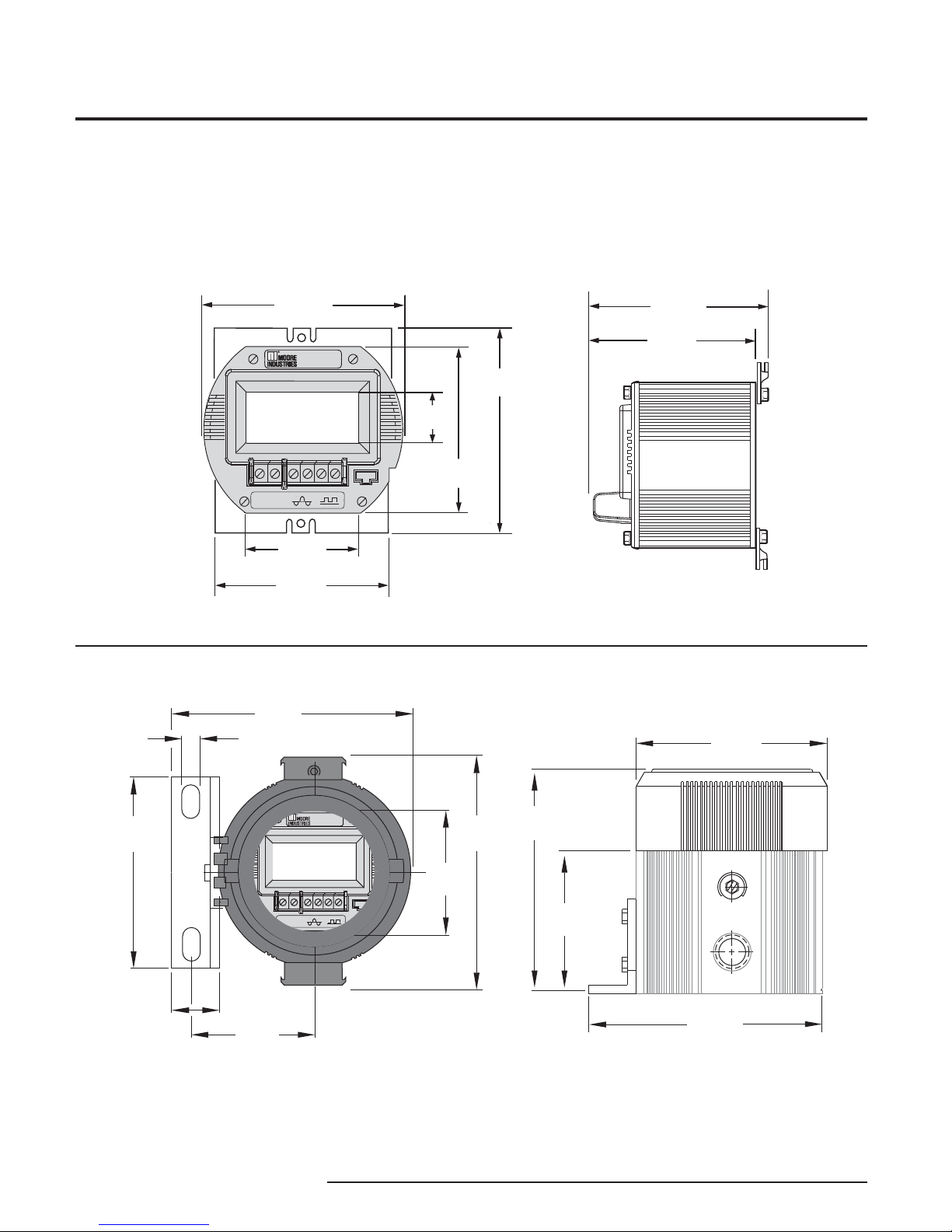
Figure 2. FDY Dimensions
Figure 3. BH Enclosure Dimensions
129mm
10mm
(5.06 in)
(0.38 in)
102mm
(4.00 in)
25mm
(1.00 in)
66mm
(2.60 in)
TOP VIEW
FDY
6027.8
HZ
–
+
–PS
+PS
0
0
COM
65mm
(2.55 in)
124mm
(4.90 in)
119mm
(4.70 in)
(3.00 in)
76mm
SIDE VIEW
102mm
(4.00 in)
GND
1/2 NPT
124mm
(4.90 in)
6 The Interface Solution Experts
Page 7
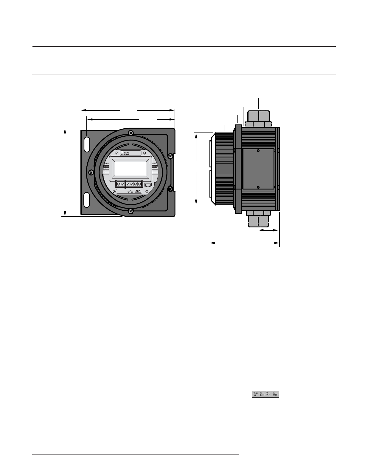
Figure 4. D-BOX Enclosure Dimensions
11 mm
4.65 in
13 mm
5.12 in
FDY
116mm
4.56 in
FDY
PC-Programmable Frequency
Transmitter and Display
CNDIT
FITTIN
DY
C
6027.8
HZ
CM
–
–PS
PS
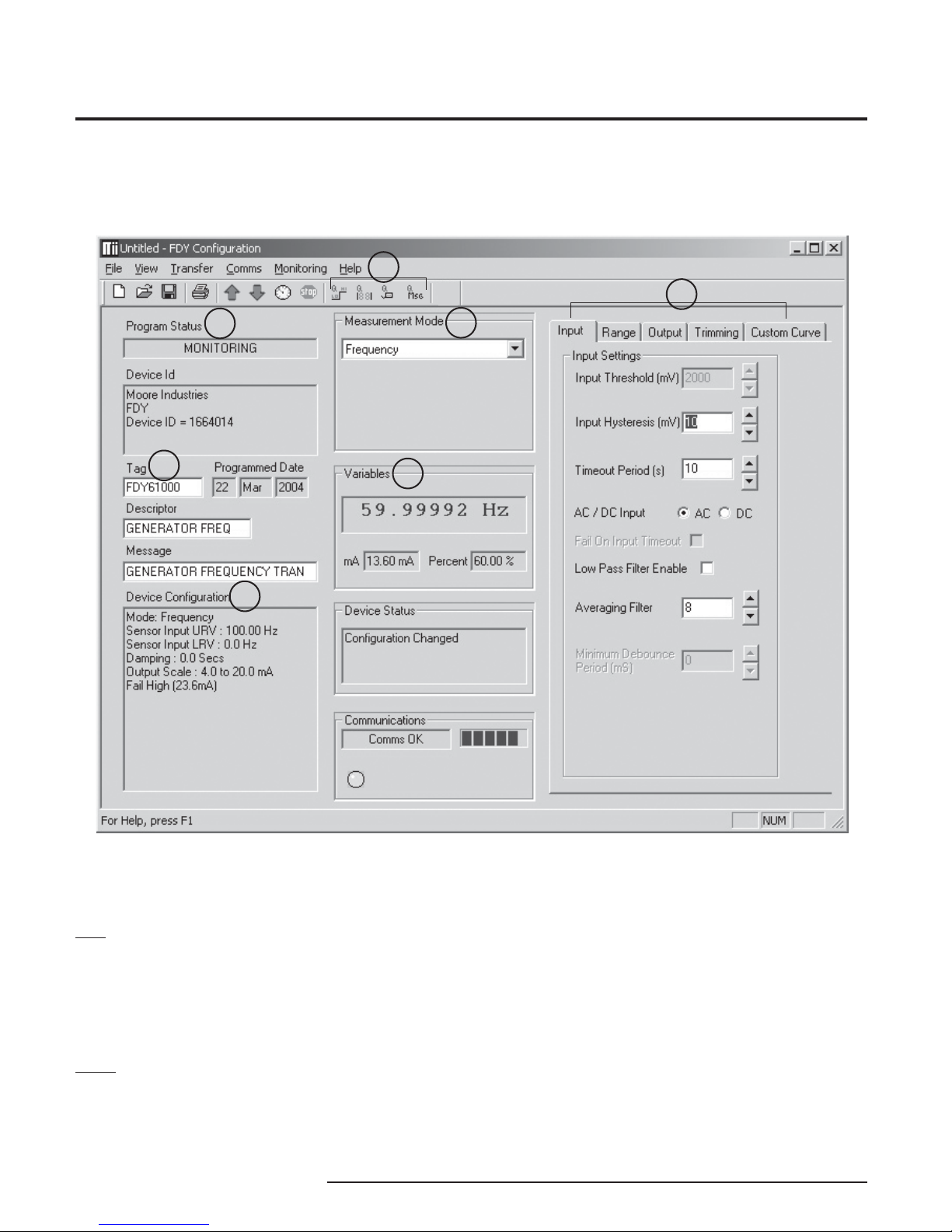
PC Confi guration Software
The FDY PC Confi guration Software is used to
program all of the FDY’s parameters. For detailed
information on how to use our confi guration software,
access our HelpMap Navigation System. The PC
Software is made up of these sections:
1. Program Status & Device ID–The Program
Status portion of the screen displays the activity of
the connected unit. It will show you if the unit is Idle,
Uploading, Downloading or Monitoring. Device ID
displays the type of device that is being polled and its
ID number.
2. Tag/Descriptor/Message–These boxes are used
to program a FDY with an individual tag, descriptor or
message used for easily identifying the unit. The
Programmed Date stores the last time that the unit’s
confi guration was updated.
3. Device Confi guration–Displays the current
confi guration of the attached FDY.
1mm
3.2 in
4mm
3.3 in
INST M NT
T
27mm
1. 5 in
4. Measurement Mode–The drop-down menu selects
which type of measurement the FDY will monitor.
5. Variables/Device Status/Communications–
These sections display the status of the FDY and its
process. The Variables section displays the input
to the FDY, FDY output and the percent of span.
The Device Status provides advanced diagnostic
information on the FDY. The Communications box
displays the status of the FDY’s communication with
the PC Program.
6. Input/Range/Output/Trimming/Custom Curve
Tabs–These tabs change the right side of the screen
to allow you to set the appropriate part of the FDY’s
confi guration. See corresponding sections of this
manual for additional information on these tabs.
7. Quickset Buttons –These buttons
allow you to program just one part of the FDY’s
confi guration program. From left to right, they
program: Fail Mode, Display Mode, Tag and Message.
The Interface Solution Experts 7
Page 8
FDY
PC-Programmable Frequency
Transmitter and Display
Figure 5. All of the FDY Operating Parameters can be set from the Main Screen of the Confi guration Program.
7
6
1
2
5
4
3
Default/Factory Confi gurations
The following are the default factory settings for your
unit:
Input:
Measurement Mode: Frequency 0-100Hz
Input Hysteresis: 10mV
Timeout Period: 10s
AC/DC Input: AC
Low Pass Filter: Disabled
Averaging Filter: 8
Minimum Debounce Period: 10mS
Scaling Disabled
Output:
4-20mA
Damping: 0s
Fail Mode: High (23.6mA)
Display Mode: Primary Variable
8 The Interface Solution Experts
Page 9
FDY
FDY
COM
+PS
0
+
–
–PS
0
6027.8
HZ
–
+
–+
POWER
SOURCE
12-42Vdc
MULTIMETER
4-20mA
–+
CALIBRATED
DC INPUT
SIMULATOR
FDY COMMUNICATION CABLE
803-040-26 FOR NON-ISOLATED
803-039-26 FOR ISOLATED
or Optional USB Cable 208-836-00
CALIBRATED
AC INPUT
SIMULATOR
OR
250 ohms
FREQ.
COUNTER
FREQ.
COUNTER
PC-Programmable Frequency
Transmitter and Display
Programming the FDY
All operating parameters of the FDY are set using
a PC, a serial communication cable and Moore
Industries’ Intelligent PC Confi guration software. When
the PC Confi guration program is loaded and running,
most of the parameters for the connected transmitter
are shown on a single screen. This makes it easy to
determine which aspects of transmitter operation need
to be changed to suit the application requirements.
Once the software settings are made, they are
downloaded to the transmitter in the form of a
confi guration fi le and stored in the non-volatile unit
memory. You can choose to save a backup copy of the
fi le on your PC hard drive or external media.
Program the FDY by connecting the FDY to the PC,
setting the appropriate parameters in the PC program,
and downloading the confi guration.
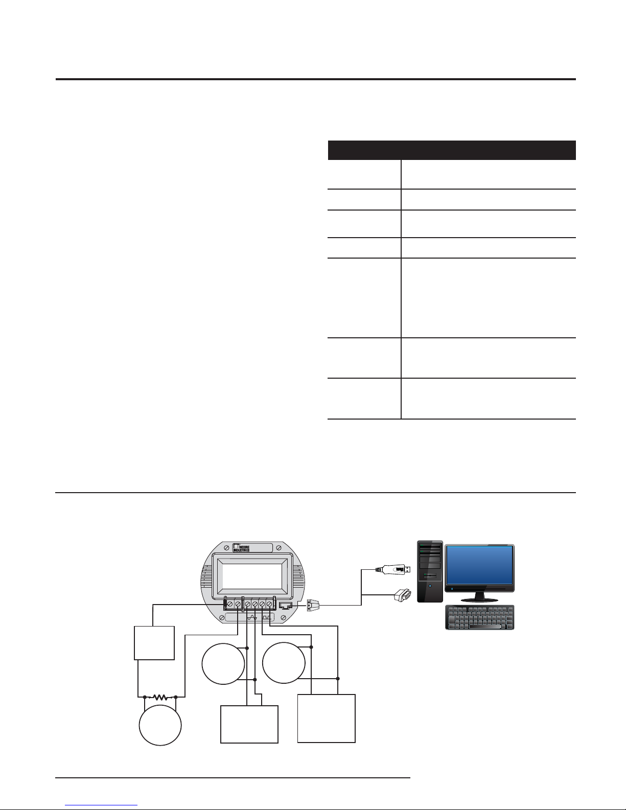
Connecting the FDY to the PC
The fi rst step in confi guring the FDY is connecting
the transmitter to the PC program and attaching the
appropriate input devices. Connect the FDY as shown
in Figure 6 below; refer to Table 9 for a description of
required equipment. After the FDY is confi gured, you
can begin programming the basic parameters.
Table 9. Assembling the Necessary Equipment
Device
Frequency Input
ulator
Sim
Power Supply
Precision Load
Resistor
Multimeter
Per
sonal
Computer
Communications
Cable
Communications
Software
Variable, accurate to ±0.005% of reading
12-42Vdc
250 ohms, ±0.01%
Accurate to ±0.025% of reading
Microsoft Windows based PC;
16Mb free RAM; 20MB free disk space on hard
drive
Microsoft Windows XP, Vista or 7
1 (one) serial port or one available USB port
(with optional USB cable)
Isolated cable P/N: 803-039-26
Non-isolated cable P/N: 803-040-26
or optional USB cable P/N: 208-836-00
Version 1.0 or greater,
part number: 750-75E05-01
Device
Figure 6. Connecting the FDY to the PC
The Interface Solution Experts 9
Page 10
FDY
PC-Programmable Frequency
Transmitter and Display
Programming the Basic Parameters
Programming the Basic Parameters involves selecting
the desired parameters in the PC Program, then
downloading those parameters to the FDY. Begin by
entering the device identifi cation and measurement
mode parameters into the confi guration software.
Device Identifi cation Information
The Tag (8 characters, maximum), Descriptor (16
characters, maximum) and Message (32 characters,
maximum) boxes allow you to assign a unique identity
to each FDY.
Measurement Mode
Select from Frequency, Period, Pulse Width High,
Pulse Width Low and Contact Closure. This selects
the variable to be measured and displayed. (Unless
a custom EGU is selected in the Custom Curve tab.)
(See Figure 5, section 4).
Programming the Input Parameters
When setting input parameters, please read the
following information for guidance. All input voltages
above 3V are internally clamped at 3V and all AC
signals are squared and measured at the zero
crossing. Therefore the settings for input threshold and
hysteresis assume a maximum input of 3V.
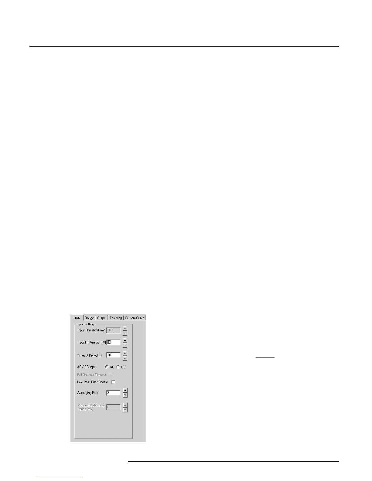
Use the Input tab in Figure 7 to enter the following
parameters:
AC / DC Input: Select the type of input the FDY will
measure.
Input Threshold: Input threshold is applicable to DC
inputs only. Input Threshold is the input voltage above
which the input is considered high. For input voltages
above 3V, it is recommended to set this to the default
setting of 2V (maximum is 2.5V). For input voltages
below 3V, it is recommended to set this to 2/3 of the
peak-to peak (p-p) input signal voltage plus the low
state signal voltage.
Input Hysteresis: This is the difference between high
and low voltage points at which the input circuit detects
changes of input state. For DC inputs this must be less
than the threshold. For example, if the threshold is set
for 2V, and the hysteresis is set for 1.2V, the FDY will
detect high for >2V and low for <0.8V.
- For DC input voltages above 3V, it is
recommended to set this to the default setting of
1.2V (maximum is 1.5V).
- For DC input voltages below 3V, it is
recommended to set this to 1/3 of the peak-to peak
(p-p) input signal voltage plus the low state signal
voltage.
- For AC inputs the hysteresis is used to minimise
noise interference. Above 3V, it is recommended to
set this to 150mV.
- For AC inputs below 3V, it is recommended to set
this to 10% of the signal voltage level.
Figure 7. Input Parameters Tab
10 The Interface Solution Experts
Timeout Period: The number of seconds that the
input will remain at lower range value before the FDY
declares a hardware error, if the Fail On Input Timeout
box is checked. The Timeout Period can be confi gured
at minimum of 0.5sec to a maximum of 600sec, factory
default is set to 10sec.
NOTE:
The timeout period must be set greater than the
Lower Range Value period if Fail On Input Time-out is
enabled.
Fail On Input Timeout: If your input is lower than the
allowed Lower Range Value and the Fail On Input
Timeout feature is enabled, Broken Wire (in the Device
Status section of the PC Program) or Broke Input (on
the FDY display) is declared after the set Timeout
Period has passed.
Page 11
FDY
PC-Programmable Frequency
Transmitter and Display
NOTE:
If the Lower Range Value is set to 0Hz in the Input
Range the Fail On Input Time-out feature will not be
available, the Lower Range Value must be set to a
value greater than zero to enable this feature (box
must be checked to apply feature) .
Low Pass Filter Enable: Reduces noise by fi ltering out
high frequency signals.
NOTE:
Moore Industries recommends having the Low-Pass
fi lter turned on when the upper input range value is
less than 150Hz (especially on the 10VAC - 250VAC
units).
Averaging Filter: Shows the number of readings
the FDY averages together to provide the displayed
reading. This can be used to compensate for bent
blades in a monitored turbine by setting the value to
equal the number of blades on the turbine. (i.e. if the
turbine has four blades, set the Averaging Filter to 4).
Minimum Debounce Period: Available only when
contact closure is selected in measurement mode.
This value eliminates noise from a contact closure
input, but lowers the maximum measurable frequency.
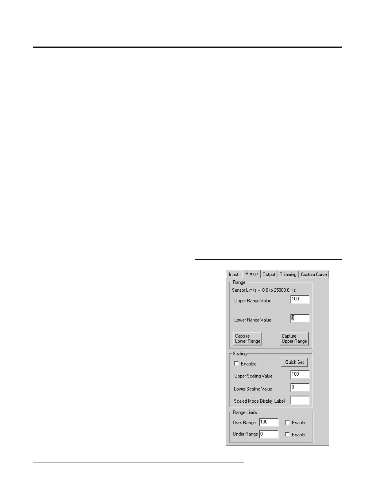
You are given the option of scaling your process
variable reading. To do this, click the Enabled check
box in the Scaling section. Scaling allows you to take
your process variable and manipulate the reading to a
more customized range.
• In the Upper Scaling Value text box, enter the
value you wish displayed when your input is at its
full range. Repeat the step for the value you wish
displayed when your input is at its zero value and
enter that into the Lower Scaling Value box.
At the Scaled Mode Display Label box, enter the
specifi c EGU (Engineering Unit) that you want as your
display.
• The Range Limits section allows you to designate
when the input will be considered bad (over or
under range). For example, if you have set the
Lower Range Value for 20, you can set the Under
Range for 10 and check the Enable box, allowing
the input to decrease below 10Hz before an error
is registered. In this case, the display shows
Under/Over range, and the output is in Failure
Mode (see Programming Output Parameters).
Figure 8. Range Parameters Tab
After selecting the input parameters, continue
by clicking the Range tab and proceeding to the
Programming the Range Parameters section.
Programming the Range Parameters
The Range tab permits you to set or capture the
acceptable input range and establish range limits.
• Use the Lower Range Value cell to set the input
value that will correspond to a 4mA output. In the
same way, use the Upper Range Value to set the
input value that corresponds to a 20mA output.
• Reverse the output (causing the output to increase
as the input decreases) by setting the Lower
Range Value higher than the Upper Range Value.
• The Capture Lower Range and Capture Upper
Range buttons permit you to trim the upper and
lower range of the sensor (if necessary). Just click
the appropriate button to begin trimming.
The Interface Solution Experts 11
Page 12
FDY
PC-Programmable Frequency
Transmitter and Display
Programming the Output
Parameters
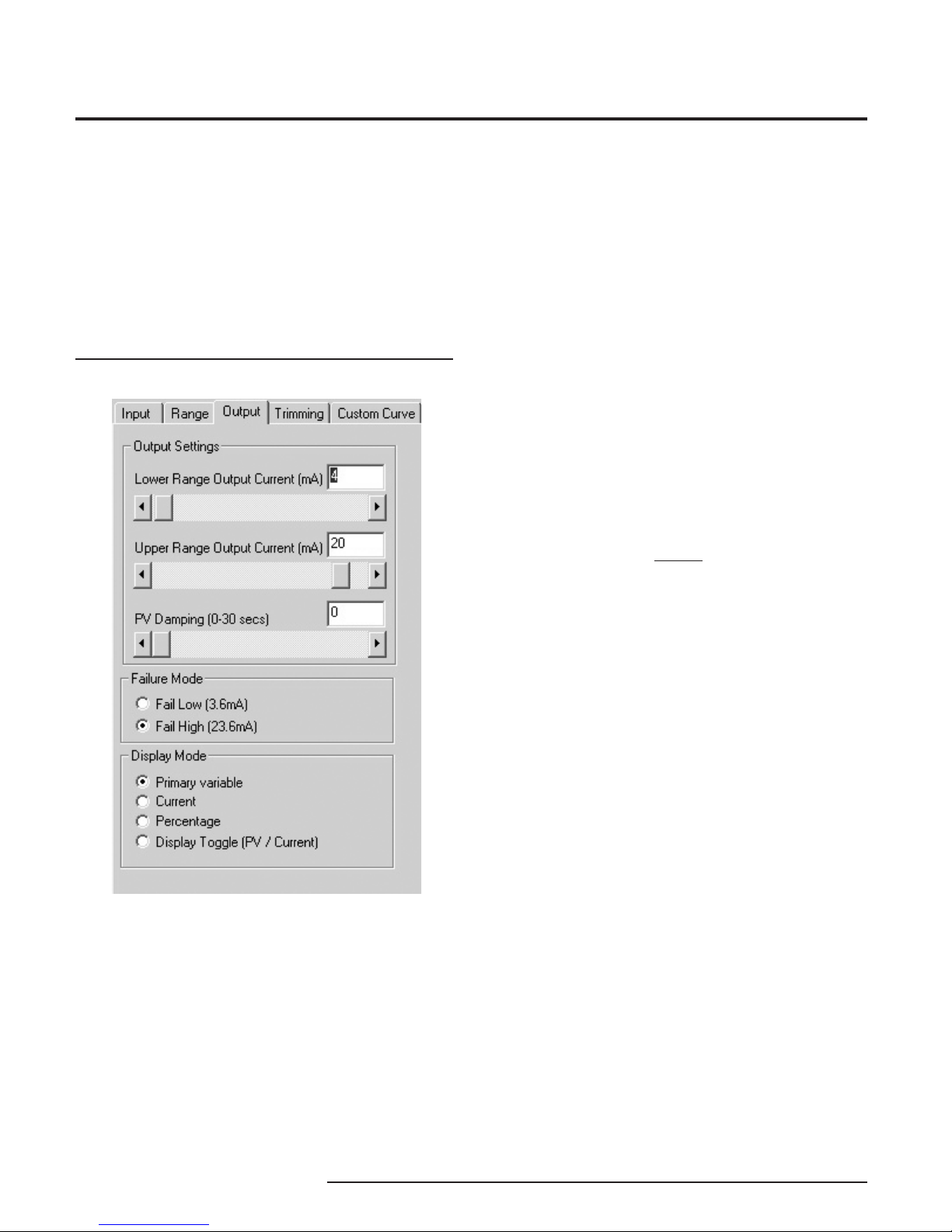
The Output section of the PC software is composed
of three sections: Output Settings, Failure Mode and
Display Mode. Use the functions of Output Settings to
set the current range from 3.8 to 21.6mA (usually
4-20mA). The minimum span is 4mA.
Figure 9. Output Parameters Tab
Output Settings
The output can be reversed (causing the output to
increase as the input decreases) by setting the Lower
Range Value in the Range tab as higher than the
Upper Range Value (See Figure 8).
PV (Primary Variable) Damping precisely reads the
input then specifi es an exponential change in the
output by 60% over the time set in the PV Damping
box. This reduces the effect of sudden spikes and
helps stop unnecessary alarms by smoothing the
reading.
Failure Mode
Failure Mode lets you set the output of the transmitter
when it is malfunctioning. It will either transmit a 3.6mA
(set to Fail Low) or a 23.6mA (set to Fail High) signal.
NOTE:
The Failure Mode has no effect unless one of the fail
conditions is active (i.e. Fail On Input Time-out or Over/
Under Range Limits).
Display Mode
Display Mode selects which variable will be displayed
on the transmitter’s display. Choose between Primary
Variable, Current, Percentage and Display Toggle.
(Display Toggle switches back and forth from the
primary variable to current and back in one-second
increments). The PC Program’s display is not changed
by changing the selection under the Display Mode.
12 The Interface Solution Experts
After the Range parameters have been selected, you
can continue on by clicking on the Trimming tab, and
proceeding to Programming the Trimming Parameters.
Page 13
FDY
PC-Programmable Frequency
Transmitter and Display
Programming the Trimming
Parameters
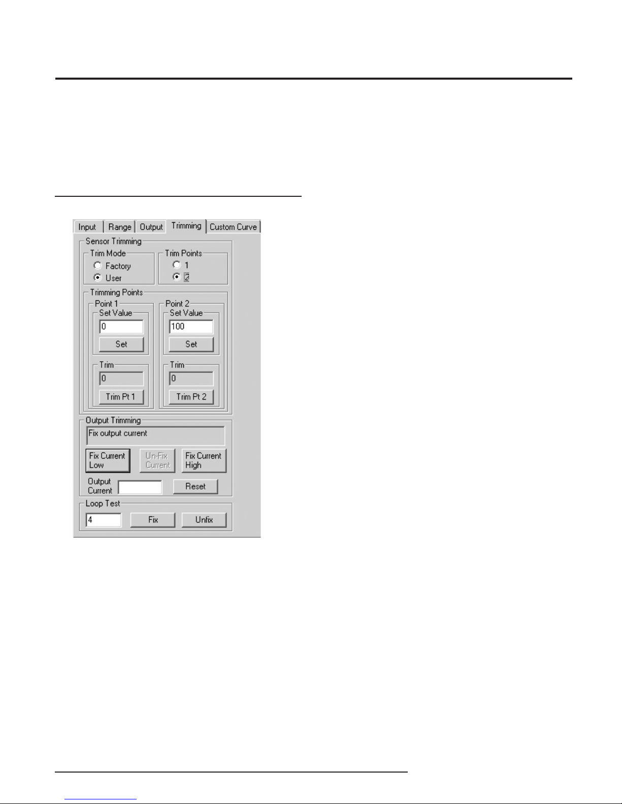
The Trimming tab includes Sensor (Input) Trimming,
Output Trimming and Loop Test functions.
Figure 10. Trimming Parameters Tab
Sensor Trimming
Sensor Trimming increases the measured accuracy of
your transmitter by matching the reading of its actual
input to either a calibrated source or the master device
to which it is transmitting. This causes the FDY’s
process variable and output to match its input.
Most transmitters can only trim at the 0% and 100%
points of the scale, but the FDY can trim any point
along the scale. Note that one-point trimming applies
an offset to the sensor reading, while two-point
trimming applies both an offset and gain.
Before you attempt to trim the FDY, ensure that the
correct sensor is attached to the transmitter, then go to
the Trimming tab as shown at the left, and:
1. Select the User radio button under Trim Mode, then
answer Ye s to the “Please confi rm that you want to do
this” prompt.
2. Select one or two trim points by clicking the
appropriate button under Trim Points.
3. Enter the value you want to trim into the Set Value
box under Point 1 and click Set. Apply the value you
entered in the Set Value section to the FDY. Click on
the Trim Pt 1 button. This matches the signal from the
sensor to the fi rst point you selected.
4. If you selected two trim points, enter the second
value that you want to trim into the Set Value box
under Point 2 and click Set. Then apply the value you
entered in the Point 2 box to the FDY. Click on the Trim
Pt 2 button. This matches the signal from the sensor to
the second point you selected.
5. You have now fi nished trimming your sensor and can
continue on to Output Trimming.
The Interface Solution Experts 13
Page 14

FDY
PC-Programmable Frequency
Transmitter and Display
Output Trimming
Output Trimming increases the accuracy of your
transmitter by matching the reading of its recorded
output to its actual output. Essentially, this means that
it will eliminate any error in the unit that is reading the
FDY’s output.
To start trimming the output, hook-up the transmitter
in the loop shown in Figure 6, and connect either a
multimeter (preferably), or the unit that will be reading
the FDY’s signal to the transmitter’s output.
1. Click the Fix Current Low button. This should cause
the FDY to output 4mA. If it is outputting a different
value, enter the value that the FDY is outputting (in
mA) into the Output Current box, then click Trim Low.
2. Check what your multimeter displays as the
transmitters output. If it is still not precisely 4mA, enter
it into the Output Current box again and clickTrim
Low again. Repeat until your multimeter displays an
acceptable reading.
3. When you are fi nished, click Un-Fix Current. After
doing this, the output will still be trimmed, but the
output will no longer be fi xed at 4mA.
Loop Test
Use the Loop Test to trim other instruments in the loop.
1. To begin the loop test, enter the mA value you want
the FDY to output to the Loop into the Loop Test text
box. Click Fix.
2. Monitor the effect of this on the other instruments in
the loop, and adjust accordingly.
3. If necessary, repeat steps 1 and 2 and enter a
different value in the Output Current box.
4. When you are fi nished, click Unfi x.
After the trimming parameters have been selected,
you can continue on by either downloading the
confi guration or clicking the Custom Curve tab, and
proceeding to the Programming the Custom Curve
Parameters section.
4. Continue by clicking the Fix Current High button.
This should cause the FDY to output 20mA. If the
output is a different value, enter it into the Output
Current box, then click Trim High.
5. Check what your multimeter displays as the
transmitters output. If it is still not precisely 20mA,
enter it into the Output Current again and click Trim
High again. Repeat until your multimeter displays an
acceptable reading.
6. When you are fi nished, click Un-Fix Current. After
doing this, the output will still be trimmed, but the
output will no longer be fi xed at 20mA.
NOTE:
Clicking the RESET button will completely undo output
trimming.
14 The Interface Solution Experts
Page 15
FDY
PC-Programmable Frequency
Transmitter and Display
Programming the Custom Curve
Parameters
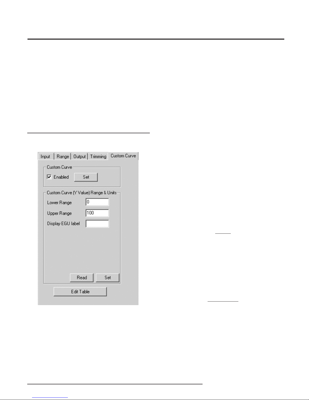
The Custom Curve section of the confi guration
software allows you to setup your own custom curve
table with up to 128 points. In effect, this allows you
to tell the transmitter what it should output when it
receives a certain input. Use the Custom Curve tab for
customizing the display’s engineering units, reversing
the output, signal limiting and creating custom curves.
Figure 11. Custom Curve Parameters Tab
Follow these directions to setup your custom curve
table:
1. Check the Enabled box in the Custom Curve
section. Click the Set button and wait for the
transmitter to fi nish downloading the information.
2. Input the Lower Range and the Upper Range
into the appropriate boxes. The point you enter in
the Lower Range will become the zero point of the
transmitter, and the transmitter will send out a 4mA
signal (or the selected output signal, if the zero output
is set at a value other than 4mA) when this point is
reached. Likewise, the point you enter into the Upper
Range will cause the transmitter to output 20mA (or full
output signal, if different) when that point is reached.
3. Enter the desired engineering unit into the
Display EGU label box. This will control what type of
engineering unit (up to 5 alphanumeric characters,
excluding symbols) is displayed by the Confi guration
Software and on the FDY’s display.
4. Click Set to download all of the information to the
transmitter.
NOTE:
“Read” will upload the information from the transmitter
to the confi guration program. This can be used to
take the last table that you have downloaded to the
transmitter and enter it into the PC Confi guration
Software.
5. Click Edit Table to begin creating your own custom
curve table (see next page for instructions).
IMPORTANT:
Once you enable the custom curve, you must edit the
table in order for your transmitter to work properly.
The Interface Solution Experts 15
Page 16

FDY
PC-Programmable Frequency
Transmitter and Display
Editing the Custom Curve Table
To edit custom table points, click Edit Table in the
Custom Curve tab, then follow the directions below.
1. If you have already written a custom table in
Microsoft® Excel (and saved it in a .csv format) or in
our PC Confi guration Software, you can open it from
the Edit Table menu. Go to File (at the top, left corner
of the screen, on the command bar), and click Open,
then select the appropriate fi le.
2. If you have NOT already written a custom table,
begin writing one by clicking the Edit Table button and
selecting the number of points you would like to defi ne.
Do this in the Number of Points section.
3. Make sure that the Custom Curve Enabled box is
checked. If not, check it and click the Set button.
4. Fill in the values in the X and Y columns. X is the
input column–it represents the value that is input into
the FDY. Y is the output column–it represents the
value (in engineering units) that the transmitter will
output when the value in the X column is input. It is
also the value that will be displayed in the PC Software
and on the FDY display. If an input falls in between two
X values, then the output will be scaled to match the
percentage difference between the two X points.
5. When you have fi lled in all of the custom curve
points, click Download. This will download the
information from the PC Confi guration Software to the
transmitter. If you later want to retrieve the fi le from
the transmitter to the PC Confi guration Software, you
can reattach the transmitter and click Upload. You are
now done confi guring your custom table, and if you
have made changes to other parts of the confi guration
program, you are ready to download the confi guration
fi le.
Downloading the Confi guration File
After the confi guration has been set to your
satisfaction, it can be downloaded to the unit by
selecting Download from the Transfer Menu or by
pressing the Download button ( ) on the status bar.
Downloading the confi guration displayed in the PC
program overwrites the unit’s current confi guration.
Downloading the confi guration to the FDY may take
up to 30 seconds to complete. It is important to let the
sequence fi nish before taking any other action.
Once completed, the Device Confi guration portion of
the screen (in the bottom-left corner) will change to
match the confi guration listed on the rest of the screen.
The status indicator in the top left hand corner of the
view will then indicate the program has reverted back
to its idle mode.
Installing the FDY
Moore Industries suggests installing the FDY by fi rst
mounting the unit in its intended application, then
making the electrical connections to input, output and
power.
Mounting
The FDY is built in a HP housing and can be shipped
with one of our durable fi eld-mount enclosures, such
as the BH or D-BOX. Use the BH for tough, explosionproof protection, or the D-BOX for areas where you
need durable, reliable protection for your display.
The FDY is also versatile enough to be mounted on
a surface, relay track, pipe or inside one of our fi eld
enclosures.
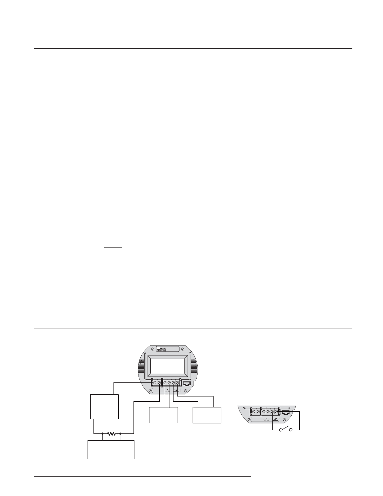
Electrical Connections
The connections for the various single FDY inputs are
shown in the following diagram.
16 The Interface Solution Experts
CE Conformity
Installation of any Moore Industries’ products that carry
the CE certifi cation (Commission Electrotechnique)
must adhere to the guidelines in Installing the FDY
in order to meet the requirements set forth in the
applicable EMC (Electromagnetic Compatibility)
directive (EN 61326). Consult the factory for the most
current information on products that have been CE
certifi ed.
Page 17
FDY
PC-Programmable Frequency
Transmitter and Display
Recommended Ground
Wiring Practices
Moore Industries recommends the following ground
wiring practices:
• Any Moore Industries product in a metal case or
housing should be grounded.
• The protective earth conductor must be connected
to a system safety earth ground before making any
other connections.
• All input signals to, and output signals from,
Moore Industries’ products should be wired using
a shielded, twisted pair wiring technique. Shields
should be connected to an earth or safety ground.
• For the best shielding, the shield should be run
all the way from the signal source to the receiving
device. (see Note below)
• The maximum length of unshielded input and
output signal wiring should be 2 inches.
Note:
Some of Moore Industries’ instruments can be
classifi ed as receivers (IPT2, IPX2, etc.) and
some can be classifi ed as transmitters (TRX,
TRY, etc.) while some are both a receiver
and a transmitter (SPA
your shield ground connections should be
appropriate for the type of signal line being
shielded. The shield should be grounded at
the receiver and not at the signal source.
2
, HIM, etc). Hence,
Customer Service
If service assistance is ever required for one of the
FDYs in your application, refer to the back cover of this
manual for the telephone numbers to Moore Industries
STAR Center customer service department.
If possible, make a note of the model number of the
offending unit before calling. For fastest assistance, try
to gather information on the unit(s) serial number and
the job and purchase order number under which it was
shipped.
Figure 12. Hook-Up Diagram for Installing the FDY into the Application
+
POWER
SOURCE
10-42Vdc
–
250 ohms
–+
READOUT DEVICE,
CONTROL SYSTEM
FDY
6027.8
HZ
–
+
–PS
+PS
0
0
AC INPUT
COM
CONTACT CLOSURE
INPUT HOOK-UP
–+
DC INPUT
OR
The Interface Solution Experts 17
OR
–PS
+PS
0
COM
–
+
0
Page 18

FDY
PC-Programmable Frequency
Transmitter and Display
Appendix A: Intrinsically-Safe
Applications
This page contains information for the FDY instrument
when used within an intrinsically-safe system.
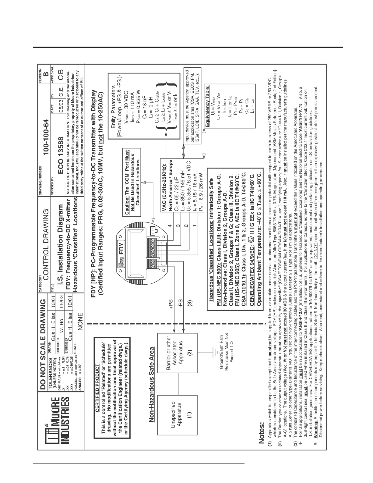
The diagram on the following page must be used for
units that are to operate in areas requiring intrinsicallysafe instrumentation.
Refer to the Special Conditions outlined below before
proceeding with installation.
Special Conditions of Use
The following instructions must be adhered to when
the FDY is used in hazardous ‘Classifi ed’ locations and
potentially explosive atmospheres.
1. The FDY Power Supply/Output must only be
connected to a intrinsically-safe certifi ed Barrier or other
associated apparatus.
2. Entity parameters must be adhered to, as specifi ed
in the following diagram located on next page.
18 The Interface Solution Experts
Page 19
FDY
PC-Programmable Frequency
Transmitter and Display
The Interface Solution Experts 19
Page 20

EC Declaration of Conformity
Moore Industries-International, Inc. Date Issued: 21 Oct. 2013
16650 Schoenborn Street No. 100-100-204 Rev. C
North Hills, CA 91343-6196 U.S.A. Page 1 of 2
Equipment Description:
PC-Programmable Frequency-to-DC Transmitter with Display
Model FDY / * / * / * / * / *
* Indicates any input, output, power, options and housing as stated in the product data sheet.
Directive:
2004/108/EC (EMC)
Specifications Conformed To:
EN 61326-1:2006
Equipment Description:
PC-Programmable Frequency-to-DC Transmitter with Display
Model FDY / * / * / * / * / HP
* Indicates any input, output, power and options as stated in the product data sheet.
Directive:
94/9/EC (ATEX)
Provisions of the Directive Fulfilled by the Equipment:
Group II Category 1G EEx ia IIC T4
Notified Body for EC-Type Examination:
LCIE [Notified Body Number 0081]
33, av du Général Leclerc
92260 Fontenay-aux-Roses - France
EC-Type Examination Certificate:
LCIE 03 ATEX 6172 X
Standards and Technical Specifications Used*:
EN 50014:1997 + Amds 1 & 2
EN 50020:2002 Electrical apparatus for potentially explosive atmospheres. Intrinsic safety ”i”.
*Note: The Requirements of these Standards were reviewed against Technical Standards
EN 60079-0:2009
EN 60079-11:2007 Explosive atmospheres Part 11: Equipment protection by intrinsic safety ”i”
and there are no significant changes relevant to this equipment or affecting the latest technical
knowledge for the product identified on this declaration.
Electrical equipment for measurement, control and laboratory use - EMC requirements
Electrical apparatus for potentially explosive atmospheres. General requirements.
Explosive atmospher es Part 0: Equipm ent - General requirements
Page 21

EC Declaration of Conformity
Moore Industries-International, Inc. Date Issued: 21 Oct. 2013
16650 Schoenborn Street No. 100-100-204 Rev. C
North Hills, CA 91343-6196 U.S.A. Page 2 of 2
Equipment Description:
PC-Programmable Frequency-to-DC Transmitter with Display
Model FDY / * / * / * / * / BH**E or SB**E
* Indicates any input, output, power and options as stated in the product data sheet.
**Indicates any BH or SB Enclosure with the ‘E’ suffix.
Directive:
94/9/EC (ATEX)
Provisions of the Directive Fulfilled by the Equipment:
Group II Category 2G Ex d IIC T6;
Notified Body for EC-Type Examination:
ISSeP [Notified Body Number 0492]
Zoning A. Schweitzer 7340
Colfontaine, Belguim
EC-Type Examination Certificate:
ISSeP 08 ATEX 033 X
Technical Standards Used:
EN 60079-0:2006
EN 60079-1:2007 Explosive atmospheres Part 1: Equipment protection by flameproof enclosures "d"
EN 61241-0:2006 Electrical apparatus for use in the presence of combustible dust - Part 0: General requirements
EN 61241-1:2004
Notified Body for Quality Assurance:
SIRA [Notified Body Number 0518]
Rake Lane, Eccleston,
Chester, Cheshire,
CH4 9JN, England
On Behalf of Moore Industries-International, Inc., I declare that, on the date the equipment accompanied by this
declaration is placed on the market, the equipment conforms with all technical and regulatory requirements of
the above listed directives.
Signature: Deanna Esterwold, Quality Manager
Group II Category 2D Ex tD A21 IP66 T85˚C
Explosive atmospheres Part 0: Equipment - General requirements
Electrical apparatus for use in the presence of combustible dust - Part 1: Protection by enclosures "tD"
Page 22

RETURN PROCEDURES
To return equipment to Moore Industries for repair, follow these four steps:
1. Call Moore Industries and request a Returned Material Authorization (RMA) number.
Warranty Repair –
If you are unsure if your unit is still under warranty, we can use the unit’s serial number
to verify the warranty status foryou over the phone. Be sure to include the RMA
number on all documentation.
Non-Warranty Repair –
If your unit is out of warranty, be prepared to give us a Purchase Order number when
you call. In most cases, we will be able to quote you the repair costs at that time. The
repair price you are quoted will be a “Not To Exceed” price, which means that the
actual repair costs may be less than the quote. Be sure to include the RMA number on
all documentation.
2. Provide us with the following documentation:
a) A note listing the symptoms that indicate the unit needs repair
b) Complete shipping information for return of the equipment after repair
c) The name and phone number of the person to contact if questions arise at the factory
3. Use suffi cient packing material and carefully pack the equipment in a sturdy shipping container.
4. Ship the equipment to the Moore Industries location nearest you.
The returned equipment will be inspected and tested at the factory. A Moore Industries representative will contact the person designated on your documentation if more information is
needed. The repaired equipment, or its replacement, will be returned to you in accordance
with the shipping instructions furnished in your documentation.
WARRANTY DISCLAIMER
THE COMPANY MAKES NO EXPRESS, IMPLIED OR STATUTORY WARRANTIES (INCLUDING ANY WARRANTY OF MERCHANTABILITY OR
OF FITNESS FOR A PARTICULAR PURPOSE) WITH RESPECT TO ANY
GOODS OR SERVICES SOLD BY THE COMPANY. THE COMPANY DISCLAIMS ALL WARRANTIES ARISING FROM ANY COURSE OF DEALING
OR TRADE USAGE, AND ANY BUYER OF GOODS OR SERVICES FROM
THE COMPANY ACKNOWLEDGES THAT THERE ARE NO WARRANTIES
IMPLIED BY CUSTOM OR USAGE IN THE TRADE OF THE BUYER AND
OF THE COMPANY, AND THAT ANY PRIOR DEALINGS OF THE BUYER
WITH THE COMPANY DO NOT IMPLY THAT THE COMPANY WARRANTS
THE GOODS OR SERVICES IN ANY WAY.
ANY BUYER OF GOODS OR SERVICES FROM THE COMPANY
AGREES WITH THE COMPANY THAT THE SOLE AND EXCLUSIVE REMEDIES FOR BREACH OF ANY WARRANTY CONCERNING THE GOODS OR
SERVICES SHALL BE FOR THE COMPANY, AT ITS OPTION, TO REPAIR
OR REPLACE THE GOODS OR SERVICES OR REFUND THE PURCHASE
PRICE. THE COMPANY SHALL IN NO EVENT BE LIABLE FOR ANY CONSEQUENTIAL OR INCIDENTAL DAMAGES EVEN IF THE COMPANY FAILS
IN ANY ATTEMPT TO REMEDY DEFECTS IN THE GOODS OR SERVICES
, BUT IN SUCH CASE THE BUYER SHALL BE ENTITLED TO NO MORE
THAN A REFUND OF ALL MONIES PAID TO THE COMPANY BY THE BUYER
FOR PURCHASE OF THE GOODS OR SERVICES.
ANY CAUSE OF ACTION FOR BREACH OF ANY WARRANTY BY
THE COMPANY SHALL BE BARRED UNLESS THE COMPANY RECEIVES FROM THE BUYER A WRITTEN NOTICE OF THE ALLEGED
DEFECT OR BREACH WITHIN TEN DAYS FROM THE EARLIEST DATE
ON WHICH THE BUYER COULD REASONABLY HAVE DISCOVERED
THE ALLEGED DEFECT OR BREACH, AND NO ACTION FOR THE
BREACH OF ANY WARRANTY SHALL BE COMMENCED BY THE
BUYER ANY LATER THAN TWELVE MONTHS FROM THE EARLIEST
DATE ON WHICH THE BUYER COULD REASONABLY HAVE DISCOVERED THE ALLEGED DEFECT OR BREACH.
RETURN POLICY
For a period of thirty-six (36) months from the date of shipment, and under
normal conditions of use and service, Moore Industries (“The Company”)
will at its option replace, repair or refund the purchase price for any of its
manufactured products found, upon return to the Company (transportation
charges prepaid and otherwise in accordance with the return procedures
established by The Company), to be defective in material or workmanship.
This policy extends to the original Buyer only and not to Buyer’s customers
or the users of Buyer’s products, unless Buyer is an engineering contractor
in which case the policy shall extend to Buyer’s immediate customer only.
This policy shall not apply if the product has been subject to alteration,
misuse, accident, neglect or improper application, installation, or operation.
THE COMPANY SHALL IN NO EVENT BE LIABLE FOR ANY INCIDENTAL
OR CONSEQUENTIAL DAMAGES.
United States • [email protected]
Tel: (818) 894-7111 • FAX: (818) 891-2816
Australia • [email protected]
Tel: (02) 8536-7200 • FAX: (02) 9525-7296
© 2013 Moore Industries-International, Inc.
Belgium • [email protected]
Tel: 03/448.10.18 • FAX: 03/440.17.97
The Netherlands • [email protected]
Tel: (0)344-617971 • FAX: (0)344-615920
Specifi cations and Information subject to change without notice.
China • [email protected]
Tel: 86-21-62491499 • FAX: 86-21-62490635
United Kingdom • [email protected]
Tel: 01293 514488 • FAX: 01293 536852
 Loading...