

Page 1
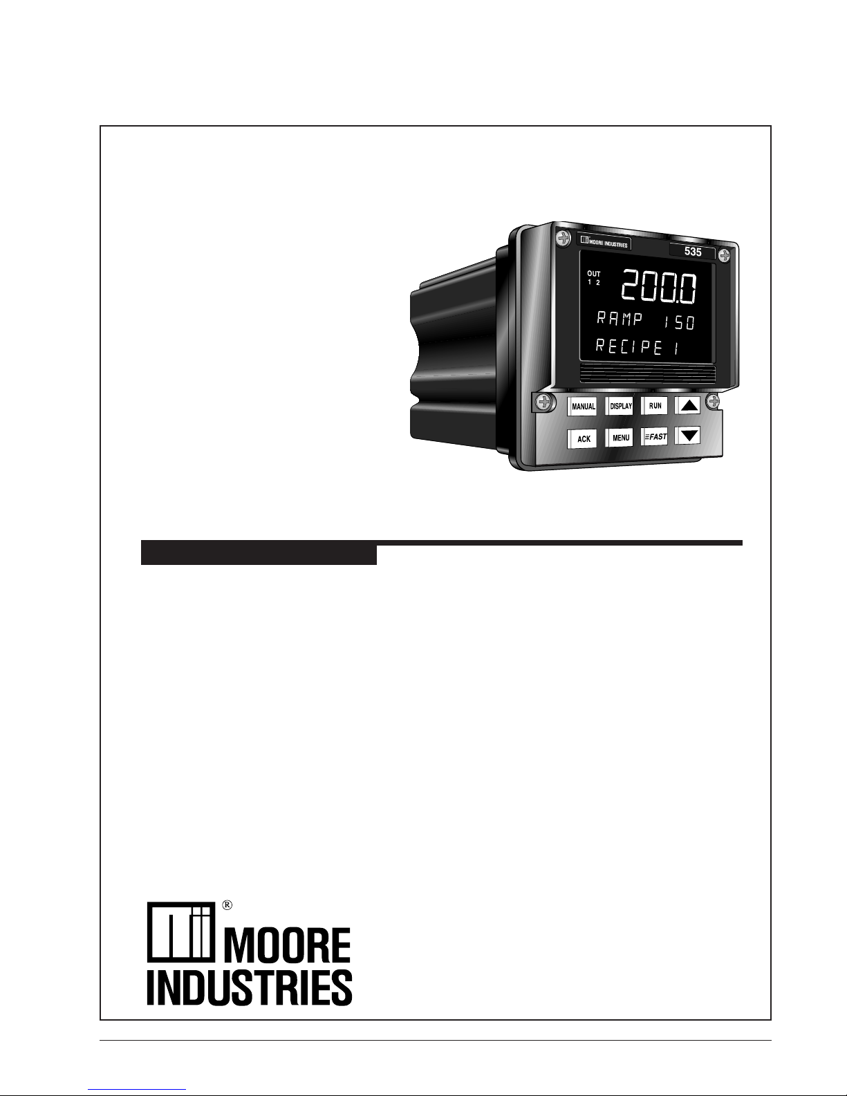
535
PROFILER
5 3 5 P R O F I L E R
1/4 DIN PROFILE CONTROLLER
USER'S MANUAL
M535-PROF V6, © JULY 20
17
Page 2

Isolation Block Diagram
535-PROF User's Manual Appendix 7 A-23
Page 3

TABLE OF CONTENTS
CHAPTER 1
INTRODUCTION ............................................................................... 1
535 Profile Controller Modes .............................................................. 1
Order Code, Packaging Information ................................................... 2
Where to Go Next ............................................................................... 2
Text Formatting in this Manual ........................................................... 2
CHAPTER 2
BASIC INTERFACE .......................................................................... 4
Displays ............................................................................................ 4
Icons (Lit) .......................................................................................... 5
Keys.................................................................................................. 5
Basic Profile Controller Operating Procedures .................................... 7
To Enter the RECIPE SET UP Mode .......................................... 7
To Enter the SET UP Mode ....................................................... 7
To Run a Recipe ........................................................................ 7
To Hold a Recipe ....................................................................... 7
To Abort a Recipe and Switch to Manual Control ........................ 7
To Abort a Recipe and Control to the Idle Setpoint ...................... 7
To Display the Setpoint (SP) while a Recipe Is Running ............. 8
To Display the Recipe Number .................................................. 8
Basic Process Controller Operating Procedures ................................. 8
To Select/Change a Setpoint ..................................................... 8
To Change from Auto to Manual Control (Bumpless Transfer) ..... 8
To Change from Manual to Auto ................................................. 8
To Change Manual Output Values ............................................. 8
To Override Security ................................................................. 8
To Display Control Output Value ................................................ 9
To Display the Active PID Set ................................................... 9
Alarm Operation ................................................................................. 9
Alarm Indication ........................................................................ 9
To Acknowledge an Alarm(s) ................................................... 10
Latching Alarms ...................................................................... 10
Limit Sequence ....................................................................... 10
More On Alarms ...................................................................... 10
Table of Contents
PAGE
About This Manual:
Throughout this User’s Manual
information appears along the
margins (NOTE: CAUTION! and
WARNING!). Please heed these
safety and good practice notices for
the protection of you and your
equipment.
CHAPTER 3
INSTALLATION .............................................................................. 11
Mounting the Controller .................................................................... 11
Wiring .............................................................................................. 12
AC Power Input ....................................................................... 13
Process Variable Input ............................................................ 13
Digital Input(s) ......................................................................... 16
1. Digital Inputs with a Switch or Relay ................................ 16
2. Digital Inputs with an Open Collector ............................... 16
Remote Setpoint Option .......................................................... 16
Output Modules ....................................................................... 17
1. Mechanical Relay Output ................................................ 17
2. Solid State Relay (Triac) Output ...................................... 17
535-PROF User's Manual Table of Contents i
Page 4

Table of Contents
CHAPTER 3
INSTALLATION (CONTINUED)
Output Modules
3. DC Logic (SSR Drive) Output .......................................... 18
4. Milliamp Output .............................................................. 18
5. Position Proportioning Output ......................................... 18
Serial Communications ........................................................... 19
Limit Control ............................................................................ 20
CHAPTER 4
HARDWARE SET UP ...................................................................... 21
Hardware Input Types ...................................................................... 21
The Process Variable ....................................................................... 21
The Remote Setpoint ....................................................................... 22
Mechanical Relays .......................................................................... 22
Accessing and Changing Jumpers ................................................... 23
Adding and Changing Output Modules .............................................. 24
Special Communications Module ..................................................... 26
CHAPTER 5
SOFTWARE CONFIGURATION ...................................................... 27
Menus ............................................................................................. 27
Parameters ...................................................................................... 29
Configuration and Operation ............................................................. 29
Where to Go Next ............................................................................. 29
Software Menus and Parameters ..................................................... 31
CONFIG.................................................................................. 31
REC. CONF. ........................................................................... 37
PV1 INPUT ............................................................................. 39
PV2 INPUT ............................................................................. 41
CUST. LINR. ........................................................................... 43
CONTROL .............................................................................. 44
ALARMS................................................................................. 46
REM. SETPT. ......................................................................... 50
RETRANS. ............................................................................. 51
SELF TUNE ............................................................................ 53
SPECIAL ................................................................................ 54
SECURITY ............................................................................. 56
SER. COMM. .......................................................................... 57
RECIPE # ............................................................................... 58
Parameter Value Charts ................................................................... 61
PAGE
ii Table of Contents 535-PROF User's Manual
CHAPTER 6
TUNING .......................................................................................... 71
Overview ......................................................................................... 71
Tuning Parameters .......................................................................... 72
Tuning Value Chart .......................................................................... 76
Self Tune Messages and Troubleshooting ........................................ 78
CHAPTER 7
APPLICATIONS .............................................................................. 79
A. Profile Control.............................................................................. 79
Software Configuration ............................................................ 80
Digital Inputs ........................................................................... 84
Page 5

Table of Contents
CHAPTER 7
APPLICATIONS (CONTINUED)
A. Profile Control
Master/Slave Operation ........................................................... 84
Hardware Configuration ....................................................... 85
B. Control Type ................................................................................ 85
Software Configuration ............................................................ 85
C. Alarms ........................................................................................ 86
Software Configuration ............................................................ 86
D. Duplex Control ............................................................................. 90
Hardware Configuration ........................................................... 90
Software Configuration ............................................................ 90
Duplex Output State Examples ............................................... 91
Duplex with Reverse and Direct Acting Outputs ................... 91
Duplex with Direct and Reverse Acting Outputs ................... 91
Duplex with 2 Reverse Acting Outputs ................................. 92
Duplex with a Gap Between Outputs .................................... 92
Duplex with a Overlapping Outputs and Output Limits .......... 93
Duplex with Various Relative Gain Settings ......................... 93
Duplex with One On/Off Output ........................................... 94
Duplex with Two On/Off Outputs ......................................... 94
E. Slidewire Position Proportioning Control ....................................... 95
Hardware Configuration ........................................................... 95
Software Configuration ............................................................ 95
F. Velocity Position Proportioning Control ........................................ 96
Hardware Configuration ........................................................... 96
Software Configuration ............................................................ 96
G. Staged Outputs ........................................................................... 97
Hardware Configuration ........................................................... 97
Software Configuration ............................................................ 97
H. Retransmission ........................................................................... 97
Hardware Configuration ........................................................... 97
Software Configuration ............................................................ 97
I. Digital Inputs................................................................................. 98
Hardware Configuration ........................................................... 98
Software Configuration ............................................................ 98
Basic Operating Procedures .................................................. 100
J. Remote Setpoint ........................................................................ 100
Hardware Configuration ......................................................... 100
Software Configuration .......................................................... 100
Basic Operating Procedures .................................................. 101
K. Multiple Setpoints ...................................................................... 101
Software Configuration .......................................................... 101
Basic Operating Procedures .................................................. 101
L. Multiple Sets of PID Values ....................................................... 101
Software Configuration .......................................................... 101
Basic Operating Procedures .................................................. 102
Using with Adaptive and Pretune ........................................... 102
M. Powerback ................................................................................ 102
Software Configuration .......................................................... 103
N. Self Tune— Powertune® ........................................................... 103
Pretune ................................................................................. 103
Adaptive Tune ....................................................................... 103
PAGE
535-PROF User's Manual Table of Contents iii
Page 6

Table of Contents
CHAPTER 7
APPLICATIONS (CONTINUED)
N. Self Tune—Powertune®
Software Configurations ........................................................ 104
Pretune by Itself................................................................ 104
Pretune Type 1 & Adaptive Tune ....................................... 104
Pretune Type 2 or 3 & Adaptive Tune ................................ 106
Adaptive Tune by Itself ..................................................... 106
Self Tuning with Multiple Sets of PID ................................. 108
Self Tune with Time Proportioning Outputs ........................ 108
Self Tune with Control Valves ........................................... 108
O. Ramp-to-Setpoint ...................................................................... 109
Software Configuration .......................................................... 109
P. Input Linearization ..................................................................... 109
Thermocouple and RTD Linearization .................................... 109
Square Root Linearization ...................................................... 109
Hardware Configuration ..................................................... 110
Software Configuration ...................................................... 110
Custom Linearization ............................................................. 110
Software Configuration ...................................................... 110
Q. Load Line .................................................................................. 111
R. Security .................................................................................... 111
Software Configuration .......................................................... 111
Basic Operating Procedures .................................................. 112
S. Reset Inhibition ......................................................................... 112
Software Configuration .......................................................... 112
T. Process Variable Reading Correction ......................................... 112
U. Serial Communications .............................................................. 113
Hardware Configuration ......................................................... 113
Software Configuration .......................................................... 113
V. Cascade Control ........................................................................ 114
Hardware Configuration ......................................................... 116
Software Configuration .......................................................... 116
Tuning Cascade Control ........................................................ 116
W. Ratio Control ............................................................................. 117
Hardware Configuration ......................................................... 118
Software Configuration .......................................................... 118
PAGE
iv Table of Contents 535-PROF User's Manual
Page 7

Table of Contents
APPENDIX 1
MENU FLOWCHARTS .. .... .............................................................A-1
APPENDIX 2
PARTS LIST .................................................................................. A-3
APPENDIX 3
TROUBLESHOOTING ................................................................... A-4
APPENDIX 4
CALIBRATION ............................................................................... A-6
Preparation For All Input Calibrations .............................................. A-7
Thermocouple Cold Junction Calibration ......................................... A-8
Analog Milliamp Input Calibration .................................................... A-8
Milliamp Output Calibration ............................................................. A-9
Reset Menu Data .......................................................................... A-10
Hardware Scan ..................................................................... A-11
Slidewire Test ............................................................................... A-11
Quick Calibration Procedure .......................................................... A-11
APPENDIX 5
SPECIFICATIONS ....................................................................... A-12
APPENDIX 6
GLOSSARY ................................................................................. A-17
APPENDIX 7
ISOLATION BLOCK DIAGRAM .................................................... A-22
PAGE
535-PROF User's Manual Table of Contents v
Page 8

Table of Contents
LIST OF FIGURES
PAGE
Figure 2.1 ....... Operator Interface ................................................................ 4
Figure 2.2 ....... Before and After Acknowledging An Alarm ............................. 9
Figure 3.1 ....... Instrument Panel & Cutout Dimensions ............................... 11
Figure 3.2 ....... Attaching Mounting Collar................................................... 11
Figure 3.3 ....... All 535-PROF Terminal Assignments .................................. 12
Figure 3.4 ....... AC Power Input Terminals .................................................. 13
Figure 3.5 ....... Process Variable Terminals ................................................ 13
Figure 3.6 ....... PV1 and PV2 Wiring for Milliamp, RTD and
Voltage Inputs. .................................................................. 14
Figure 3.7 ....... PV1 and PV2 Wiring for Milliamp Inputs with
Internal and External Power Supply ..................................... 15
Figure 3.8 ....... Digital Inputs Wiring with A Switch or Relay .......................... 16
Figure 3.9 ....... Digital Input Wiring with An Open Collector ........................... 16
Figure 3.10 ...... Remote Setpoint Terminals ................................................ 16
Figure 3.11 ...... Mechanical Relay Output Wiring . ........................................ 17
Figure 3.12 ...... SSR Relay Output Wiring ................................................... 17
Figure 3.13 ...... DC Logic Output Wiring ...................................................... 18
Figure 3.14 ...... Milliamp Output Wiring ....................................................... 18
Figure 3.15 ...... Position Proportioning Output Wiring ................................... 18
Figure 3.16 ...... Serial Communications Terminals ...................................... 19
Figure 3.17 ...... 535-PROF Wiring with Limit Control ..................................... 20
Figure 4.1 ....... Location of Printed Circuit Boards for
Hardware Configuration ...................................................... 21
Figure 4.2 ....... (From the Top) the Microcontroller Circuit Board,
the Option Board, and the Power Supply Board .................... 22
Figure 4.3 ....... Representation of Module ................................................... 25
Figure 4.4 ....... Install Communications Module onto
Microcontroller Board ......................................................... 26
Figure 5.1 ....... Menu Flowchart for Set Up ................................................. 27
Figure 5.2 ....... Configuration Flowchart ...................................................... 28
Figure 5.3 ....... Independent vs. Dependent Parameters .............................. 29
Figure 6.1 ....... Access the Tuning Menu Block .......................................... 71
Figure 7.1 ....... Contacts for Recipe Selection ............................................. 84
Figure 7.2 ....... Alarm Examples ................................................................ 89
Figure 7.3 ....... Duplex with Reverse and Direct Acting Outputs ................... 91
Figure 7.4 ....... Duplex with Direct and Reverse Acting Outputs ................... 91
Figure 7.5 ....... Duplex with Two Reverse Acting Outputs ............................ 92
Figure 7.6 ....... Duplex with A Gap Between Outputs ................................... 92
Figure 7.7 ....... Duplex with Overlapping Outputs and Output Limits ............. 93
Figure 7.8 ....... Duplex with Various Relative Gain Settings .......................... 93
Figure 7.9 ....... Duplex with One On/Off Output ........................................... 94
vi Table of Contents 535-PROF User's Manual
Page 9

Figure 7.10 ...... Duplex with Two On/Off Outputs . ....... ....... .......................... 94
Figure 7.11 ...... Staged Outputs Example ................................................... 97
Figure 7.12 ...... Combinations of Closed Digital Inputs for
Each Setpoint (Based on BCD Logic) .................................. 98
Figure 7.13 ...... Pretune Type 1, Type 2 and Type 3 with
Adaptive Tune ................................................................. 105
Figure 7.14 ...... Noise Band Calculation Example ...................................... 107
Figure 7.15 ...... Noise Band Values for Temperature Inputs ........................ 107
Figure 7.16 ...... Deadtime and Time Constant ........................................... 108
Figure 7.17 ...... Square Root Linearization Formula .................................... 110
Figure 7.18 ...... 15-point Linearization Curve .............................................. 110
Figure 7.19 ...... Load Line Example .......................................................... 111
Figure 7.20 ...... Heat Exchanger Control Loop for Steam Supply ................. 114
Figure 7.21 ...... Cascade Control of Product Temperature .......................... 115
Figure 7.22 ...... Ratio Control In Mixing Applicatoin .................................... 117
Figure A4.1 ..... 535 Rear Terminals for Calibration ...................................... A-6
Figure A4.2 ..... Flowchart Calibration Menus .............................................. A-6
Figure A4.3 ..... Jumper Locations on the Microcontroller Circuit Board ......... A-7
Figure A4.4 ..... Input Calibration Wiring ......................................................A-7
Figure A4.5 ..... Thermocouple/Cold Junction Calibration Wiring .................. A-8
Figure A4.6 ..... Analog mA Input Calibration Wiring .................................... A-9
Figure A4.7 ..... Analog mA Input Jumper Positions .................................... A-9
Figure A4.8 ..... Milliamp Output Calibration Wiring .................................... A-10
Figure A4.9 ..... Output Module Menu Cycle ............................................. A-10
Figure A4.10 ... Slidewire Test Wiring ...................................................... A-11
Table of Contents
535-PROF User's Manual Table of Contents vii
Page 10
CHAPTER 1
INTRODUCTION
Introduction
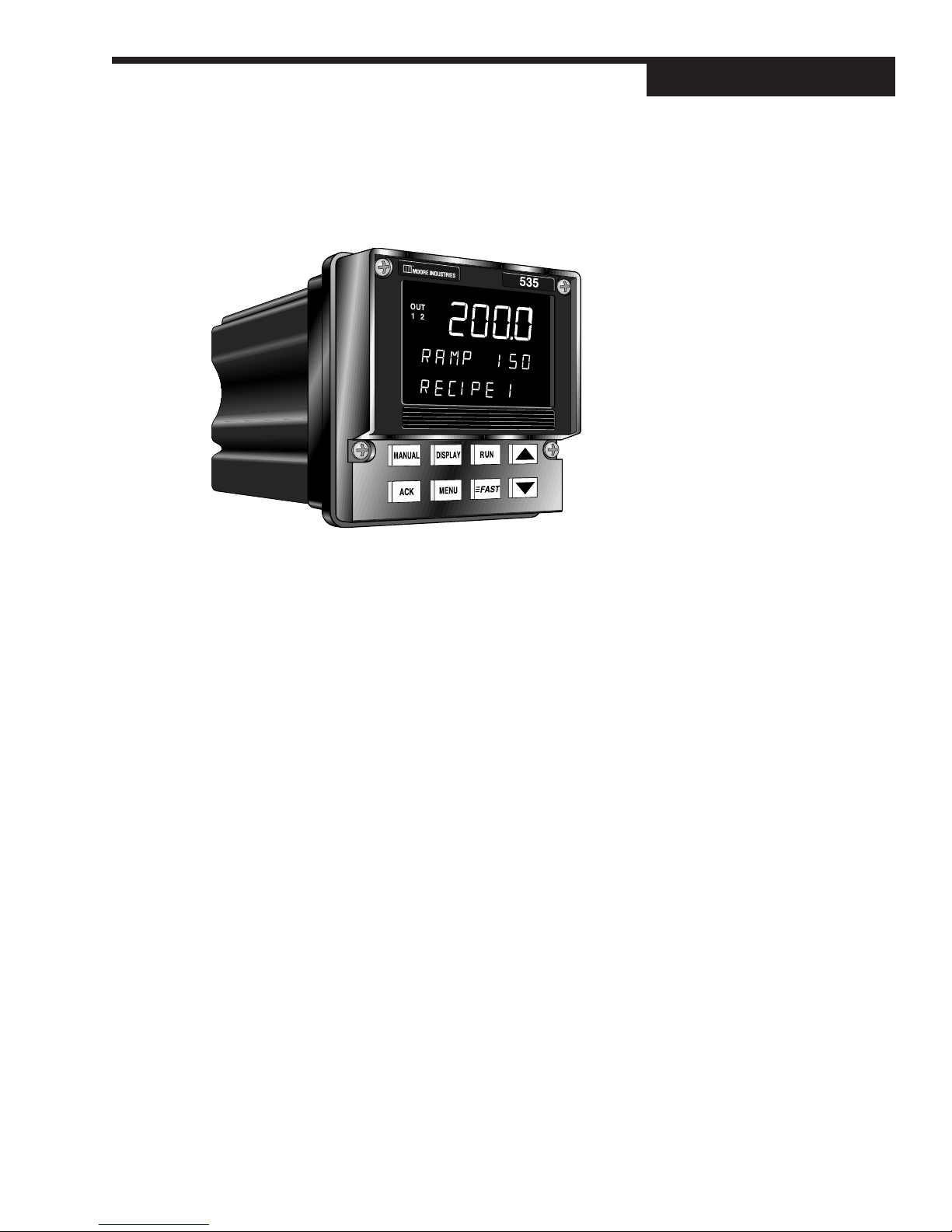
From its surge-resistant power supply to its rugged construction, the 535 Profile
Controller is designed to ensure the integrity of your process with maximum reliability — hour after hour, day after day. The isolated inputs and outputs guard
against the dangers of electrical interference, the front face meets NEMA 4X standards for watertight operation and exposure to corrosive environments, and the
solid metal housing and sturdy rubber keys enhance durability and ESD protection.
The 535 Profile Controller has been engineered to be the industry’s most user–
friendly process controller. With three digital display areas — two offering up to 9
characters of true alphanumerics — the controller effectively eliminates the cryptic
messages that could confuse even the most experienced operator. The bright,
crisp display is vacuum fluorescent, and offers much better readability than any
other display technology. Additional operator–friendly features include: custom
programmable alarm messages, illuminated keys, and an easy–to–use menu
system.
The 535 Profile Controller is the most accurate instrument in its class. With a sampling rate of ten times per second, it is ideal for demanding pressure and flow applications. The controller also offers a universal process input and modular, field
interchangeable outputs that allow more flexibility than ever before. The RS-485
serial communications interface allows the controller to utilize sophisticated software routines and high speed hardware to provide exceptionally fast and accurate transmission of data. The 535 Profile Controller also offers sophisticated
control algorithms, including exclusive Adaptive Tune which constantly analyzes
your process and makes modifications to the tuning parameters to ensure you’re
always under control.
Thank you for selecting the 535 Profile
Controller — the most sophisticated
instrument in its class. It will provide
you with years of reliable, trouble-free
performance.
535 PROFILE CONTROLLER MODES
There are four operating modes for the 535 profile controller:
OPERATION, the default mode of the controller. When the 535-PROF is oper-
ating, you can run recipes, change setpoints, select manual control and change
output level, acknowledge alarms and monitor conditions.
535-PROF User’s Manual Chapter 1 1
Page 11

Introduction
SET UP, also referred to as configuration. Here the basic functions of the instru-
ment are configured, such as input and output assignments, alarm types and
special functions.
TUNING, where control function parameters for Proportional, Integral and Derivation (PID) are configured. Use this mode periodically to optimize the control
performance of the instrument.
RECIPE SET UP, where the ramps, dwells and events for each recipe are configured.
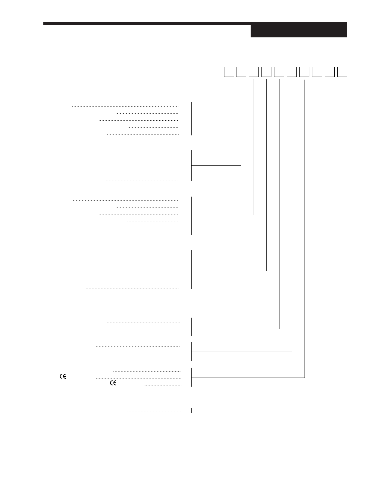
ORDER CODE, PACKAGING INFORMATION
Compare the product number to the ordering code on page 3 to determine the
outputs and options installed on the controller. The product number is printed on
the label on the top of the controller case.
Included with this 535 Profile Controller are:
• a 535 Profile Controller User’s Manual
• mounting hardware
• 1 sheet of Engineering unit adhesive labels
WHERE TO GO NEXT
• To become familiar with the controller interface, continue to Chapter 2.
• For important hardware installation guidelines, see Chapters 3 and 4.
• For a detailed description of all the software menus and parameters,
follow through Chapters 5 and 6. Appendix 1 can be used as a basic guideline to these parameters.
TEXT FORMATTING IN THIS MANUAL
Feature Format
KEYS RUN DISPLAY
or
RUN DISPLAY
ICONS OUT, ALM
MENUS CONFIG., TUNING,
PARAMETERS CYCLE TM:1, MIN.OUT2
PARAMETER VALUES OFF, SETPOINT, LAST OUT.
DISPLAY MESSAGES TOO HOT, OUT%
2 Chapter 1 535-PROF User’s Manual
Page 12
Order
Output 1: Control Code
None 0
Mechanical Relay (5 amp) 1
Analog (milliamp) 2
Solid State Relay (triac) (1 amp) 3
DC Logic (SSR drive) 4
Output 2: Control, Alarm, or Retransmission
None 0
Mechanical Relay (5 amp) 1
Analog (milliamp) 2
Solid State Relay (triac) (1 amp) 3
DC Logic (SSR drive) 4
Output 3: Control, Alarm, Retransmission, or Loop Power
None 0
Mechanical Relay (5 amp) 1
Analog (milliamp) 2
Solid State Relay (triac) (1 amp) 3
DC Logic (SSR drive) 4
Loop Power 5
Introduction
535 – 00
Output 4: Alarm, Retransmission, or Loop Power
None 0
Mechanical Relay (0.5 amp, 24 V) 1
Analog (milliamp) 2
Solid State Relay (triac) (0.5 amp, 24 V) 3
DC Logic (SSR drive) 4
Loop Power 5
Options
Enter “0” if not desired
Slidewire Feedback for Position
Proportioning Output A
24 VAC/24 VDC Operation F
Slidewire and 24 VAC/24 VDC G
Remote Setpoint B
Profile Controller Option C
Remote Setpoint and Profile E
Set of Five Digital Inputs D
Certification H
Five Digital Inputs and Certification J
Serial Communications
Enter “0” if not desired
RS-485 Serial Communications S
Note 1: Capability for position proportioning output is specified by ordering 535-11xxAxxx00, 535-33xxAxxx00, or 535-44xxAxxx00. Note 2: Capability for
velocity proportioning output is specified by ordering 535-11xxxxxx00, 535-33xxxxxx00, or 535-44xxxxxx00.
alarms.
when used as the fourth output.
535-PROF User’s Manual Chapter 1 3
Note 4: All outputs are interchangeable modules. Note 5: The mechanical relay and solid state relay modules are derated to 0.5 amp at 24 Vac
Note 3: Up to two outputs may be used for
Page 13
Operation
y
CHAPTER 2
BASIC INTERFACE
Icons
OUT
1 2
ALM
1 2
535
Displays:
1st
2nd
3rd
Location for
MANUAL DISPLAY RUN
identification
label
ACK MENU FAST
s
Ke
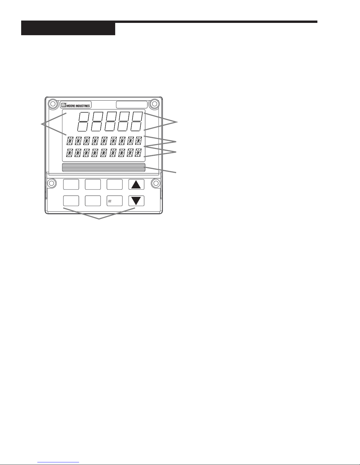
DISPLAYS
The display strategy of the 535 Profile Controller is the same for all modes.
1st Display (five 7-segment digits)
• For the process variable value.
2nd Display (nine 14-segment digits)
• For the setpoint, deviation, output level or valve position (if available)
• In RECIPE SET UP, TUNING or SET UP mode, for the parameter name.
• Upon power up, indicates the current setpoint.
• In OPERATION Mode, displays program operating values:
a. The target soak setpoint value for this segment, for example:
SP 1425 means “the final [soak] setpoint during this segment is 1425”
b. The current setpoint value, for example:
RAMP 300 means “the current ramping setpoint value is 300”
SOAK 1425 means “the current soak segment setpoint value is 1425”
3rd Display (nine 14-segment digits)
• For alarm messages, loop name, errors, etc.
• In RECIPE SET UP, TUNING or SET UP mode, the value or choice of
parameter shown in the 2nd display.
• In OPERATION Mode, displays recipe status values and messages. It
will alternate every two seconds between the selected recipe status value
and the next message ( if any messages are active).
a. The ramp or soak segment number being run or held, for example:
RAMP 10/11 means “using ramp segment 10 of 11 segments in this
recipe”
SOAK 3/4 means “using soak segment 3 of 4 segments in this recipe”
Figure 2.1
Operator Interface
4 Chapter 2, Controller Operation 535 User's Manual
Page 14

Operation
b. The amount of time left in the current ramp or soak segment or the amount
of time the soak segment has been waiting to run or continue due to
guaranteed soak, for example:
15:03 LEFT means “15:03 is remaining in this segment’s current cycle”
WAIT 12:37 means “the soak segment has been waiting for 12:37”
c. The status of events will be displayed. Active events will be indicated
by a ‘1’ and inactive events by a ‘0’, for example:
EVENT 000 means “events 1, 2, and 3 are inactive”
EVENT 100 means “event 1 is active and events 2 and 3 are inactive”
EVENT 111 means “events 1, 2, and 3 are active”
d. The current cycle number and the total number of cycles will be dis-
played, for example:
CYCLE 1/1 means “the first and only cycle is currently active”
CYCLE 13/99 means “the thirteenth of 99 cycles is currently active”
CYCLE 246 means “the 246th cycle [in continual cycling] is currently
active”
e. The current recipe number will be displayed, for example:
RECIPE 6 means “the sixth recipe is currently active”
FAST
MANUAL
RUN
ICONS (LIT)
OUT Indicates either the relay output is energized, or the analog output is
greater than 0%.
ALM1 Indicates the respective alarm (one) is active.
ALM2 Indicates the respective alarm (two) is active.
ALM Indicates an alarm wihtout an assigned output is active.
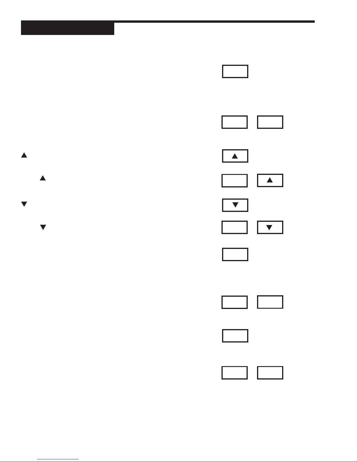
KEYS
FAST
No independent function. Press to modify the function of another key.
MANUAL
Press to toggle between manual and automatic control.
When lit, indicates the unit is under manual control.
Press to abort a running or held recipe and return controller to manual control.
RUN (For Profile Control)
Press to Run, Hold or Abort a recipe.
When a recipe is active, press to prompt a display message for selecting the
recipe nuumber (1 through 20).
When lit, indicates a recipe is running.
When blinking, indicates a recipe is on hold.
FAST
535 User's Manual Chapter 2, Controller Operation 5
RUN
+
FAST+RUN
When a recipe is running or held, press to advance to next segment.
Page 15
Operation
DISPLAY
Press to toggle through values in the 2nd display for setpoint, ramping setpoint
(if available), deviation, PV1 (If PV source is not PV1), PV2 (if PV Source is not
PV1), output and valve position (if available).
In RECIPE SET UP, TUNING, SET UP mode, press to return controller to
OPERATION mode (display will show current setpoint).
FAST+DISPLAY
When a recipe is running or held, press to select recipe status.
When no recipe is running or held, press to display EVENT 000 message.
Press to increase the value or selection of displayed parameter.
FAST+
Press to scroll through values at a faster rate.
Press to decrease the value or selection of displayed parameter.
FAST+
Press to scroll through values at a faster rate.
DISPLAY
FAST
FAST
FAST
+
+
+
DISPLAY
ACK
Press to acknowledge (an) alarm(s).
Press to acknowledge Run, Abort and next segment commands.
When lit, indicates there is an acknowledgeable alarm or an event is being held
at the end of a recipe.
FAST+ACK
For events held at the end of a recipe, press to acknowledge and disable the
events.
MENU
In OPERATION mode, press to access the TUNING mode/menu.
In RECIPE SET UP, SET UP or TUNING mode, press to advance through a
menu’s parameters. (Use FAST+MENU to advance to to the next menu.)
FAST+MENU
In Automatic control, press to enter RECIPE SET UP mode. In Manual control,
press to enter the SET UP mode.
In SET UP mode, press to advance through menus. (Use MENU by itself to
access the parameters of a particular menu.)
ACK
FAST
MENU
ACK
+
MENUFAST
+
6 Chapter 2, Controller Operation 535 User's Manual
Page 16

Operation
BASIC PROFILE CONTROLLER OPERATING
PROCEDURES
Use the following as a quick guide to key operating functions of the 535-PROF.
To Enter the RECIPE SET UP Mode
1. To enter the RECIPE SET UP mode from any other mode, hold down FAST
and press MENU. The MENU key will illuminate. The 2nd display line will
indicate RECIPE #, where # represents the recipe number.
2. Use the or key to select the recipe number.
3. Press MENU by itself. The first parameter of this menu for this recipe will
appear in the 2nd display, replacing RECIPE # , while the choices or selections appear in the 3rd display.
4. Pressing DISPLAY at any time exits the RECIPE SET UP mode and returns you to OPERATION mode.
To Enter the SET UP Mode
1. If you are not in MANUAL control, press MANUAL. The MANUAL key will
illuminate.
2. Hold down FAST and press MENU. The MENU key will illuminate.
RECIPE # will appear alone in the 2nd display. Entering the SET UP mode
first gives you access to the RECIPE SET UP mode.
3. Hold down FAST and press MENU. CONFIG appears alone in the 2nd display. You are now in the SET UP mode. See Chapter 5 for a list of all Set Up
parameters, and Chapter 7 for applications.
To run a recipe:
1. Pressing the RUN key prompts the choice of recipe number.
2. Use the or key to select the proper recipe.
3. Press the ACK key to start the recipe.
To hold a recipe:
1. While a recipe is running (indicated when the RUN key is lit red), briefly press
the RUN key. The key will blink on and off and the 3rd display will indicate
HOLDING.
2. Press the RUN key again to resume the recipe.
To abort a recipe and place the controller in MANUAL
mode:
1. While a recipe is running (indicated when the RUN key is lit red), press the
MANUAL key. The 2nd display line will show REC. ABORT and the 3rd display will show PRESS ACK.
2. Press the ACK key within 5 seconds to abort the recipe and place the controller in MANUAL mode. The manual output value will be the last output at
the point the recipe was aborted. The raise and lower keys may be used to
modify the output.
To abort a recipe and control to the IDLE setpoint:
1. While a recipe is running (indicated when the RUN key is lit red), press the
RUN key and hold until the 2nd display line shows REC. ABORT and the 3rd
display will show PRESS ACK.
2. Press the ACK key within 5 seconds to abort the recipe and the controller
535 User's Manual Chapter 2, Controller Operation 7
Page 17

Operation
will control to the IDLE setpoint. The raise and lower keys may be used to
adjust the setpoint.
To display the setpoint (SP), ramping setpoint (RAMP),
deviation (DEV) or output % (OUT %) while a recipe is running:
1. Toggle the DISPLAY key until the appropriate selection appears on the 2nd
display line.
To display the recipe number, the current ramp or soak
segment, the time left in the segment, the event status or
the number of recipe cycles completed:
1. Press the FAST key and toggle the DISPLAY key until the appropriate se-
lection appears on the 3rd display line.
BASIC PROCESS CONTROLLER OPERATING
PROCEDURES
This is a guide to controller operation when not using the profile options.
To select /change a setpoint
1. Press the MENU key twice to display SP SELECT in the TUNING mode.
2. Use the or key to toggle the active setpoint.
Before the newly selected setpoint is made active, there is two-second de-
lay to prevent any disruptive bumps.If the setpoint displayed is ramping,
RAMPING will show the 3rd display.
3. To change the setpoint value, press or while the setpoint is shown in
the 2nd display.
To change from auto to manual control (bumpless transfer)
1. When in automatic control, press the MANUAL key at any time, except while
in the TUNING mode.
2. The MANUAL key will light in red, and the 2nd display will immediately change
to indicate current output level.
To change from manual to auto
1. When in manual control, press MANUAL at any time except while in the SET
UP mode.
2. The 2nd display will not change, and the MANUAL key will no longer be lit
once control changes.
To change manual output values
1. Make sure the controller is under manual control.
2. Use the DISPLAY key to toggle 2nd display to output level.
3. Use the or key to change the value.
To override security
If a locked operation is attmpted, SECURITY appears in the 2nd display for two
seconds).
1. Use the and keys to quickly enter the security code, which will show
in the 3rd display. The starting value is 0.
Note: Two seconds of key inactivity will clear the display.
8 Chapter 2, Controller Operation 535 User's Manual
Page 18
Operation
535
MANUAL DISPLAY RUN
ACK MENU FAST
OUT
1
ALM
1
BEFORE
AFTER
535
MANUAL DISPLAY RUN
ACK MENU FAST
OUT
1
2. If the code is correct, CORRECT appears in the 3rd display. The display
will clear after two seconds, allowing full access.
4. If code is incorrect, INCORRECT appears in the 3rd display. This will disappear after two seconds, and a new security code can then be entered.
5. The controller will revert back to full security lock after one minute of key
inactivity.
To display control output value
1. Toggle DISPLAY key until the 2nd display shows OUT followed by the output
percentage. This value is the PID output.
• In duplex applications, this value does not directly refer to the output
signal (refer to the Chapter 7 section on Duplex Control for details.)
• For on/off outputs, the output value shown is either ON or OFF.
• For duplex applications with two on/off outputs, the OUT tag is not shown.
In this case, the status of both outputs is shown in the following manner: 1:ON 2:OFF (1 and 2 are the respective outputs).
To display the active PID set
1. Press MENU to reach Tuning Mode.
2. In TUNING Mode, press MENU to reach the correct Menu parameter.
3. The active PID set will have an asterisk (*) on both sides of the value.
ALARM OPERATION
Alarms may be used in systems to provide warnings of unsafe conditions. All
535 operators must know how the alarms are configured, the consequences of
acknowledging an alarm and how to react to alarm conditions.
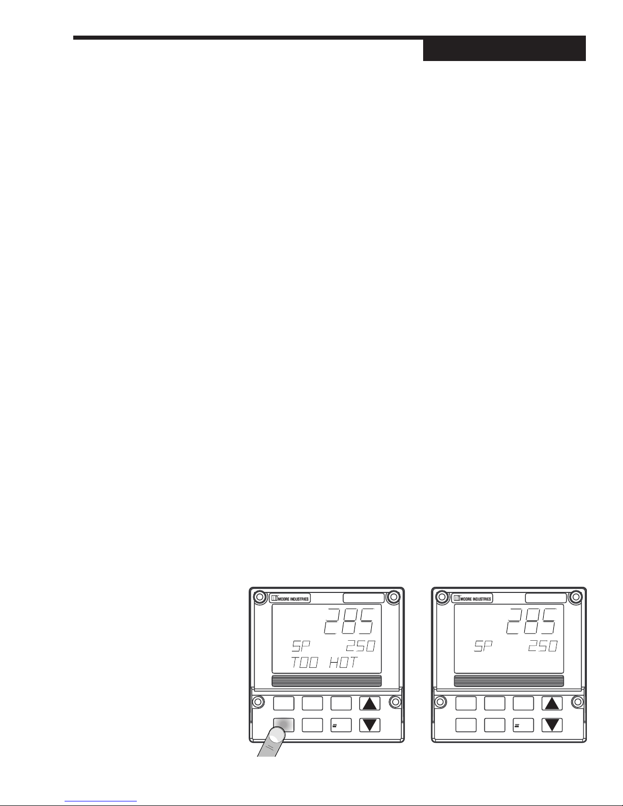
Alarm Indication
• lit icons ALM 1 and/or ALM 2
• lit ACK key
• displayed alarm message
Acknowledgable alarms meet the first two of these conditions.
Non-acknowledgable alarms only meet the first condition (only icon is lit).
Figure 2.2
Before and After Acknowledging
an Alarm
535 User's Manual Chapter 2, Controller Operation 9
Page 19

Operation
To acknowledge an alarm(s):
1. To acknowledge Alarm 1, press ACK once.
2. To acknowledge Alarm 2, press ACK twice.
3. If both alarms are activated, press ACK once to acknowledge Alarm 1, then
again to acknowledge Alarm 2.
4. The message and alarm icon dissappear. Refer to
Figure 2.2
.
Latching Alarms
If an alarm is set up to be latching (for details, see Chapter 5) then, in general,
it must be acknowledged in order to clear the alarm and release the relay (if
applicable). A non-latching alarm will clear itself as soon as the process leaves
the alarm condition.
Limit Sequence
An alarm can be configured to be both latching and non-acknowledgeable. In
this case, the alarm is acknowledgeable only after the process has left the alarm
condition. This is similar to the function of a limit controller.
More on Alarms
For more details on how to set up alarms and for examples of various ways alarms
can be set up, refer to the section on Alarms in Chapter 7.
NOTE:
All alarms are software alarms unless
tied to an output relay in the SET UP
mode. See Chapters 5 and 7 for
details on alarms.
NOTE:
Powering down the 535
acknowledges/clears all latched
alarms. When powering up, all alarms
will be reinitialized.
10 Chapter 2, Controller Operation 535 User's Manual
Page 20
CHAPTER 3
INSTALLATION
MOUNTING THE CONTROLLER
The 535-PROF front face is NEMA 4X rated (waterproof). To obtain a waterproof
seal between the controller and the panel, follow these directions:
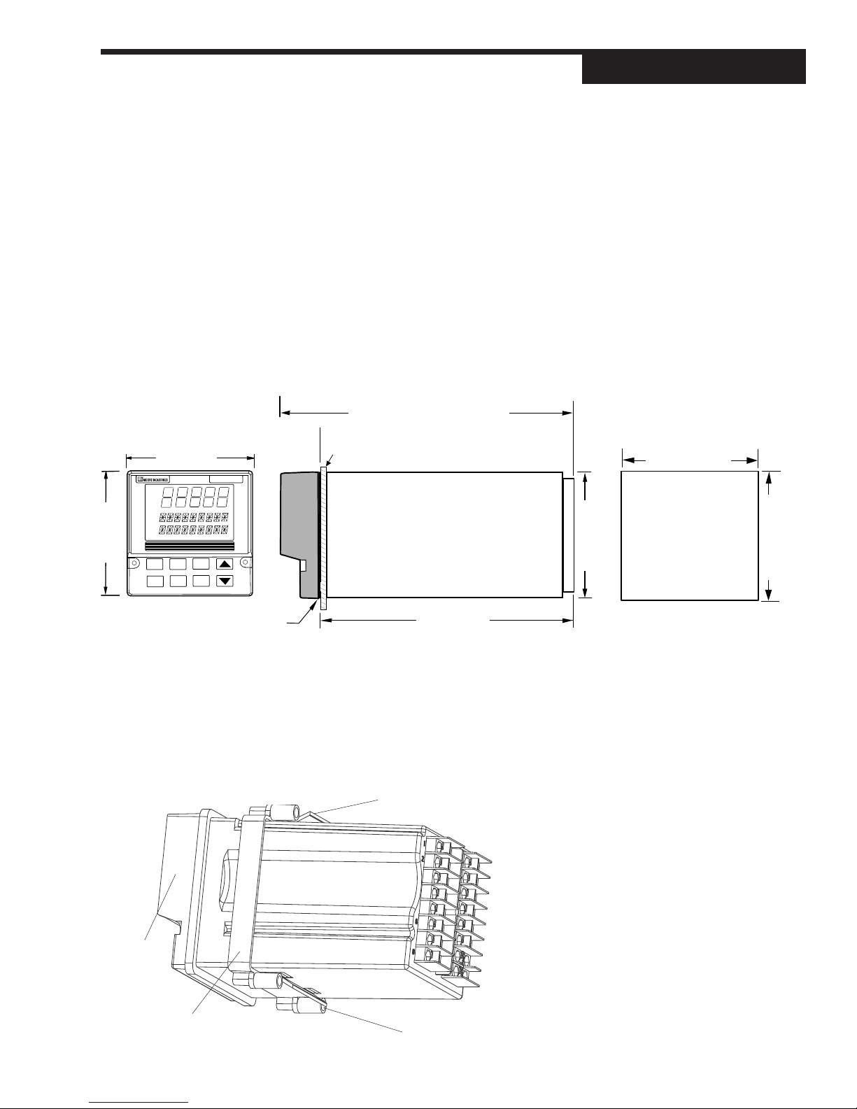
1. The 535-PROF fits in a standard 1/4 DIN cutout. Mount the 535-PROF in
any panel with a thickness from .06 in. to .275 in. (1.5 mm to 7.0 mm).
2.
Figure 3.1
be precise, and the edges free from burrs and waves.
shows the controller and panel dimensions. The panel cutout must
7.180 (182.37) OVERALL LENGTH
1.180 (29.97)
3.770 (95.76)
OUT
1 2
ALM
1 2
5 3 5
PANEL
Install / Wire
Figure 3.1
Instrument Panel & Cutout Dimensions
3.622 (92.00) MIN.
3.653 (92.80) MAX.
3.622 (92.00) MIN.
3.653 (92.80) MAX.
3.770 (95.76)
6.000 (152.40)
SIDE
FRONT
BEZEL
GASKET
3. Place bezel gasket around the controller case (starting at the back of controller). Then, slide the gasket against the back of the bezel.
4. With the bezel gasket in place, insert the 535-PROF into the panel cutout
from the front of the panel.
5. Slide the mounting collar over the back of the case, as shown in
Figure 3.2.
The collar clip edges will lock with matching edges on the controller case.
6. Insert the four mounting collar screws from the rear of the collar. Gradually
Mounting Clip
Bezel
3.585 (91.06)
CUTOUT
Figure 3.2
Attaching mounting collar
Mounting Collar
535-PROF User's Manual Chapter 3 11
Collar Screws (1 of 4)
Page 21
Install / Wire
AUTION!
C
The enclosure into which the 535PROF Controller is mounted must be
grounded.
WARNING!
Avoid electrical shock. Do not connect
AC power wiring at the source
distribution panel until all wiring
connections are complete.
tighten the screws (using a Phillips #2 screwdriver) to secure the controller
against the panel.
7. If there is difficulty with any of the mounting requirements, apply a bead of
caulk or silicone sealant behind the panel around the perimeter of the case
WIRING
535-PROF controllers are thoroughly tested, calibrated and “burned in” at the
factory, so the controller is ready to install. Before beginning, read this chapter
thoroughly and take great care in planning a system. A properly designed system
can help prevent problems such as electrical noise disturbances and dangerous
extreme conditions.
1. For improved electrical noise immunity, install the 535-PROF as far away
as possible from motors, relays and other similar noise generators.
2. Do not run low power (sensor input) lines in the same bundle as AC power
lines. Grouping these lines in the same bundle can create electrical noise
interference.
3. All wiring and fusing should conform to the National Electric Code and to
any locally applicable codes.
4. An excellent resource about good wiring practices is the IEEE Standard No.
518-1982 and is available from IEEE, Inc., 345 East 47th Street, New York,
NY 10017, (212) 705-7900.
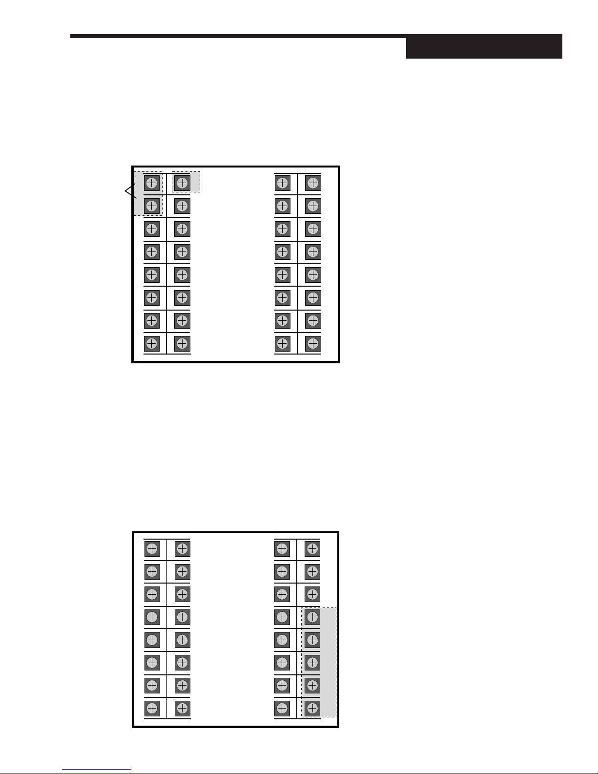
Diagrams on the next three pages serve as guides for wiring different types of
process inputs. The shaded areas on the diagrams show which rear terminals
are used for that type of wiring.
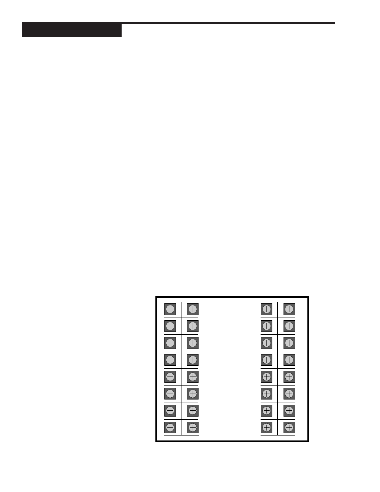
Figure 3.3
All 535-PROF Terminal Assignments
Actual 535-PROF device only has top
and bottom numbers of each column of
terminals marked.
WARNING!
ELECTRIC SHOCK HAZARD!
Terminals 1 and 2 carry live power. DO
NOT touch these terminals when
power is on.
WARNING!
Terminal 9 must be grounded to avoid
potential shock hazard, and improved
noise immunity to your system.
LINE
NEUTRAL
OUT 1–
OUT 1+
OUT 2–
OUT 2+
OUT 3–
OUT 3+
TOP (as viewed from back of controller)
1
2
3
4
5
6
7
816
EARTH
917
GND
S/W 1
10
S/W 2
11
S/W 3
12
RSP–
13
RSP+
14
OUT 4–
15
OUT 4+
DIN
GND
DIN 1
DIN 2
DIN 3
DIN 4
DIN 5
COLD
JUNC–
COLD
JUNC+
25
18
19
20
21
22
23
26
27
28
29
30
31
24 32
not
used
COMM–
COMM+
PV2–
PV2+
RTD 3RD
PV1–
PV1+
12 Chapter 3 535-PROF User's Manual
Page 22
AC Power Input
Terminals 1 and 2 are for power. Terminal 9 is the earth ground.
Use a 0.5 Amp, 250 V, fast-acting fuse in line with your AC power connection.
TOP
Install / Wire
EARTH/
917
GROUND
10
11
12
13
14
15
18
19
20
21
22
23
25
26
27
28
29
30
31
24 32
POWER
1
2
3
4
5
6
7
816
Screws must be tight to ensure good electrical connection
Process Variable Input
The 535-PROF accommodates the following types of process variable inputs:
• Thermocouple Input
• RTD Input
• Voltage Input
• Milliamp Input with External Power Supply
• Milliamp Input with Internal Power Supply
Each type of input can be wired for PV1 (terminals 31 and 32) or for PV2
(terminals 28 and 29).
Figure 3.4
AC Power Input Terminals
CAUTION!
Do not run low power (sensor input)
lines in the same bundle as AC power
lines. Grouping these lines in the
same bundle can create electrical
noise interference.
1
2
3
4
5
6
7
917
10
11
12
13
14
15
816
535-PROF User's Manual Chapter 3 13
25
18
19
20
21
22
23
26
27
28
29
30
31
24 32
Figure 3.5
Process Variable Terminals
PV 2-
PV2+
RTD 3rd
PV 1-
PV1 +
Page 23
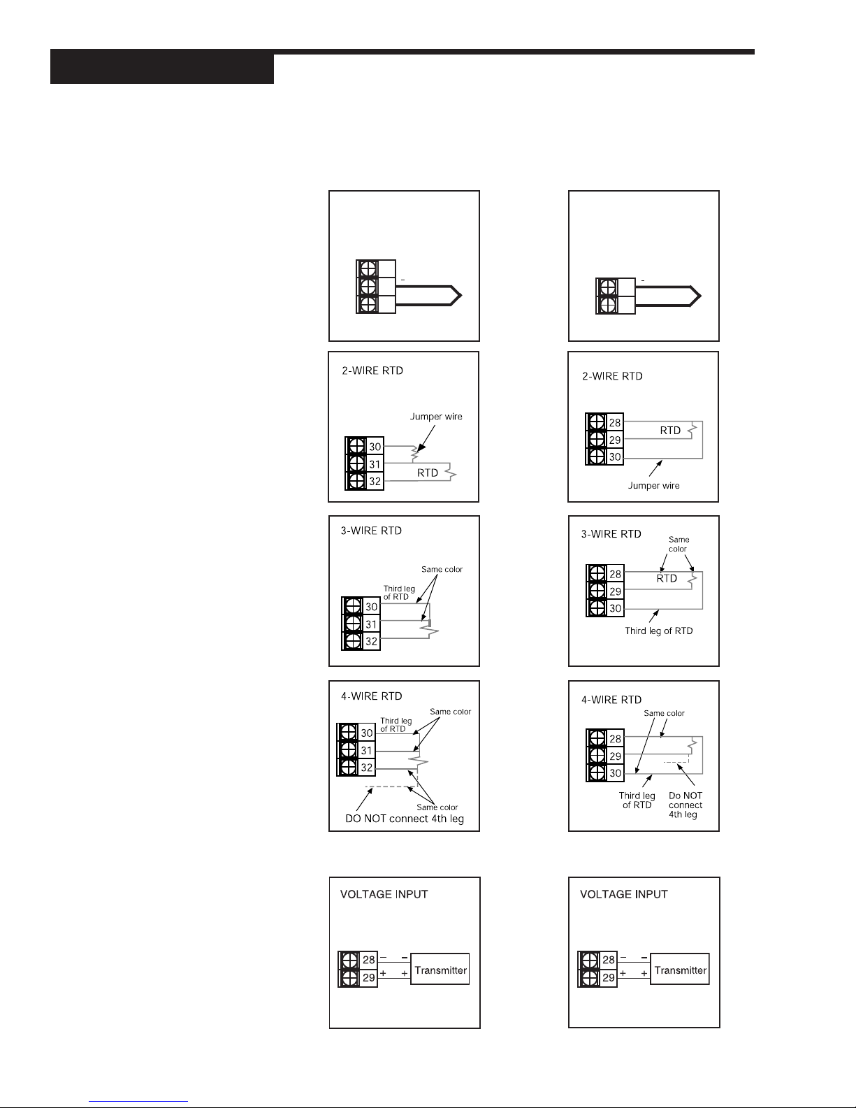
Install / Wire
NOTE:
Typically, in the U.S., negative leads
are red.
Figure 3.6
PV1 and PV2 Wiring for Milliamp, RTD
and Voltage Inputs.
For PV1
THERMOCOUPLE INPUT
30
31
+
32
For PV2
THERMOCOUPLE INPUT
28
+
29
14 Chapter 3 535-PROF User's Manual
Page 24
Install / Wire
For PV1
MILLIAMP INPUT
2-wire transmitter with
separate power supply
– External +
Power Supply
31
32
– Transmitter +
MILLIAMP INPUT
2-wire transmitter with
loop power supply
-
-
+
-
+
+
-
+
2-wire
transmitter
+
Input power
for transmitter
+
4-20 mA output
-
from transmitter
+
15
16
31
32
MILLIAMP INPUT
4-wire transmitter with
loop power supply
15
16
31
32
For PV2
MILLIAMP INPUT
2-wire transmitter with
separate power supply
External +
Power Supply
28
29
Transmitter +
MILLIAMP INPUT
2-wire transmitter with
loop power supply
—
—
15
16
28
29
MILLIAMP INPUT
4-wire transmitter with
loop power supply
15
16
28
29
—
+
—
+
+
—
+
2-wire
transmitter
+
—
Input power
for transmitter
+
4-20 mA output
—
from transmitter
+
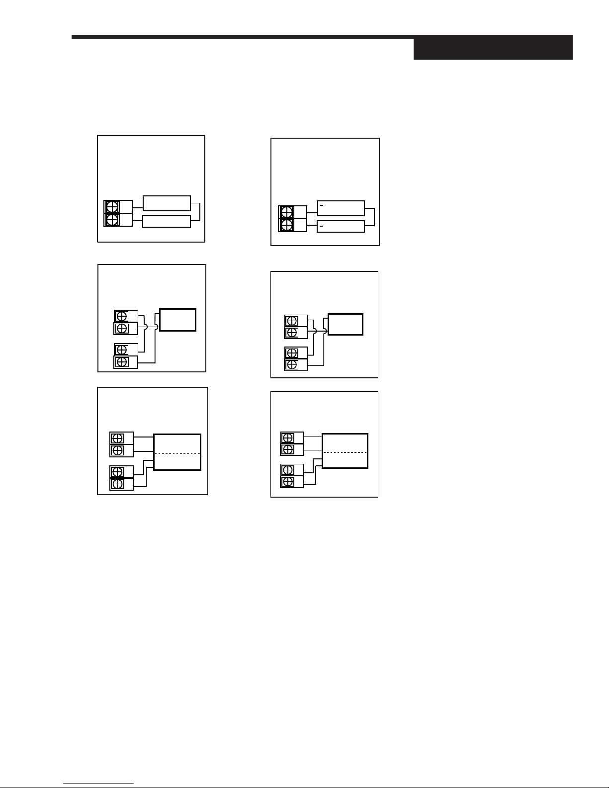
Figure 3.7
PV1 and PV2 Wiring for Milliamp
Inputs with Internal and External
Power Supply
NOTE:
To use loop power, there must be a
loop power module is installed in the
3rd or 4th output socket. Compare the
controller product number with the
order code in Chapter 1 to determine
if the 535-PROF has a loop power
module installed. To install a loop
power module, refer to Chapter 4
.
535-PROF User's Manual Chapter 3 15
Page 25
Install / Wire
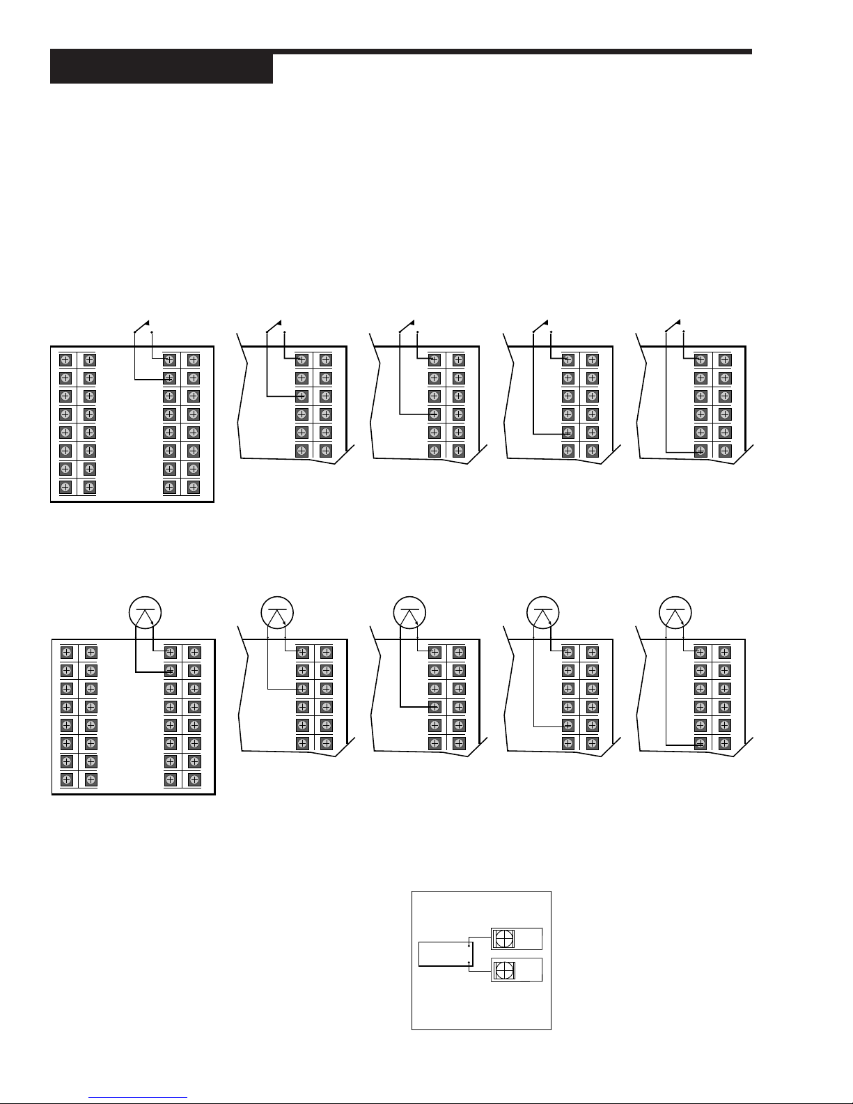
Figure 3.8
Digital inputs Wiring with a Switch
or Relay
Digital Input(s)
Digital inputs can be activated in three ways: a switch (signal type), closure of
a relay, or an open collector transistor. Digital inputs are only functional when
that option is installed (via hardware) The controller detects the hardware and
supplies the appropriate software menu.
1. Digital Inputs with a switch or relay
Wire the switch/relay between terminal 17 and the specific digital input
terminal (
Figure 3.8
).
1
2
3
4
5
6
7
8
Screws must be tight to ensure electrical connection
DIN
GND
DIN 1
DIN 2
DIN 3
DIN 4
DIN 5
17
18
19
20
21
22
23
24 32
9
10
11
12
13
14
15
16
25
26
27
28
29
30
31
Figure 3.9
Digital Input Wiring with an Open
Collector
1
2
3
4
5
6
7
8
Screws must be tight to ensure electrical connection
DIN
GND
DIN 1
DIN 2
DIN 3
DIN 4
DIN 5
17
18
19
20
21
22
23
24 32
9
10
11
12
13
14
15
16
25
26
27
28
29
30
31
DIN
GND
DIN 1
DIN 2
DIN 3
DIN 4
DIN 5
17
18
19
20
21
22 30
25
26
27
28
29
DIN 1
DIN 2
DIN 3
DIN 4
DIN 5
GND
DIN
17
18
19
20
21
22 30
2. Digital Inputs with an Open Collector
An open collector is also called a transistor. Wire the transistor between
terminal 17 and the specified digital input terminal (
GND
DIN 1
DIN 2
DIN 3
DIN 4
DIN 5
DIN
17
18
19
20
21
22 30
25
26
27
28
29
GND
DIN 1
DIN 2
DIN 3
DIN 4
DIN 5
DIN
17
18
19
20
21
22 30
Remote Setpoint Option
25
26
27
28
29
25
26
27
28
29
GND
DIN 1
DIN 2
DIN 3
DIN 4
DIN 5
GND
DIN 1
DIN 2
DIN 3
DIN 4
DIN 5
DIN
DIN
17
18
19
20
21
22 30
17
18
19
20
21
22 30
25
26
27
28
29
25
26
27
28
29
DIN
17
GND
DIN 1
18
DIN 2
19
DIN 3
20
DIN 4
21
DIN 5
22 30
Figure 3.9
DIN
17
GND
DIN 1
18
DIN 2
19
DIN 3
20
DIN 4
21
DIN 5
22 30
25
26
27
28
29
)
25
26
27
28
29
Figure 3.10
Remote Setpoint Terminals
16 Chapter 3 535-PROF User's Manual
Use terminals 13 and 14 to connect the remote setpoint signal
(see
Figure 3.10
).
-
Source
-
+
13
+
14
Page 26
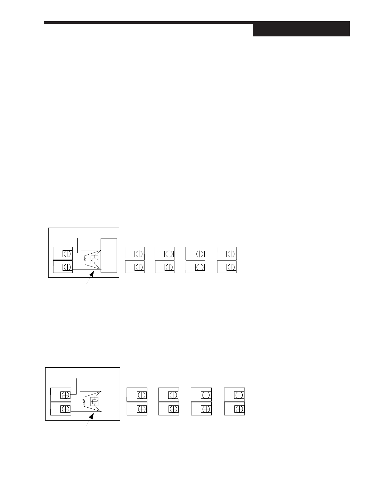
OUTPUT MODULES
The 535-PROF output modules are used for control, alarms and retransmission.
The four output module types are: Mechanical Relay, Solid State Relay (Triac),
DC Logic (SSR Drive) and Analog (Milliamp)
To install these modules, plug them into any of the four output sockets on the
printed circuit boards (refer to Chapter 4). The wiring is the same whether the
modules are used for control, alarm or retransmission.
The diagrams on the next two pages are a guide for properly connecting the
various outputs. To find out which module(s) have been installed in the controller,
compare the product number on the controller label with the section Order Code
in Chapter 1. This section also includes a diagram of how to wire a position
proportioning output, a special application using two mechanical or two solid
state relays.
1. Mechanical Relay Output
• Output 1 is always Control 1.
• Outputs 1, 2 and 3 are jumper selectable for normally open and normally closed on the power supply circuit board.
• Output 4 is always configured for normally open and has reduced
voltage and current ratings (see Specifications).
Install / Wire
NOTE:
Refer to
corresponding jumpers.
Second input jumper connector on the
option board must be in either
(milliamp) or V (voltage) position.
Figure 4.2
for location of the
mA
Line Power
3
Load
4
Recommend use of both MOV and snubber
Terminals used
with Output
Module 1
3
4
Terminals used
with Output
Module 2
5
6
Terminals used
with Output
Module 3
7
8
2. Solid State Relay (Triac) Output
• Output 1 is always Control 1.
• Respective jumper J1, J2 or J3 must be set to normally open for SSR
(Triac) output.
• Output 4 is always configured for normally open and has reduced
voltage and current ratings (see Specifications).
Terminals used
with Output
Module 3
7
8
3
4
Line Power
+
-
Load
+
Terminals used
with Output
Module 1
3
4
Terminals used
with Output
Module 2
5
6
Terminals used
with Output
Module 4
15
16
Terminals used
with Output
Module 4
15
16
Figure 3.11
Mechanical Relay Output wiring
Figure 3.12
SSR Relay Output Wiring
Recommend use of both MOV and snubber
535-PROF User's Manual Chapter 3 17
Page 27
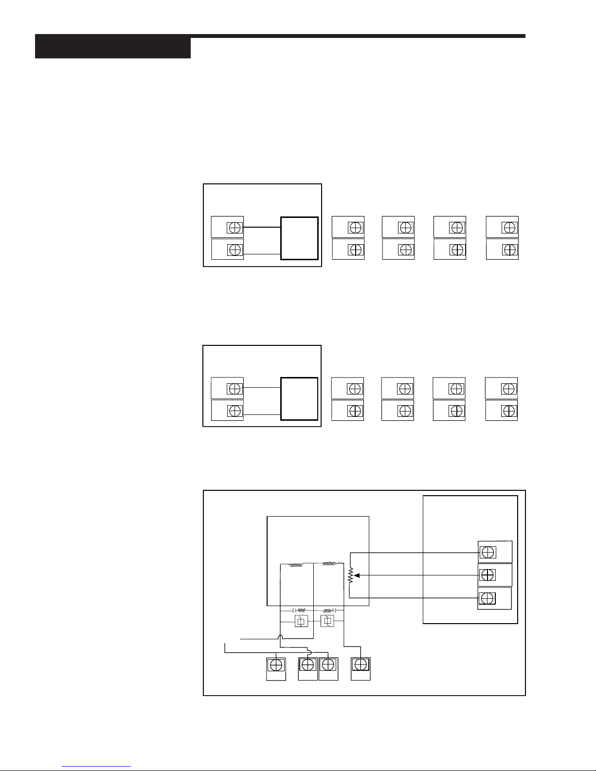
Install / Wire
3. DC Logic (SSR Drive) Output
• Output 1 is always Control 1.
• Respective jumper J1, J2 or J3 must be set to normally open for DC
Logic output.
• Output 4 is always configured for normally open.
Figure 3.13
DC Logic Output Wiring
Figure 3.14
Milliamp Output Wiring
Terminals used
with Output
Module 1
3
_
4
+
_
Load
+
3
4
Terminals used
with Output
Module 2
5
6
Terminals used
with Output
Module 3
7
8
Terminals used
with Output
15
16
4. Milliamp Output
• Output 1 is always Control 1.
• Respective jumper J1, J2 or J3 must be set to normally open for
Milliamp output.
Terminals used
with Output
Module 1
Terminals used
with Output
Module 2
Terminals used
with Output
Module 3
Terminals used
with Output
Module 4
_
3
Load
4
+
3
4
5
6
7
8
15
16
5. Position Proportioning Output
Module 4
(with or without Slidewire Feedback)
POSITION
PROPORTIONING
Electric Motor Actuator
Figure 3.15
Position Proportioning Output Wiring
CCW
Winding
Actuator
Supply
Current
3
COMCWCCW
CW
Winding
4
5
COM
CCW
Slidewire Wiper
0–1050 Ohm
CW
6
18 Chapter 3 535-PROF User's Manual
OUTPUT
10
11
12
Page 28
• Mechanical relay or solid state relay modules must be installed in
output sockets 1 and 2.
• When using velocity control (no slidewire feedback), there are no connections at terminals 10, 11 and 12.
• Use of the slidewire feedback is optional
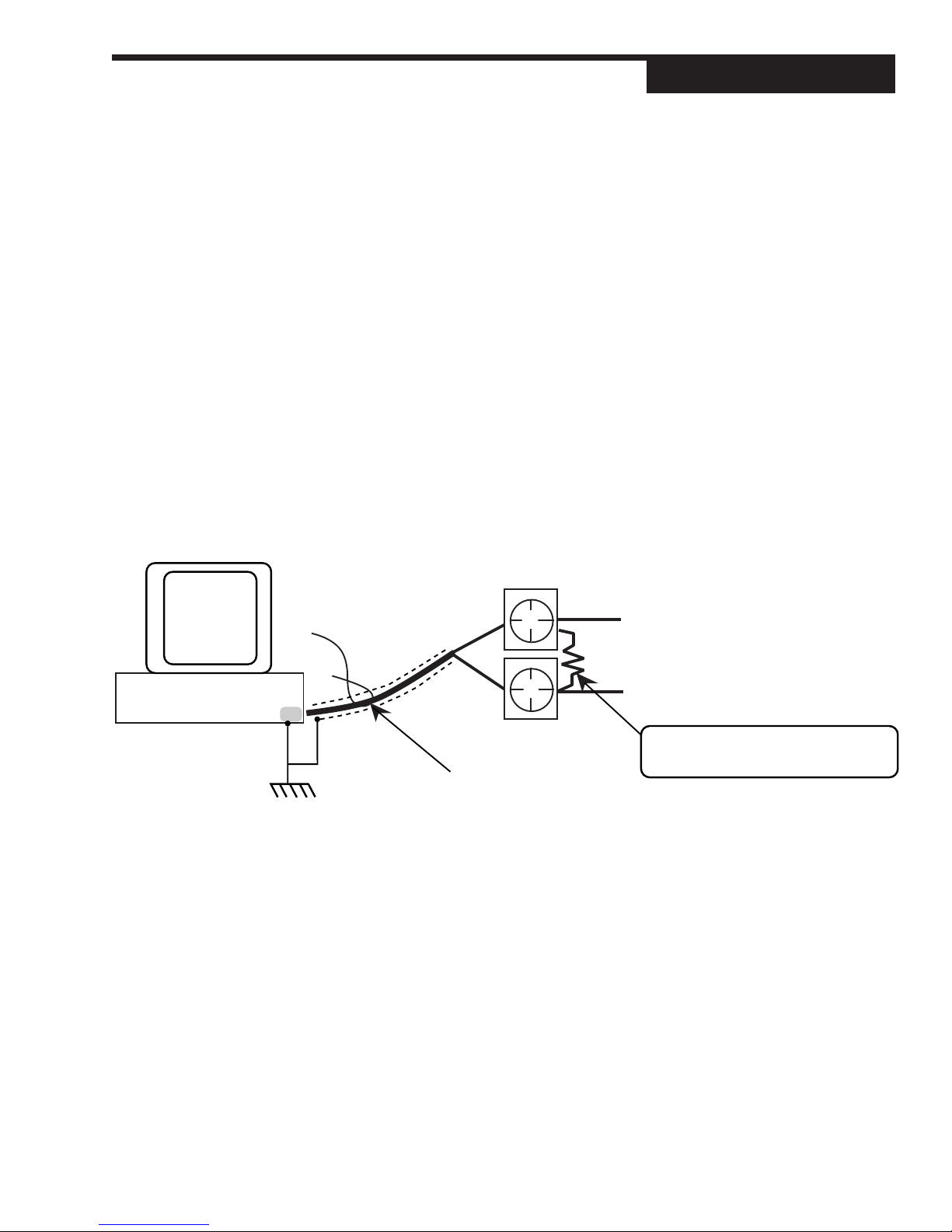
Serial Communications
A twisted shielded pair of wires should be used to interconnect the host and
field units. Belden #9414 foil shield or #8441 braid shield 22-gauge wire are
acceptable for most applications. The foil shielded wire has superior noise
rejection characteristics. The braid shielded wire has more flexibility. The
maximum recommended length of the RS 485 line is 4000 feet. Termination
resistors are required at the host and the last device on the line. Some RS 485
cards/converters already have a terminating resistor. We recommend using
RS-232/RS-485 converter (Product #500-485). The communication protocol is
asynchronous bidirectional half-duplex, hence the leads are labelled
and
Comm –
.
535
Terminals
Comm +
Install / Wire
Figure 3.16
Serial Communications Terminals
PC
or other host
RS-485
Twisted, shielded
port
Comm -
Comm +
CAUTION
The shield needs to be connected continuously
but only tied to one ground at the host.
Failure to follow these proper wiring practices
could result in transmission errors and other
communications problems.
26
27
To "Comm -" terminal of
next Powers device
To "Comm +" terminal of
next device
Use a 60 to 100 Ohm terminating resistor
connected to the two data terminals of
the final Powers device on the line.
535-PROF User's Manual Chapter 3 19
Page 29
Install / Wire
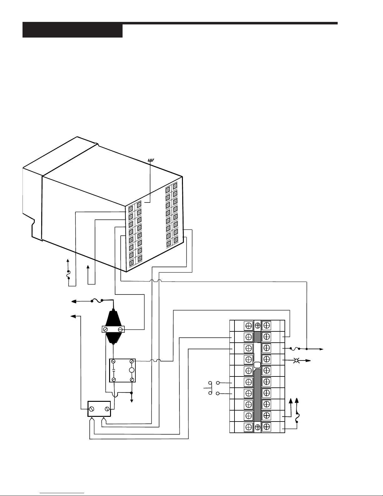
Figure 3.17
535-PROF Wiring with Limit Control
535 PROFILE
CONTROLLER
CONTROLLER
AC POWER
L1
0.5 AMP, 250 V,
FAST ACTING
FUSE
L2
Limit Control
Temperature applications where abnormally high or low temperature conditions
pose potential hazards for damage to equipment, product and operator. For such
applications, we recommend the use of an FM-approved temperature limit
device in conjunction with the process controller. This wiring example illustrates
a typical application using the 535-PROF Process Controller with a 353 Limit
Controller.
EARTH GROUND
25
26
17
27
9
10
1
11
2
12
3
4
5
6
7
8
18
28
19
29
20
21
13
14
15
16
22
23
24
T.C.
30
INPUT
31
32
L1
L2
LOAD
POWER
FAST ACTING
FUSE
HEAT
LOAD
PROCESS SENSOR
LIMIT SENSOR
MERCURY
RELAY
FOR CONTROL
HIGH LIMIT
MECHANICAL
CONTACTOR
COIL
L2
RELAY/
CONTACTOR
COIL POWER
T/C INPUT
N.O.
OPTIONAL
MOMENTARY SWITCH
MANUAL RESET
FOR LIMIT CONTROL
1
+
2
3
-
4
5
6
7
8
9
10
20
19
18
17
16
15
14
13
12
11
353 LIMIT CONTROLLER
FAST
ACTING
FUSE
L2
INDICATOR ON
WHEN LIMIT TRIPS
LIMIT CONTROLLER
AC POWER
L2
L1
FUSE
L1
20 Chapter 3 535-PROF User's Manual
Page 30
CHAPTER 4
HARDWARE SET UP
Hardware configuration determines the available outputs as well as the type of
input signal. The 535-PROF controller comes factory set with the following:
• All specified module and options installed (for details, refer to the Order Code
in Chapter 1).
• Process variable and remote setpoint set to accept a milliamp input
• Relay outputs set to normally open.
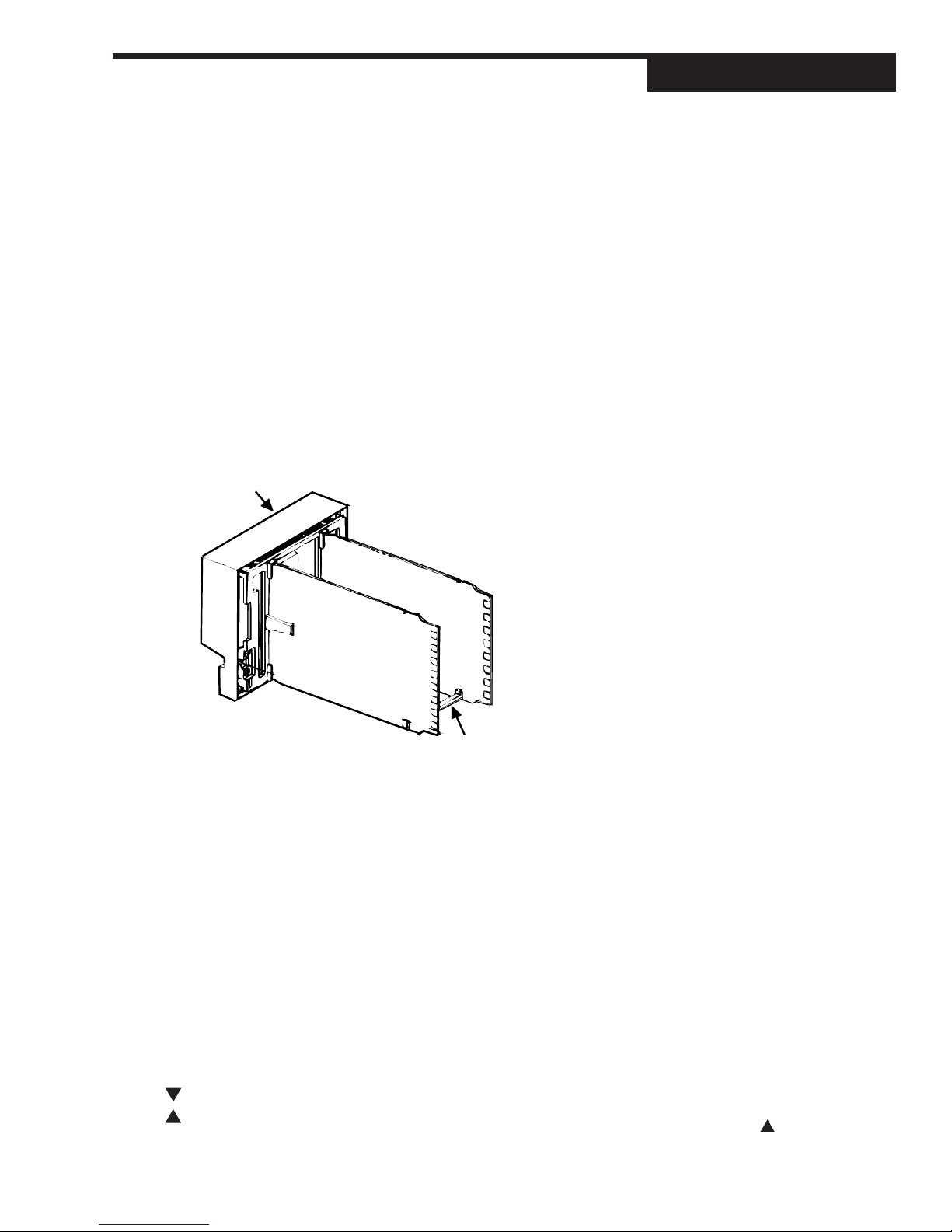
Alter the factory configuration of the 535-PROF, requires accessing the circuit
boards, and locating the jumpers and output modules (see
Figure 4.1
1. With the power off, loosen the four front screws, and remove them.
2. Slide chassis out of the case by pulling firmly on the bezel.
FRONT FACE
).
Hardware Set Up
NOTE: Hardware configuration of the
controller is available at the factory;
Consult an application engineer for
details.
MICROCONTROLLER
BOARD
P
O
W
E
R
B
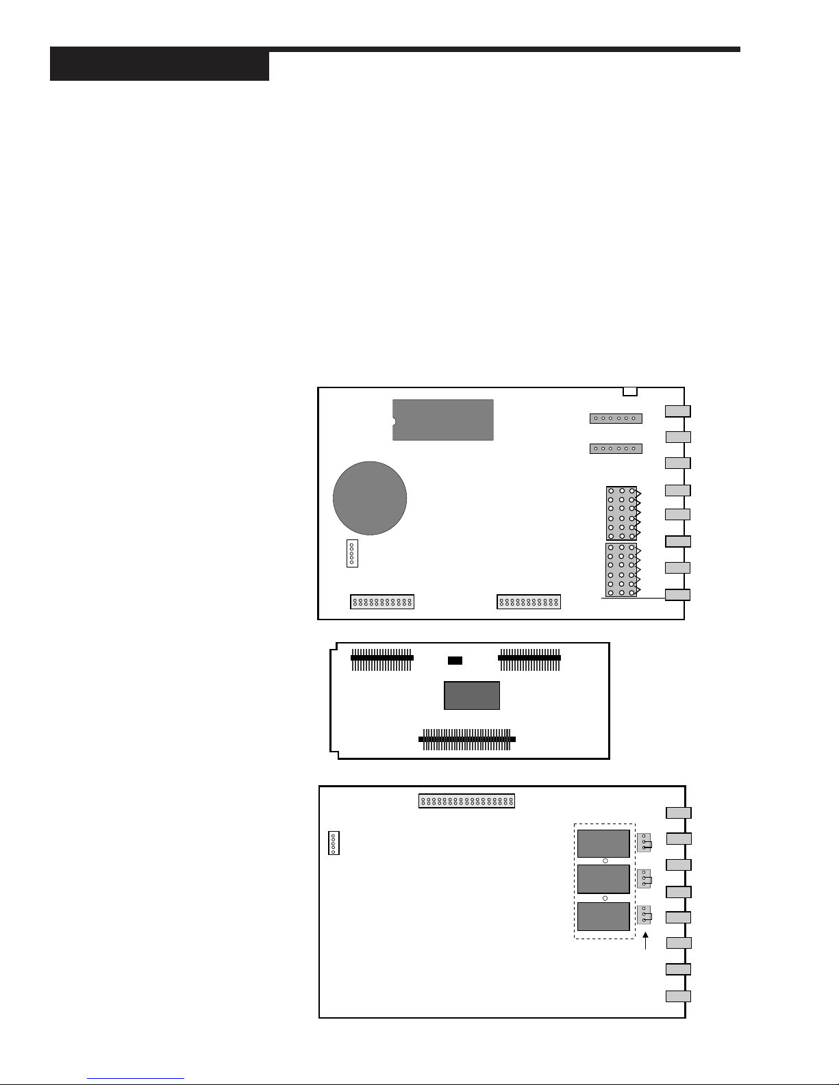
A detailed view of the circuit boards appears in
S
O
U
A
P
R
P
D
L
Y
OPTION BOARD
Figure 4.2
.
After configuring the hardware, or if no changes are necessary, continued setting up the process as needed.
HARDWARE INPUT TYPES
The Process Variable
The 535-PROF accepts several different types of process variable signals. Set
a jumper location to specify the type of input signal. Set the signal range in the
software (see Chapter 5 for software menus, or Chapter 7 for applications).
The jumpers for the process variable are located on the Microcontroller Circuit
Board (see
as follows:
Figure 4.2
). The factory default is Milliamp. Locations are marked
V Voltage
MA Milliamp
TC Thermocouple with downscale burnout
TC Thermocouple with upscale burnout
RTD RTD
Figure 4.1
Location of Printed Circuit Boards for
Hardware Configuration
NOTE: Thermocouple downscale and
upscale burnout offers a choice in
which direction the controller would
react in the event of thermocouple
failure. For example, in heat
applications, typically, it is desirable
to fail upscale (TC ) so that the
system does not apply more heat.
535-PROF User's Manual Chapter 4 21
Page 31
Hardware Set Up
BATTERY
EPROM
NOTE:
Changing the jumpers means moving
the jumper connector. The jumper
connector slips over the pins,
straddling two rows of pins. The
printed circuit boards are labeled next
to the jumpers.
Figure 4.2
(from the top) The Microcontroller
Circuit Board, the Option Board, and
the Power Supply Board
The Remote Setpoint
Figure 4.2
fault is milliamp. Choose from the following settings:
MA Remote setpoint with milliamp signal (jumper installed)
shows the location of the remote setpoint jumper. The factory de-
V Remote setpoint with voltage signal (jumper removed)
Mechanical Relays
There are three output module sockets on the Power Supply Circuit Board, and
one output module on the Option Board (see
on the Power Supply Board may be configured for either normally open (NO) or
normally closed (NC). A jumper located next to each socket determines this
configuration. All relay output are factory set to NO (normally open).
EPROM
BATTERY
5-Pin Connector
Female 22-Pin ConnectorFemale 22-Pin Connector
Figure 4.2
). The mechanical relay
P1
P2
TB2
V
V
V
MA
MA
MA
TC
TC
TC ▼
TC
TC
TC ▲
2ND
RTD
RTD
RTD
V
MA
TC ▼
TC ▲
PV1
RTD
TB1
Remote Setpoint Jumper
Male 22-Pin
Connector
5-Pin Connector
Output 4
4
Female 34-Pin Connector
Male 22-Pin
Connector
Male 34-Pin
Connector
Module
Retention
over Outputs 1,2,3
Plate
3
2
NO J3 NC
NO J2 NC
1
NO J1 NC
Jumpers
NO and NC
22 Chapter 4 535-PROF User's Manual
Page 32
Hardware Set Up
ACCESSING AND CHANGING JUMPERS
Follow these instruction to change jumpers for the Process Variable, Remote
Setpoint and Digital Inputs:
Equipment needed: Needle-nose pliers (optional)
Phillips screwdriver (#2)
Wrist grounding strap
1. With power off, loosen the four front screws, and remove them.
2. Side the chassis out of the case by pulling firmly on the bezel.
3. Use
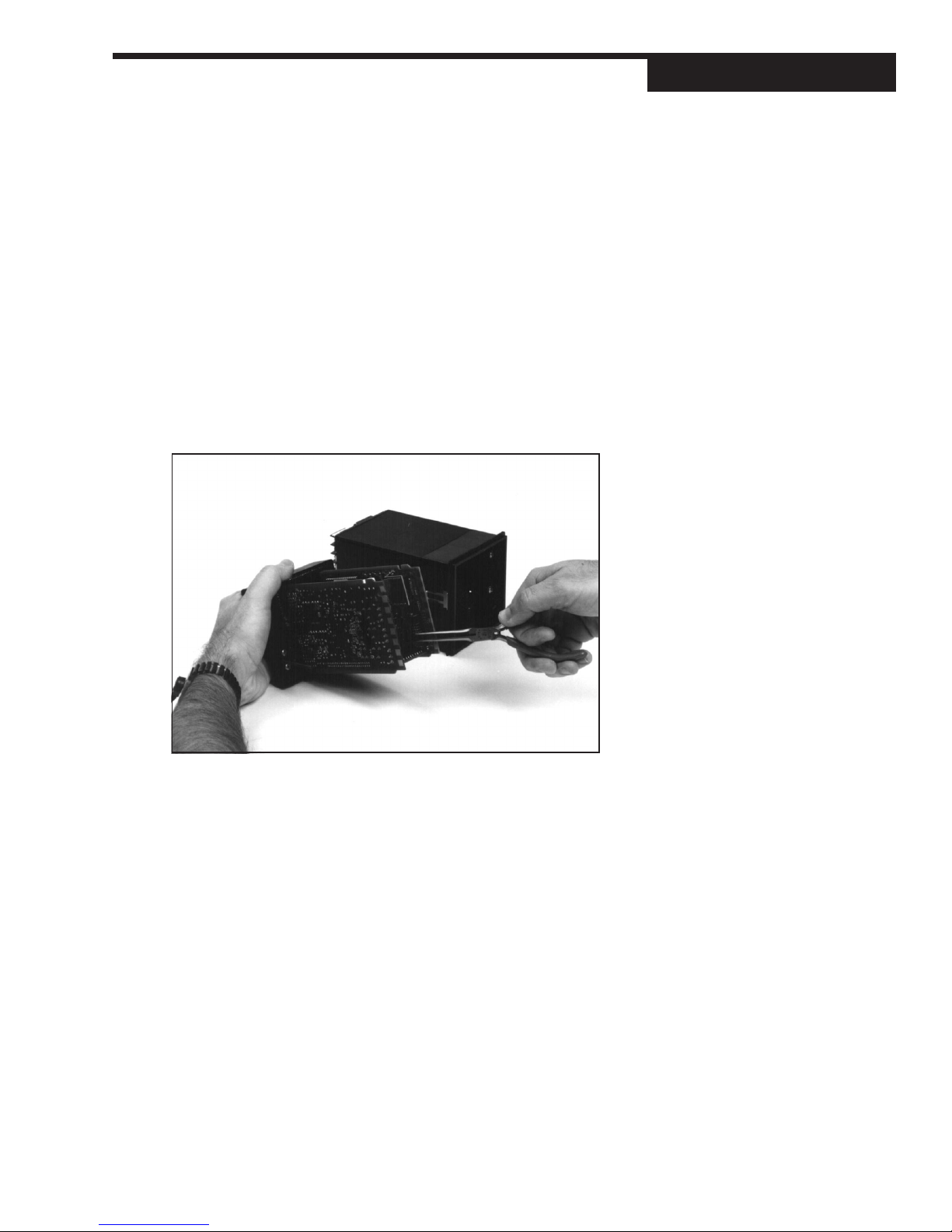
4. Using the needle nose pliers (or fingers), pull straight up on the connector
Figure 4.2
and remove it from its pins, as shown in
pins.
to locate the jumper connector to change.
Photo 2
. Be careful not to bend the
CAUTION!!
Static discharge can cause damage to
equipment. Always use a wrist
grounding strap when handling
electronics to prevent static discharge.
2. Remove Jumpers
5. Find the new location of the jumper connector (again, refer to
Carefully place it over the pins, then press connector straight down. Make
sure it is seated firmly on the pins.
6. Make any other jumper changes as needed. To alter output modules,
please refer to the next section, starting with Step #3.
7. To reassemble the controller, properly orient the chassis with board opening on top. Align the circuit boards into the grooves on the top and bottom of
the case. Press firmly on the front face assembly until the chassis is all the
way into the case.
If it is difficult to slide the chassis in all the way, make sure the screws have
been removed (they can block proper alignment), and that the chassis is
properly oriented.
8. Carefully insert and align screws. Tighten them until the bezel is seated firmly
against the gasket. Do not overtighten.
535-PROF User's Manual Chapter 4 23
Figure 3.2
).
Page 33
Hardware Set Up
ADDING AND CHANGING OUTPUT MODULES
The 535-PROF has provisions for four output modules. A controller ordered with
output module options already has the modules properly installed. Follow these
instruction to add modules, change module type(s) or change module location(s).
Equipment needed: Wrist grounding strap
Phillips screwdriver (#2)
Small flat blade screwdriver
Wire cutters
1. With power off, loosen the four front screws, and remove them.
2. Side the chassis out of the case by pulling firmly on the bezel.
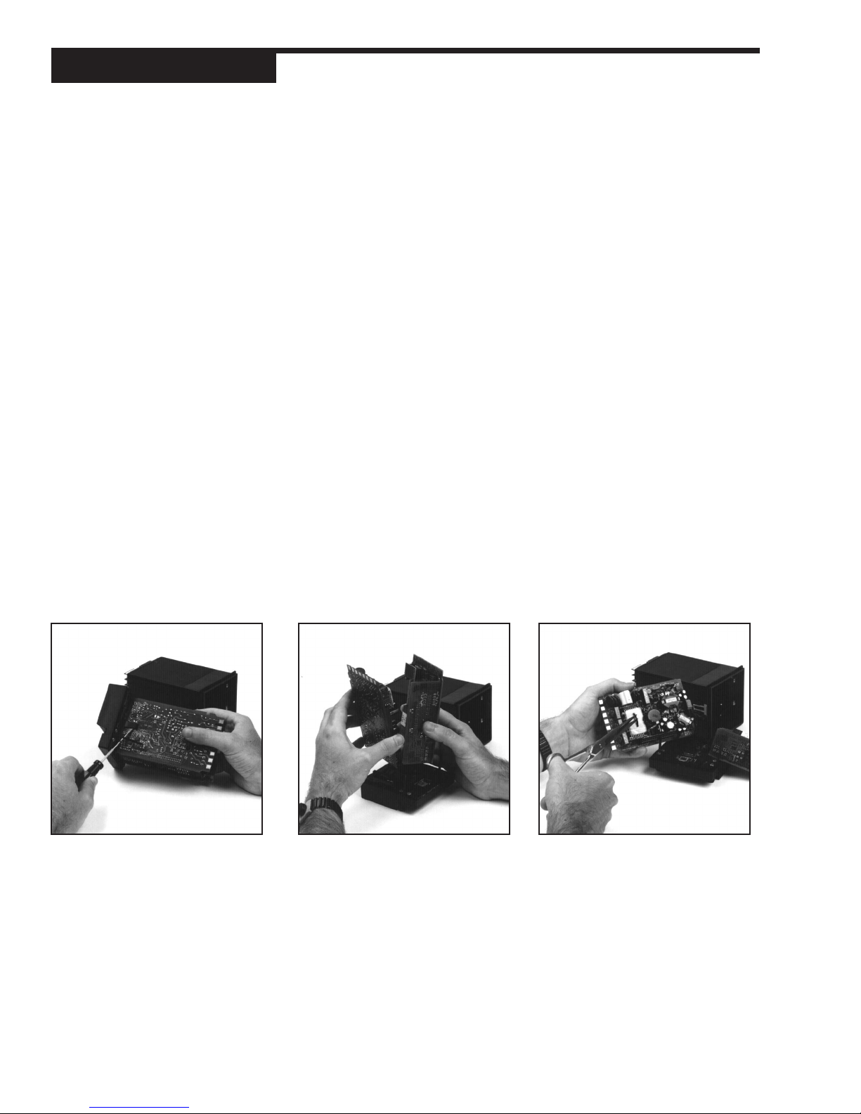
3. Use a flat screwdriver to carefully pry apart the clips that hold the front face
assembly to the chassis, as in Photo 3. Separate the printed circuit board
assembly from the front face assembly. Use care not to break the clips or
scratch the circuit boards.
4. As shown in
driver, the smaller Option board and the Power Supply board (the one with 3
modules).
5. To change modules 1, 2 or 3:
Output modules 1, 2, and 3 are firmly held in place by a retention plate and
tie wrap. Carefully snip the tie wrap with a wire cutter. To prevent damage to
the surface mount components, ALWAYS snip the tie wrap on TOP of the
Retention Plate, as shown in
Remove the retention plate.
Photo 4
, carefully pry apart, using hands or a small flat screw-
Photo 5
.
3. Pry Clips
24 Chapter 4 535-PROF User's Manual
4. Separate Boards
5. Remove Retention Plate
Page 34
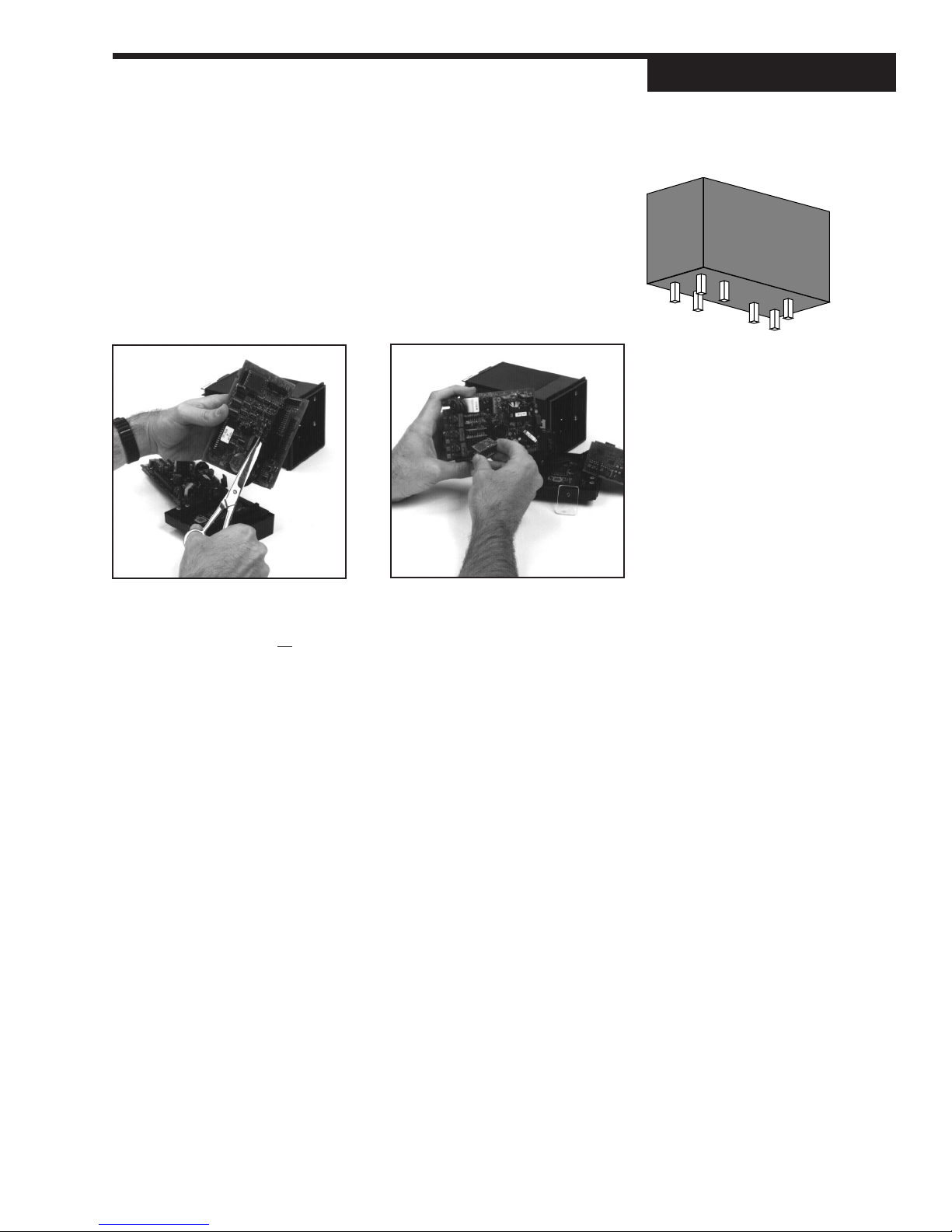
6. To change module 4:
Output Module 4 (on the Option board) is also held in place by a tie wrap.
Snip tie wrap to remove module as shown in
7.
Figure 4.3
to make sure that the pins are straight.
8. To install any module, align its pins with the holes in the circuit board, and
carefully insert the module in the socket. Press down on the module until it
is firmly seated; refer to
shows a representation of an output module. Inspect the module(s)
Photo 7
.
Photo 6
.
Hardware Set Up
Figure 4.3
Representation of Module
7. Add/Change Module6. Snip Tie Wrap
9. Replace tie wraps for all the modules (the Retention Plate and Output Mod-
ule 4) with new ones before reassembling the controller.
Failure to use the tie wraps may result in loosening of the module and even-
tual failure. All separately ordered modules should come with a tie wrap. Extra
sets of tie wraps are available by ordering Part #535-PROF-665.
NOTE: For greatest accuracy, calibrate all milliamp modules added for
retransmission as per the instructions in Appendix 2.
10. Rejoin the circuit boards by aligning the pins of their connectors, then squeez-
ing the board(s) together. Make sure that all three printed circuit boards are
properly seated against one another; check along side edges for gaps. Make
sure the cable assemblies are not pinched.
11. To reattach the board assembly to the front face assembly, align the boards
(with the open area on top) into the slots of the font face assembly. The clips
should snap into place.
12.To reassemble the controller, properly orient the chassis with board open-
ing on top. Align the circuit boards into the grooves on the top and bottom of
the case. Press firmly on the front face assembly until the chassis is all the
way into the case.
If it is difficult to slide the chassis in all the way, make sure the screws have
been removed (they can block proper alignment), and that the chassis is
properly oriented.
13. Carefully insert and align screws. Tighten them until the bezel is seated firmly
against the gasket. Do not overtighten.
535-PROF User's Manual Chapter 4 25
Page 35
Hardware Set Up
SPECIAL COMMUNICATIONS MODULE
A special communications module is available for the 535-PROF; see order code
in Chapter 1 for details.
Equipment needed: Wrist grounding strap
Phillips screwdriver (#2)
Small flat blade screwdriver
1. Before installing the communications module, set up the hardware wiring
for the application. See Chapter 4 for details.
2. With power off, loosen the four front screws, and remove them.
3. Side the chassis out of the case by pulling firmly on the bezel. Do not detach
the board assembly form the front face of the controller.
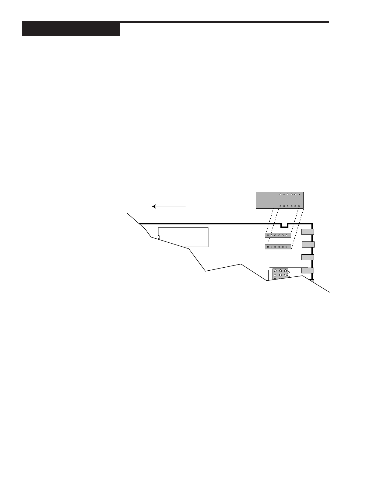
4. Orient the Communications Module as shown, and attach it to Connectors
P1 and P2 as shown in
Figure 4.4
.
Insert module onto connectors
Figure 4.4
Install Communications Module onto
Microcontroller Board
Front of controller
(circuits boards still attached to front face)
EPROM
P1
P2
TB2
V
BATTERY
5. To reassemble the controller, properly orient the chassis with board open-
REMOTE SP
CONFIGURATION
PV INPUT
JUMPER
CONFIGURATION
ing on top. Align the circuit boards into the grooves on the top and bottom of
the case. Press firmly on the front face assembly until the chassis is all the
way into the case.
ASS'Y 535-607
MA
TCt
TCs
RTD
V
MA
TCt
TCs
RTD
2ND
PV1
TB1
If it is difficult to slide the chassis in all the way, make sure the screws have
been removed (they can block proper alignment), and that the chassis is
properly oriented.
6. Carefully insert and align screws. Tighten them until the bezel is seated firmly
against the gasket. Do not overtighten.
26 Chapter 4 535-PROF User's Manual
Page 36
CHAPTER 5
SOFTWARE CONFIGURATION
The software configuration menus of the 535-PROF contain user-selected variables that define the action of the controller. Read through this section before
making any parameter adjustments to the controller.
Controller Set Up
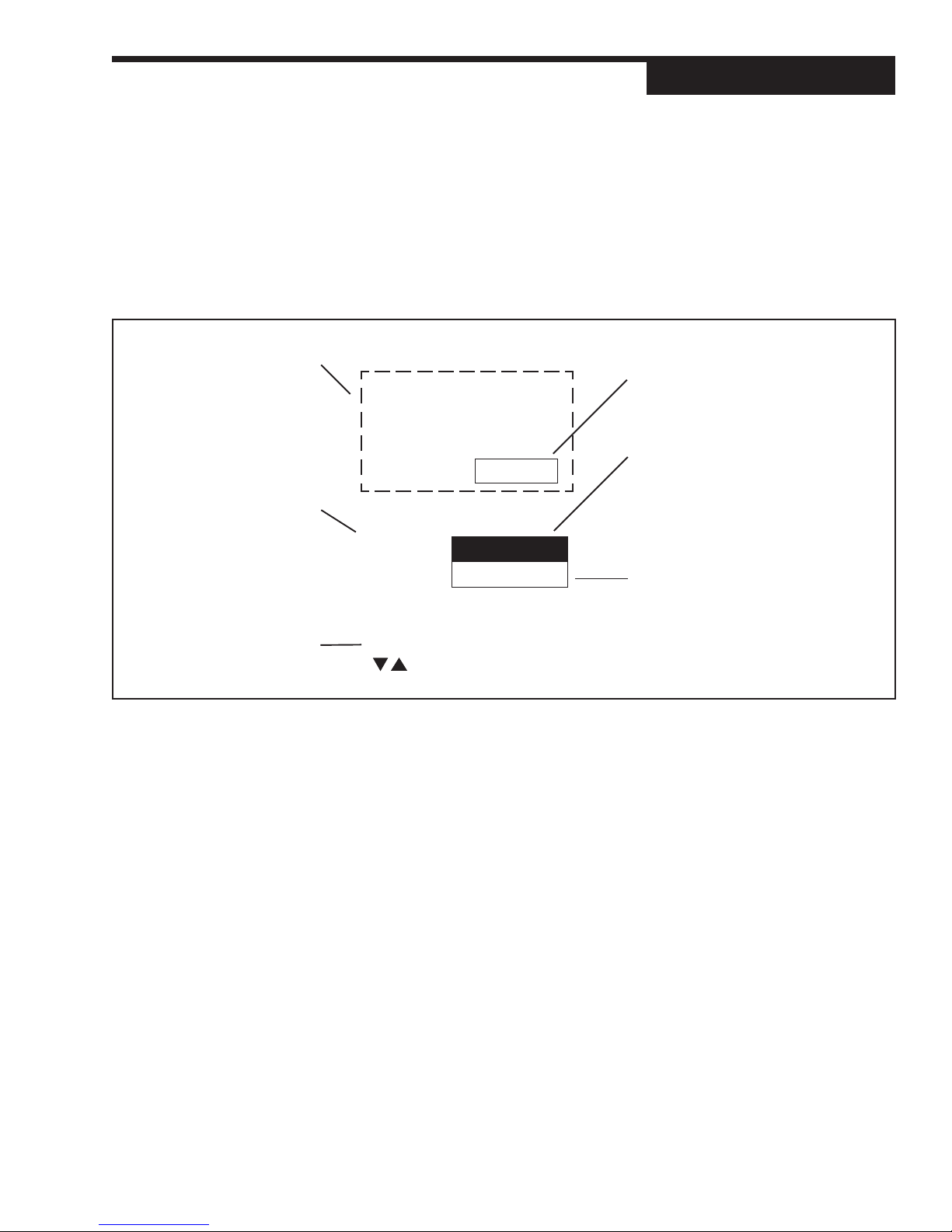
Figure 5.1
Menu Flowchart for Set Up
When initially setting up the
controller, cycle through all the
parameters in each Menu.
Press the MENU+FAST to
advance to the next Menu.
➤
press:
MENU/FAST
➤
Press MENU to advance to the
next parameter (this also sets
the value for the current
parameter. Use arrow keys
to select a value).
Use the arrow keys to enter
numerical values, and/or move
through the selection group.
➤
➤
press:
MENU
Go to next Menu Block
press:
CONFIG.
➤
INDICATOR
(D)
press MENU/FAST
➤
MENUS
In Set Up mode, there are 13 sets of options that control different aspects of 535PROF operation; in Tuning mode, there is one. Each set of options is a menu. When
traversing the two modes, the menu names appear in the 2nd display.
CONFIG Mode selection and input/output hardware assignments
REC. CONF. General recipe options
PV1 INPUT 1st process variable input options
PV2 INPUT 2nd process variable input options
CUST. LINR. Linearization curve options for PV1 input.
CONTROL Control algorithm options
ALARMS Alarm options
REM. SETPT. Controller re mote setpoint options
RETRANS. Retransmission output options
SELF TUNE Self tune algorithm options
SPECIAL Special feature options
SECURITY Security functions
SER.COMM. Serial Communications options (requires comm. board)
RECIPE # Individual recipe configuration
TUNING Tuning parameters configuration (see Chapter 6)
This is a Menu.
Its name will show in the 2nd display.
This is a menu Parameter.
The name shows in the 3rd display.
In this manual, independent parameters
appear as white text on black, and
dependent parameters appear as black
text on white.
This is a parameter Value.
These values appear in the 3rd display,
replacing the parameter name.
In this manual, parameter graphics
indicate the default (factory) setting.
If the default value is dependent on other
variables, (D) is shown.
A range of values is indicated by (R).
CAUTION!
All software changes occur in real
time; always perform set up functions
under manual operation.
NOTE: For information about the
Tuning menu/mode, refer to Chapter
6. For more information about set up
parameters and 535-PROF
applications, refer to Chapter 7.
535-PROF User's Manual Chapter 5 27
Page 37
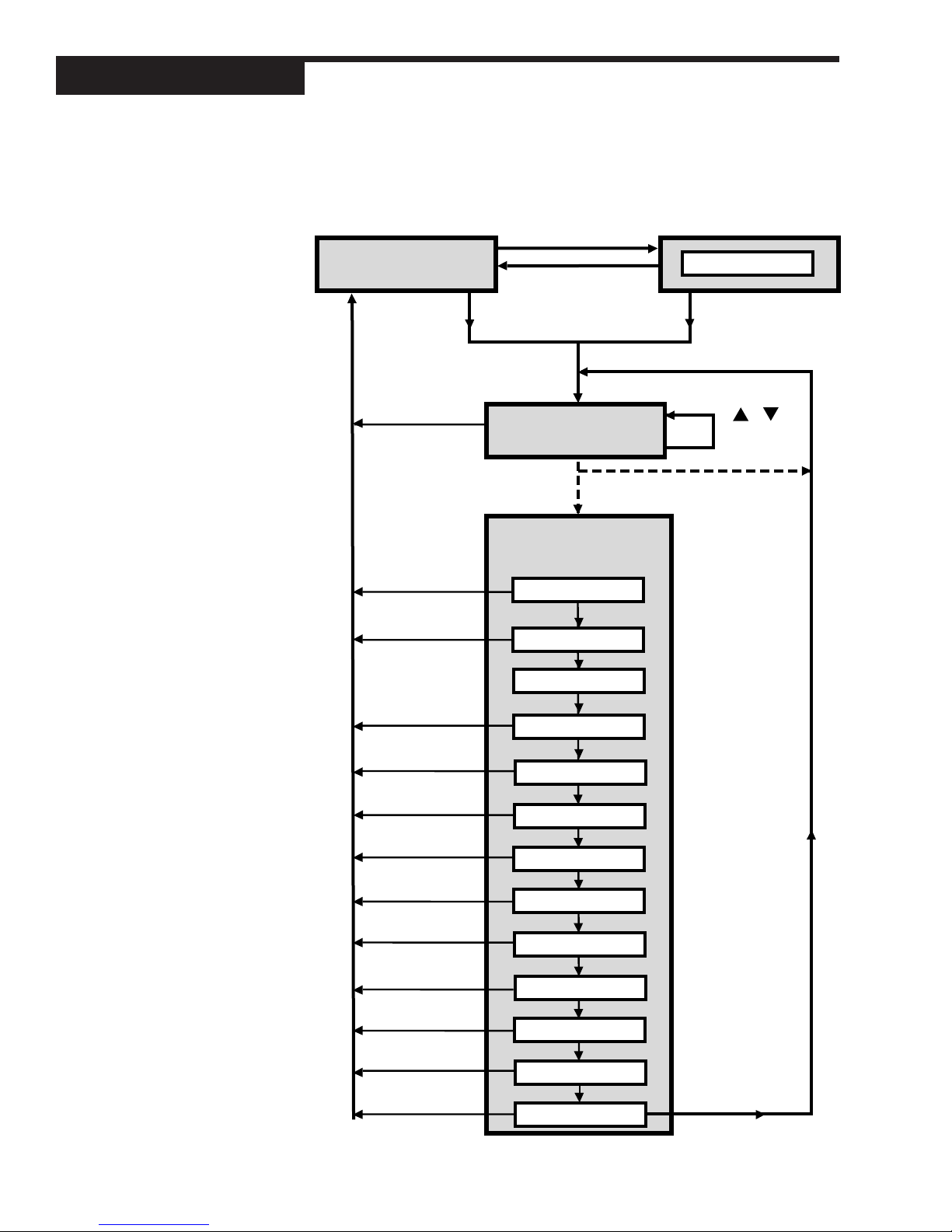
Controller Set Up
Figure 5.2
Configuration Flowchart
MANUAL
to place controller
under Manual Control
MANUAL
OPERATION
MENU
TUNING
DISPLAY
FAST + MENU
DISPLAY
DISPLAY
to return to
operation mode
RECIPE #
*
FAST + MENU
SET UP
(Configuration) Menus
CONFIG.
REC. CONF.
*
PV1 INPUT
PV2 INPUT
CUST. LINR.
CONTROL
ALARMS
or
to scroll
thru recipes
Set Up Mode
is only accessible if
controller is under
Manual Control.
* Define # of recipes
in REC. CONF. menu
FAST + MENU
to scroll through
the menu blocks
28 Chapter 5 535-PROF User's Manual
REM. SETPT.
RETRANS.
SELF TUNE
SPECIAL
SECURITY
SER. COMM.
Page 38
Controller Set Up
PARAMETERS
Within each menu are parameters for particular control functions. Select values for each parameter depending on the specific application. Use the MENU
key to access parameters for a particular menu; the parameter name will replace the menu name in the 2nd display, and the parameter value will show in
the 3rd display.
This chapter outlines all the available parameters for the 535-PROF. Some parameters are independent of any special configuration, and others are depen-
dent on the individual configuration. This manual displays these two types of
parameters differently; refer to
Figure 5.3
. A special feature of the 535-PROF,
called Smart Menus, determines the correct parameters to display for the spe-
cific configuration, so not all the listed parameters will appear.
CONFIGURATION AND OPERATION
Figure 5.3
and the configuration menus:
• SET UP menus can only be accessed from manual control. To transfer the
• To access the SET UP menus, hold down FAST and press MENU until
• To access the parameters for a particular menu, press MENU.
• To select a parameter value, use and . Press MENU to advance to the
• To advance to the next menu, press FAST+MENU.
• TUNING mode (and the TUNING menu) can be accessed from either auto-
• RECIPE SET UP mode (and the RECIPE # menu) can be accessed from
• To access the RECIPE # menu, press FAST+MENU.
• To return controller to manual control, press DISPLAY or SET PT.
shows the relationships among the different modes of the 535-PROF
535-PROF from automatic to manual control, press MANUAL.
CONFIG appears in the 2nd display. The MENU key will also illuminate.
next parameter, or FAST+MENU to advance to the next menu.
matic or manual control. To access the tuning menu, press MENU .
either automatic or manual control.
TUNE PT.
AUTOMATIC
Figure 5.3
Independent vs. Dependent
Parameters
CONTACT 1
MANUAL
Access Set Up Return to Operation Next menu Next parameter Next value Access Tuning Return to Operation
+
FAST MENU
DISPLAY
A key to these functions (as shown below) appears at the bottom of every page
in the menu section of this chapter.
WHERE TO GO NEXT
• For information about all the software menus and parameters, continue reading this chapter. Refer to Appendix D for a quick-reference flowchart of all
menus and parameters.
• For information about the installed options on the 535-PROF, compare the
product label on top of the controller to the order code in Chapter 1.
• To mount the controller and configure the wiring of the 535-PROF for inputs
and outputs, see Chapter 3.
• To alter the output module and jumper configuration of the controller, see
Chapter 4.
535-PROF User's Manual Chapter 5 29
+
FAST MENU
MENU
▲ ▼
MENU
DISPLAY
Page 39

Controller Set Up
• For information about applications for the 535-PROF, see Chapter 7.
• For more information about the Tuning function of the 535-PROF, see Chapter 6.
Access Set Up Return to Operation Next menu Next paramet er Next value Access Tuning Return to Operation
+
FAST MENU
DISPLAY
FAST MENU
30 Chapter 5 535-PROF User's Manual
+
MENU
▲ ▼
MENU
DISPLAY
Page 40
SOFTWARE MENUS AND PARAMETERS
Controller Set Up
CONFIG.
1. CTRL. TYPE
Defines the type of control output(s).
D STANDARD Standard control output, no special algorithms
• POS. PROP. Position proportioning control output
• STAGED Staged outputs
• DUPLEX Duplex outputs
2. LINE FREQ
Defines the power source frequency.
• 50 HZ
D 60 HZ
3. PV SOURCE
Defines how the PV input is derived from PV1 and PV2.
D PV1 Use PV1
• 1/2:SWITCH Use PV1 until contact/com selects PV2
• 1/2:BACKUP Use PV2 if PV1 is broken
• PV1–PV2 Use PV1–PV2
• PV1+PV2 Use PV1+PV2
• AVG. PV Use the average of PV1 and PV2
• HI SELECT Use PV1 or PV2 (whichever is greater)
• LO SELECT Use PV1 or PV2 (whichever is less)
CONFIG.
CTRL. TYPE
STANDARD
LINE FREQ
60 Hz
PV SOURCE
PV1
NOTE:
PV1 and PV2 can be of different types
and different range.
4. REM. SETPT.
Selects function of the remote setpoint.
D DISABLED
• ENABLED
REM. SETPT.
DISABLED
5. OUTPUT 2
Defines the function of the second output.
• ALM/EV:ON For an alarm or event output
• ALM/EV:OFF For an alarm or event output
• RETRANS. Retransmission
• COMM. ONLY Output addressable only through
communication
D OFF Completely deactivates the output
Access Set Up Return to Operation Next menu Next paramet er Next value Access Tuning Return to Operation
+
FAST MENU
535-PROF User's Manual Chapter 5 31
DISPLAY
+
FAST MENU
MENU
▲ ▼
OUTPUT 2
OFF
MENU
DISPLAY
Page 41
Controller Set Up
OUTPUT 3
OFF
6. OUTPUT 3
Defines the function of the third output.
• ALM/EV:ON For an alarm or event output
• ALM/EV:OFF For an alarm or event output
• RETRANS. Retransmission
• COMM. ONLY Output addressable only through
communications
D OFF Completely deactivates the output
OUTPUT 4
OFF
ANLG.RNG.:1
4-20 mA
ANLG.RNG.:2
4-20mA
7. OUTPUT 4
Defines the function of the fourth output.
• ALM/EV:ON For an alarm or event output
• ALM/EV:OFF For an alarm or event output
• RETRANS. Retransmission
• COMM. ONLY Output addressable only through
communications
D OFF Completely deactivates the output
8. ANLG. RNG.:1
Defines the output signal for the first output.
D 4–20 mA
• 0–20 mA
• 20–4 mA
• 20–0 mA
9. ANLG. RNG.:2
Defines the output signal for the second output.
D 4–20 mA
• 0–20 mA
• 20–4 mA
• 20–0 mA
ANLG.RNG.:3
4-20mA
ANLG.RNG.:4
4-20mA
Access Set Up Return to Operation Next menu Next paramet er Next value Access Tuning Return to Operation
+
FAST MENU
32 Chapter 5 535-PROF User's Manual
DISPLAY
FAST MENU
10. ANLG. RNG.:3
Defines the output signal for the third output.
D 4–20 mA
• 0–20 mA
• 20–4 mA
• 20–0 mA
11. ANLG. RNG.:4
Defines the output signal for the fourth output.
D 4–20 mA
• 0–20 mA
• 20–4 mA
• 20–0 mA
+
MENU
▲ ▼
MENU
DISPLAY
Page 42

12. CONTACT 1
Defines the operation of the first digital input.
• RECIPE. 1–7 Chooses the recipe number (uses Binary contact
1-3)
• SETPT. 1–8 Chooses Local setpoint 1–8 (uses BCD contacts
1–4)
• REM. SETPT. Makes the remote setpoint active
D MANUAL Trips the controller to manual control
• 2ND. SETPT. Makes the second setpoint active
• 2ND. PID Makes the second set of PID values active
• ALARM ACK. Acknowledges alarms
• RST. INHBT. Deactivates the reset term
• D.A./R.A. Switches the control action
• STOP A/T Suspends the adaptive tune function
• LOCK. MAN. Locks controller in manual control
• UP KEY Remote function
• DOWN KEY Remote function
• MENU KEY Remote MENU key function
• FAST KEY Remote FAST key function
• DISP KEY Toggle between SP DEV or OUT%
• COMM. ONLY Status readable only through communications
• START REC. Runs the most recently selected recipe (default is RECIPE 1). Aborts recipe when deactivated.
• HOLD REC. Holds running recipe at current position. Resumes running of recipe when deactivated.
• RESET REC. Resets a running or held recipe to the beginning. For linked recipes, resets to the beginning
of the first linked recipe. No action when deactivated.
• ABORT REC. Aborts running or held recipe. No action when
deactivated.
• NEXT SEG. Advances running or held recipe to the end of
the current ramp or soak segment. No action
when deactivated
• PV2.SWITCH Switches between PV1 and PV2
Controller Set Up
CONTACT 1
MANUAL
Access Set Up Return to Operation Next menu Next paramet er Next value Access Tuning Return to Operation
+
FAST MENU
535-PROF User's Manual Chapter 5 33
DISPLAY
+
FAST MENU
MENU
▲ ▼
MENU
DISPLAY
Page 43

Controller Set Up
CONTACT 2
REM. SETPT.
13. CONTACT 2
Defines the operation of the second digital input.
D REM. SETPT.
• MANUAL
• 2ND. SETPT.
• 2ND. PID
• ALARM ACK.
• RST. INHBT.
• D.A./R.A.
• STOP A/T
• LOCK. MAN.
• UP KEY
• DOWN KEY
• MENU KEY
• FAST KEY
• DISP KEY
• COMM. ONLY
• START REC.
• HOLD REC.
• RESET REC.
• ABORT REC.
• NEXT SEG.
• PV2.SWITCH
Access Set Up Return to Operation Next menu Next paramet er Next value Access Tuning Return to Operation
+
FAST MENU
DISPLAY
FAST MENU
34 Chapter 5 535-PROF User's Manual
+
MENU
▲ ▼
MENU
DISPLAY
Page 44

14. CONTACT 3
Defines the operation of the third digital input.
• REM. SETPT.
• MANUAL
D 2ND. SETPT.
• 2ND. PID
• ALARM ACK.
• RST. INHBT.
• D.A./R.A.
• STOP A/T
• LOCK. MAN.
• UP KEY
• DOWN KEY
• MENU KEY
• FAST KEY
• DISP KEY
• COMM. ONLY
• START REC.
• HOLD REC.
• RESET REC.
• ABORT REC.
• NEXT SEG.
• PV2.SWITCH
Controller Set Up
CONTACT 3
2ND. SETPT.
Access Set Up Return to Operation Next menu Next paramet er Next value Access Tuning Return to Operation
+
FAST MENU
535-PROF User's Manual Chapter 5 35
DISPLAY
+
FAST MENU
MENU
▲ ▼
MENU
DISPLAY
Page 45

Controller Set Up
CONTACT 4
2ND. PID
15. CONTACT 4
Defines the operation of the fourth digital input.
• REM. SETPT.
• MANUAL
• 2ND. SETPT.
D 2ND. PID
• ALARM ACK.
• RST. INHBT.
• D.A./R.A.
• STOP A/T
• LOCK. MAN.
• UP KEY
• DOWN KEY
• MENU KEY
• FAST KEY
• DISP KEY
• COMM. ONLY
• START REC.
• HOLD REC.
• RESET REC.
• ABORT REC.
• NEXT SEG.
• PV2.SWITCH
Access Set Up Return to Operation Next menu Next paramet er Next value Access Tuning Return to Operation
+
FAST MENU
DISPLAY
FAST MENU
36 Chapter 5 535-PROF User's Manual
+
MENU
▲ ▼
MENU
DISPLAY
Page 46
16. CONTACT 5
This defines the operation of the fifth digital input.
• REM. SETPT.
• MANUAL
• 2ND. SETPT.
• 2ND. PID
D ALARM ACK.
• RST. INHBT.
• D.A./R.A.
• STOP A/T
• LOCK. MAN.
• UP KEY
• DOWN KEY
• MENU KEY
• FAST KEY
• DISP KEY
• COMM. ONLY
• START REC.
• HOLD REC.
• RESET REC.
• ABORT REC.
• NEXT SEG.
• PV2.SWITCH
Controller Set Up
CONTACT 5
ALARM ACK.
17. LOOP NAME
A 9-character message associated with the loop. The first character of the 3rd
display will be flashing. To enter message, press and keys to scroll
through character set. Press FAST key to enter the selection and move to
next digit. Press MENU key to advance to next parameter.
D LOOP ONE
REC. CONF.
LOOP NAME
LOOP ONE
REC. CONF.
1. RECIPES
Defines the number of recipes available in the 535.
• NONE
R 1 to 20
D 1
RECIPES
1
2. TIME BASE
Defines time base units for recipes.
D HOURS:MIN.
• MIN:SEC.
Access Set Up Return to Operation Next menu Next paramet er Next value Access Tuning Return to Operation
+
FAST MENU
DISPLAY
+
FAST MENU
MENU
▲ ▼
TIME BASE
HOUR:MIN.
MENU
DISPLAY
535-PROF User's Manual Chapter 5 37
Page 47
Controller Set Up
RAMP UNIT
TIME
SP START
PV
GUAR.SOAK
OFF
3. RAMP UNIT
Defines ramp segment terms.
D TIME
• RATE
4. SP START
Defines initial value for the first ramp segment’s setpoint.
• IDLE SP the IDLE SP is the first value
D PV The starting value will be adjusted to account for
the initialPV value
5. GUAR. SOAK
Selects whether guaranteed soak is used during each soak segment.
D OFF guaranteed soak will not occur
• START SEG. guaranteed soak can occur only at the start of a
soak segment
• WHOLE SEG. guaranteed soak can occur at the start of or at
anytime during a soak segment
EVT.:1 OUT.
NONE
EVT.:2 OUT.
NONE
EVT.:3 OUT.
NONE
6. EVT.:1 OUT.
Selects which output is assigned to event 1. To assign a numerical value (nondefault), the corresponding output needs to be set to ALM/EV:ON or ALM/EV:OFF.
D NONE
•2
•3
•4
7. EVT.:2 OUT.
Selects which output is assigned to event 2. To assign a numerical value (non-default), the corresponding output needs to be set to ALM/EV:ON or ALM/EV:OFF.
D NONE
•2
•3
•4
8. EVT.:3 OUT.
Selects which output is assigned to event 3. In order to assign a numerical
value (non-default), the corresponding output needs to be configured as ALM/
EV:ON or ALM/EV:OFF.
D NONE
•2
•3
•4
Access Set Up Return to Operation Next menu Next paramet er Next value Access Tuning Return to Operation
+
FAST MENU
38 Chapter 5 535-PROF User's Manual
DISPLAY
FAST MENU
+
MENU
▲ ▼
MENU
DISPLAY
Page 48
9. HOLD EVT.
Selects whether or not the last segment’s event(s) will be held active after the
recipe has been successfully completed.
D DISABLED
• ENABLED
PV1 INPUT
1. PV1 TYPE
Specifies the particular sensor range or input range for PV1.
T/C RTD VOLTAGE CURRENT (mA)
D J T/C D DIN RTD D 1-5 V D 4-20mA
• E T/C • JIS RTD • 0-5 V • 0-20mA
• K T/C • SAMA RTD • 0-10 mV
• B T/C • 0-30 mV
• N T/C • 0-60 mV
• R T/C • 0-100 mV
• S T/C • +/– 25 mV
• T T/C
• W T/C
• W5 T/C
• PLAT.II T/C
Controller Set Up
HOLD EVT.
DISABLED
PV1 INPUT
PV1 TYPE
J T/C
2. DEG. F/C/K
Selects the PV1 temperature units if using a thermocouple or RTD.
D FAHR.
• CELSIUS
• KELVIN
3. DECIMAL
Specifies the PV1 decimal point position.
D XXXXX
• XXXX.X
• XXX.XX
• XX.XXX
• X.XXXX
4. LINEARIZE
Specifies if the PV1 input is to be linearized. NOTE: T/C’s and RTD’s are automatically linearized.
D NONE
• SQR. ROOT Square root linearization is activated.
• CUSTOM 15-point custom linearization curve is activated.
DEG. F/C/K
FAHR
DECIMAL
XXXXX
LINEARIZE
NONE
Access Set Up Return to Operation Next menu Next paramet er Next value Access Tuning Return to Operation
+
FAST MENU
535-PROF User's Manual Chapter 5 39
DISPLAY
+
FAST MENU
MENU
▲ ▼
MENU
DISPLAY
Page 49
Controller Set Up
LOW RANGE
(D)
HI RANGE
(D)
SP LO LIM.
(D)
SP HI LIM.
(D)
5. LOW RANGE
Specifies the engineering unit value corresponding to the lowest PV1 input
value, e.g. 4 mA.
R –9999 to 99999 Max. is HI RANGE
D Dependent on the input selection
6. HI RANGE
Specifies the engineering unit value corresponding to the highest PV1 input
value, e.g., 20mA.
R -9999 to 99999 Min. is LOW RANGE
D Dependent on the input selection
7. SP LO LIM.
Defines the lowest setpoint value that can be entered from the front panel only.
R –9999 to 99999 Max. is SP HI LIM. Min. is LOW RANGE
D Dependent on the LOW RANGE value.
8. SP HI LIM.
Defines the highest setpoint value that can be entered from the front panel only.
R –9999 to 99999 Min. is SP LO. LIM. Maximum is HI RANGE
D Dependent on HI RANGE
CAUTION!
Set parameter values in the presented
order—dependent parameters are dynamically related and changing values of
one can alter the value of another.
For example, if SP LO LIM. is set to 0, and
then thermocouple type is changed to B
T/C, the SP LO LIM. value will change to
104° (the low limit of a type B
thermocouple).
SP RAMP
OFF
FILTER
0
OFFSET
0
9. SP RAMP
Defines the rate of change for setpoint changes.
D OFF Deactivates this function
R 1 to 99999 units per hour
10. FILTER
Setting for the low pass PV1 input filter.
R 0 to 120 seconds
D 0 seconds
11. OFFSET
Defines the offset to PV1 in engineering units.
R –9999 to 99999
D 0
Access Set Up Return to Operation Next menu Next paramet er Next value Access Tuning Return to Operation
+
FAST MENU
40 Chapter 5 535-PROF User's Manual
DISPLAY
FAST MENU
+
MENU
▲ ▼
MENU
DISPLAY
Page 50
12. GAIN
Defines the gain to PV1.
R 0.100 to 10.000
D 1.000
13. RESTORE
Defines the control mode when a broken PV1 signal is restored.
D LAST MODE
• MANUAL
• AUTOMATIC
• START REC.
• RESUME.REC.
• HOLD REC.
Controller Set Up
GAIN
1.000
RESTORE
LAST MODE
PV2 INPUT
1. PV2 SETUP
Defines function of PV2
D SAME.AS.PV1 All PV2 parameters are set to the same values
as PV1 (no further parameters will appear)
• NOT PV1 Enables user to enter different values for the following PV2 parameters
2. PV2 TYPE
Selects the particular sensor or input range for PV2
T/C RTD VOLTAGE CURRENT (mA)
D J T/C D DIN RTD D 1-5 V D 4-20mA
• E T/C • JIS RTD • 0-5 V • 0-20mA
• K T/C • SAMA RTD • 0-10 mV
• B T/C • 0-30 mV
• N T/C • 0-60 mV
• R T/C • 0-100 mV
• S T/C • +/– 25 mV
• T T/C
• W T/C
• W5 T/C
• PLAT.II T/C
PV2 INPUT
PV2 SETUP
SAME.AS.PV1
PV2TYPE
J T/C
3. DECIMAL
Specifies the PV2 decimal point position.
D XXXXX
• XXXX.X
• XXX.XX
• XX.XXX
• X.XXXX
Access Set Up Return to Operation Next menu Next paramet er Next value Access Tuning Return to Operation
+
FAST MENU
535-PROF User's Manual Chapter 5 41
DISPLAY
+
FAST MENU
MENU
▲ ▼
DECIMAL
XXXXX
MENU
DISPLAY
Page 51
Controller Set Up
LINEARIZE
NONE
4. LINEARIZE
Specifies if the PV2 input is to be linearized. Thermocouples and RTD’s are
automatically linearized.
D NONE
• SQR. ROOT Square root linearization is activated.
LOW RANGE
(D)
HI RANGE
(D)
FILTER
0
OFFSET
0
GAIN
1.000
5. LOW RANGE
Specifies the engineering unit value corresponding to the lowest PV2 input value,
e.g. 4 mA.
R –9999 to 99999 Max. is HI RANGE
D Dependent on the input selection
6. HI RANGE
Specifies the engineering unit value corresponding to the highest PV2 input value,
e.g. 20 mA.
R -9999 to 99999 Min. is LOW RANGE
D Dependent on the input selection
7. FILTER
Setting for the low pass PV2 input filter.
R 0 to 120 seconds
D 0 seconds
8. OFFSET
Defines the offset to PV2 in engineering units.
R –9999 to 99999
D 0
9. GAIN
Defines the gain for PV2.
R 0.100 to 10.000
D 1.000
RESTORE
LAST MODE
Access Set Up Return to Operation Next menu Next paramet er Next value Access Tuning Return to Operation
+
FAST MENU
42 Chapter 5 535-PROF User's Manual
DISPLAY
FAST MENU
10. RESTORE
Defines the control mode when a broken PV2 signal is restored.
D LAST MODE
• MANUAL
• AUTOMATIC
• START REC.
• RESUME.REC.
• HOLD REC.
+
MENU
▲ ▼
MENU
DISPLAY
Page 52
Controller Set Up
CUST. LINR.
Defines a custom linearization curve for PV1, if selected. Points 1 and 15 are
fixed to the low and high end of the input range and require only setting a
corresponding PV value. Points 2 through 14 (the Xth points) require setting both
the input and PV values.
It is not necessary to use all 15 points. Whenever the XTH INPUT becomes the
high end of the range, that will be the last point in the linearization table.
1. 1ST. INPUT
Specifies the input signal corresponding to the first point.
D The low end of the appropriate input range (e.g. 4.00 mA)
2. 1ST. PV
Specifies the engineering unit value corresponding to the first point.
R –9999 to 99999
D 0
3. XTH. INPUT
Specifies the input signal corresponding to the XTH point (X is 2 to 14).
R Any value greater than the first input
D The low end of the appropriate input range (e.g. 4.00 mA)
4. XTH. PV
Specifies the unit value corresponding to the XTH point (X is 2 to 14).
R –9999 to 99999
D 0
5. 15TH. INPT.
Specifies the input signal corresponding to the 15th point.
R –9999 to 99999 Minimum is [XTH-1] INPUT
D The high end of the appropriate input range (e.g. 20.00 mA)
6. 15TH. PV
Specifies the engineering unit value corresponding to the 15th point.
R –9999 to 99999
D 0
CUST. LINR.
1ST. INPUT
(D)
1ST. PV
0
XTH INPUT
(D)
XTH PV
0
15TH INPT.
(D)
15TH PV
0
Access Set Up Return to Operation Next menu Next paramet er Next value Access Tuning Return to Operation
+
FAST MENU
535-PROF User's Manual Chapter 5 43
DISPLAY
+
FAST MENU
MENU
▲ ▼
MENU
DISPLAY
Page 53
Controller Set Up
CONTROL
ALGORITHM
PID
D. SOURCE
PV
ACTION:1
REVERSE
CONTROL
For configuring the choices for the control algorithm.
1. ALGORITHM
Defines the type of control algorithm.
D PID
•PI
•PD
•P
• ON/OFF
• PID:ON/OFF For Duplex applications using PID for the first
output and on/off for the second output
2. D. SOURCE
Selects the variable for the derivative action.
D PV Derivative term will not react when setpoint
changes
• DEVIATION Derivative term will react when setpoint
changes
3. ACTION:1
Defines the action of the first control output.
• DIRECT
D REVERSE
4. PV BREAK
PV BREAK
(D)
LOW OUT
0
HIGH OUT.
100
ACTION:2
DIRECT
Access Set Up Return to Operation Next menu Next paramet er Next value Access Tuning Return to Operation
+
FAST MENU
DISPLAY
Defines the manual output level if the process variable input is lost. Choose values based on the process type.
Standard Control On/Off Control Velocity Prop Control
• –5 to 105% • ON • CW
D 0 D OFF • CCW
D OUTS. OFF
5. LOW OUT.
Defines the lowest output value that can be achieved in automatic control.
R 0 – 100% Max is HIGH OUT
D 0%
6. HIGH OUT.
Defines the highest output value that can be achieved in automatic control.
R 0 – 100% Min is LOW OUT
D 100%
7. ACTION:2
Defines the action of the second control output.
+
FAST MENU
MENU
▲ ▼
MENU
DISPLAY
44 Chapter 5 535-PROF User's Manual
Page 54
D DIRECT
• REVERSE
8. P.P. TYPE
Defines the type of position proportioning algorithm. Choose values based on the
process.
Feedback option installed Feedback option not installed
D SLIDEWIRE • SLIDEWIRE
• VELOCITY D VELOCITY
9. CCW TIME
Defines the time it takes a motor to fully stroke counter clockwise.
R 1 to 200 seconds
D 60 seconds
10. CW TIME
Defines the time it takes a motor to fully stroke clockwise .
R 1 to 200 seconds
D 60 seconds
Controller Set Up
P.P. TYPE
(D)
CCW TIME
60
CW TIME
11. MIN. TIME
Defines the minimum amount of time the controller must specify for the motor to
be on before it takes action.
R 0.1 to 10.0 seconds
D 0.1 seconds
12. S/W RANGE
Specifies the full range resistance of the slide (e.g., 100 ohms)
R 0–1050 Ohms
D 100 Ohms
13. OPEN F/B
Defines the feedback ohm value corresponding to full open (100% output).
R 0 to S/W RANGE
D Dependent on S/W RANGE value
14. CLOSE F/B
Defines the feedback ohm value corresponding to full close (0% output).
R 0 to S/W RANGE
D 100 Ohms
15. OUT1 STOP
This defines the stopping point for control output 1 when staging outputs.
R 1 to 100%
D 50%
60
MIN. TIME
0.1
S/W RANGE
100
OPEN F/B
(D)
CLOSE F/B
100
OUT1 STOP
50
Access Set Up Return to Operation Next menu Next paramet er Next value Access Tuning Return to Operation
+
FAST MENU
535-PROF User's Manual Chapter 5 45
DISPLAY
+
FAST MENU
MENU
▲ ▼
MENU
DISPLAY
Page 55
Controller Set Up
OUT2 STRT.
50
16. OUT2 STRT.
Defines the starting point for control output 2 when staging outputs.
R 0 to 99%
D 50%
ALARMS
ALM. TYPE:1
OFF
ALM. SRC:1
PV
ALARMS
1. ALM. TYPE:1
Defines the type of alarm for alarm 1.
• HIGH ALRM.
• LOW ALARM
• HIGH/LOW Separate High & Low alarm setpoints in one
alarm
• BAND
• DEVIATION
• MANUAL Causes an alarm when in manual control
• REMOTE SP Causes an alarm when in Remote Setpoint
• RATE Selects a rate-of-change alarm
D OFF Deactivates the first alarm
2. ALM. SRC:1
Selects the source of the value being monitored by HIGH, LOW or HIGH/LOW
alarm 1.
D PV
•SP
• RAMP SP
• DEVIATION
• OUTPUT
• PV2
ALARM SP:1
0.0%
Access Set Up Return to Operation Next menu Next paramet er Next value Access Tuning Return to Operation
+
FAST MENU
46 Chapter 5 535-PROF User's Manual
DISPLAY
FAST MENU
3. ALARM SP:1
Specifies the alarm set point for alarm 1 (except HIGH/LOW)
For HIGH or LOW alarms:
If ALM.SRC.:1 = OUTPUT If ALM.SRC.:1 = any other type
R 0.0% to 100.0% R LOW RANGE to HI RANGE
D 0.0% D 0
For BAND alarms:
R 1 to 99999
D 0
For DEVIATION or RATE alarms:
R -9999 to 99999
D 0
+
MENU
▲ ▼
MENU
DISPLAY
Page 56
4A. HIGH SP:1
Specifies the high alarm set point for alarm 1 of type HIGH/LOW.
If ALM.SRC.:1 = OUTPUT If ALM.SRC.:1 = any other type
R 0.0% to 100.0% R LOW RANGE to HI RANGE
D 0.0% D 0
4B. LOW SP:1
Specifies the low alarm set point for alarm 1 of type HIGH/LOW.
If ALM.SRC.:1 = OUTPUT If ALM.SRC.:1 = any other type
R 0.0% to 100.0% R LOW RANGE to HI RANGE
D 0.0% D 0
5. DEADBAND:1
Defines the deadband for alarm 1.
If ALM.SRC.:1 = OUTPUT If ALM.SRC.:1 = any other type
R 0.1% to 100.0% R 1 to 99999
D 2 D 2
Controller Set Up
HIGH SP:1
0.0%
LOW SP:1
0.0%
DEADBAND:1
2
6. ALM.:1 OUT.
Selects the output number for alarm 1.
D NONE
•2
•3
•4
7. LATCHING:1
Defines the latching sequence of alarm 1.
D LATCH
• NO LATCH
8. ACK.:1
Defines whether alarm 1 may be acknowledged.
D ENABLED Allows the alarm to be acknowledged
• DISABLED Prevents the alarm from being acknowledged
while in alarm condition
9. POWER UP:1
Defines how alarm 1 will be treated on power up.
D NORMAL Alarm depends on process variable
• ALARM Always power up in alarm regardless of PV
• DELAYED Must leave alarm condition and reenter before
activating the alarm
ALM.:1 OUT
NONE
LATCHING:1
NONE
ACK.:1
ENABLED
POWER UP:1
NORMAL
Access Set Up Return to Operation Next menu Next paramet er Next value Access Tuning Return to Operation
+
FAST MENU
535-PROF User's Manual Chapter 5 47
DISPLAY
+
FAST MENU
MENU
▲ ▼
MENU
DISPLAY
Page 57
Controller Set Up
MESSAGE:1
ALARM 1
10. MESSAGE:1
A 9-character message associated with alarm 1. To enter message: The first
character of third display will be flashing. Press the and keys to scroll
through the character set. Press FAST key to advance to subsequent
characters. Press the MENU to advance to next parameter.
D ALARM 1.
ALM. TYPE:2
OFF
ALM.SRC.:2
PV
ALARM SP:2
(D)
11. ALM. TYPE:2
Defines the type of alarm for alarm 2.
• HIGH ALRM.
• LOW ALARM
• HIGH/LOW Separate High & Low alarm setpoints in one
alarm
• BAND
• DEVIATION
• MANUAL Causes an alarm when in manual control
• REMOTE SP Causes an alarm when in Remote Setpoint
• RATE Selects a rate-of-change alarm
D OFF Deactivates the first alarm
12. ALM. SRC:2
Selects the source of the value being monitored by HIGH, LOW or HIGH/LOW
alarm 2.
D PV
•SP
• RAMP SP
• DEVIATION
• OUTPUT
• PV2
13. ALARM SP:2
Specifies the alarm set point for alarm 2 (except HIGH/LOW)
For HIGH or LOW alarms:
If ALM.SRC.:2 = OUTPUT If ALM.SRC.:2 = any other type
R 0.0% to 100.0% R LOW RANGE to HI RANGE
D 0.0% D 0
For BAND alarms:
R 1 to 99999
D 0
For DEVIATION or RATE alarms:
R -9999 to 99999
D 0
Access Set Up Return to Operation Next menu Next paramet er Next value Access Tuning Return to Operation
+
FAST MENU
48 Chapter 5 535-PROF User's Manual
DISPLAY
FAST MENU
+
MENU
▲ ▼
MENU
DISPLAY
Page 58
14A. HIGH SP:2
Specifies the high alarm set point for alarm 2 of type HIGH/LOW.
If ALM.SRC.:2 = OUTPUT If ALM.SRC.:2 = any other type
R 0.0% to 100.0% R LOW RANGE to HI RANGE
D 0.0% D 0
Controller Set Up
HIGH SP:2
0.0%
14B. LOW SP:2
Specifies the low alarm set point for alarm 2 of type HIGH/LOW.
If ALM.SRC.:2 = OUTPUT If ALM.SRC.:2 = any other type
R 0.0% to 100.0% R LOW RANGE to HI RANGE
D 0.0% D 0
15. DEADBAND:2
Defines the deadband for alarm 2.
If ALM.SRC.:2 = OUTPUT If ALM.SRC.:2 = any other type
R 0.1% to 100.0% R 1 to 99999
D 2 D 2
16. ALM.:2 OUT.
Selects the output number for alarm 2.
D NONE
•2
•3
•4
17. LATCHING:2
Defines the latching sequence of alarm 2.
D LATCH
• NO LATCH
LOW SP:2
0.0%
DEADBAND:2
2
ALM.:2 OUT.
NONE
LATCHING:2
LATCH
18. ACK.:2
Defines whether alarm 2 may be acknowledged.
D ENABLED Allows the alarm to be acknowledged
• DISABLED Prevents the alarm from being acknowledged
19. POWER UP:2
Defines how alarm 2 will be treated on power up.
D NORMAL Alarm depends on process variable
• ALARM Always power up in alarm regardless of process
• DELAYED Must leave alarm condition and reenter before
Access Set Up Return to Operation Next menu Next paramet er Next value Access Tuning Return to Operation
+
FAST MENU
535-PROF User's Manual Chapter 5 49
DISPLAY
while in alarm condition
variable
activating the alarm
+
FAST MENU
MENU
▲ ▼
ACK.:2
ENABLED
POWER UP:2
NORMAL
MENU
DISPLAY
Page 59
Controller Set Up
MESSAGE:2
ALARM 2
FAULT
OFF
OUTPUT
NO ACTION
20. MESSAGE:2
A 9-character message associated with alarm 2. To enter message: The first
character of third display will be flashing. Press the and keys to scroll
through the character set. Press FAST key to advance to subsequent
characters. Press MENU to advance to next parameter.
D ALARM 2.
21. FAULT
Defines whether either of the alarm relays will trip if a fault condition (lost process
variable) is detected. Only appears if at least one alarm relay is installed.
D OFF
• ALARM 1
• ALARM 2
22. OUTPUT
Defines whether a rate-of-change alarm is interpreted as a lost or broken process
variable (causing a trip to manual output).
• P.V. BREAK
D NO ACTION
RATE TIME
5
REM. SETPT.
RSP. TYPE
1-5 4-20
RSP:LO RNG.
0
RSP:HI RNG.
1000
23. RATE TIME
Defines the time period over which a rate-of-change alarm condition is
determined.
R 1 to 3600 seconds
D 5 seconds
REM. SETPT.
This menu appears only if parameter REM. SETPT (of the CONFIG. menu) =
ENABLED.
1. TYPE V/mA
Specifies the type of input signal that will be used for remote setpoint.
D 1-5 4-20 1–5 volt or 4–20 mA remote setpoint
• 0-5 0-20 0–5 volt or 0–20 mA remote setpoint
2. RSP:LO RNG.
Specifies the engineering unit value corresponding to the lowest remote setpoint
input value, e.g. 4 mA.
R -9999 to 99999
D 0
3. RSP:HI RNG.
Specifies the engineering unit value corresponding to the highest remote
setpoint input value, e.g. 20 mA.
R –9999 to 99999
Access Set Up Return to Operation Next menu Next paramet er Next value Access Tuning Return to Operation
+
FAST MENU
50 Chapter 5 535-PROF User's Manual
DISPLAY
FAST MENU
+
MENU
▲ ▼
MENU
DISPLAY
Page 60
D 1000
4. RSP: LOW
Defines the lowest setpoint value to be accepted from the remote setpoint source.
R –9999 to 99999.
D Dependent on RSP:LO.RNG. value.
Controller Set Up
RSP:LOW
(D)
5. RSP: HIGH
Defines the highest setpoint value from a remote setpoint source.
R –9999 to 99999
D Dependent on RSP:HI.RNG. value
6. TRACKING
Defines whether the local setpoints 1 to 8 will track the remote setpoint.
D NO
• YES
7. BIAS LOW
Defines the lowest bias value that may be entered.
R –9999 to 99999. Maximum value is BIAS HIGH.
D –1000
8. BIAS HIGH
Defines the highest bias value that may be entered.
R –9999 to 99999. Minimum value is BIAS LOW.
D 1000
9. RSP FIXED
Defines what happens if remote setpoint is lost while it is active and then is
restored.
• REMOTE SP Returns to remote setpoint when it is restored
D LOCAL Local setpoint remains active when RSP is
restored
RSP:HIGH
(D)
TRACKING
NO
BIAS LOW
-1000
BIAS HIGH
1000
RSP: FIXED
LOCAL
RETRANS.
RETRANS.
1. TYPE:2
Defines what is to be retransmitted for output 2
D PV This refers to the linearized process variable
• SETPOINT This is the target setpoint
• RAMP SP This is the ramping, or actual setpoint, when the
• CTRL. OUT This is the control output value
2. LOW RANGE:2
Defines the low end of the range for output 2 in engineering units. Does not appear for
Access Set Up Return to Operation Next menu Next paramet er Next value Access Tuning Return to Operation
+
FAST MENU
535-PROF User's Manual Chapter 5 51
DISPLAY
setpoint is ramping
+
FAST MENU
MENU
▲ ▼
TYPE:2
PV
LO RANGE:2
(D)
MENU
DISPLAY
Page 61
Controller Set Up
type CTRL.OUT.
R –9999 to 99999
D Dependent on the process variable range
HI RANGE:2
(D)
TYPE:3
PV
LO RANGE:3
(D)
HI RANGE:3
(D)
3. HI RANGE:2
Defines the high end of the range for out put 2 in engineering units. Does not appear
for type CTRL.OUT.
R –9999 to 99999
D Dependent on the process variable range
4. TYPE:3
Defines what is to be retransmitted for output 3
D PV This refers to the linearized process variable
• SETPOINT This is the target setpoint
• RAMP SP This is the ramping, or actual setpoint, when the
setpoint is ramping
• CTRL. OUT This is the control output value
5. LOW RANGE:3
Defines the low end of the range for output 3 in engineering units. Does not appear for
type CTRL.OUT.
R –9999 to 99999
D Dependent on the process variable range
6. HI RANGE:3
Defines the high end of the range for outpu t 3 in engineering units. D oes not appear
for type CTRL.OUT.
R –9999 to 99999
D Dependent on the process variable range
TYPE:4
PV
LO RANGE:4
(D)
Access Set Up Return to Operation Next menu Next paramet er Next value Access Tuning Return to Operation
+
FAST MENU
52 Chapter 5 535-PROF User's Manual
DISPLAY
FAST MENU
7. TYPE:4
Defines what is to be retransmitted for output 4
D PV This refers to the linearized process variable
• SETPOINT This is the target setpoint
• RAMP SP This is the ramping, or actual setpoint, when the
setpoint is ramping
• CTRL. OUT This is the control output value
8. LOW RANGE:4
Defines the low end of the range for output 4 in engineering units. Does not appear for
type CTRL.OUT.
R –9999 to 99999
D Dependent on the process variable range
+
MENU
▲ ▼
MENU
DISPLAY
Page 62
9. HI RANGE:4
Defines the high end of the range for out put 4 in engineering units. D oes not appear
for type CTRL.OUT.
R –9999 to 99999
D Dependent on the process variable range
SELF TUNE
Controller Set Up
HI RANGE:4
(D)
SELF TUNE
1. TYPE
This defines the type of self tuning algorithm that is available.
• PRETUNE Allows the operator to initiate Pretune only
• ADAPTIVE Allows the operator to initiate Adaptive Tune
only
• BOTH Allows the operator to initiate both Pretune and
Adaptive Tune
D DISABLED Both Pretune and Adaptive Tune are disabled
2. PRETUNE
Defines the type of pretune algorithm that is available.
D TYPE 1 Normally used with slower thermal processes
• TYPE 2 Normall y used with faster fluid or pressure
processes
• TYPE 3 Normally used with level control applications
3. TUNE PT.
Defines the PV value at which the output will switch off during a TYPE 1 pretune.
Helps prevent overshoot.
R Any value in PV input range
D AUTOMATIC (Controller defines this point)
4. OUT. STEP
Defines the output step size in absolute percent during a TYPE 2 or TYPE 3
pretune.
R –50% to 50.0%
D 10.0%
TYPE
DISABLED
PRETUNE
TYPE 1
TUNE PT.
AUTOMATIC
OUT.STEP
10.0
5. LOW LIMIT
Defines the lower most limit the process variable can reach during pretune before
aborting.
R Any value in the process variable range
D Dependent on the process variable range
6. HI LIMIT
Defines the upper most limit the process variable can reach during pretune
before aborting.
Access Set Up Return to Operation Next menu Next paramet er Next value Access Tuning Return to Operation
+
FAST MENU
535-PROF User's Manual Chapter 5 53
DISPLAY
+
FAST MENU
MENU
▲ ▼
LOW LIMIT
(D)
HI LIMIT
(D)
MENU
DISPLAY
Page 63
Controller Set Up
TIMEOUT
1500
MODE
AUTOMATIC
NOISE BND.
0.2
R Any value in the process variable range
D Dependent on the process variable range
7. TIMEOUT
This defines the execution time limit for pretune before aborting.
R 8 to 1500 minutes
D 1500 minutes
8. MODE
Defines the control mode after pretune is completed or aborted.
• MANUAL Go to Manual mode after pretune has
completed
D AUTOMATIC Go to Automatic mode after pretune has
completed
R RECIPE 1 to 20 Run the designated recipe after pretune has
completed
9. NOISE BND.
Defines the noise band to be used by the adaptive tuning algorithm.
R 0.1% to 10% of the process variable range
D 0.2%
RESP. TIME
60
DEAD TIME
0.1
SPECIAL
AUTO. TRIP
OFF
10. RESP. TIME
Defines response time to be used by the adaptive tuning algorithm.
R 10 to 32000 seconds
D 7200 seconds
11. DEAD TIME
Defines the amount of time required for process to begin to respond to an output
change (used by POWERBACK algorithm).
R 0.1 seconds to 7200.0 seconds
D 0.1 seconds
SPECIAL
1. AUTO. TRIP
This defines the condition under which the 535-PROF will automatically trip to
automatic control from manual control upon start up.
D OFF Deactivates this function
• RISING PV Will trip when a rising process variable is within
the specified deviation from the setpoint
• FALLNG. PV Will trip when a falling process variable is within
the specified deviation from the setpoint
Access Set Up Return to Operation Next menu Next paramet er Next value Access Tuning Return to Operation
+
FAST MENU
54 Chapter 5 535-PROF User's Manual
DISPLAY
FAST MENU
+
MENU
▲ ▼
MENU
DISPLAY
Page 64
2. TRIP DEV.
This defines the deviation from setpoint at which the controller will trip to
automatic.
For AUTO. TRIP = RISING PV For AUTO. TRIP = FALLING PV
R -99999 to 0 R 0 to 99999
D 0 D 0
3. DES. OUTPT.
If a digital input is defined to trip the controller to manual mode, this designates the
output value after the trip. LAST OUT means that the output value will be equal to
the last output value while in automatic. Choose values based on the process.
Standard Control O n/Off Control Velocity Prop Control
• –5 to 105% • ON • CW
D LAST OUT D OFF • CCW
D OUTS. OFF
4. POWER UP
This defines the control mode upon power up.
• MANUAL
• AUTOMATIC
D LAST MODE Will power up in the same mode prior to power
down
• PRETUNE Will Pretune on every power up.
(Recommended for TYPE 1 pretune only.)
• RECIPE
Controller Set Up
TRIP DEV.
(D)
DES. OUTPT.
(D)
POWER UP
LAST MODE
5. PWR. UP:REC.
Selects the recipe to use after power up. Appears only if
POWER UP = RECIPE.
D LAST REC. Last recipe used
R RECIPE 1 to 20 Select recipe number
PWR.UP:REC.
LAST. REC.
6. PWR. UP:RUN
Specified how to use the selected recipe after power up. Appears only if
POWER UP = RECIPE.
• START REC. Start from the beginning of the recipe
D RESUME REC. Resume recipe from where it left off before
power down
• HOLD REC. Hold recipe from where it left off before power
down
PWR.UP:RUN
RESUME REC.
7. PWR. UP: OUT.
Defines the output of the controller if powering up in manual mode. LAST OUT
means the output value will be equal to the last output value while in automatic.
Choose values based on your process.
Access Set Up Return to Operation Next menu Next paramet er Next value Access Tuning Return to Operation
+
FAST MENU
DISPLAY
+
FAST MENU
MENU
▲ ▼
PWR.UP:OUT.
(D)
MENU
DISPLAY
535-PROF User's Manual Chapter 5 55
Page 65
Controller Set Up
PWR. UP:SP
LAST SP
NO. OF SP
1
Standard Control O n/Off Control Velocity Prop Control
• –5 to 105% • ON • CW
D LAST OUT D OFF • CCW
D OUTS. OFF
8. PWR. UP:SP
Defines the setpoint upon power up.
D LAST SP Powers up with the same setpoint (local or re-
mote) that was active prior to power down
• LOCAL Powers up using the primary local setpoint
• REMOTE Powers up using the remote setpoint, if available
9. NO. OF SP
Defines the number of local setpoints (up to 8) to be stored for selection by BCD
(binary coded decimal), digital inputs, or front SET PT key. Only applicable
when a recipe is not running or held.
R 1 through 8
D 1
SECURITY
SEC. CODE
0
SP ADJUST
UNLOCKED
AUTO./MAN.
UNLOCKED
SP SELECT
UNLOCKED
SECURITY
For configuring the security function.
1. SEC. CODE
Defines the security code temporarily unlocking the instrument.
R –9999 to 99999
D 0
2. SP ADJUST
Defines lockout status setpoint changes.
D UNLOCKED
• LOCKED
3. AUTO./MAN.
Defines lockout status of the MANUAL key.
D UNLOCKED
• LOCKED
4. SP SELECT
Defines lockout status of the SP SELECT parameter in the TUNING menu.
D UNLOCKED
• LOCKED
Access Set Up Return to Operation Next menu Next paramet er Next value Access Tuning Return to Operation
+
FAST MENU
56 Chapter 5 535-PROF User's Manual
DISPLAY
FAST MENU
+
MENU
▲ ▼
MENU
DISPLAY
Page 66
5. RUN KEY
Defines lockout status of the RUN key.
D UNLOCKED
• LOCKED
6. ALARM ACK.
Defines lockout status of the ACK key.
D UNLOCKED
• LOCKED
7. TUNING
Defines lockout status of the tuning parameters.
D UNLOCKED
• LOCKED
8. RECIPES
Defines lockout status of the RECIPE # menu.
D UNLOCKED
• LOCKED
Controller Set Up
RUN KEY
UNLOCKED
ALARM ACK
UNLOCKED
TUNING
UNLOCKED
RECIPES
UNLOCKED
9. CONFIGURE
Defines lockout status of the configuration parameters.
D UNLOCKED
• LOCKED
SER. COMM.
1. STATION
Defines the unit’s station address.
R 1 to 99
• OFF Disables the communications function
D 1
2. BAUD RATE
Defines the baud rate.
• 1200 BPS
• 2400 BPS
• 4800 BPS
D 9600 BPS
• 19200 BPS
3. CRC
Defines whether CRC (cyclic redundancy check) is being calculated.
D YES
•NO
CONFIGURE
UNLOCKED
SER. COMM.
STATION
1
BAUD RATE
9600
CRC
YES
Access Set Up Return to Operation Next menu Next paramet er Next value Access Tuning Return to Operation
+
FAST MENU
535-PROF User's Manual Chapter 5 57
DISPLAY
+
FAST MENU
MENU
▲ ▼
MENU
DISPLAY
Page 67
Controller Set Up
SHED TIME
OFF
SHED MODE
LAST MODE
SHED OUT.
(D)
4. SHED TIME
Defines the time interval between communications activity before the controller
determines that communications is lost (“sheds”).
R 1 to 512 seconds
D OFF
5. SHED MODE
Defines the state of the controller if communications is lost (“sheds”).
D LAST MODE Remain in automatic or manual control (last mode before
losing communications)
• MANUAL Tr ip to manual control
• AUTOMATIC Trip to automatic control
6. SHED OUT.
Defines the output if the unit sheds and trips to manual control. Choose values
based on the process.
Standard Control O n/Off Control Velocity Prop Control
• –5 to 105% • ON • CW
D LAST OUT D OFF • CCW
D OUTS. OFF
SHED SP
LAST SP
DESIG. SP
(D)
RECIPE #
CYCLES
CONTINUAL
7. SHED SP
This defines the setpoint status if communications is lost.
D LAST SP Continues to use setpoint that was active prior
to losing communications
• DESIG. SP Goes to a designated setpoint value if
communications is lost.
8. DESIG. SP
Defines the value of the designated setpoint if communications is lost.
R Any value in the process variable range
D Dependent on the process variable range
RECIPE #
(# = 1 to 20) For each recipe number (as determined by the RECIPES parameter
in the REC. CONF. menu), you will set values for the following parameters:
1. CYCLES
Defines the number of times the recipe will run before ending or going to the
next linked recipe.
• CONTINUAL
R 1 to 99
D 1
Access Set Up Return to Operation Next menu Next paramet er Next value Access Tuning Return to Operation
+
FAST MENU
58 Chapter 5 535-PROF User's Manual
DISPLAY
FAST MENU
+
MENU
▲ ▼
MENU
DISPLAY
Page 68
Controller Set Up
2. NEXT LINK
Defines which (if any) recipe will run after the current recipe has ended. Also
can place the output in manual at a specified percentage.
D NONE
R 1 to # of configured recipes
• NO OUTPUT
3. IDLE SP
Selects the setpoint to be used when the recipe starts or after it has completed.
D LAST SP use the previous setpoint
• REMOTE SP use the remote setpoint (if option is installed
and enabled)
R -9999 to 99999 (decimal point defined by DECIMAL param-
eter)
4. SOAK HYST.
Defines the absolute value of the maximum allowable deviation from setpoint
either when a soak segment starts (if GUAR.SOAK = START SEG.) or anytime during a soak segment (if GUAR.SOAK = WHOLE SEG.). If the deviation
exceeds this value, guaranteed soak will occur.
D OFF
R 1 to 99999 (decimal point defined by DECIMAL param-
eter)
NEXT LINK
OFF
IDLE SP
LAST SP
SOAK HYST.
OFF
5. RAMP RT:##
For RAMP UNIT = RATE, defines the rate of rise or fall of the setpoint during
ramp segment ##, while approaching soak setpoint ##.
If TIME BASE = HOURS:MIN If TIME BASE = MIN:SEC
D OFF D OFF
R 1 to 99999/MIN R 1 to 99999/SEC
The decimal point is defined by the DECIMAL parameter.
6. RAMP TM:##
For RAMP UNIT = TIME, defines the time for ramp segment ## to reach soak
setpoint ##.
If TIME BASE = HOURS:MIN If TIME BASE = MIN:SEC
D OFF D OFF
R 00:01 to 99:59 HR:MN R 00:01 to 99:59 MN:SC
7. RAMP EV:##
Defines which events will be activated during ramp segment ##.
D NONE
• EVENT 1
• EVENT 2
• EVENT 12
RAMP RT:##
OFF
NOTE:
To end programming, set
RAMP RT:### or RAMP TIM:## to
OFF.
RAMP TM:##
OFF
RAMP EV:##
NONE
Access Set Up Return to Operation Next menu Next paramet er Next value Access Tuning Return to Operation
+
FAST MENU
535-PROF User's Manual Chapter 5 59
DISPLAY
+
FAST MENU
MENU
▲ ▼
MENU
DISPLAY
Page 69
Controller Set Up
SOAK SP:##
:0
SOAK TM:##
OFF
SOAK EV:##
NONE
• EVENT 3
• EVENT 13
• EVENT 23
• EVENT 123
8. SOAK SP:##
Defines the setpoint after ramp segment ## has completed.
D 0
R -9999 to 99999 decimal point defined by DECIMAL parameter
9. SOAK TM:##
Defines the length of soak segment ## (units defined by TIME BASE parameter in REC. CONF. menu).
If TIME BASE = HOURS:MIN If TIME BASE = MIN:SEC
D OFF D OFF
R 00:01 to 99:59 HR:MN R 00:01 to 99:59 MN:SC
10. SOAK EV:##
Defines which events will be activated during soak segment ##.
D NONE
• EVENT 1
• EVENT 2
• EVENT 12
• EVENT 3
• EVENT 13
• EVENT 23
• EVENT 123
11. PID SET:##
PID SET:##
LAST SET
Access Set Up Return to Operation Next menu Next paramet er Next value Access Tuning Return to Operation
+
FAST MENU
60 Chapter 5 535-PROF User's Manual
DISPLAY
If NO. OF PID = SEG.SELECT, defines which PID set to use during ramp and
soak segments ##.
D LAST SET
R 1 to 8
After PID SET:##, you will return to the RAMP RT:## or RAMP TM:## param-
eter.
To continue programming within this recipe, set a value for this segment, and
you will scroll through the subsequent parameters of this menu.
To end programming, set RAMP RT:## or RAMP TM:## to OFF.
+
FAST MENU
MENU
▲ ▼
MENU
DISPLAY
Page 70

PARAMETER VALUE CHARTS
This section of value charts is provided for logging in the actual parameter values
and selections for the process. It is recommended that these pages be photocopied so there will always be a master.
CONFIG
Parameter Description Values
1. CTRL. TYPE Type of control output(s)
2. LINE FREQ Power source frequency
3. PV SOURCE PV input derivation
4. REM. SETPT. Remote setpoint function
Controller Set Up
5. OUTPUT 2 Second output function
6. OUTPUT 3 Third output function
7. OUTPUT 4 Fourth output function
8. ANLG. RNG.:1 First output signal
9. ANLG. RNG.:2 Second output signal
10. ANLG. RNG.:3 Third output signal
11. ANLG. RNG.:4 Fourth output signal
12. CONTACT 1 First digital i nput operation
13. CONTACT 2 Second digital input operation
14. CONTACT 3 Third digital input operation
15. CONTACT 4 Fourth digital input operation
16. CONTACT 5 Fifth digital input operation
17. LOOP NAME Message associated with the loop
535-PROF User's Manual Chapter 5 61
Page 71

Controller Set Up
REC. CONF
Parameter Description Values
1. RECIPES the number of recipes available in the 535
2. TIME BASE Time base units for recipes
3. RAMP UNIT Ramp segment definition (time or rate)
4. SP START Initial value for the first ramp segment’s setpoint
5. GUAR.SOAK Selects whether guaranteed soak is used
6. EVT.:1 OUT. Output assigned to event 1
7. EVT.:2 OUT. Output assigned to event 2
8. EVT.:3 OUT. Output assigned to event 3
9. HOLD EVT. Hold status last segment’s event(s)
PV1 INPUT
Parameter Description Values
1. PV1 TYPE Sensor/input range for PV1
2. DEG. F/C/K PV1 temperature units
3. DECIMAL PV1 decimal point position
4. LINEARIZE PV1 input linearization
5. LOW RANGE Engineering unit value for lowest PV1 input
6. HI RANGE Engineering unit value for highest PV1 input
7. SP LO LIM. Lowest setpoint value for front panel entry
8. SP HI LIM. Highest setpoint value for front panel entry
9. SP RAMP Rate of change for setpoint changes
10. FILTER Low pass PV1 input filter setting
11. OFFSET PV1 offset in engineering units
12. GAIN PV1 gain
13. RESTORE Control mode when a broken PV1 signal is restored
62 Chapter 5 535-PROF User's Manual
Page 72

PV2 INPUT
Parameter Description Values
1. PV2 SETUP PV2 function
2. PV2 TYPE Sensor/input range for PV2
3. DECIMAL PV2 decimal point position
4. LINEARIZE PV2 input linearization
5. LOW RANGE Engineering unit value for lowest PV2 input
6. HI RANGE Engineering unit value for highest PV2 input
7. FILTER Low pass PV2 input filter setting
8. OFFSET PV2 offset in engineering units
9. GAIN PV2 gain
10. RESTORE Control mode when a broken PV2 signal is restored
Controller Set Up
535-PROF User's Manual Chapter 5 63
Page 73

Controller Set Up
CUST. LINR
Parameter Description Values
1. 1ST. INPUT 1st point input signal
2. 1ST. PV 1st point engineering unit value
3. XTH. INPUT XTH point input signal (X is 2 to 14)
4. XTH. PV XTH point engineering unit value
5. 2ND. INPUT 2nd point input signal
6. 2ND. PV 2nd point engineering unit value
7. 3RD. INPUT 3rd point input signal
8. 3RD. PV 3rd point engineering unit value
9. 4TH. INPUT 4th point input signal
10. 4TH. PV 4th point engineering unit value
11. 5TH. INPUT 5th point input signal
12. 5TH. PV 5th point engineering unit value
13. 6TH. INPUT 6th point input signal
14. 6TH. PV 6th point engineering unit value
15. 7TH. INPUT 7th point input signal
16. 7TH. PV 7th point engineering unit value
17. 8TH. INPUT 8th point input signal
18. 8TH. PV 8th point engineering unit value
19. 9TH. INPUT 9th point input signal
20. 9TH. PV 9th point engineering unit value
21. 10TH. INPUT 10th point input signal
22. 10TH. PV 10th point engineering unit value
23. 11TH. INPUT 11th point input signal
24. 11TH. PV 11th point engineering unit value
25. 12TH. INPUT 12th point input signal
26. 12TH. PV 12th point engineering unit value
27. 13TH. INPUT 13th point input signal
28. 13TH. PV 13th point engineering unit value
29. 14TH. INPUT 14th point input signal
30. 14TH PV 14th point engineering unit value
31. 15TH. INPT. 15th point input signal
32. 15TH. PV 15th point engineering unit value
64 Chapter 5 535-PROF User's Manual
Page 74

CONTROL
Parameter Description Values
1. ALGORITHM Control algorithm Type
2. D. SOURCE Derivative action variable
3. ACTION:1 First control output action
4. PV BREAK Manual output level upon PV input loss
5. LOW OUT. L owest output value in automatic control
6. HIGH OUT. Highest output value in automatic control
7. ACTION:2 Second control output action
8. P.P. TYPE Position proportioning algorithm
9. CCW TIME Counter clockwise motor stroke time
10. CW TIME Clockwise motor stroke time
Controller Set Up
11. MIN. TIME Motor “on” time (minimum value)
12. S/W RANGE Full range resistance of the slidewire
13. OPEN F/B Feedback ohm value for full open
14.CLOSE F/B Feedback ohm value for full close
15. OUT1 STOP Control output 1 stop point for staging outputs
16. OUT2 STRT. Control output 2 start point for staging outputs
535-PROF User's Manual Chapter 5 65
Page 75

Controller Set Up
ALARMS
Parameter Description Values
1. ALM. TYPE:1 Alarm 1 type
2. ALM. SRC:1 Value monitored by alarm 1
3. ALARM SP:1 Set point for alarm 1 (except HIGH/LOW)
4A.HIGH SP:1 High alarm set point for alarm 1 of type HIGH/LOW
4B.LOW SP:1 Low alarm set point for alarm 1 of type HIGH/LOW
5. DEADBAND:1 Deadband for alarm 1
6. ALM.:1 OUT. Output number for alarm 1
7. LATCHING:1 the latching sequence of alarm 1
8. ACK.:1 Acknowledge status of alarm 1
9. POWER UP:1 Alarm 1 power up status
10. MESSAGE:1 9-character message for with alarm 1
11. ALM. TYPE:2 Alarm 2 type
12. ALM. SRC:2 Value monitored by alarm 2
13. ALARM SP:2 Alarm set point for alarm 2 (except HIGH/LOW)
14A. HIGH SP:2 High alarm set point for alarm 2 of type HIGH/LOW
14B. LOW SP:2 Low alarm set point for alarm 2 of type HIGH/LOW
15. DEADBAND:2 Deadband for alarm 2
16. ALM.:2 OUT. Output number for alarm 2
17. LATCHING:2 Latching sequence of alarm 2
18 ACK.:2 Acknoledge status of alarm 2
19. POWER UP:2 Alarm 2 power up status
20. MESSAGE:2 9-character message for with alarm 2
21. FAULT Alarm status for fault condition (lost PV)
22. OUTPUT Rate-of-change alarm effect on trip to manual output)
23. RATE TIME Time period over for a rate-of-change alarm condition
66 Chapter 5 535-PROF User's Manual
Page 76

REM. SETPT
Parameter Description Values
1. TYPE V/mA Remote setpoint input signal type
2. RSP:LO RNG. Lowest remote setpoint input value egineering unit value
3. RSP:HI RNG. Highest remote setpoint input value engineering unit value
4. RSP: LOW Lowest setpoint value from remote setpoint source
5. RSP: HIGH Highest setpoint value from a remote setpoint source
6. TRACKING Local setpoint track status of remote setpoint
7. BIAS LOW Lowest bias value that may be entered
8. BIAS HIGH Highest bias value that may be entered
9. RSP FIXED Remote setpoint restoration status
Controller Set Up
RETRANS
Parameter Description Values
1. TYPE:2 Output 2 transmission type
2. LOW RANGE:2 Low end of the range for output 2 in engineering units
3. HI RANGE:2 High end of the range for output 2 in engineering units
4. TYPE:3 Output 3 transmission type
5. LOW RANGE:3 Low end of the range for output 3 in engineering units
6. HI RANGE:3 High end of the range for output 3 in engineering units
7. TYPE:4 Output 4 transmission type
8. LOW RANGE:4 Low end of the range for output 4 in engineering units
9. HI RANGE:4 High end of the range for output 4 in engineering units
535-PROF User's Manual Chapter 5 67
Page 77

Controller Set Up
SELF TUNE
Parameter Description Values
1. TYPE Self tuning algorithm type
2. PRETUNE Pretune algorithm type
3. TUNE PT. PV value at which output switches off (TYPE 1)
4. OUT. STEP Output step size in absolute percent (TYPE 2 or 3)
5. LOW LIMIT Lower limit for PV during pretune (before aborting)
6. HI LIMIT Upper limit for PV during pretune (before aborting)
7. TIMEOUT Execution time limit for pretune (before aborting)
8. MODE Control mode after pretune is completed or aborted
9. NOISE BND. Noise band for adaptive tuning algorithm
10. RESP. TIME Response time for the adaptive tuning algorithm
11. DEAD TIME Wait time for process initiation (POWERBACK)
SPECIAL
Parameter Description Values
1. AUTO. TRIP Trip to automatic control from manual control upon start up
2. TRIP DEV Deviation from setpoint for a trip to automatic
3. DES. OUTPT. Output value after the trip
4. POWER UP Control mode upon power up
5. PWR. UP:REC. Recipe to use after power up.
6. PWR. UP:RUN Selected recipe status after power up
7. PWR. UP: OUT. Output of the controller if powering up in manual mode
8. PWR. UP:SP Setpoint upon power up
9. NO. OF SP Number of local setpoints (up to 8) to be stored for selection
68 Chapter 5 535-PROF User's Manual
Page 78

SECURITY
Parameter Description Values
1. SEC. CODE Security code for temporarily unlocking the instrument.
2. SP ADJUST Lockout status for setpoint changes
3. AUTO./MAN. Lockout status of the MANUAL key
4. SP SELECT Lockout status of the SET PT key
5. RUN KEY Lockout status of the RUN key
6. ALARM ACK. Lockout status of the ACK key
7. TUNING Lockout status of the tuning parameters
8. RECIPES Lockout status of the RECIPE # menu
9. CONFIGURE Lockout status of the configuration parameters
Controller Set Up
SER. COMM
Parameter Description Values
1. STATION Unit’s station address
2. BAUD RATE Baud rate
3. CRC Cyclic redundancy check
4. SHED TIME Time interpreted as communications loss (shed)
5. SHED MODE State of the controller if communications is lost (“sheds”)
6. SHED OUT. Output if the unit sheds and trips to manual control.
535-PROF User's Manual Chapter 5 69
Page 79

Controller Set Up
RECIPE #
Parameter Description Values
1. CYCLES Number of recipe cycles
2. NEXT LINK Next recipe to run
3. IDLE SP Initial or ending setpoint for recipe
4. SOAK HYST. Absolute value of the max. deviation from setpoint for soak
5. RAMP RT:## Rate of rise or fall of setpoint during ramp segment ##
6. RAMP TM:## Time for ramp segment ## to reach soak setpoint ##
7. RAMP EV:## Events activated during ramp segment ##
8. SOAK SP:## Setpoint after ramp segment ## has completed
9. SOAK TM:## Length of soak segment ##
10. SOAK EV:## Events activated during soak segment ##.
11. PID SET:## PID set for ramp and soak segments ##.
70 Chapter 5 535-PROF User's Manual
Page 80
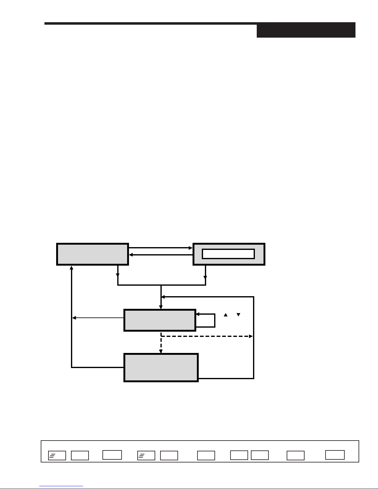
p
CHAPTER 6
TUNING
OVERVIEW
Tuning
The self tune function of the 535 consists of two distinct components — Pretune
and Adaptive Tune. In addition, you may choose from three type of Pretune:
TYPE 1 - for slow thermal processes.
TYPE 2 - for fast fluid or pressure processes.
TYPE 3 - for level control applications.
You choose the type of Pretune in the SELF TUNE menu.
The Pretune and Adaptive Tune components may be used separately or together.
On the following pages is the step by step guide to the TUNING menu paramters.
MANUAL
to place controller
under Manual Control
MENU
MANUAL
OPERATION
DISPLAY
TUNING
FAST + MENU
NOTE:
For more information about Pretune
and Adaptive Tune, refer to section
on Tuning applications in Chapter 7.
Figure 6.1
Access the Tuning Menu Block
DISPLAY
DISPLAY
to return to
o
eration mode
Access Set Up Return to Operation Next menu Next paramet er Next value Access Tuning Return to Operation
+
FAST MENU
535-PROF User's Manual Chapter 6 71
DISPLAY
RECIPE #
*
FAST + MENU
SET UP
(Configuration) Menus
+
FAST MENU
or
to scroll
thru recipes
Set Up Mode
is only accessible if
controller is under
Manual Control.
MENU
▲ ▼
MENU
DISPLAY
Page 81
Tuning
TUNING
SP SELECT
REMOTE SP
ADAPTIVE
DISABLED
PRETUNE
NO
TUNING
1. SP SELECT
Replaces function of the SET PT key. Selects the setpoint used when a recipe
is not running or held.
D REMOTE SP Only if RSP option is installed
• LOCAL SP
• LOCAL SP2 NO. OF SP has to be 2
• LOCAL SP3 NO. OF SP has to be 3
• LOCAL SP4 NO. OF SP has to be 4
• LOCAL SP5 NO. OF SP has to be 5
• LOCAL SP6 NO. OF SP has to be 6
• LOCAL SP7 NO. OF SP has to be 7
• LOCAL SP8 NO. OF SP has to be 8
2. ADAPTIVE
Activates the self tune algorithm (upon transfer to automatic control). Only allowed to operate during soak segments.
D DISABLED
• ENABLED
3. PRETUNE
Activates the pretune algorithm (if unit is under manual control). Not selectable
if a recipe is running or holding
To initiate the Pretune cycle, press the or . Confirm by pressing ACK
within two seconds.
D NO
4. POWR. BACK
POWR. BACK
DISABLED
Reduces setpoint overshoot at power up or after setpoint changes.
D DISABLED
• ENABLED
5. PROP. BND.:1
PROP. BND.:1
50.0
Defines the proportional band for PID set 1.
R 0.1 to 999.0%
D 50.0%
6. RESET:1
RESET:1
20
Access Set Up Return to Operation Next menu Next paramet er Next value Access Tuning Return to Operation
+
FAST MENU
72 Chapter 6 535-PROF User's Manual
DISPLAY
Defines the integral time for PID set 1.
R 1 to 9999 seconds
D 20 seconds
+
FAST MENU
MENU
▲ ▼
MENU
DISPLAY
Page 82
Tuning
7. RATE:1
Defines the derivative time for PID set 1.
R 0 to 600 seconds
D 1 second
8. MAN. RST.:1 (or LOADLINE:1)
Defines the manual reset for PID set 1. If using automatic reset, then this
specifies the load line out value.
R 0 to 100%
D 0%
9. CYCLE TM.:1
Defines the cycle time for control output 1 when using a time proportioning output.
R 0.3 to 120.0 seconds
D 15.0 seconds
10. DEADBAND:1
Defines the dead band for control output 1 when using on/off control.
R 1 to 99999 in engineering units
D 2
11. P. PROP. D.B.
Defines the dead band setting for a slidewire position proportioning output.
R 0.5 to 10.0%
D 2.0%
RATE:1
1
MAN. RST.:1
0
CYCLE TM.:1
15.0
DEADBAND:1
2
P.PROP.D.B.
2.0
12A. PID OFST.:1
For duplex applications, defines the offset for the first output.
R –50.0% to 50.0%
D 0.0%
PID OFST.:1
0
12B. ON OFST.:1
For On/Off applications, defines the offset for the first output.
R -9999 to 99999 in engineering units
D 0
ON/OFST.:1
0
13A. PID OFST.:2
For duplex applications, defines the offset for the second output.
R –50.0% to 50.0%
D 0.0%
PID OFST.:2
0
13B. ON OFST.:2
For On/Off applications, defines the offset for the second output.
R -9999 to 99999 in engineering units
D 0
Access Set Up Return to Operation Next menu Next paramet er Next value Access Tuning Return to Operation
+
FAST MENU
DISPLAY
+
FAST MENU
MENU
▲ ▼
ON/OFST.:2
0
MENU
DISPLAY
535-PROF User's Manual Chapter 6 73
Page 83
Tuning
REL. GAIN:2
1.0
14. REL. GAIN:2
Defines the adjustment factor for the second output’s proportional band. It is
multiplied by the effective gain of output 1 to obtain the second output's proportional band.
R 0.1 to 10.0
D 1.0
CYCLE TM.:2
15.0
DEADBAND:2
2
RSP RATIO
1.00
RSP BIAS
(D)
NO. OF PID
1
15. CYCLE TM.:2
Defines the cycle time for control output 2 when using a time proportioning
output.
R 0.3 to 120.0 seconds.
D 15.0 seconds
16. DEADBAND:2
Defines the dead band for control output 2 when using on/off control.
R 1 to 99999 in engineering units
D 2
17. RSP RATIO
Defines the multiplier applied to the remote set point.
R -99.99 to 99.99
D 1.00
18. RSP BIAS
Defines the bias (additive term) applied to the remote set point.
R Any value in engineering units (minimum is BIAS LOW; maximum is
BI AS HIGH)
D Dependent on the BIAS LOW and BIAS HIGH values
19. NO. OF PID
Defines the number of PID sets that will be stored and available for use.
R 1 to 8 For numbers>1, PID TRIP defines tripping be-
tween the PID sets
D 1
• SP NUMBER PID Set = current local setpoint (specified in
NO. OF SP). Each PID set has a respective
SP NUMBER.
• REC.NUMBER PID Set = current recipe #. If no recipe is running or held, previous PID set is used.
• SEG.SELECT PID Set = set assigned to the current recipe
segment. If no recipe is running or held, previous PID set is used.
• PV NUMBER PID Set = process variable (PV1 or PV2) used
when PV SOURCE = 1/2: SWITCH or PV
SOURCE = 1/2:BACKUP
D 1
Access Set Up Return to Operation Next menu Next paramet er Next value Access Tuning Return to Operation
+
FAST MENU
74 Chapter 6 535-PROF User's Manual
DISPLAY
FAST MENU
+
MENU
▲ ▼
MENU
DISPLAY
Page 84
Tuning
20. PID TRIP
For NO. OF PID > 1, defines the variable used to select the various PID sets.
Not applicable for SP NUMBER, REC. NUMBER or SEG. SELECT.
• PV VALUE PID set selection based on process variable
D SP VALUE PID set selection based on setpoint
• DEV. VALUE PID set selection based on deviation from
setpoint
21. TRIP:1
Defines the value that triggers a change to the primary set (#1) of PID values.
R The process variable range
D Dependent on the process variable range
For each set of PID 2 through 8 (or equals SP NUMBER, REC.NUMBER
or SEG.SELECT) set up the following group of parameters (X represents the
PID set number), as they appear for each set of PID. The controller designates the values for the active PID parameter in the third display with this
symbol—*—on either side.
22. PROP. BND.:X
Defines the proportional band for PID set X.
R 0.1 to 999.0%
D 50.0%
PID TRIP
SP VALUE
TRIP:1
(D)
PROP.BND.:X
(D)
23. RESET:X
Defines the integral time for PID set X.
R 1 to 9999 seconds (increments of 1)
D 20 seconds
24. RATE:X
Defines the derivative time for PID set X.
R 0 to 600 seconds
D 1 seconds
25. MAN. RST.:X (or LOADLINE:X)
Defines the manual reset (or load line) for PID set X.
R 0 to 100%
D 0%
26. TRIP:X
This defines the value that triggers a change to the Xth set of PID values.
R The process variable range
D Dependent on the process variable range
RESET:X
(D)
RATE:X
1
MAN.RST.:X
0
TRIP:X
(D)
Access Set Up Return to Operation Next menu Next paramet er Next value Access Tuning Return to Operation
+
FAST MENU
535-PROF User's Manual Chapter 6 75
DISPLAY
+
FAST MENU
MENU
▲ ▼
MENU
DISPLAY
Page 85

Tuning
TUNING
Parameter Definition Values
1. SP SELECT Selects the setpoint used when a recipe is not running or held
2. ADAPTIVE Activates the self tune algorithm
3. PRETUNE Activates the pretune algorithm
4. POWR. BACK Reduces setpoint overshoot at power up or after setpoint changes
5. PROP. BND.:1 Proportional band for PID set 1
6. RESET:1 Integral time for PID set 1
7. RATE:1 Derivative time for PID set 1
8. MAN. RST.:1 Manual reset for PID set 1.
9. CYCLE TM.:1 Cycle time for control output 1 for time proportioning output
10. DEADBAND:1 Dead band for control output 1 for on/off control
11.P. PROP. D.B. Dead band setting for slidewire position proportioning output
12A. PID OFST.:1 Offset for the first output for duplex applications
12B. ON OFST.:1 Offset for first output for on/off applications
13A. PID OFST.:2 Offset for the second output for duplex applications
13B. ON OFST.:2 Offset for second output for on/off applications
14. REL. GAIN:2 Adjustment factor for the second output’s proportional band
15. CYCLE TM.:2 Cycle time for control output 2 for time proportioning output
16. DEADBAND:2 Dead band for control output 2 for on/off control
17. RSP RATIO Multiplier for remote set point
18. RSP BIAS Bias for remote set point
19. NO. OF PID Number of PID sets
20.PID TRIP For NO. OF PID > 1, variable used to select the various PID sets
21. TRIP:1 Value that triggers a change to the primary set (#1) of PID values
22. PROP. BND.:2 Proportional band for PID set 2
23. RESET:2 Integral time for PID set 2
24. RATE:2 Derivative time for PID set 2
25. MAN. RST.:2 Manual reset (or load line) for PID set 2
26. TRIP:2 Value that triggers a change to the 2nd set of PID values
27. PROP. BND.:3 Proportional band for PID set 3
76 Chapter 6 POWERS 535-PROF User's Manual
Page 86

28.RESET:3 Integral time for PID set 3
29. RATE:3 Derivative time for PID set 3
30.MAN. RST.:3 Manual reset (or load line) for PID set 3
31. TRIP:3 Value that triggers a change to the 3rdset of PID values
32. PROP. BND.:4 Proportional band for PID set 4
33.RESET:4 Integral time for PID set 4
34. RATE:4 Derivative time for PID set 4
35.MAN. RST.:4 Manual reset (or load line) for PID set 4
36. TRIP:4 Value that triggers a change to the 4th set of PID values
37. PROP. BND.:5 Proportional band for PID set 5
38.RESET:5 Integral time for PID set 5
39. RATE:5 Derivative time for PID set 5
Tuning
40.MAN. RST.:5 Manual reset (or load line) for PID set 5
41. TRIP:5 Value that triggers a change to the 5th set of PID values
42. PROP. BND.:6 Proportional band for PID set 6
43.RESET:6 Integral time for PID set 6
44. RATE:6 Derivative time for PID set 6
45.MAN. RST.:6 Manual reset (or load line) for PID set 6
46. TRIP:6 Value that triggers a change to the 6th set of PID values
47. PROP. BND.:7 Proportional band for PID set 7
48.RESET:7 Integral time for PID set 7
49. RATE:7 Derivative time for PID set 7
50.MAN. RST.:7 Manual reset (or load line) for PID set 7
51. TRIP:7 Value that triggers a change to the 7th set of PID values
52. PROP. BND.:8 Proportional band for PID set 8
53.RESET:8 Integral time for PID set 8
54. RATE:8 Derivative time for PID set 8
55.MAN. RST.:8 Manual reset (or load line) for PID set 8
56. TRIP:8 Value that triggers a change to the 8th set of PID values
POWERS 535-PROF User's Manual Chapter 6 77
Page 87
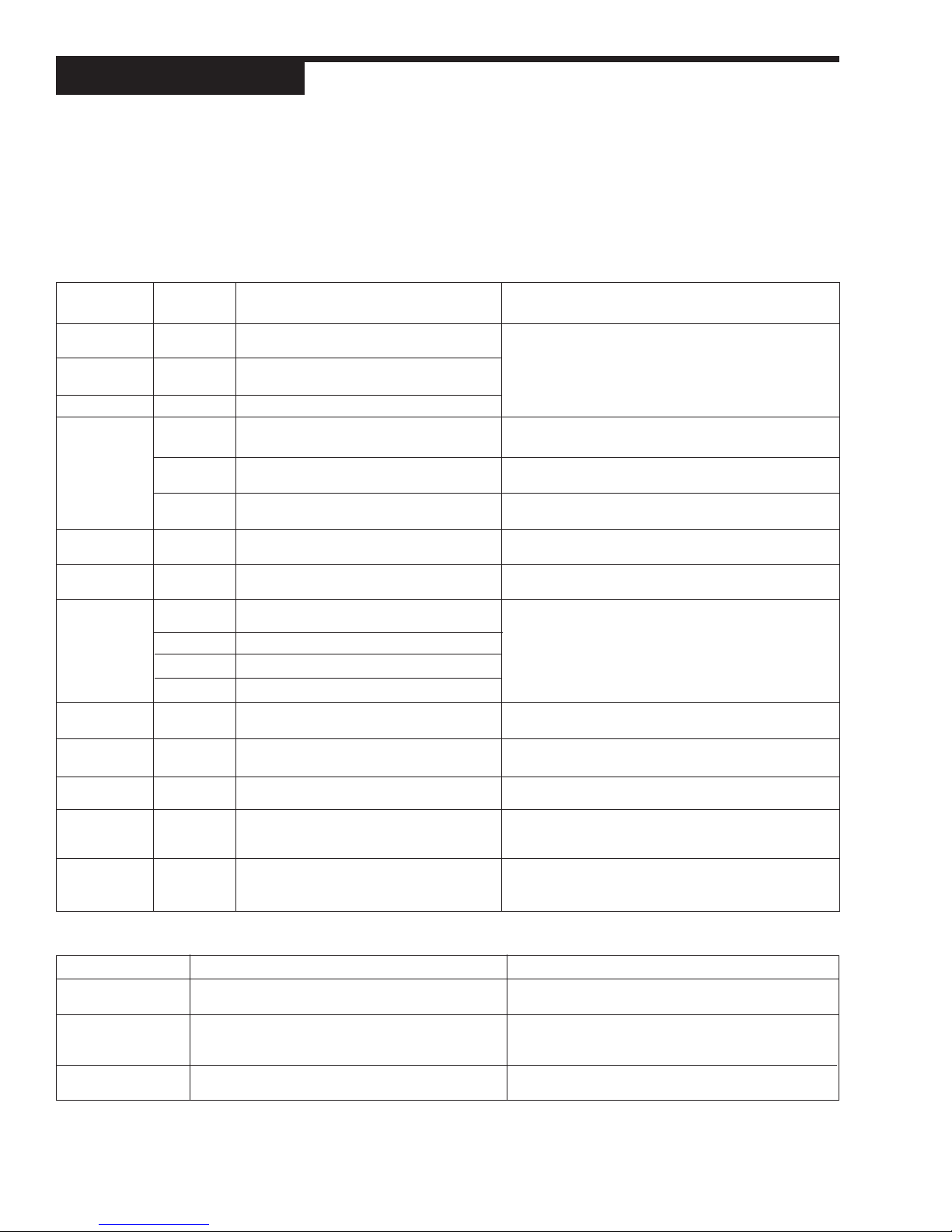
Tuning
SELF TUNE MESSAGES AND TROUBLESHOOTING
Refer to Chapter 7 for more information on the Self Tune function of the 535 controller.
When the Pretune function terminates, one of the following messages will appear:
Message
COMPLETED
ABORTED
LIMIT ERR.
TIMEOUT
NOISE ERR.
INPUT ERR.
OUT. ERROR
DATA ERR.
ZERO ERR.
DEV. ERROR
RETRY
Pretune
Type
1
2,3
1,2,3
1
2,3
1,2,3
1,2,3
1,2,3
1,2,3
1,2,3
1,2,3
1,2,3
1,2,3
2,3
2,3
1
1,2,3
Conclusion/Problem
PRETUNE has generated initial PID and the
Dead Time values
PRETUNE had generated initial PID, Response
Time, Band Noise and the Dead Time values
User has aborted PRETUNE before completion
The Process variable went beyond the HI
LIMIT or LOW LIMIT
The Process variable went beyond the HI
LIMIT or LOW LIMIT
The inital process variable was near or beyond
the HI LIMIT or LOW LIMIT
TIMEOUT limit was reached before Pretune
completed
Too much PV noise was detected
PV or Cold Junction break detected during
Pretune
PV HIGH or PV LOW detected during Pretune
SLIDEWIRE break detected during Pretune
Remote SP Break detected during Pretune
The initial control output is outside the high and
low limits defined in the Control menu
The PV moved too quickly to be analyzed
One or more model parameters are calculated
to be zero
The initial PV is too close to the TUNE PT.
The Process variable went beyond the HI
LIMIT or LOW LIMIT
Corrective Action
Change the HI LIMIT and LOW LIMIT, or the HIGH
OUT and LOW OUT, and run Pretune again
Change the HI LIMIT and LOW LIMIT, or the
OUT.STEP size and run Pretune again
Change the manual output percentage, or the HI
LIMIT and LOW LIMIT, and run Pretune again
Set a longer TIMEOUT period and/or increase the
OUT.STEP size, and run Pretune again.
Eliminate the noise source (if possible) or increase
the OUT.STEP and run Pretune again
Check the described conditions and make
corrections or repairs
Change the manual output percent and run Pretune
again
Decrease the OUT.STEP size and run Pretune
again
Increase the OUT.STEP size and run Pretune again
Move TUNE PT. (or the Setpoint if TUNE PT. is
Automatic) farther from the process variable and run
Pretune again
Check if any PID values were generated and if they
are acceptable. If not, eliminate noise sources (if
possible) and run Pretune again
If Pretune and Adaptive Tune do not generate optimal PID values for control, check the following menu entries:
Message
RESPONSE TIME
NOISE BAND
PRETUNE
Potential Problem
Adaptive Tune cannot run if RESPONSE TIME is
inaccurate
Adaptive Tune cannot compensate for PV oscillation
due to hysteresis of output device (e.g., a sticky valve)
Pretune does not develop optimum PID Parameters
78 Chapter 6 POWERS 535-PROF User's Manual
Corrective Action
Run TYPE 2 or TYPE 3 Pretune to obtain the correct value,
or enter it manually
Set NOISE BAND large enought to prevent Adaptive Tune
from acting on the oscillation. If oscillation is not acceptable,
consider replacing valve
Wrong pretune TYPE selected. Refer to Chapter 7, the
section on Self Tune
Page 88

CHAPTER 7
APPLICATIONS
The 535 controller provides a variety of user-programmable control features and
capabilities. The following topics are included in this chapter:
Applications
NOTE: Controller capabilities depend
upon the specified hardware option.
A. Profile Control ................................................. 79
B. Control Type ................................................... 85
C. Alarm s ............................................................. 86
D. Duplex Control ................................................ 90
E. Slidewire Position Proportioning Control ..... 95
F. Veloc ity Po sition Proportioning Control ...... 9 6
G. Staged Outputs .............................................. 97
H. Retransmission .............................................. 97
I. Digital Inputs .................................................. 98
J. Remote Setpoint ........................................... 100
K. Multiple Setpoints ........................................ 101
L. Multiple Sets of PID Values ........................ 101
M. Powerback .................................................... 102
®
N. Self Tune—POWERTUNE
O. Ramp-to-Setpoint ......................................... 109
P. Input Linearization ....................................... 109
.............................
103
A. PROFILE CONTROL
The 535-PROF controller is capable of storing 20 separate recipes. Each recipe
can consist of up to 12 ramps and 12 dwells. Individual recipes may be continuously run or be repeated up to 99 times. Recipes may be linked together to form
longer, more complex recipes. Some profile control terms are:
Ramp
A rise or fall of the setpoint in a given segment. Ramps may be defined by the
time it will take for the setpoint to be achieved or the rate of rise or fall necessary
for the target (soak) setpoint to be achieved.
Dwell or Soak
The designated period of time in which the setpoint does not change after the
ramp has been completed.
Guaranteed Soak
Guaranteed soak insures that the soak setpoint has been achieved before
the soak segment starts.
Example: Ramp 1 is programmed for 2 hours. The Soak setpoint is 400° and
the soak time is set for 4 hours. If 400° can not be achieved in the 2 hour ramp
time, the timing of the soak will not start until the setpoint has been reached.
To use this feature,two parameters must be defined. The first one,
GUAR.SOAK, defines whether guaranteed soak is used and how it is used. It is
located in the REC.CONF. menu. The second parameter, SOAK HYST., is
located in the RECIPE # menu. It defines the absolute value of the maximum
allowable deviation from setpoint when a soak segment starts. If the deviation
exceeds this value, guaranteed soak will stop the clock until the deviation is less
than the soak hysteresis. Then the soak segment will begin. In addition, if the
deviation exceeds the soak hysteresis value during the soak segment, the soak
timing will stop until the deviation is less than the soak hysteresis value.
Cycles
Recipes may be repeated up to 99 times before completion or being linked to
a different recipe. Recipes may also be set up to run continuously.
Q. Load Line ....................................................... 111
R. Security ......................................................... 111
S. Reset Inhibition ............................................ 112
T. Process Variable Reading Correction ........ 112
U. Serial Communications ................................ 113
V. Cascade Control ........................................... 114
W. Ratio Contro l ................................................. 117
NOTE:
Self Tune and Adaptive Tune may be
used to optimize PID settings at
varous PV/LOAD points, but should
NOT be used while running a recipe.
Consult factory for further details.
535-PROF User's Manual Chapter 7 79
Page 89

Applications
Linking
Recipes may be linked together to form longer, more complicated programs.
Through the selective use of CYCLES and LINKING, complex recipes with
subroutines can be created.
Events
For each ramp and dwell, 1, 2 or 3 available relays may be opened or closed.
These may be used for a variety of purposes to include starting and stopping
other process equipment. Upon recipe completion, events may be held until
released by the operator (using FAST + ACK).
Programming recipes requires the user to make selections in the REC.
CONF. menu of the SET UP mode before programming the actual recipes.
Software Configuration
The controller must be configured for the profile option before
accepting recipes:
1. Enter the SET UP mode. Select the REC. CONF. menu.
2. The first parameter is RECIPES. This parameter defines the number of
recipes available in the 535. Choices are:
D 1
R 1 through 20
3. The next parameter is TIME BASE. It defines whether recipes are timed in
hours and minutes or in minutes and seconds. Choices are:
D HOURS:MIN
• MIN:SEC.
4. The next parameter is RAMP UNIT. It defines the times unit for ramp segments (hours:min or min:sec) or rate of change required to reach setpoint. If
TIME BASE=HOURS:MIN, the ramp unit will be in PV units per minute. If TIME
BASE=MIN:SEC the ramp unit will be in PV units per second. Choices are:
D TIME
• RATE
5. The next parameter is SP START. It selects whether the first ramp
segment’s setpoint must start at the IDLE setpoint or if it can be adjusted to
account for the initial PV value (thus allowing the ramp segment to be shortened). Choices are:
• IDLE SP the IDLE SP will be the starting setpoint of the first ramp
segment
• PV the first ramp’s starting setpoint can be adjusted
6. The next parameter is GUAR.SOAK. It selects whether the guaranteed soak
feature will be used. Its choices are:
D OFF guaranteed soak will not occur
• START SEG. guaranteed soak can occur only at the start of a soak segment
• WHOLE SEG. guaranteed soak can occur at the start of or at anytime during
soak segment
7. The next 3 parameters are EVT.:1 OUT, EVT.:2 OUT and EVT.:3 OUT.
These select which outputs are assigned to each events. Choices are:
D NONE
•2
•3
80 Chapter 7 535-PROF User's Manual
Page 90

•4
The numerical choices only appear if the corresponding output is config-
ured as ALM.EVT:ON or ALM.EVT:OFF in the CONFIG. menu.
8. The next parameter is HOLD EVT. It determines whether the last
segment’s event(s) will be held active after the recipe has successfully
completed. Choices are:
D DISABLE
• ENABLE
Now the recipes can be programmed:
1. Enter the RECIPE SET UP mode. The display will indicate RECIPE #
(# =recipe number) in the 2nd line.
Use and to select the recipe to be programmed.
Use MENU to advance through the parameters.
2. The first parameter is CYCLES. It selects the number of times the recipe
will run before ending or going to the next linked recipe. Choices are:
• CONTINUAL
D 1
R 1 - 99
3. The next parameter is NEXT LINK. It defines which recipe will run next
after the current recipe has completed. Choices are:
D NONE
R 1 to # of configured recipes
• NO OUTPUT
4. The next parameter is IDLE SP. It defines the setpoint to be used when
the recipe starts or after it has completed. Choices are:
D LAST SP use the previous setpoint [default]
R -9999 to 99999
• REMOTE SP use the remote setpoint (only if option installed an enabled)
The decimal point is defined by the DECIMAL parameter.
5. The next parameter is SOAK HYST. It defines the absolute value of the
maximum allowable deviation from the setpoint when a soak segment starts. If
the deviation exceeds this value, Guaranteed Soak will occur.
This parameter appears only if GUAR.SOAK is not OFF. Choices are:
D OFF
R 1 to 99999
The decimal point is defined by the DECIMAL parameter in the PV1
INPUT menu
6. The next parameter is RAMP RT:## (## = 1 to 12). It defines the rate of
rise or fall of the setpoint during ramp segment ## while approaching soak
setpoint ##. This parameter will only appear if RAMP UNIT = RATE. Choices
are:
D OFF ends recipe progrmming
R 1 to 99999/MIN if TIME BASE = HOURS:MIN
R 1 to 99999/SEC. if TIME BASE = MIN:SEC
Applications
535-PROF User's Manual Chapter 7 81
Page 91

Applications
The decimal point is defined by the DECIMAL parameter.
7. The next parameter is RAMP TM:## (## = 1 to 12). It defines the time for
the current ramp segment (##) to reach the current soak setpoint (##). This
parameter will only appear if RAMP UNIT = TIME. Choices are:
D OFF ends recipe programming
R 00:01 to 99:59 HR:MN if TIME BASE = HOURS:MIN
R 00:01 to 99:59 MN:SC if TIME BASE = MIN:SEC
IMPORTANT: For each RAMP segment, you will scroll through and set
values for the next six parameters. However, choosing OFF for either RAMP
RT.## or RAMP TM## will conclude the programming.
8. The next parameter is RAMP EV:## (## = 1 to 12). It selects which events
will be activated during the current ramp segment. Choices are:
D NONE
• EVENT 1 event output 1 is selected
• EVENT 2 event output 2 is selected
• EVENT 12 event outputs 1 and 2 are selected
• EVENT 3 event output 3 is selected
• EVENT 13 event outputs 1 and 3 are selected
• EVENT 23 event outputs 2 and 3 are selected
• EVENT 123 event outputs 1, 2 and 3 are selected
9. The next parameter is SOAK SP:## (## = 1 to 12). It defines the setpoint
after the current ramp segment (##) has completed. Choices are:
• -9999 to 99999
R Dependent upon process variable range
The decimal point defined by the DECIMAL parameter
10. The next parameter is SOAK TM:## (## = 1 to 12). It defines the length
of the current soak segment. Time units are defined by the TIME BASE
parameter in the REC. CONF. menu. Choices are:
D OFF Selecting off eliminates the SOAK and makes possible 2 or more
ramps to different setpoints.
R 00:01 to 99:59 HR:MN if TIME BASE = HOURS:MIN
R 00:01 to 99:59 MN:SC if TIME BASE = MIN:SEC
11. The next parameter is SOAK EV:## (## =1 to 12). It defines which
events will be activated during this soak segment. This parameter will only
appear if SOAK TM:## is not OFF. Choices are:
D NONE
• EVENT 1 event output 1 is selected
• EVENT 2 event output 2 is selected
• EVENT 12 event outputs 1 and 2 are selected
• EVENT 3 event output 3 is selected
• EVENT 13 event outputs 1 and 3 are selected
• EVENT 23 event outputs 2 and 3 are selected
• EVENT 123 event outputs 1, 2 and 3 are selected
12. The last parameter is PID SET:## (## =1 to 12). It selects which PID
set to use during the current ramp and soak segments. This parameter only
appears if NO. OF PID = SEG SELECT (in the TUNING menu). Choices are:
D LAST SET
82 Chapter 7 535-PROF User's Manual
Page 92

Applications
Use this chart to set up your recipe(s).
RAMP TIME
SOAK TIME
SOAK HYS.
EVENT 1
EVENT 2
EVENT 3
PID SET
RATE
END SETPOINT
1
1
2
2
3
3
4
4
5
5
Ramp
Soak
Ramp
Soak
Ramp
Soak
Ramp
Soak
Ramp
Soak
RECIPE #: Start From Time Base
PROCESS
T I M E
Idle Setpoint: Process Variable HRS/MIN: MIN/SEC:
PROFILE CONTROLLER SET-UP WORKSHEET
Ramp
6
Soak
6
Ramp
7
Soak
7
Ramp
8
Soak
8
Ramp
9
Soak
9
Ramp
10
Soak
10
Ramp
11
Soak
11
Ramp
12
535-PROF User's Manual Chapter 7 83
Soak
12
Page 93

Applications
Figure 7.1
Contacts for Recipe Selection
ber
Recipe Num
None
1
2
3
4
5
6
7
O = Open
● = Closed
NOTE:
The 535 Profile Controller can store
20 recipes, but only recipes 1 through
7 may be selected remotely. This will
use three of the five input contacts.
The two remaining can be used to
start or abort a recipe (START REC.)
or hold the recipe (HOLD REC.). See
Section I for other input options.
Contact 1
O
●
O
●
O
●
O
●
Contact 2
O
O
●
●
O
O
●
●
Contact 3
O
O
O
O
●
●
●
●
R 1 to 8
13. After parameter PID SET, the controller will cycle to the RAMP RT:## or
RAMP TM:## parameter.
To end programming:
• Set either RAMP RT:## = OFF or RAMP TM:## = OFF.
To continue programming:
• Set a value for for RAMP RT:## or RAMP TM:##, and scroll
through subsequent parameters.
Digital Inputs
Special digital input capabilities are available for 535 as a Profile Controller
(see Section I in this chapter for information on standard Digital Input
options). Profile Control digital input options are:
• RECIPE. 1-7
Selects recipe number (1through 7 using binary contacts 1, 2 and 3) for
the next time a recipe is run. The recipe number selected must be be
tween 1 and the number of recipes selected in the REC. CONF. menu.
Note that a binary value of “0” (zero) is inactive, and values of 1 to 7 select
recipes 1 to 7 respectively.
• START REC. (Active = Start Recipe; Inactive = Abort Recipe)
When activated, the most recently selected recipe will start running.
When deactivated, a running or held recipe will be aborted. This action
will take place if a recipe is not running or held at the time of the contact
closure.
• HOLD REC. (Active = Hold Recipe; Inactive = Resume Recipe)
When activated, a running recipe will be held at its current position.
When deactivated, a held recipe will resume running from its current
position.
• RESET REC.
When activated, a running or held recipe is reset to the beginning. If the
recipe is linked to other recipes, the beginning of the first linked recipe
will be used. When deactivated, no action will be taken.
• ABORT REC.
When activated, a running or held recipe will be aborted. When deacti
vated, no action will be taken.
• NEXT SEG.
When activated, a running or held recipe will advance to the end of the
current segment. When deactivated, no action will be taken.
• PV2. SWITCH
(only applicable if PV SOURCE = 1/2:SWITCH). When activated, causes
the controller to use PV2 as the PV input (instead of PV1).
84 Chapter 7 535-PROF User's Manual
Master/Slave Operation
The 535 Controller with profile option Is capable of operating as a master
setpoint generator controlling up to 4 standard (slave) 535 controllers. The
535 with profile option can retransmit the recipe setpoints to the remote
setpoint inputs of up to 4 standard 535 controllers. Configured as such, a
common recipe may be applied to 5 different control loops or heating/cooling
zones.
Page 94

Hardware Configuration
• The 535 controller with profile option must be configured with an analog
milliamp module in the first available output.
• See Section H in this chapter for instructions on configuring the retrans-
mission feature.
• Up to four model 535 controllers can be used, each must be specified with
the remote setpoint option.
• See Section J in this chapter for instructions on configuring the optional
remote setpoint feature.
Applications
B. CONTROL TYPE
Software Configuration
1. Go to the CONTROL menu.
2. For the parameter ALGORITHM, select the type of 535 control:
• ON-OFF
“Crude” control similar to a household thermostat. Used primarily on
slow, stable processes where moderate deviation (cycling) around
setpoint is tolerable. Only available with SSR, SSR Drive, and relay
outputs.
• P
Proportional only control. Provides much better control than on/off. Used
on processes that are less stable or require tighter control, but have few
load variations and do not require a wide range of setpoints.
• PI
Proportional plus integral control. In addition to proportional control, it
compensates for control errors due to wide range of setpoints or load
requirements. The integral term works to eliminate offsets.
• PD
Proportional plus derivative control. In addition to proportional control,
it compensates for control errors due to fast load variations.
• PID
Proportional plus integral plus derivative control. In addition to
proportional control, it compensates for changes in setpoint, load
requirements and process variations.
• PID/ON-OFF
Only available with Duplex control. First output uses the PID algorithm,
while second output uses on/off control.
3. For algorithms using the derivative function (D), choose the conditions for
the derivative term:
Scroll to parameter D. SOURCE
• For derivative action based on error, or deviation from setpoint, choose
DEVIATION
• For derivative action based on changes in the process variable, choose
PV.
NOTE: Controller capabilities depend
upon the specified hardware option.
535-PROF User's Manual Chapter 7 85
Page 95

Applications
NOTE: Specifying a variable other
than the setpoint (SP) to HIGH
ALARM and LOW ALARM allows for
greater flexibility in creating alarm
and control strategies.
C. ALARMS
The 535 controller has two extremely flexible and powerful software alarms. The
number of available outputs limits how alarms are linked to relays. A Global
Alarm feature allows all alarms to be assigned to the same relay.
The 535 indicates an alarm condition by:
• Lighting up the alarm icon(s)
• Displaying a custom message in the 3rd display
• Illuminating the ACK key (if the alarm is acknowledgeable)
Software Configuration
1. Access the ALARM menu.
2. Set values for the following parameters. All possible values are shown.
ALM.TYPE:1 and ALM. TYPE:2
Specifies the type of alarm to implement. Selection includes:
• HIGH ALARM
High process variable alarm. Occurs when the process variable exceeds the alarm setpoint.
• LOW ALARM
Low process variable alarm. Occurs when the process variable goes
below the alarm setpoint.
• HIGH/LOW
Combination of high and low alarms. Occurs when the process variable exceeds the individually set high or low setpoint.
• BAND
Creates a band centered around the control setpoint, that is twice
the alarm setpoint. Alarm occurs when the process variable travels
outside of this band. The alarm is dependent on the control setpoint.
As the control setpoint changes, the band adjusts accordingly.
For example, if the control setpoint is 500 and the alarm setpoint is
25, then the band extends from 475 to 525.
• DEVIATION
Similar to the band alarm but creates a band only on one side of the
control setpoint. Alarm occurs when the process variable deviates
from the control setpoint by an amount greater than the alarm setpoint.
This alarm is dependent on the control setpoint; as the control setpoint
changes, the alarm point changes.
For example, if the control setpoint is 500 and the alarm setpoint is
+50, then an alarm occurs when the process variable exceeds 550.
In order for an alarm to occur when the process variable drops below
450, select an alarm setpoint of –50.
• MANUAL
Alarm occurs when the controller is put into manual mode of operation. This may be useful for security purposes or to alert the operator
that 535 is no longer under automatic control.
86 Chapter 7 535-PROF User's Manual
Page 96

• RATE
Alarm occurs when the process variable changes at a rate greater
than what is specified by the alarm setpoint and time base. This alarm
helps to anticipate problems before the process variable can reach
an undesirable level.
For example, if the alarm setpoint is 10 with a time base of 5 seconds, an alarm occurs whenever a change in process variable greater
than 10 occurs in 5 seconds.
ALM.SRC.:1 and ALM.SRC.:2
For HIGH , LOW or HIGH/LOW alarms, specifies the variable (source)
upon which a selected alarm is based. Selection includes:
•PV
• PV2
•SP
• RAMP SP
• DEVIATION
• OUTPUT
Applications
ALARM SP:1 and ALARM SP:2
Defines the point at which an alarm occurs. For a RATE (rate of change)
alarm, it specifies the amount of change (per RATE TIME period) that
must occur before the alarm activates. A negative value specifies a negative rate-of-change. Does not apply to HIGH/LOW alarms.
HIGH SP:1 and HIGH SP:2
For a HIGH/LOW alarm, defines the high setpoint at which an alarm occurs.
LOW SP:1 and LOW SP:2
For a HIGH/LOW alarm, defines the low setpoint at which an alarm occurs.
DEADBAND:1 and DEADBAND:2
Specifies the range through which the process variable must travel before leaving an alarm condition (see alarm examples at the end of this
section). Prevents frequent alarm oscillation or “chattering” if the process
variable has stabilized around the alarm point.
ALM.1 OUT and ALM.2 OUT
For any enabled alarm, selects the output number to which the selected
alarm will be assigned. It is possible to assign both alarms to the same
output relay, thus creating a “global” alarm .
LATCHING:1 and LATCHING:2
A latching (YES) alarm will remain active after leaving the alarm condition unless it is acknowledged. A non-latching (NO) alarm will return to
the non-alarm state when leaving the alarm condition without being acknowledged.
535-PROF User's Manual Chapter 7 87
Page 97

Applications
Alarm Parameters Reference
For Alarm 1
Parameter Description
ALM. TYPE:1 Type
ALM. SRC.:1 Source
ALARM SP:1 Setpoint
HIGH SP:1 High setpoint
LOW SP:1 Low setpoint
DEADBAND:1 Deadband
ALM.:1 OUT. Output number
LATCHING:1 Latching sequence
ACK.:1 Acknowledging
POWER UP:1 Status on power up
MESSAGE:1 Message
For Alarm 2
Parameter Description
ALM. TYPE:2 Type
ALM. SRC.:2 Source
ALARM SP:2 Setpoint
HIGH SP:2 High setpoint
LOW SP:2 Low setpoint
DEADBAND:2 Deadband
ALM.:2 OUT. Output number
LATCHING:2 Latching sequence
ACK.:2 Acknowledging
POWER UP:2 Status on power up
MESSAGE:2 Message
For either alarm
(depending on choices)
Parameter Description
FAULT Fault assignment
OUTPUT Output action for rate
RATE TIME Tim e base for rate
ACK.:1 and ACK.:2
For any enabled alarm, enables or disables operator use of the ACK key
to acknowledge an alarm at any time, even if the control process is still
in the alarm condition.
A latching alarm can always be acknowledged when it is out of the alarm
condition. When either alarm is available to be acknowledged, the ACK
key will be illuminated. If both alarms are acknowledgeable, pressing ACK
will first acknowledge alarm #1. Pressing ACK a second time will acknowledge alarm #2.
POWER UP:1 and POWER UP:2
For any enabled alarm, selects the alarm condition upon power up.
Choices are:
• NORMAL
Controller will power up in alarm only if it is in alarm condition.
• ALARM:
Controller always powers up in alarm regardless of system’s alarm
condition. This is an excellent way to activate an alarm if there has
been a power failure.
• DELAYED
Controller will never power up in alarm, regardless of system’s alarm
condition. The system must leave and reenter the alarm condition
before the alarm will activate. This is typically used to avoid alarms
during start up.
MESSAGE:1 and MESSAGE:2
Allows user to specify a nine-character message to be displayed when
the respective alarm is active. If both alarms are active or any other diagnostic message is present, the messages will alternate.
FAULT
Activates an alarm if the process variable signal is lost. Assign this function to either Alarm 1 or Alarm 2 (not both). This action is in addition the
selected alarm type (additive alarm function).
88 Chapter 7 535-PROF User's Manual
OUTPUT
For a RATE alarm, selects the output action. Use to obtain early indication of a possible break in the process variable signal. Select PV BREAK
to have rate-of-change alarm take the same action as a detection of a
break in the process variable signal (where it trips to manual control at a
predetermined output).
RATE TIME
For RATE alarms, defines the time period over which a discrete change
in process variable must occur for the rate alarm to be activated. The
amount of change is defined by the alarm setpoint. The rate-of-change
is defined as the amount of change divided by the time period.
Example
A. If the alarm setpoint is set to 10 and the time base is set to 1 second,
the rate of change is 10 units per second.
Page 98
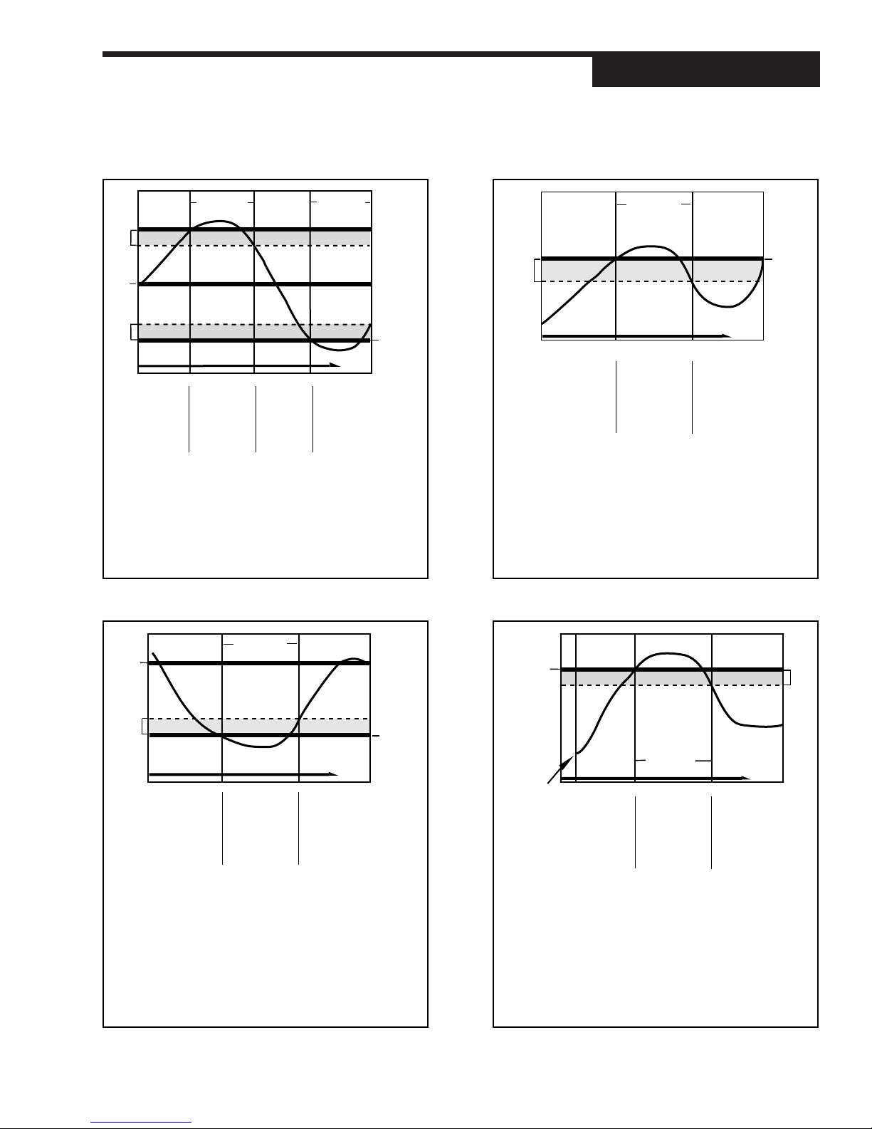
TIME
ICON OFF
NO ALARM
IN ALARM
CONDITION
MAY
ACKNOWLEDGE
RELAY
ENERGIZED
RELAY
DE-ENERGIZED
ICON ON
RELAY
DE-ENERGIZED
ICON OFF
NO ALARM
PV
DB
A.SP
PARAMETER SETTINGS:
OUTPUT N = ALM.RLY:ON (N = 2 to 4)
ALM. TYPE:1 = HIGH ALRM.
ALM.:1 OUT. = N (N = 2 to 4)
LATCHING = NO LATCH
ACK.:1 = ENABLED
TIME
ALARM
CONDITION
RELAY
ENERGIZED
RELAY
ENERGIZED
ICON ON
PV
A.SP
UNIT
POWER UP
RELAY
ENERGIZED
ICON ON
DB
MAY
ACKNOWLEDGE
ICON ON
MAY
ACKNOWLEDGE
CANNOT
ACKNOWLEDGE
PARAMETER SETTINGS:
OUTPUT N = ALM.RLY:ON (N = 2 to 4)
ALM. TYPE:1 = HIGH ALM.
ALM.:1 OUT. = N (N = 2 to 4)
LATCHING:1 = LATCH
ACK.:1 = DISABLED
POWER UP:1 = ALARM
PARAMETER SETTINGS:
OUTPUT N = ALM.RLY:ON (N = 2 to 4)
ALM. TYPE:1 = DEVIATION
ALM.:1 OUT. = N (N = 2 to 4)
LATCHING = LATCH
ACK.:1 = ENABLED
ALARM SP:1 = (<0)
TIME
IN ALARM
CONDITION
MAY
ACKNOWLEDGE
RELAY
ENERGIZED
RELAY
DE-ENERGIZED
ICON ON
MUST
ACKNOWLEDGE
TO SHUT OFF
ICON AND
DE-ENERGIZE
RELAY
ICON OFF
NO ALARM
PV
C.SP
+ A.SP
DB
C.SP
TIME
ICON ON
IN ALARM
CONDITION
CANNOT
ACKNOWLEDGE
RELAY
DE-ENERGIZED
RELAY
ENERGIZED
ICON ON
RELAY
DE-ENERGIZED
ICON OFF
PV
ICON OFF
RELAY
ENERGIZED
NO ALARM
NO ALARM CANNOT
ACKNOWLEDGE
C.SP
+ A.SP
C.SP
DB
C.SP
- A.SP
DB
IN ALARM
CONDITION
PARAMETER SETTINGS:
OUTPUT N = ALM.RLY:OFF (N = 2 to 4)
ALM. TYPE:1 = BAND
ALM.:1 OUT. = N (N= 2 to 4)
LATCHING = NO LATCH
ACK.:1 = DISABLED
BAND ALARM HIGH PROCESS VARIABLE ALARM
DEVIATION ALARM POWER UP ALARM
Applications
Figure 7.2 Alarm Examples
535-PROF User's Manual Chapter 7 89
Page 99

Applications
NOTE: The duplex output states vary
depending upon:
1. Control Type (PID, On/Off, etc.)
2. Control Action (DA, RA)
3. Output Limits
4. Output Gap or Overlay, and
5. Ouput 2 Relative Gain and PID%
Output.
Please refer to the output state
examples in this section to confirm
that the configuration is appropriate
for the process.
NOTE: Set manual reset/load line
parameters to 50% when using
Duplex control (MAN. RST.:X
parameter is in the TUNING menu.)
B. If the alarm setpoint is set to 100 and the time base set to 10, the rate
of change is also 10 units per second.
In example A, the process variable would only have to experience a ten
unit change over a short period of time, while in Example B, it would require a 100 unit change over a ten second period. Example A is much
more sensitive than Example B. In general, for a given rate-of-change,
the shorter the time period, the more sensitive the rate alarm.
D. DUPLEX CONTROL
The Duplex control algorithm enables two discrete control outputs for the control
loop. Duplex control is commonly used for applications that require both heating
and cooling or when 2 control elements are needed to achieve the desired result.
Hardware Configuration
• The controller must have two output modules assigned to the loop (any
combination of output modules).
Software Configuration
1. Go to the CONFIG. menu.
Set CTRL.TYPE to DUPLEX.
2. To use different algorithms for each output (PID for the first, and On/Off for
the second):
Go to the CONTROL menu.
Set ALGORITHM to PID:ON/OFF.
3. To make the control action for each output independent of the other:
Go to the CONTROL menu.
Set ACTION:1 or ACTION:2 to either DIRECT or REVERSE action based
on the diagrams in the output examples section (
4. Go to the TUNING menu.
Set values for PID OFST:1 (or ON OFST:1) and PID OFST:2 (or ON OFST:2).
These parameters allow the user to independently offset the point at which
output 1 and output 2 become active. PID OFSET units are in percent (%) of
control output; ON OFST is in engineering units. The settings can be used
to make sure there is a dead band, i.e., no controller output around setpoint.
They can also be used to overlap output 1 and output 2 so that both are “on”
in a small band around setpoint.
5. Set MAN. RESET (manual reset) term to 50%. This causes the PID output
to be 50% when there is zero error. This term is still active as a “load line”
setting when using automatic reset (integral), so set it to 50% whether using
automatic reset or not.
6. REL. GAIN (relative gain) changes the gain of Output 2 relative to Output 1.
Note that the relative gain can limit the maximum output available for Output 2 when using PID control.
7. Go to the CONTROL menu.
Set LOW OUT. and HIGH OUT. to limit the maximum or minimum outputs
from Output 1 and Output 2. The actual limitation on the outputs is dependent on the offset settings, the relative gain setting and the control action.
Figures 7.2 through 7.8
).
90 Chapter 7 535-PROF User's Manual
Page 100
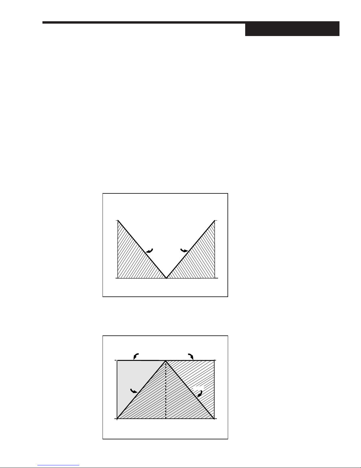
Duplex Output State Examples
The following Duplex examples represent a variety of ways this function can be
set up. PID control examples show the PID output percentage on the horizontal
axis, and On/Off control examples show the process variable on the horizontal
axis. The vertical axes are the output of each physical output. Most of these
examples use the first output as heating and the second output as cooling.
When using PID control, the 535 controller actually displays the PID output. To
relate this output to the actual physical output, locate the PID output on the
horizontal axis. Draw a vertical line at that point. At the intersection of this vertical
line and the respective output line, draw a horizontal line. The physical output is
the value where this horizontal line intersects the respective axis.
The illustrations assumes a manual reset/load line term of 50%. Therefore, at
zero error (process variable equals setpoint) the PID output is 50%.
Duplex with reverse and direct acting outputs
A reverse acting output 1 and a direct acting output 2 with: no offset, no restrictive
outputs limits, and a neutral relative gain with PID control.
PARAMETER SETTINGS
ACTION:1 = REVERSE
ACTION:2 = DIRECT
PID OFST.:1 = 0
PID OFST.:2 = 0
LOW OUT = 0
HIGH OUT = 100
REL. GAIN = 1.0
Out 1
100%
Out 1
Out 2
100%
Out 2
Applications
Figure 7.3
Duplex with reverse and direct acting
outputs
0%
50%100% 0%
PID OUTPUT
0%
Duplex with direct and reverse acting outputs
A reverse acting output 1 and a direct acting output 2 with: no offset, no restrictive
output limits, and a neutral relative gain with PID control.
PARAMETER SETTINGS
ACTION:1 = DIRECT
ACTION:2 = REVERSE
PID OFST.:1 = 0
PID OFST.:2 = 0
LOW OUT = 0
HIGH OUT = 100
REL. GAIN = 1.0
Out 1
(Heat)
100%
0%
Out 1
Out 2
PID OUTPUT
Out 2
Out 1
50%100% 0%
(Cool)
Out 2
100%
0%
Figure 7.4
Duplex with direct and reverse acting
outputs
535-PROF User's Manual Chapter 7 91
 Loading...