

Moons' TSM34P-1AG, TSM34P-3AG, TSM34P, TSM34P-5AG, TSM34P-6AG Hardware Manual
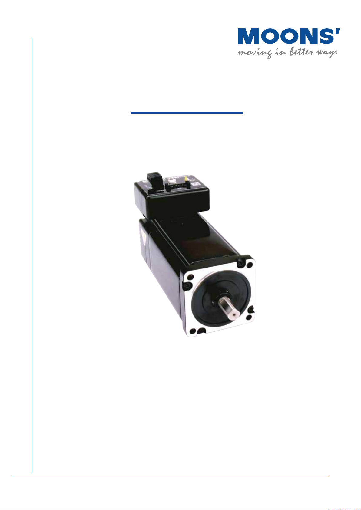
TSM34P
Integrated Step-Servo Motor
Hardware Manual
Rev. 1.0
SHANGHAI AMP&MOONS’ AUTOMATION CO.,LTD.

TSM34P Hardware Manual
Table of Contents
1 Introduction ....................................................................................................... 3
1.1 Features ................................................................................................. 3
1.2 Block Diagram ....................................................................................... 4
1.3 Safety Instructions .................................................................................. 5
2 Getting Started .................................................................................................. 6
2.1 Installing the Software ............................................................................ 6
2.2 Mounting the Hardware .......................................................................... 6
2.3 Choosing a Power Supply ...................................................................... 7
2.3.1 Supply Voltage ....................................................................... 7
2.3.2 Auxiliary Supply Voltage (Keep Alive Function) ....................... 7
2.3.2.1 Keep Alive Recovery with I/O Function ....................... 7
2.3.2.2 Keep Alive Recovery with SCL .................................... 7
2.3.3 Regeneration Clamp ............................................................... 8
2.3.4 Supply Current ........................................................................ 8
3 Installation/Connections .................................................................................... 12
3.1 Connecting the Power Supply ................................................................ 12
3.1.1 Connect Main Power Supply .................................................. 12
3.1.2 Connect Auxiliary Power Supply ............................................ 12
3.2 Connecting the TSM34P Communications ............................................13
3.2.1 Connecting to a PC using RS-232 .......................................... 13
3.2.2 Choosing the Right COM Port ................................................. 13
3.3 Inputs and Outputs ................................................................................. 14
3.3.1 Connector Pin Diagram ........................................................... 14
3.3.2 X1/STEP and X2/DIR High Speed Digital Inputs .................... 16
3.3.3 X3/EN and X4/AR Digital Inputs .............................................. 17
3.3.4 Y1, Y2, Y3 Programmable Outputs ......................................... 18
4 Troubleshooting ................................................................................................ 19
4.1 Status (STAT) LED Error Codes .............................................................. 19
4.2 Auxiliary Power (AUX) LED ..................................................................... 19
5 Reference Materials .......................................................................................... 20
5.1 Torque Speed Curves ............................................................................. 20
5.2 Mechanical Outlines ............................................................................... 20
5.3 Technical Specications ......................................................................... 21
5.4 Optional Accessories ............................................................................... 22
6 Contacting MOONS’..........................................................................................25
Rev. 1.0
0006152016
2
+86 400-820-9661
TSM34P Hardware Manual
TSM34P Models Available
Model
TSM34P-1AG
TSM34P-3AG
TSM34P-5AG
TSM34P-6AG
Communications
RS-232
1 Introduction
Thank you for selecting MOONS’ TSM34P Integrated Motor. The TSM
line of integrated step-servo motors combines servo technology with
an integrated motor to create a product with exceptional features and
broad capabilities. We hope our commitment to performance, quality and
economy will result in a successful motion control project.
1.1 Features
• Programmable, digital servo driver and motor in an integrated package
• Operates from a 24 to 70 volt DC power supply, auxiliary power from 12 to 48 volt DC
• Control Modes
• Position Control Digital Signal type
• Step & Direction
• CW & CCW pulse
• A/B Quadrature (Encoder Following)
• Communications
• RS-232
• 5000 line (20,000 counts/rev) encoder feedback
• Available torque
• TSM34P-1AG: Up to 2.9N•m Continuous
• TSM34P-3AG: Up to 5.6N•m Continuous
• TSM34P-5AG: Up to 7.2N•m Continuous
• TSM34P-6AG: Up to 9.5N•m Continuous
• I/O
• 4 optically isolated digital inputs, with adjustable bandwidth digital noise rejection lter,
5 to 24 volts
• 3 optically isolated digital outputs, 30V/100 mA max.
• Differential encoder outputs (A±, B±, Z±), 26C31 line driver, 20 mA sink or source max
• Technological advances
• Full servo control, Closed loop
• Efcient, Accurate, Fast, Smooth
• Intelligent, Compact
+86 400-820-9661
3
Rev. 1.0
0006152016
TSM34P Hardware Manual
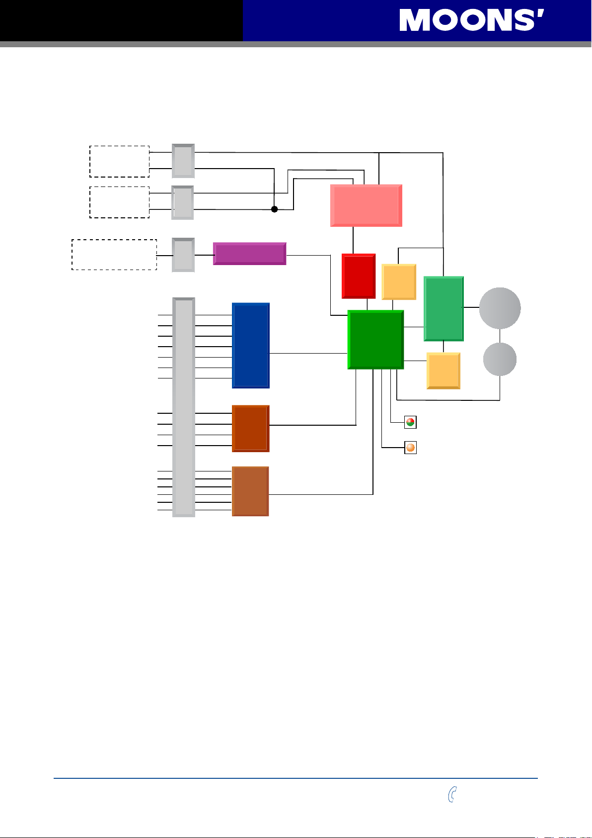
1.2 Block Diagram
TSM34P RS-232
rewoP
24 - 70 VDC
External
Power Supply
12 - 48VDC
External
Power Supply
RS-232 Version
TX,RX,GND
X1+
X1X2+
X2X3
X4
XCOM
Y1
Y2
Y3
YCOM
+
-
+
-
nnoC
nnoC
AUX
mmoC
Port
I/O Connector
Block Diagram
RS-232
Optical
ISO
Optical
ISO
5 Volt DC
Power Supply
3.3VDC
Internal
Logic
Supply
DSP
Driver
Controller
Voltage
Temp
Detect
Status
AUX
MOSFET
PWM
Power
Amplifier
Over
Current
Detect
motor
encoder
Encoder Outputs
A+
A B+
B Z+
Z-
Line
Driver
Rev. 1.0
0006152016
4
+86 400-820-9661

TSM34P Hardware Manual
1.3 Safety Instructions
Only qualied personnel should transport, assemble, install, operate, or maintain this equipment.
Properly qualied personnel are persons who are familiar with the transport, assembly,
installation, operation, and maintenance of motors, and who meet the appropriate qualications
for their jobs.
To minimize the risk of potential safety problems, all applicable local and national codes regulating
the installation and operation of equipment should be followed. These codes may vary from area
to area and it is the responsibility of the operating personnel to determine which codes should be
followed, and to verify that the equipment, installation, and operation are in compliance with the
latest revision of these codes.
Equipment damage or serious injury to personnel can result from the failure to follow all applicable
codes and standards. MOONS’ does not guarantee the products described in this publication
are suitable for a particular application, nor do they assume any responsibility for product design,
installation, or operation.
• Read all available documentation before assembly and operation. Incorrect handling of the
products referenced in this manual can result in injury and damage to persons and machinery. All
technical information concerning the installation requirements must be strictly adhered to.
• It is vital to ensure that all system components are connected to earth ground. Electrical
safety is impossible without a low-resistance earth connection.
• This product contains electrostatically sensitive components that can be damaged by
incorrect handling. Follow qualied anti-static procedures before touching the product.
• During operation keep all covers and cabinet doors shut to avoid any hazards that could
possibly cause severe damage to the product or personal health.
• During operation, the product may have components that are live or have hot surfaces.
• Never plug in or unplug the Integrated Motor while the system is live. The possibility of
electric arcing can cause damage.
Be alert to the potential for personal injury. Follow recommended precautions and safe operating
practices emphasized with alert symbols. Safety notices in this manual provide important
information. Read and be familiar with these instructions before attempting installation, operation,
or maintenance. The purpose of this section is to alert users to the possible safety hazards
associated with this equipment and the precautions necessary to reduce the risk of personal injury
and damage to equipment. Failure to observe these precautions could result in serious bodily
injury, damage to the equipment, or operational difculty.
+86 400-820-9661
5
Rev. 1.0
0006152016

TSM34P Hardware Manual
2 Getting Started
The following items are needed:
• a 24 - 70 Volt DC power supply, see the section below entitled “Choosing a Power Supply” for
help in choosing the right one
• If the Keep Alive function is required, an external 12 - 48 volt DC power supply will be needed
for auxiliary power
• a small at blade screwdriver for tightening the connectors (included)
• a PC running Microsoft Windows XP, or Windows 7, 8, or 10
• a MOONS’ programming cable (included)
2.1 Installing the Software
Before using the TSM34P Integrated Step-Servo Motor and Step-Servo Quick Tuner Software in
an application, the following steps are necessary. See the Quick Setup Guide for brief information
on setting up and conguring the PC and drive.
• Download the Step-Servo Quick Tuner from MOONS' website.
• Install the Step-Servo Quick Tuner software application.
• Connect the drive to the PC using the programming cable. (See section 3.2.1 "Connecting to a
PC using RS-232")
• Choose the correct COM port. (See Section 3.2.2 "Choosing the Right COM Port")
• Run the software application.
• Apply power to the drive.
• The software will communicate with the drive and display the model & rmware version.
• Follow the steps in the Step-Servo Quick Tune” to set up.
2.2 Mounting the Hardware
As with any step motor, the TSM34P must be mounted so as to provide maximum heat sinking
and airow. Keep enough space around the Integrated Motor to allow for the airow.
• Never use the drive where there is no airow or where other devices
cause the surrounding air to be more than 40°C (104°F).
• Never put the drive where it can get wet.
• Never use the drive where metal or other electrically conductive
particles can inltrate the drive.
Rev. 1.0
0006152016
6
+86 400-820-9661

TSM34P Hardware Manual
2.3 Choosing a Power Supply
The main considerations when choosing a power supply are the voltage and current requirements
for the application.
2.3.1 Supply Voltage
The TSM34P is designed to give optimum performance at 48 Volts DC. Choosing the voltage
depends on the performance needed and motor/drive heating that is acceptable and/or does not
cause a drive over-temperature. Higher voltages will give higher speed performance but will cause
the TSM34P to produce higher temperatures. Using power supplies with voltage outputs that are
near the drive’s maximum may signicantly reduce the operational duty-cycle.
The extended range of operation can be as low as 18VDC minimum to as high as 75VDC
maximum. When operating below 18VDC, the power supply input may require larger capacitance
to prevent under-voltage and internal-supply alarms. Current spikes may make supply readings
erratic. The supply input cannot go below 18VDC for reliable operation. Absolute minimum power
supply input is 18VDC. If the input supply drops below 18VDC the low voltage alarm will be
triggered. This will not fault the drive.
Absolute maximum power supply input is 75VDC at which point an over-voltage alarm and fault
will occur. When using a power supply that is regulated and is near the drive maximum voltage
of 75VDC, a voltage clamp may be required to prevent over-voltage when regeneration occurs.
When using an unregulated power supply, make sure the no-load voltage of the supply does not
exceed the drive’s maximum input voltage of 75VDC.
2.3.2 Auxiliary Supply Voltage (Keep Alive Function)
Apart from the main power supply, TSM34 also has an auxiliary power input (AUX power) for
keep alive function of the drive. When the main power supply is off, the AUX power will keep the
logic power on, allowing the drive to remember its state data (motor position, etc.). This allows
the motor to resume operation from its previous position without a homing routine when the main
power is switched back on.
When the main power is removed while the auxiliary power is still on, the drive will show a fault.
If the AUX power supply range is 12-15VDC, the status LED will ash a 3 red, 2 green pattern
indicating the internal voltage is out of range. If the AUX power supply is 15-48VDC, the status
LED will ash a 4 red, 2 green pattern indicating a power supply undervoltage. When the main
power supply is restored the drive will not automatically clear the fault. It will need to be cleared by
the I/O function or SCL commands.
2.3.2.1 Keep Alive Recovery with I/O Function
1. After the main power is removed and the logic remains powered, an undervoltage or internal
bad voltage fault is generated. This alarm will display as a ashing LED pattern which can be
checked by the codes listed in Section 4.1 “Status (STAT) LED Error Codes”.
2. After the main power supply has been restored, the fault must be cleared. Use the alarm reset
function through input 4 (X4) which can be set in the Step-Servo Quick Tuner software. If an
internal bad voltage alarm occurred, the motor will remain disabled. Use the servo on function
through input 3 (X3), also set by the software. If an undervoltage occurred, the motor will reenable
after using the alarm reset function.
3. Resume motion and normal program operation.
2.3.2.2 Keep Alive Recovery with SCL
1. After the main power is removed and the logic remains powered, an undervoltage fault is
+86 400-820-9661
7
Rev. 1.0
0006152016

TSM34P Hardware Manual
generated. This alarm displays as a ashing LED pattern and a bit in the alarm code which can be
read by the host using the AL command.
2. Monitor the main power supply using the IU command. the IU command reads in units of
0.1V. For example, at 24 volts the response to the IU command will be IU=240. See Section 5.3
“Technical Specications” for acceptable operational voltage limits.
3. After the main power supply has been restored, the fault must be cleared. To clear the fault,
send the AR command. The alarm word will become 0. If the fault that occurred wasinternal
voltage out of range, the motor will remain disabled. Send the ME command to enable the motor.
The the fault was undervoltage, the motor will be enabled after the AR command is sent.
4. As the motor may have moved while the main power was lost, the EP command may be used
to verify the motor’s current position.
5. Resume motion and normal program operation.
2.3.3 Regeneration Clamp
If a regulated power supply is being used, there may be a problem with regeneration. When a
load decelerates rapidly from a high speed, some of the kinetic energy of the load is transferred
back to the power supply, possibly tripping the over-voltage protection of a regulated power
supply, causing it to shut down. This problem can be solved with the use of a MOONS’ RC880
Regeneration Clamp. It is recommended that an RC880 initially be installed in an application. If
the “regen” LED on the RC880 never ashes, the clamp is not necessary.
LEDs
Green- Power
Red - Regen on
RC880 Regen Clamp
2.3.4 Supply Current
The maximum supply currents required by the TSM34P are shown in the charts below at different
power supply voltage inputs. The TSM34P power supply current is lower than the winding currents
because it uses switching ampliers to convert a high voltage and low current into lower voltage
and higher current. The more the power supply voltage exceeds the motor voltage, the less
current will be required from the power supply.
It is important to note that the current draw is signicantly different at higher speeds depending
on the torque load to the motor. Estimating how much current is necessary may require a good
analysis of the load the motor will encounter.
Rev. 1.0
0006152016
8
+86 400-820-9661
 Loading...