

Page 1
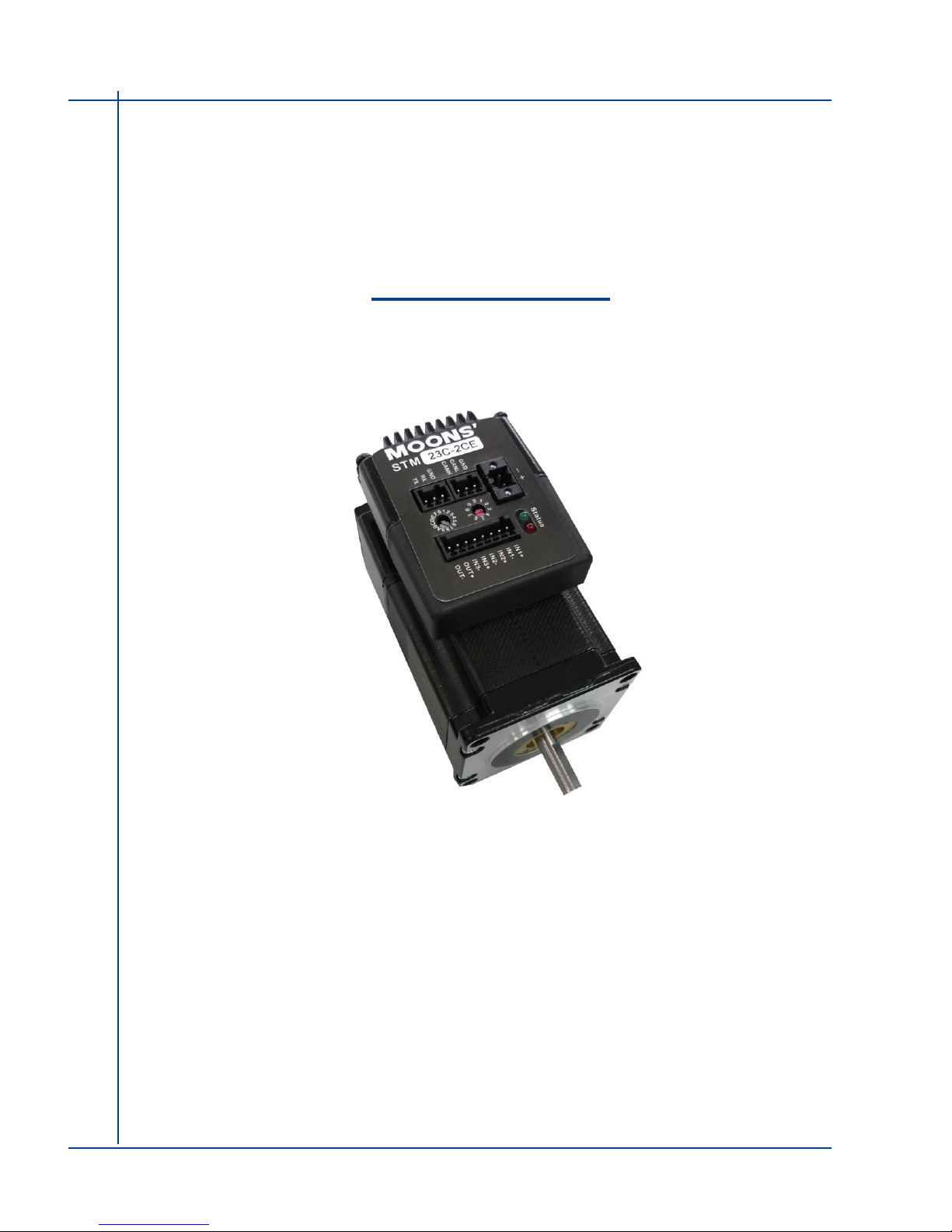
STM23C
Integrated Motor
User Manual
Rev. 1.0
AMP & MOONS’ Automation
Page 2
2
Rev. 1.0
2010/11/03
STM23C User Manual
Contents
1 Introduction ................................................................................ 4
1.1 Features ............................................................................................. 4
1.2 Block Diagram ...................................................................................5
1.3 Safety Instructions .............................................................................6
2 Getting Started ........................................................................... 7
2.1 Installing Software .............................................................................7
2.2 Mounting the Hardware .....................................................................7
2.3 Choosing a Power Supply .................................................................8
2.3.1 Voltage ..................................................................................................8
2.3.2 Current ...................................................................................................9
3 Installation/Connections ......................................................... 12
3.1 Connecting the Power Supply .........................................................12
3.2 Connecting the STM23C Communications ......................................13
3.2.1 Node ID ................................................................................................13
3.2.2 Setting the Bit Rate ..............................................................................13
3.3 Inputs and Outputs ...........................................................................14
3.3.1 Connector Pin Diagram ........................................................................14
3.3.2 IN1 & IN2 Inputs ...................................................................................14
3.3.3 IN3 Input ...............................................................................................15
3.3.4 Programmable Output ..........................................................................16
4 Conguration ........................................................................... 18
4.1 Congurator Menus .........................................................................18
4.1.1 File Menu ..............................................................................................18
4.1.2 Drive Menu ...........................................................................................18
4.1.3 Help Menu ............................................................................................19
4.2 Drive/Revision .................................................................................. 19
4.3 Motor (Integrated Motor) .................................................................. 20
4.3.1 Running Current ...................................................................................20
4.3.2 Accel/Decel Current ..............................................................................20
4.3.3 Idle Current ...........................................................................................20
4.3.4 Idle Current Delay ................................................................................21
4.3.5 Load Inertia ..........................................................................................21
4.3.6 Electronic Damping/Anti-Resonance ....................................................21
4.3.7 Waveform Smoothing ...........................................................................21
Page 3
3
Rev. 1.0
2010/11/03
STM23C User Manual
4.4 I/O ....................................................................................................22
4.5 Encoder (optional) ...........................................................................23
4.6 CANopen .........................................................................................24
4.7 Uploading /Downloading .................................................................. 24
5 Simple Operation ..................................................................... 25
6 Troubleshooting ...................................................................... 27
7 Reference Materials ................................................................. 28
7.1 Mechanical Outlines ........................................................................28
7.2 Technical Specications ...................................................................29
7.3 Torque-Speed Curves ......................................................................31
7.4 SCL Command Reference ..............................................................32
7.5 Drive/Motor Heating ......................................................................... 34
8 Contacting MOONS’ ................................................................ 36
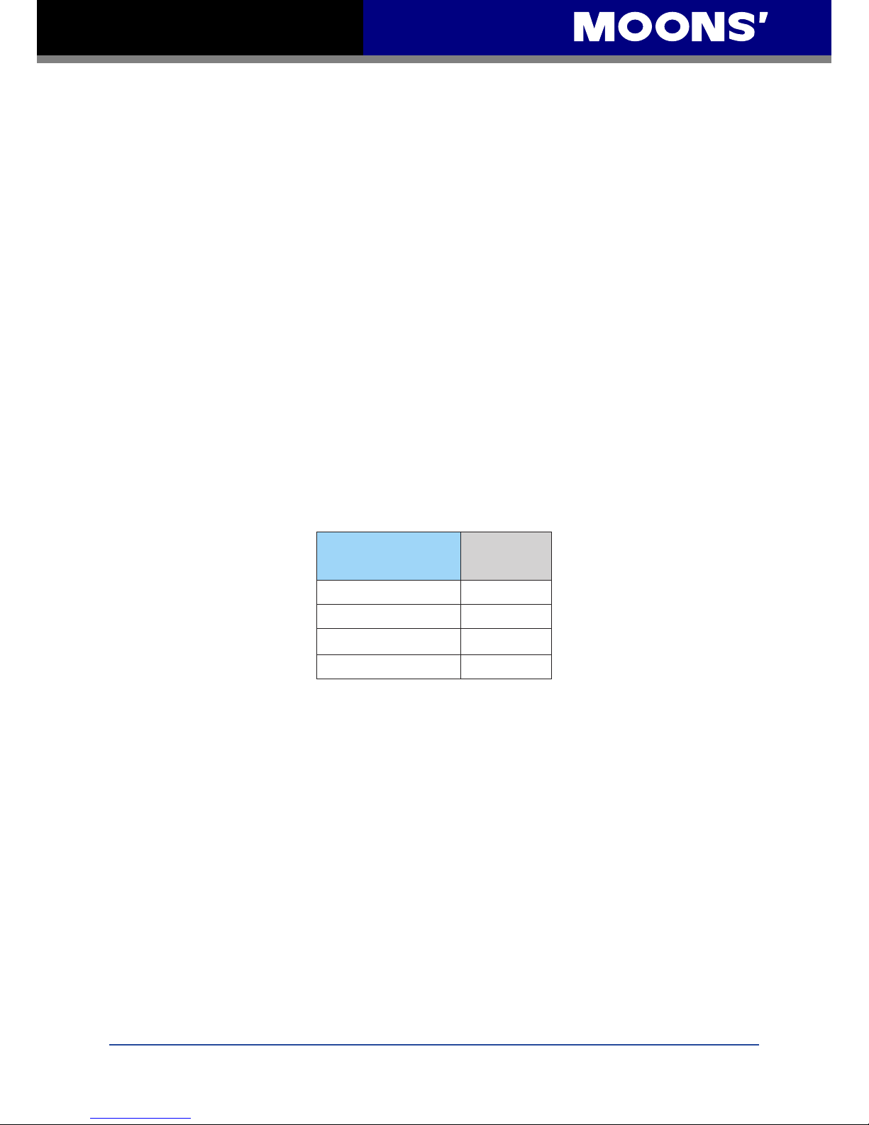
The information in this manual applies to the following products:
Model
Optional
Encoder
STM23C-2CN
STM23C-2CE
STM23C-3CN
STM23C-3CE
Page 4
4
Rev. 1.0
2010/11/03
STM23C User Manual
1 Introduction
Thank you for selecting the MOONS’ STM23C Integrated Motor. The STM23 Series Integrated
Step Motors incorporate DSP driver technology and integrate the drive electronics with the motor.
This provides smooth, precise motion along with ease of set-up and con guration, all at a low
cost. We hope our commitment to performance, quality and economy will result in a successful
motion control project.
1.1 Features
• Programmable, micro-stepping digital step motor and driver in an integrated package
• Operates from a 12 to 70 volt DC power supply
• Modes of Operation (as de ned in CiA DSP402)
• Pro le Position
• Pro le Velocity
• Homing
• Q Programming
• Communications: CANopen Network
• Optional encoder feedback
• Available torque
STM23C-2 up to 0.9 N.m
STM23C-3 up to 1.5 N.m
• I/O
Digital Input ltering both hardware and software
3 optically isolated digital inputs, 5 to 24 volts
1 optically isolated digital output, 30V 100mA
• Technological advances
Mid-band anti-resonance
Sequential Programming through Q Programmer software
Multi-Tasking
Conditional Branching
Math and Data Register manipulation
Page 5
5
Rev. 1.0
2010/11/03
STM23C User Manual
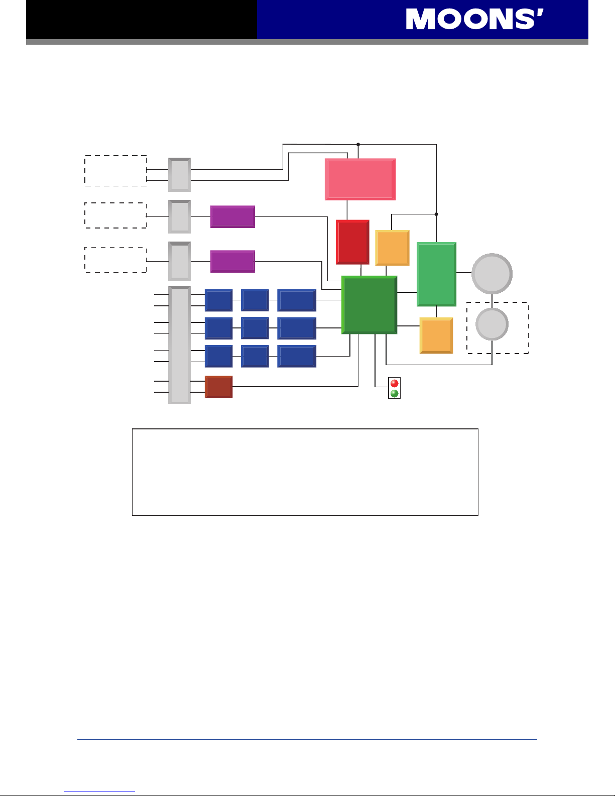
1.2 Block Diagram
Block Diagram
MOSFET
PWM
Power
Amplifier
12-70 VDC
External
Power Supply
Voltage
Temp
Det.
Over
Current
Det.
motor
encoder
5 Volt DC
Power Supply
DSP
Driver
Controller
3.3VDC
Internal
Logic
Supply
STM23C
Optical
Iso
I/O Connector
+
Optical
Iso
Optical
Iso
IN1+
Digital
Filter
Digital
Filter
Digital
Filter
Software
Filter
Software
Filter
Software
Filter
IN1 (5 to 24 Volts)
: CW Jog
: CW Limit
: GP
IN2 (5 to 24 Volts)
: CCW Jog
: CCW Limit
: GP
IN3 (5 to 24 Volts)
: Enable Input
: Reset Input
: GP
I/O Configurations
GP = General Purpose
Status
Optical
Iso
RS-232
CANopen
Comm
Conn
CANopen
Conn
Power
Conn
IN1-
IN2+
IN2-
IN3+
IN3-
OUT+
OUT-
RS-232
TX, RX, GND
CANopen
CANH, CANL, GND
-
OUT (30V, 100mA)
: Brake Output
: Alarm Output
: Motion Output
: GP
Optional
Page 6
6
Rev. 1.0
2010/11/03
STM23C User Manual
1.3 Safety Instructions
Only qualied personnel should transport, assemble, install, operate, or maintain this equipment.
Properly qualied personnel are persons who are familiar with the transport, assembly, installation,
operation, and maintenance of motors, and who meet the appropriate qualications for their jobs.
To minimize the risk of potential safety problems, all applicable local and national codes regulating
the installation and operation of equipment should be followed. These codes may vary from area
to area and it is the responsibility of the operating personnel to determine which codes should be
followed, and to verify that the equipment, installation, and operation are in compliance with the
latest revision of these codes.
Equipment damage or serious injury to personnel can result from the failure to follow all applicable
codes and standards. MOONS’ does not guarantee the products described in this publication
are suitable for a particular application, nor do they assume any responsibility for product design,
installation, or operation.
• Read all available documentation before assembly and operation. Incorrect handling of the
products referenced in this manual can result in injury and damage to persons and machinery.
All technical information concerning the installation requirements must be strictly adhered to.
• It is vital to ensure that all system components are connected to earth ground. Electrical safety
is impossible without a low-resistance earth connection.
• This product contains electrostatically sensitive components that can be damaged by incorrect
handling. Follow qualied anti-static procedures before touching the product.
• During operation keep all covers and cabinet doors shut to avoid any hazards that could pos-
sibly cause severe damage to the product or personal health.
• During operation, the product may have components that are live or have hot surfaces.
• Never plug in or unplug the Integrated Motor while the system is live. The possibility of electric
arcing can cause damage.
Be alert to the potential for personal injury. Follow recommended precautions and safe operating
practices emphasized with alert symbols. Safety notices in this manual provide important
information. Read and be familiar with these instructions before attempting installation, operation,
or maintenance. The purpose of this section is to alert users to the possible safety hazards
associated with this equipment and the precautions necessary to reduce the risk of personal injury
and damage to equipment. Failure to observe these precautions could result in serious bodily
injury, damage to the equipment, or operational difculty.
Page 7
7
Rev. 1.0
2010/11/03
STM23C User Manual
2 Getting Started
The following items are needed:
• a 12 - 70 volt DC power supply, see the section below entitled “Choosing a Power Supply” for
help in choosing the right one
• a small at blade screwdriver for tightening the connectors (included)
• a PC running Microsoft Windows 98, 2000, NT, Me, XP, Vista, or Windows 7
• the MOONS’ CD (included)
• the included RS-232 programming cable
2.1 Installing Software
Before utilizing the STM23C Integrated Motor and ST Congurator Software in an application, the
following steps are necessary:
• Install the ST Congurator software from the CD. For applications requiring complex motion,
Q Programmer software may be used and should also be installed at this point.
• Connect the drive to the PC using the RS-232 cable.
• Connect the drive to the power supply. See instructions below.
• Launch the software by clicking Start...Programs...MOONS’.
• Apply power to the drive.
2.2 Mounting the Hardware
As with any step motor, the STM23C must be mounted so as to provide maximum heat sinking
and airow. Keep enough space around the Integrated Motor to allow for airow.
• Never use the drive where there is no airow or where other devices cause the
surrounding air to be more than 40°C (104°F).
• Never put the drive where it can get wet.
• Never use the drive where metal or other electrically conductive particles can
inltrate the drive.
• Always provide airow around the drive.
Page 8
8
Rev. 1.0
2010/11/03
STM23C User Manual
2.3 Choosing a Power Supply
The main considerations when choosing a power supply are the voltage and current requirements
for the application.
2.3.1 Voltage
The STM23C is designed to give optimum performance between 24 and 48 Volts DC. Choosing
the voltage depends on the performance needed and motor/drive heating that is acceptable and/
or does not cause a drive over-temperature. Higher voltages will give higher speed performance
but will cause the STM23C to produce higher temperatures. Using power supplies with voltage
outputs that are near the drive maximum may signicantly reduce the operational duty-cycle.
The extended range of operation can be as low as 10 VDC minimum to as high as 75 VDC
maximum. When operating below 18 VDC, the power supply input may require larger capacitance
to prevent under-voltage and internal-supply alarms. Current spikes may make supply readings
erratic. The supply input cannot go below 10 VDC for reliable operation. Absolute minimum power
supply input is 10 VDC. If the Input supply drops below 10 VDC the low voltage alarm will be
triggered. This will not fault the drive.
Absolute maximum power supply input is 75 VDC at which point an over-voltage alarm and
fault will occur. When using a power supply that is regulated and is near the drive maximum
voltage of 75 VDC, a voltage clamp may be required to prevent over-voltage when regeneration
occurs. The RC050 Regeneration Clamp is recommended for the STM23C in this situation (see
3.1 Connecting the Power Supply
below). When using an unregulated
power supply, make sure the no-load
voltage of the supply does not exceed
the drive’s maximum input voltage of
75 VDC.
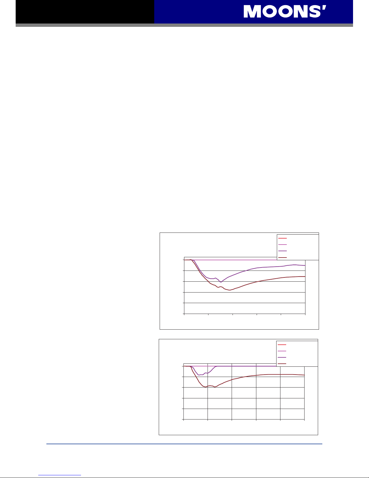
These charts show the duty cycle
of the drive at various speeds and
voltages. See also Section 7.5
on Drive/Motor Heating for more
information.
STM23X-2 Max Duty Cycle vs Speed
5 Amps @ Ambient of 40°C
162 x 162 x 6 (mm) Aluminum Plate
0
20
40
60
80
100
0 10 20 30 40 50
Speed (RPS)
e l c y C y t u D %
12V D uty C ycle
24V D uty C ycle
48V D uty C ycle
65V D uty C ycle
Maximum Duty Cycle vs Speed
STM23X-3 Max Duty Cycle vs Speed
5 Amps @ Ambient of 40°C
162 x 162 x 6 (mm) Aluminum Plate
0
20
40
60
80
100
0 10 2 0 30 4 0 5 0
Speed (RPS)
e l c y C y t u D %
12V D uty C ycle
24V D uty C ycle
48V D uty C ycle
65V D uty C ycle
Page 9
9
Rev. 1.0
2010/11/03
STM23C User Manual
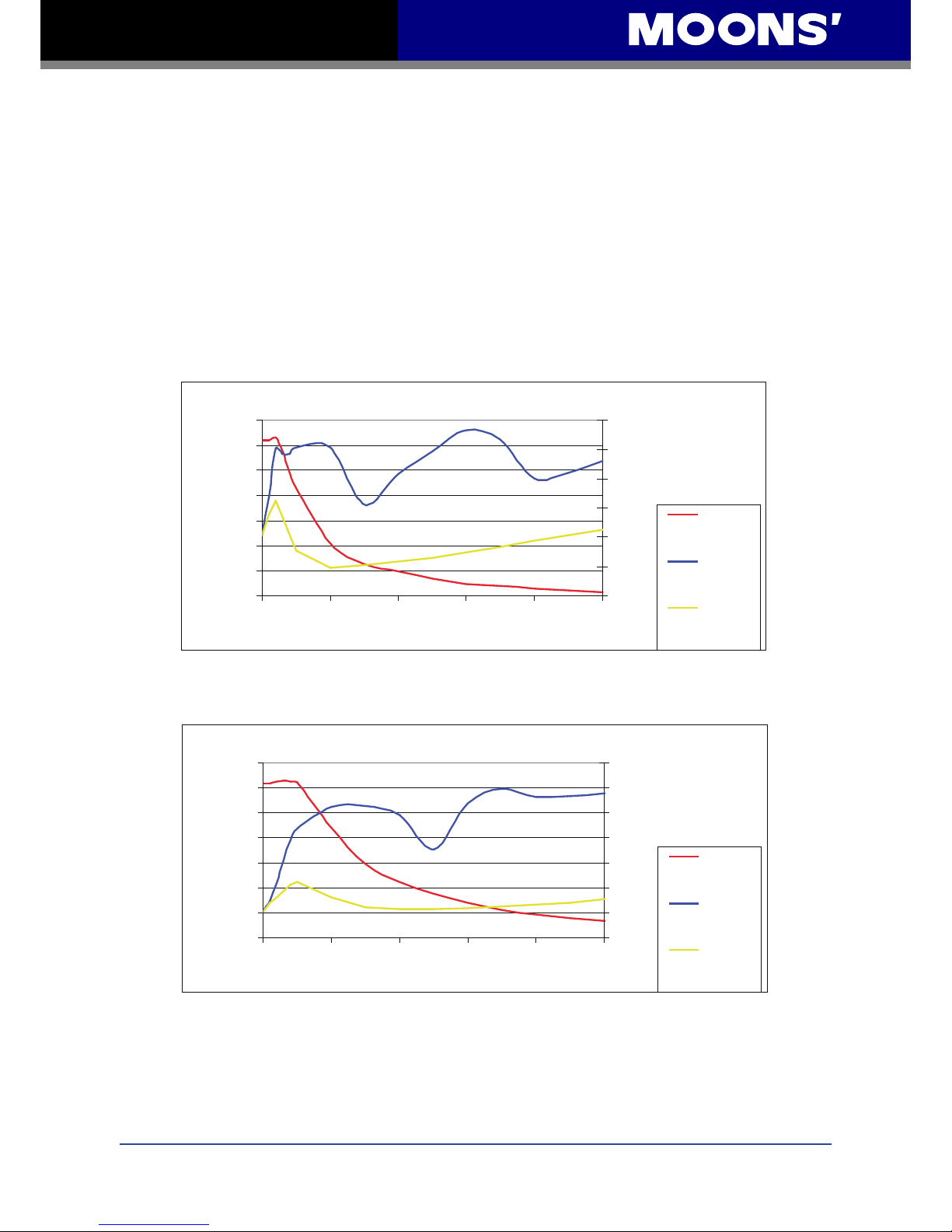
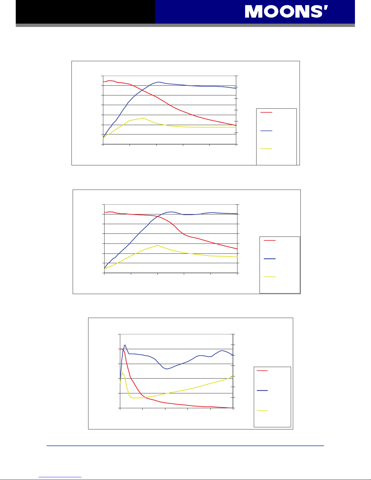
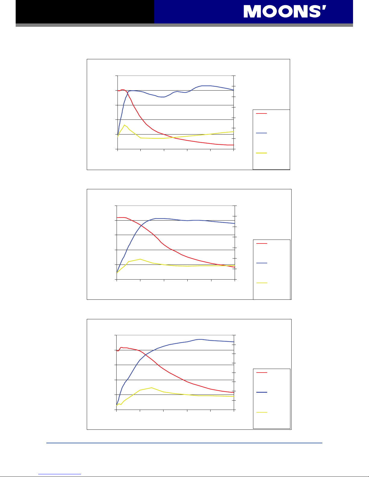
2.3.2 Current
The maximum supply currents required by the STM23C are shown in the charts below at different
power supply voltage inputs. The STM23C power supply current is lower than the winding currents
because it uses switching ampliers to convert a high voltage and low current into lower voltage
and higher current. The more the power supply voltage exceeds the motor voltage, the less
current will be required from the power supply.
It is important to note that the current draw is signicantly different at higher speeds depending
on the torque load to the motor. Estimating how much current is necessary may require a good
analysis of the load the motor will encounter.
STM23-2 12V Power Supply Current
0
0.1
0.3
0.4
0.6
0.7
0.8
1.0
0 1 0 20 3 0 4 0 5 0
Speed (RPS)
Torque ( )
0 .0 0
0 .5 0
1 .0 0
1 .5 0
2 .0 0
2 .5 0
3 .0 0
Amps
Torque
S upply
C u rre nt
S upply
C u rre nt
No Load
N m
.
7
N m
.
STM23-2 24V Power Supply Current
0 1 0 2 0 3 0 4 0 5 0
Speed (RPS)
0 .0 0
0 .5 0
1 .0 0
1 .5 0
2 .0 0
2 .5 0
3 .0 0
3 .5 0
Amps
Torque
S upply
C u rre nt
S upply
C u rre nt
No Load
0
0.1
0.3
0.4
0.6
0.7
0.8
1.0
Torque ( )
N m
.
7
N m
.
Page 10
10
Rev. 1.0
2010/11/03
STM23C User Manual
STM23-2 70V Power Supply Current
0 1 0 2 0 3 0 4 0 5 0
Speed (RPS)
0 .0 0
0 .5 0
1 .0 0
1 .5 0
2 .0 0
2 .5 0
3 .0 0
3 .5 0
Amps
Torq ue
S upply
C u rre nt
S upply
C u rre nt
No Load
0
0.1
0.3
0.4
0.6
0.7
0.8
1.0
Torque ( )
N m
.
7
N m
.
STM23-3 12V Power Supply Current
0 1 0 2 0 30 4 0 50
Speed (RPS)
0 .0 0
0 .5 0
1 .0 0
1 .5 0
2 .0 0
2 .5 0
3 .0 0
3 .5 0
Amps
Torq ue
S upply
C u rrent
S upply
C u rrent
No Lo a d
0
0.4
0.7
1.4
1.8
Torque ( )
N m
.
7
1.1
N m
.
STM23-2 48V Power Supply Current
0 1 0 2 0 3 0 4 0 5 0
Speed (RPS)
0 .0 0
0 .5 0
1 .0 0
1 .5 0
2 .0 0
2 .5 0
3 .0 0
Amps
Torq ue
S upply
C u rrent
S upply
C u rrent
No Load
0
0.1
0.3
0.4
0.6
0.7
0.8
1.0
Torque ( )
N m
.
7
N m
.
Page 11
11
Rev. 1.0
2010/11/03
STM23C User Manual
STM23-3 48V Power Supply Current
0 1 0 2 0 30 4 0 50
Speed (RPS)
0 .0 0
0 .5 0
1 .0 0
1 .5 0
2 .0 0
2 .5 0
3 .0 0
3 .5 0
Amps
Torq ue
S upply
C u rrent
S upply
C u rrent
No Lo a d
0
0.4
0.7
1.4
1.8
Torque ( )
N m
.
7
1.1
N m
.
STM23-3 24V Power Supply Current
0 10 20 3 0 4 0 5 0
Speed (RPS)
0 .0 0
0 .5 0
1 .0 0
1 .5 0
2 .0 0
2 .5 0
3 .0 0
3 .5 0
Amps
Torq ue
S upply
C u rrent
S upply
C u rrent
No Lo a d
0
0.4
0.7
1.4
1.8
Torque ( )
N m
.
7
1.1
N m
.
STM23-3 70V Power Supply Current
0 1 0 20 3 0 40 50
Speed (RPS)
0 .0 0
0 .5 0
1 .0 0
1 .5 0
2 .0 0
2 .5 0
3 .0 0
3 .5 0
4 .0 0
Amps
Torq ue
S upply
C u rrent
S upply
C u rrent
No Lo a d
0
0.4
0.7
1.4
1.8
Torque ( )
N m
.
7
1.1
N m
.
Page 12
12
Rev. 1.0
2010/11/03
STM23C User Manual
3 Installation/Connections
3.1 Connecting the Power Supply
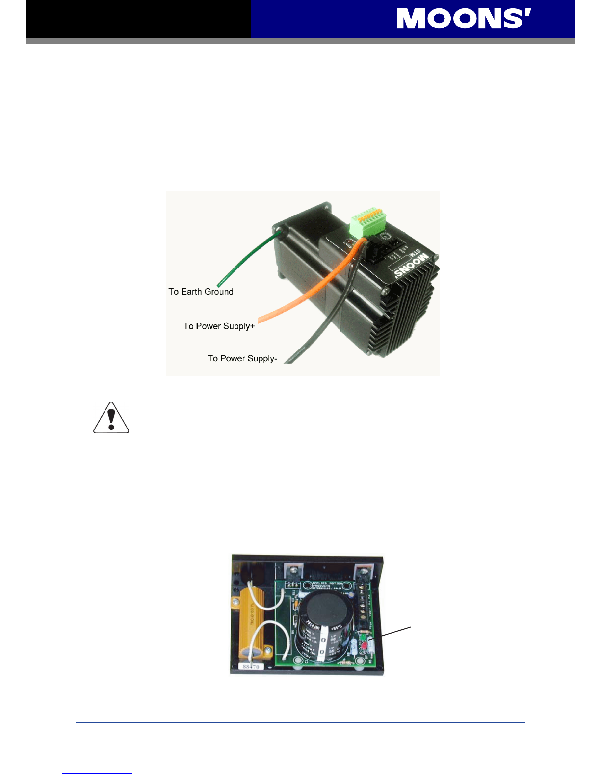
Connect the power supply “+” terminal to the drive “+” terminal and the power supply “-” terminal to
the drive “-” terminal using 16 to 20-gauge wire. The STM23C contains an internal fuse connected
to the “+” terminal. This fuse is not user replaceable. If a user serviceable fuse is desired, install a
4 amp fast acting fuse in line with the “+” power supply lead.
Be careful not to reverse the wires. Reversing the connection may open the
internal fuse on the drive and void the warranty.
If a regulated power supply is being used, there may be a problem with regeneration. When a
load decelerates rapidly from a high speed, some of the kinetic energy of the load is transferred
back to the power supply, possibly tripping the over-voltage protection of a regulated power
supply, causing it to shut down. This problem can be solved with the use of a MOONS’ RC050
Regeneration Clamp. It is recommended that an RC050 initially be installed in an application. If
the “regen” LED on the RC050 never ashes, the clamp is not necessary.
RC050 Regen Clamp
LEDs
Green - Power
Red - Regen
Page 13
13
Rev. 1.0
2010/11/03
STM23C User Manual
3.2 Connecting the STM23C Communications
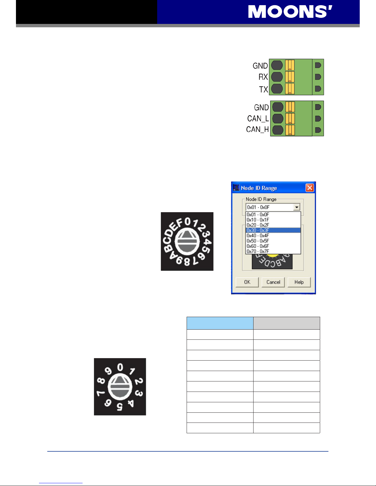
The communications interface for the STM23C is a standard 3-pin
spring clamp. A special cable designed to work with the serial port
for conguration is included. The drives are congured using a
combination of rotary switches and an RS-232 serial link, and then
may be deployed on a distributed CANopen network. The RS-232
interface is used for drive conguration, node ID setting and Q
Program downloading. The CANopen network should be connected
in a daisy-chain fashion, with a 120 ohm terminating resistor at
each end of the network.
Locate the STM23C within 2.5 meters of the PC. Plug the large end
(DB9 connector) of the cable into the serial port of the PC. Plug the 3-pin spring clamp connector
into the appropriate connector on the STM23C. Secure the cable to the PC with the screws on the
DB9 connector.
3.2.1 Node ID
Each node ID on a CANopen network must have a unique
Node ID. The Node ID is congured using a sixteen position
switch to set the lower four bits
of the Node ID while the upper
three bits are congured by using
ST Congurator. CANopen Node
IDs are seven bits long, with a
range of 1 - 127, or 0x01 - 0x7F in
hexadecimal notation. Node ID 0x00
is reserved in accordance with the
DS301 specication.
3.2.2 Setting the Bit Rate
The CANopen network bitrate is set by the ten position switch
on the front of the drive. The bit rate must
be the same for all nodes on the CANopen
network. Any changes to the bit rate require
either a power cycle or a CANopen reset
command to take effect.
Switch Setting Resultant Bit Rate
0
1 Mbps
1
800 kbps
2
500 kbps
3
250 kbps
4
125 kbps
5
50 kbps
6
20 kbps
7
12.5 kbps
8
reserved
9
reserved
Page 14
14
Rev. 1.0
2010/11/03
STM23C User Manual
3.3 Inputs and Outputs
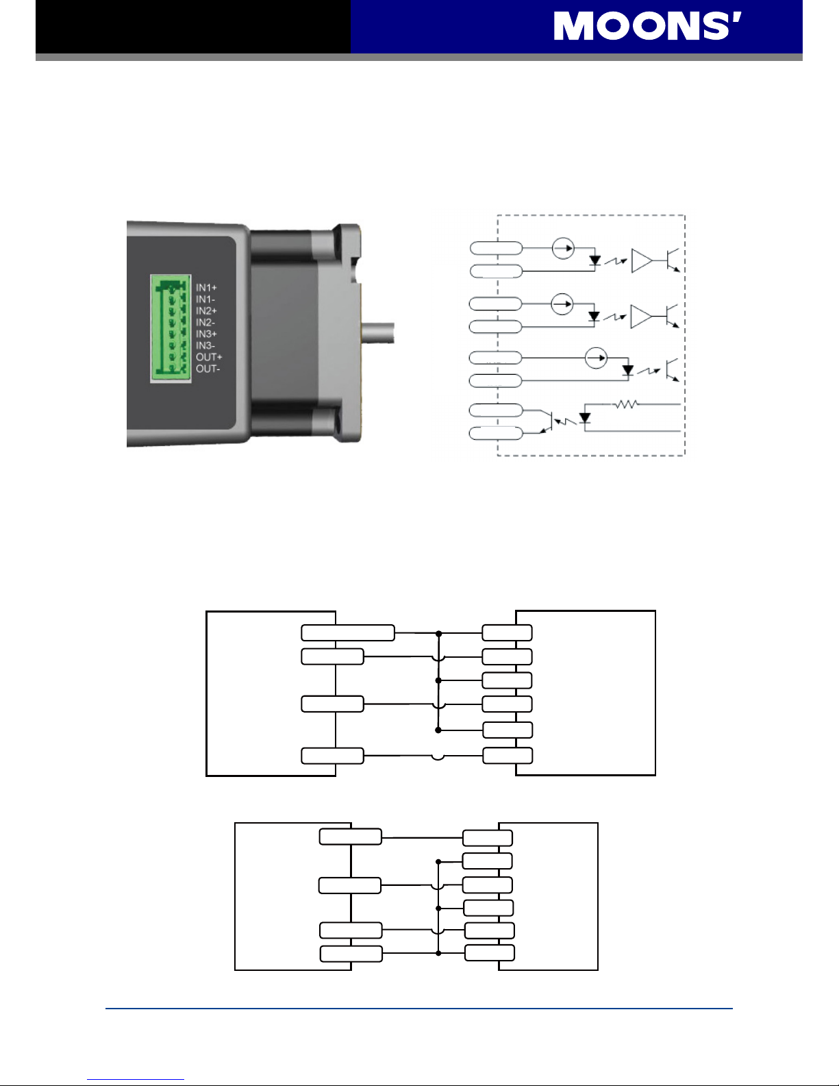
The STM23C has three optically isolated inputs that use 5 to 24 volt logic
3.3.1 Connector Pin Diagram
3.3.2 IN1 & IN2 Inputs
IN1 and IN2 are high speed digital inputs. The diagrams below show how to connect them to
various commonly used devices like sensors, switches, relays, PLCs, etc.
Inside drive
RES
IN1+
IN1-
IN2+
IN2-
IN3+
IN3-
OUT+
OU T-
I/O Connector
STM23
Programmable
digital inputs
Output 2
Output 1
IN1+
IN2+
IN2-
+5v to +24v out
IN1-
IN3+
IN3-
Output 3
Connecting to Indexer with Sinking Outputs
Indexer
With
Sourcing
Outputs
Indexer
With
Sinking
Outputs
STM23
5-24V
High
Speed
Inputs
Output 1
IN1+
Output 2
Output 3
COM
IN1-
IN2+
IN2-
IN3+
IN3-
Connecting to Indexer with Sourcing Outputs
Page 15
15
Rev. 1.0
2010/11/03
STM23C User Manual
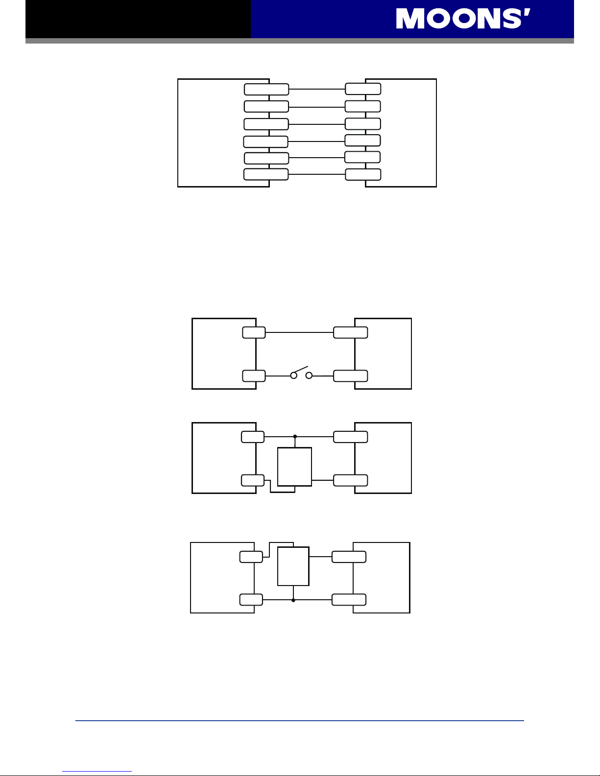
3.3.3 IN3 Input
The IN3 digital input is designed low speed digital input operation between 5 and 24 volts DC. The
diagrams below show how to connect the input to various commonly used devices.
STM23
Programmable
digital inputs
Output 2
Output 1
IN1+
IN2+
IN2-
+5v to +24v out
IN1-
IN3+
IN3-
Output 3
Connecting to Indexer with Sinking Outputs
Indexer
With
Sourcing
Outputs
Indexer
With
Sinking
Outputs
STM23
5-24V
High
Speed
Inputs
Output 1
IN1+
Output 2
Output 3
COM
IN1-
IN2+
IN2-
IN3+
IN3-
Connecting to Indexer with Sourcing Outputs
STM23
5-24V
High
Speed
Inputs
Output 1+
Output 1-
IN1+
IN1-
IN2+
IN2-
Output 2+
Output 2-
Output 3+
Output 3-
IN3+
IN3-
Connecting to Indexer with Differential Outputs
(Many high speed indexers have differential outputs)
Indexer
With
Differential
Outputs
STM23
Programmable
digital inputs
Output 2
Output 1
IN1+
IN2+
IN2-
+5v to +24v out
IN1-
IN3+
IN3-
Output 3
Connecting to Indexer with Sinking Outputs
Indexer
With
Sourcing
Outputs
Indexer
With
Sinking
Outputs
STM23
5-24V
High
Speed
Inputs
Output 1
IN1+
Output 2
Output 3
COM
IN1-
IN2+
IN2-
IN3+
IN3-
Connecting to Indexer with Sourcing Outputs
STM23
5-24V
High
Speed
Inputs
Output 1+
Output 1-
IN1+
IN1-
IN2+
IN2-
Output 2+
Output 2-
Output 3+
Output 3-
IN3+
IN3-
5 to 24
volt
Power
Supply
STM23
Connecting the Input to a Switch or Relay
Switch or Relay
(closed = logic low)
+
-
IN-
IN+
Connecting to Indexer with Differential Outputs
(Many high speed indexers have differential outputs)
5 to 24
volt
Power
Supply
STM23
Connecting an NPN type Proximity Sensor to an input
(when prox sensor activates, input goes low)
+ - IN+
IN-
out
+
NPN
Proximity
Sensor
5 to 24
volt
Power
Supply
STM23
Connecting an PNP type Proximity Sensor to an input
(when prox sensor activates, input goes low)
out
+
PNP
Proximity
Sensor
+
-
IN+
IN+
Indexer
With
Differential
Outputs
Page 16
16
Rev. 1.0
2010/11/03
STM23C User Manual
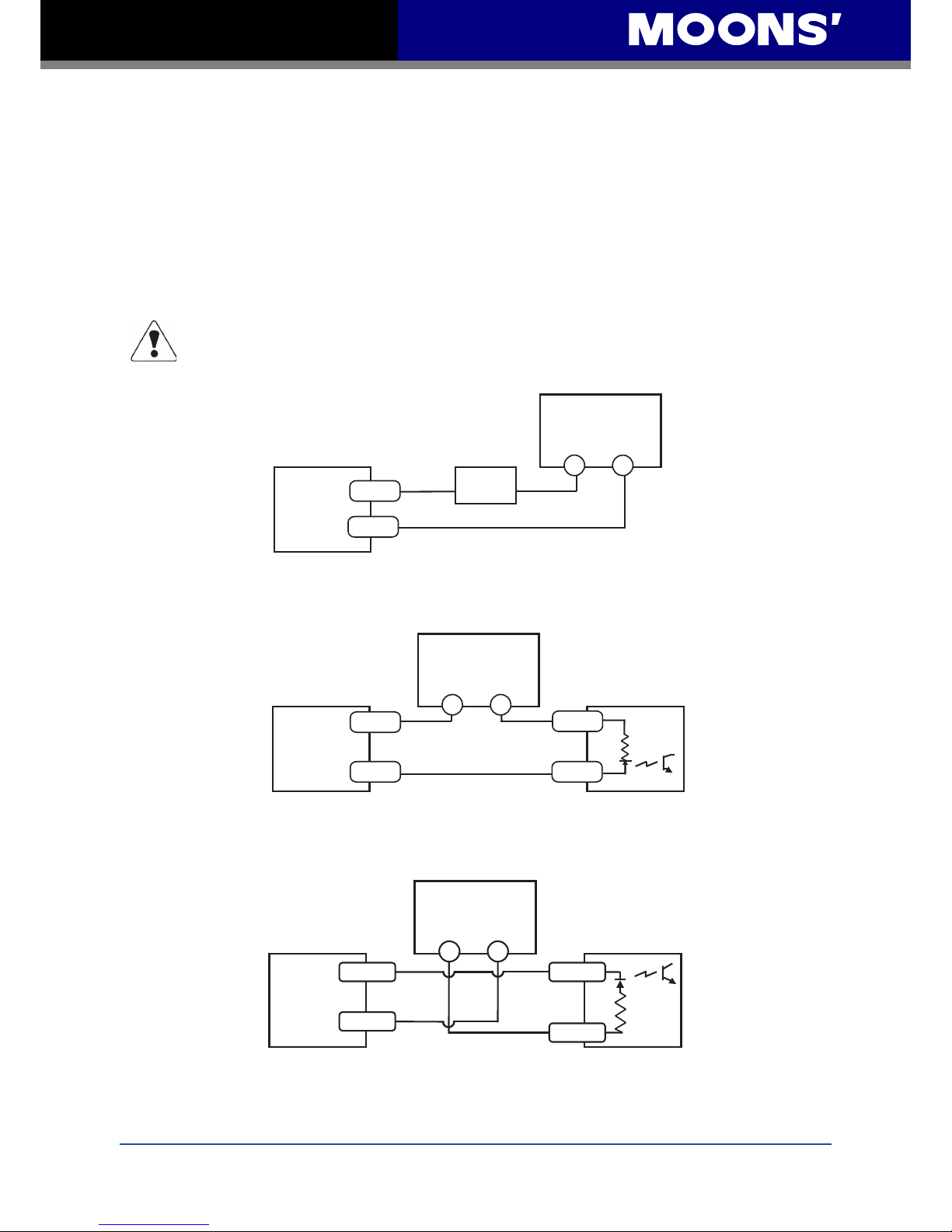
3.3.4 Programmable Output
The STM23C drives feature one optically isolated digital output. This output can be programmed
to automatically control a motor brake, to signal a fault condition, to indicate when the motor is
moving or to provide an output frequency proportional to motor speed (tach signal). Or the output
can be turned on and off by program instructions like Set Output (SO). The output can be used to
drive LEDs, relays and the inputs of other electronic devices like PLCs and counters. The OUT+
(collector) and OUT- (emitter) terminals of the transistor are available at the connector. This allows
the output to be congured for current sourcing or sinking. Diagrams of various connection types
follow.
Do not connect the output to more than 30 volts. The current through the output
terminal must not exceed 100mA.
5 – 24 volt
Power Supply
Connecting a Sourcing Output
PLC
STM23C
OUT+
OU T- IN
COM
5 – 24 volt
Power Supply
STM23C
Connecting a Sourcing Output again
PLC
OUT+
OUT-
IN
COM
-+
5 – 24 volt
Power Supply
Load
STM23C
Connecting a Sinking Output
OUT+
OU T-
Page 17

17
Rev. 1.0
2010/11/03
STM23C User Manual
5 – 24 volt
Power Supply
Connecting a Sourcing Output
PLC
5 – 24 volt
Power Supply
Driving a Relay
1N4935 suppression diode
relay
STM23C
STM23C
OUT+
OUT+
OU T-
OU T- IN
COM
5 – 24 volt
Power Supply
STM23C
Connecting a Sourcing Output again
PLC
OUT+
OUT-
IN
COM
-+
5 – 24 volt
Power Supply
Load
STM23C
Connecting a Sinking Output
OUT+
OU T-
Page 18
18
Rev. 1.0
2010/11/03
STM23C User Manual
4 Conguration
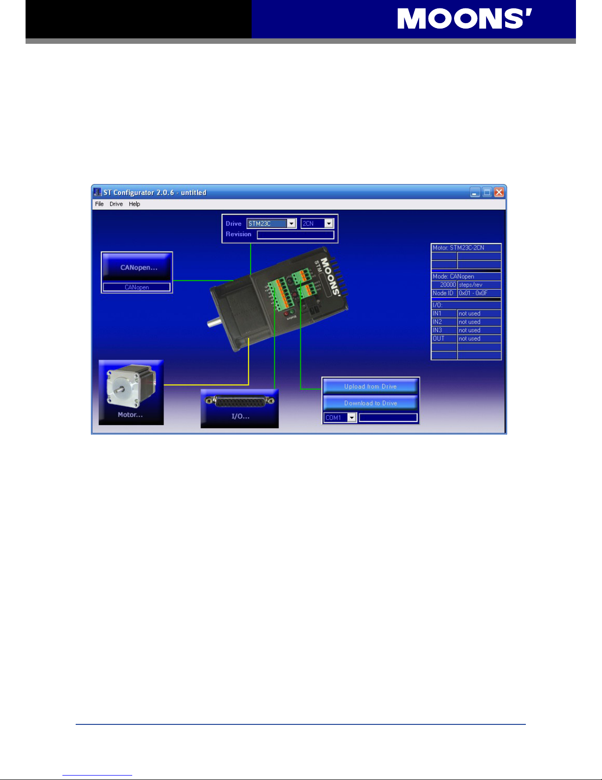
ST Congurator is the PC based software application that is used to congure the STM23C. It can
also upload, save, or open any saved STM23C congurations.
Motor conguration for the STM23C is rather simple as most parameters are xed. Because it is
an integrated motor/driver, the conguration generally has only three elements - the I/O, CANopen
settings, and the Motor. The optional encoder adds a fourth element.
4.1 Congurator Menus
4.1.1 File Menu
In the File Menu previously created congurations can be Opened and new or altered
congurations can be Saved. Any setup can be Printed. The Exit command will close the ST
Congurator.
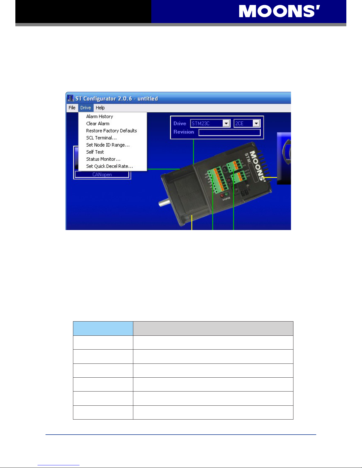
4.1.2 Drive Menu
The Drive menu provides access to several features.
• Alarm History will display the last eight alarms and/or faults.
• If an alarm or fault condition is being displayed, Clear Alarm will clear it.
• Restore Factory Defaults will return the drive to its original factory conguration.
• SCL Terminal allows SCL commands to be entered to test the drive’s response, creating an
opportunity for commands to be learned before host control software is written (see section 5
on Simple Operation below).
Page 19
19
Rev. 1.0
2010/11/03
STM23C User Manual
• Set Node ID Range brings up the same window as the CANopen button (see section 4.6 on
CANopen below.)
• Self Test rotates the motor a half revolution in alternating directions at a low speed to allow
verication that the motor is connected and functioning properly (see section 5 on Simple
Operation below).
• Status Monitor displays real time drive status including:
• State (open or closed) of all inputs
• State of output (click the HI/LO buttons to force an output)
• Motor speed
• Alarms or faults
• Status ags (enabled, motion, jogging, etc.)
The motor can be enabled or disabled from the Status Monitor by clicking the buttons at the
bottom of the display.
• Set Quick Decel Rate allows entry of a decel rate for limits and faults, entered in rev/sec/sec.
4.1.3 Help Menu
The Help Menu allows access to the help screens via Contents, gives Contact information for
MOONS’, links the user to the Website, and gives technical information About ST Congurator.
4.2 Drive/Revision
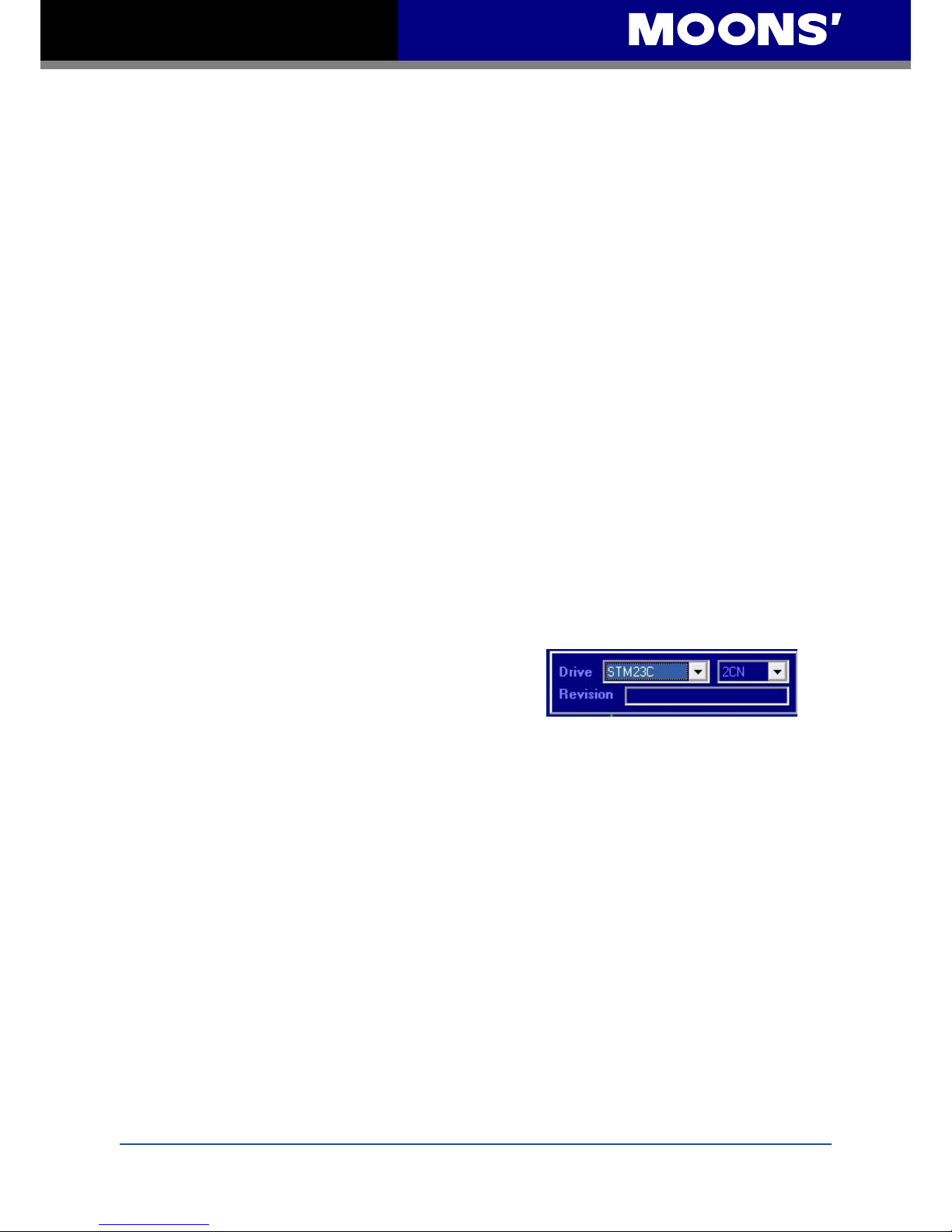
Normally the drive model and revision are automatically
detected when the STM23C is powered up while the
ST Congurator software is active and the STM23C is
connected to the PC serial port. If the box does not list
the correct model after the STM23C is powered up, please check the wired connections (including
the power supply and communications connections.) If the STM23C is intentionally not connected,
the model and revision can be chosen from the drop down list on the upper right. This will provide
the correct screen options and ofine conguration can be accomplished and saved in a le on the
PC.
Page 20
20
Rev. 1.0
2010/11/03
STM23C User Manual
4.3 Motor (Integrated Motor)
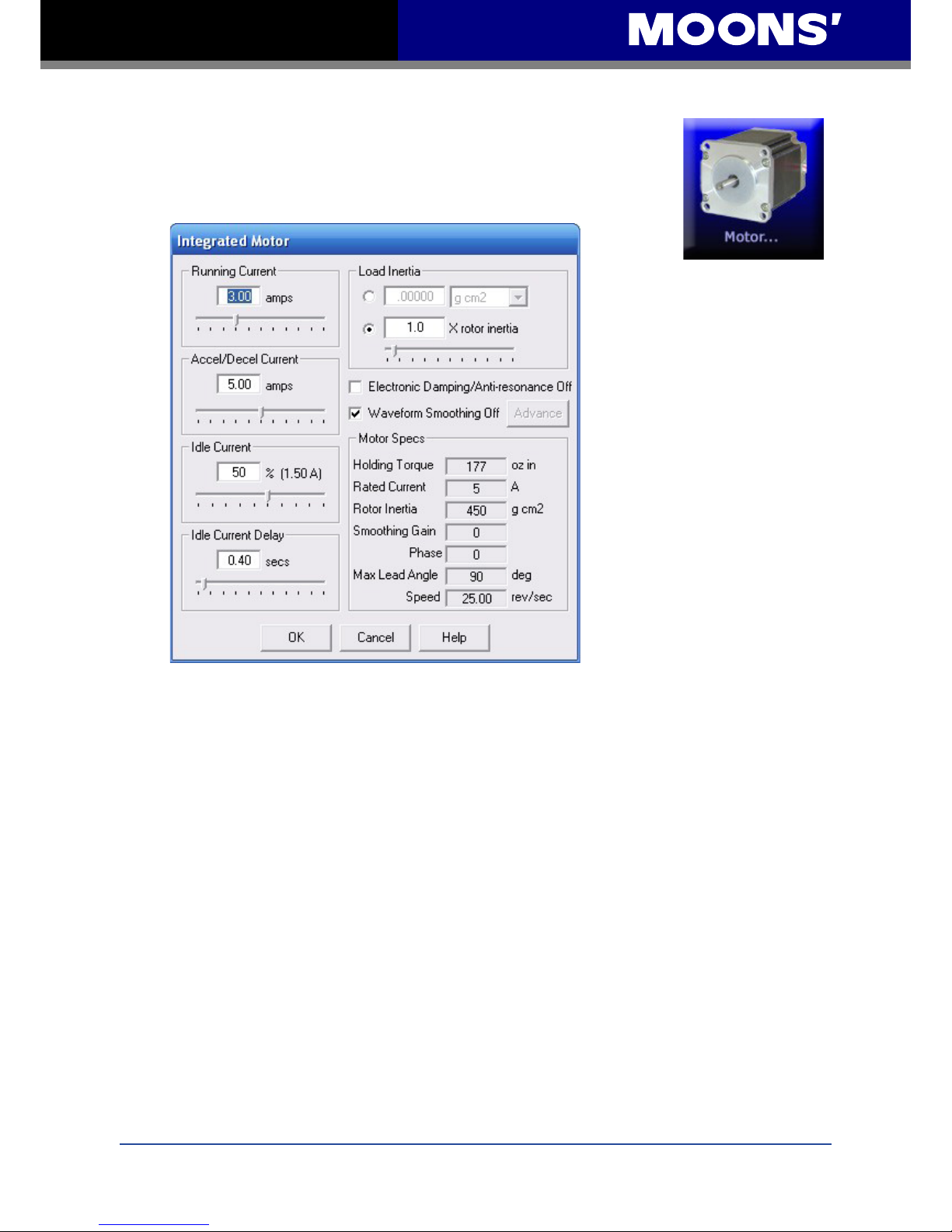
In the Integrated Motor dialog box, operational parameters are dened and
congured. Motor Specs cannot be modied as they are xed according to
the STM23C model selected in the Drive selection box.
4.3.1 Running Current
This value is set by default to a current level that gives good performance at constant speed but
lower than the maximum current to allow the integrated motor to operate at a lower temperature.
If the application requires full torque at full speed, this value can be increased up to the Rated
Current of the integrated motor. If an application is particularly heat sensitive and there is more
torque available than needed, motor heating may be reduced by lowering the running current.
4.3.2 Accel/Decel Current
This value is set by default to the Rated Current of the integrated motor so that maximum torque
is provided during the acceleration or deceleration phase of a move prole. The purpose of the
Accel/Decel Current is to allow the integrated motor to operate at a lower current and therefore
cooler when at a constant speed while still having full torque when needed especially if the load is
high inertia. This value can be reduced for lower torque and operating temperature.
4.3.3 Idle Current
Idle Current is set as a percentage of the Running Current with a maximum setting of 90%. The
Idle Current reduces motor heating by lowering the current when the motor is at rest. In most
cases, the default value of 50% works well. Motor heating may be further reduced by lowering the
Idle Current percentage even more.
Page 21

21
Rev. 1.0
2010/11/03
STM23C User Manual
4.3.4 Idle Current Delay
The Idle Current Delay is the amount of time between when the motor stops and the current is
reduced to the Idle Current value. It is recommended to allow a little time for the motor to settle out
before the current is reduced.
Note: All current values represent the peak value of the sine wave.
4.3.5 Load Inertia
This anti-resonance feature is most effective if the load inertia is set precisely. If this is a known
value, the rst option circle should be clicked, the inertia entered, and units of measurement
selected. If the exact inertia is not known, the second option circle should be selected and an
approximate load to motor inertia ratio entered. This number can be adjusted as needed.
4.3.6 Electronic Damping/Anti-Resonance
The checkbox allows this feature to be enabled or disabled. By default the feature is enabled as
this is recommended. There may be a rare case where disabling the feature is desired.
4.3.7 Waveform Smoothing
By default this is disabled. Consult factory for details when enabling this feature.
Page 22
22
Rev. 1.0
2010/11/03
STM23C User Manual
4.4 I/O
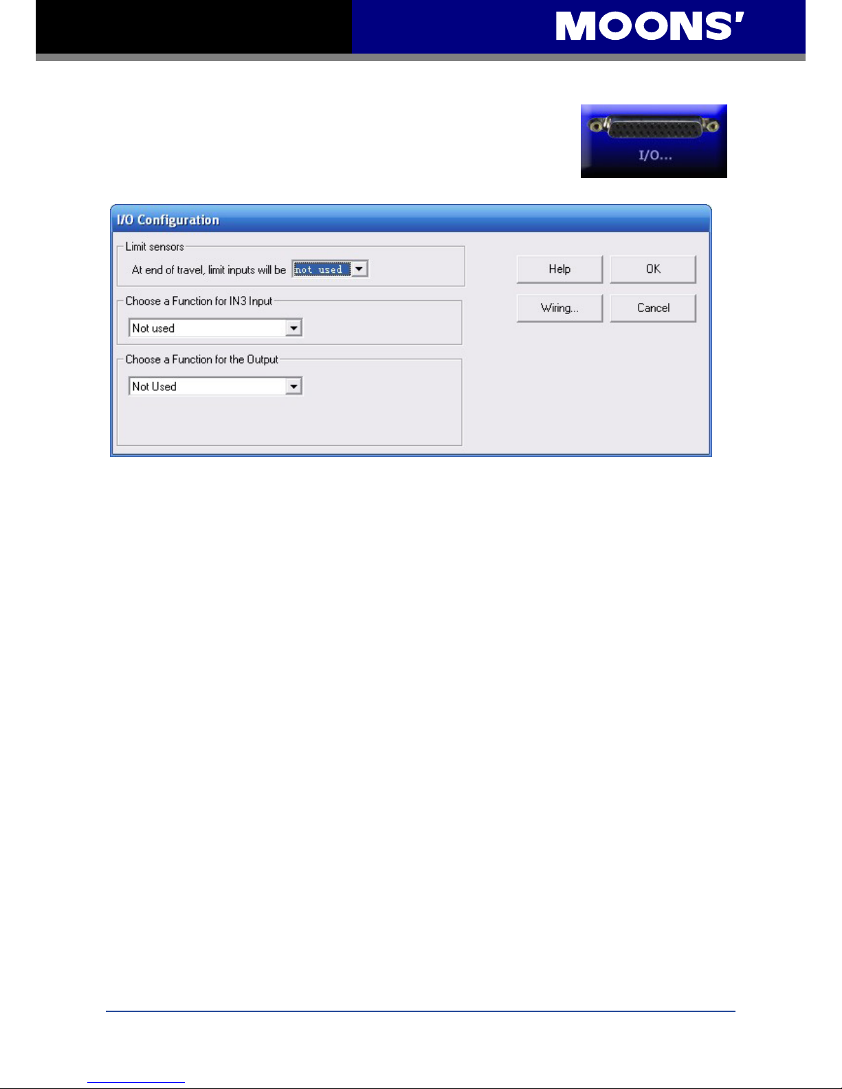
Clicking on the I/O button will bring up the I/O Conguration menu.
Limit Sensors
Options for the IN3 Input are:
• Enable motor when closed - the motor is enabled when there is current owing through the
input and it has no power when the input is open
• Enable motor when open - the motor is enabled when there is no current owing through the
input and it has no power when the input is closed
• Reset alarm when closing - an alarm or fault can be cleared by closing the input
• Reset alarm when opening - an alarm or fault can be cleared by opening the input
• Not used - there is no function for the input, but its state can be read using the SCL Immediate
Inputs (IS), Feed to Sensor (FS) or Feed to Sensor with Safety Distance (FY) command.
Options for Output are:
• Closed on fault - the output will close if a fault occurs
• Open on fault - the output will open if a fault occurs
• Closed to release brake - the output controls a fail safe brake relay
• Open to release brake - the output opens to release the brake
• Closed when moving - the output closes whenever the motor is moving
• Open when moving - the output opens whenever the motor is moving
• Tach out - the output produces pulses relative to the motor position
Page 23
23
Rev. 1.0
2010/11/03
STM23C User Manual
• Not used - there is no function for the output, but it can be controlled using the SCL Set Output
(SO), Feed to Length and Set Output (FO), Immediate High Output (IH), and Immediate Low
Output (IL) commands.
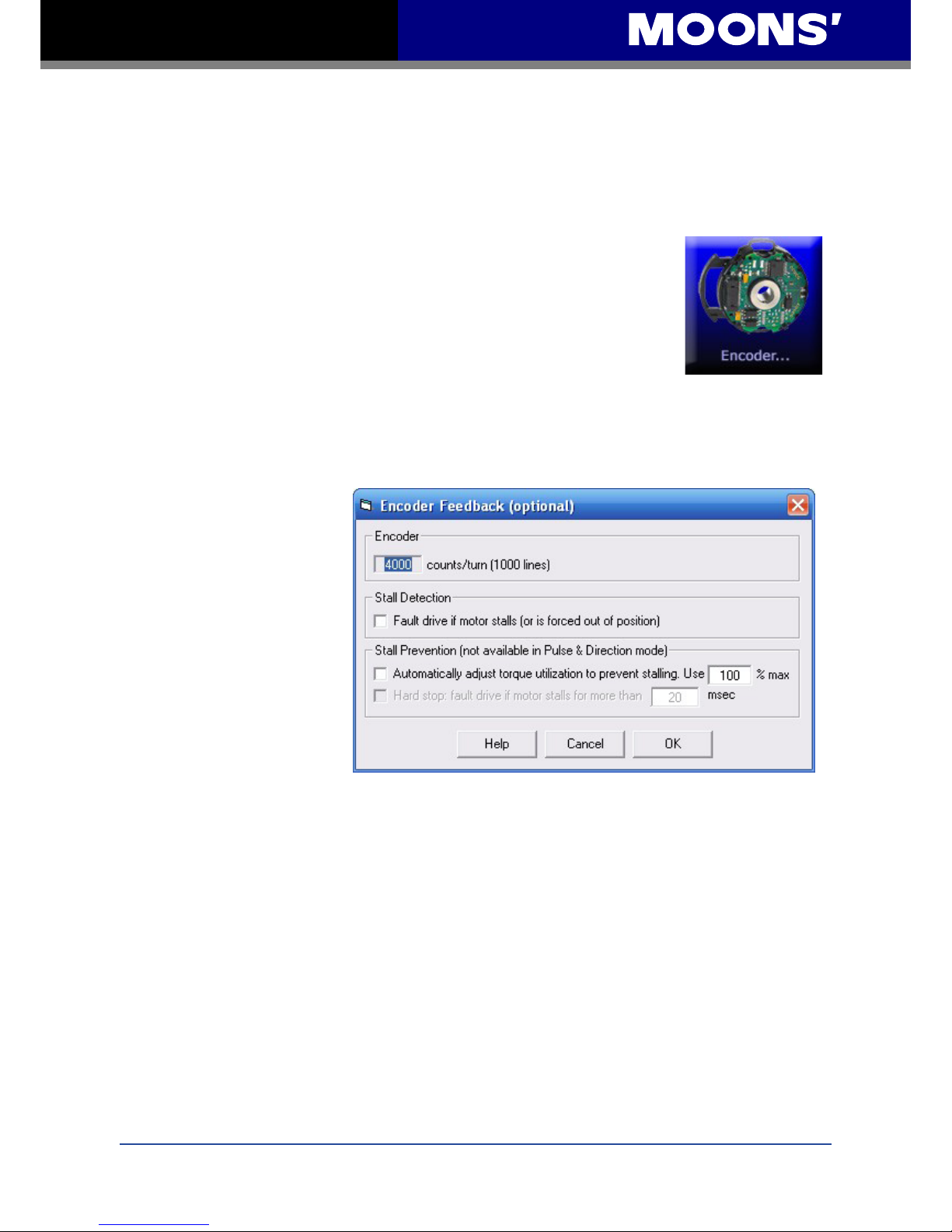
4.5 Encoder (optional)
The Encoder operation on the STM23C is programmed using ST
Congurator. The number of counts/turn cannot be changed as it indicates
the count of the Encoder installed at the time of purchase.
The Stall Detection feature continuously compares the actual motor
position, as reported by the encoder, against the theoretical motor position.
If the motor strays so far out of position that it cannot produce torque, a position fault occurs. This
includes a motor at rest being driven out of position by an external force. Checking the box will
cause the drive to fault when the motor stalls. This fault can then be reported by the Fault output
and cleared by the Alarm Reset input.
The Stall Prevention
feature can prevent many
stalls before they occur. The
encoder is used to monitor
the lead angle of the motor, a
measure of torque utilization.
If the motion prole begins
to demand more torque than
the motor can produce, the
velocity is automatically
reduced before the motor
stalls. Checking the rst box
will engage stall prevention.
A maximum torque utilization
percentage must also be
entered. In the event that the motor cannot move at all, such as after hitting a hard stop, the drive
can be told to fault after a given amount of time when the Hard Stop box is checked and a time
limit is entered.
Page 24
24
Rev. 1.0
2010/11/03
STM23C User Manual
4.6 CANopen
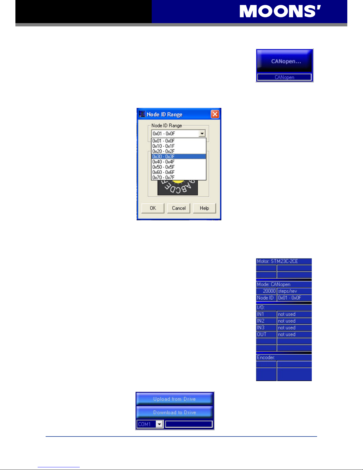
Each node on a CANopen network must have a unique Node ID. On
the STM23C, this is set using both the ST Congurator software and the
sixteen position switch on the front of the drive. CANopen Node IDs are
seven bits long, with a range of 1 - 127, or 0x01 - 0x7F in hexadecimal
notation. The lower four bits, 0x0-0xF are set using the hardware switch, and the upper three bits,
0x0 - 0x7, are set using ST Congurator.
4.7 Uploading /Downloading
Conguring a drive can rst begin by clicking the Upload from Drive
button and uploading the present conguration. This will retrieve any drive
settings that can then be updated and downloaded. The drive conguration
is summarized in the table on the right side of the window as shown
below. Uploading the present conguration rst is not required; setting the
conguration can be done from the ST Congurator application defaults or
a conguration can be opened from a previously saved le.
When conguration updates are complete the summary will show this
information. Not all conguration information is shown here, only a
summary of the basics. The conguration shown in the summary may not
be the same as that in the drive until a download has been completed.
Complete the conguration by clicking the Download to Drive button. This
will download the conguration database to the drive and cause it to reset;
thus updating its operating parameters.
Page 25
25
Rev. 1.0
2010/11/03
STM23C User Manual
5 Simple Operation
After the STM23C is wired and the conguration is downloaded, ST Congurator can be used for
several simple operations. These features are accessible through the drop down list in the Drive
menu.
Self Test
This feature will instruct the motor to rotate a half revolution in alternating directions at a low speed
to verify that the motor is operational.
SCL Terminal
Serial communication commands can be streamed to the drive through the SCL (Host) Terminal.
Some examples are shown below:
Command Description
VE10 sets motor speed to 10 rev/sec
AC100 sets acceleration to 100 rev/sec/sec
DE100 sets deceleration to 100 rev/sec/sec
EG20000 sets electronic gearing resolution to 20000 pulses/rev
DI20000 sets distance to 20000 counts in the CW direction
FL launches feed to length move
Page 26
26
Rev. 1.0
2010/11/03
STM23C User Manual
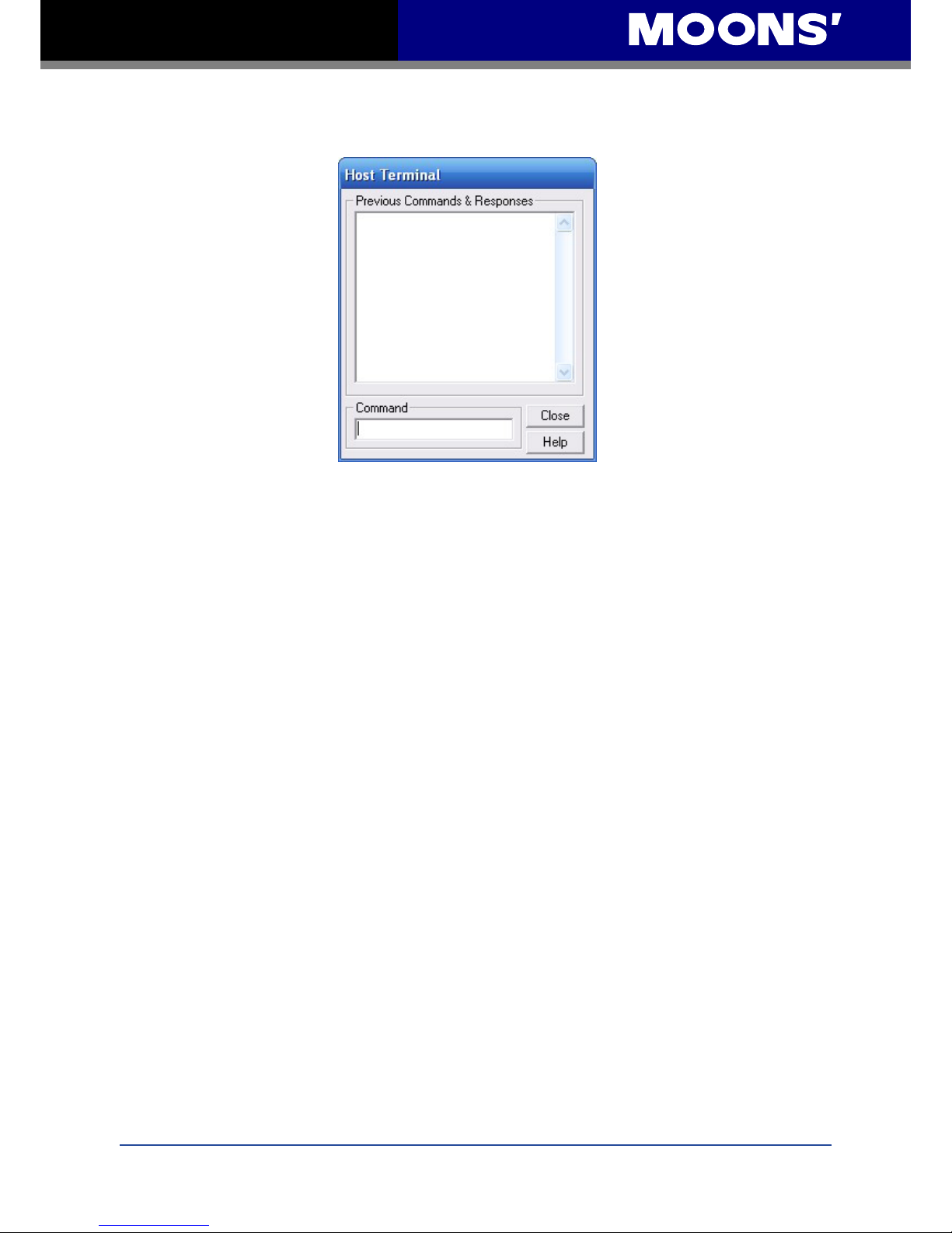
The commands and their responses should appear as shown in the Host Terminal window below:
Every command should have a drive response of “%” which means the command was received
and executed. With this example the motor will move one revolution at 10 rev/sec. For more
information about SCL commands please see the SCL Utility Software Manual on our website at
www.moons.com.cn/www.moons.com.cn/moonsweb/ama/en/software_download.asp
Page 27
27
Rev. 1.0
2010/11/03
STM23C User Manual
6 Troubleshooting
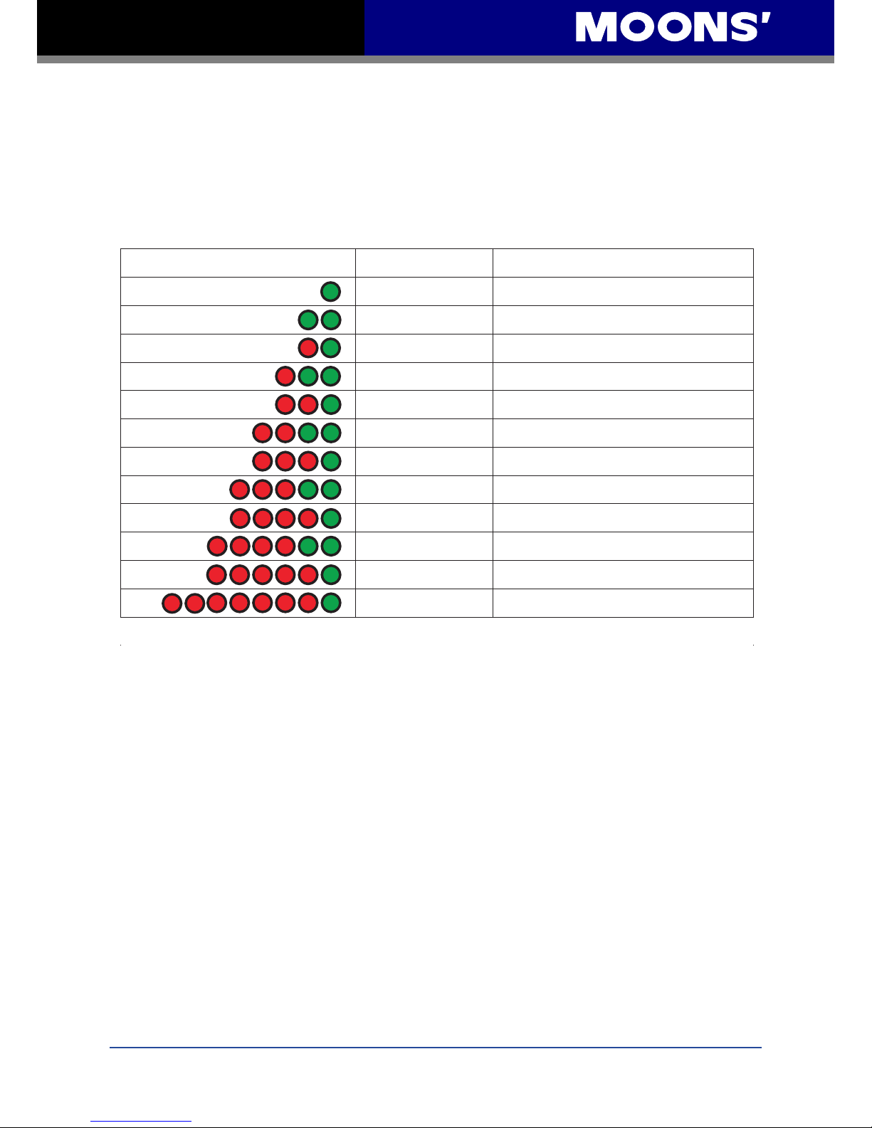
LED Error Codes
The STM23C includes red and green LEDs to indicate status. When the motor is enabled, the
green LED ashes slowly. When the green LED is solid, the motor is disabled. Errors are indicated
by a combination of red and green ashes as follows:
Code
Error
solid green
no alarm, motor disabled
flashing green
no alarm, motor enabled
1 red, 1 green
motor stall
(optional encoder only)
1 red, 2 green
move attempted while drive disabled
2 red, 1 green
CCW limit
2 red, 2 green
CW limit
3 red, 1 green
drive overheating
3 red, 2 green
internal voltage out of range
4 red, 1 green
power supply over voltage
4 red, 2 green
power supply under voltage
5 red, 1 green
over current/short circuit
7 red, 1 green
serial communication error
Page 28
28
Rev. 1.0
2010/11/03
STM23C User Manual
7 Reference Materials
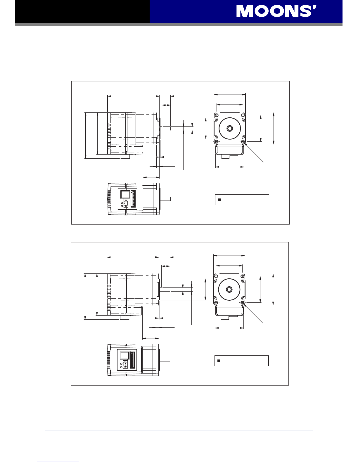
7.1 Mechanical Outlines
92.5±1
77
75
5.85 Flat
Ø 6.35
Ø 38.1
4-Ø 5
47.14
56.4 MAX
56.4 MAX
47.14
20
15
1.6
4.8
50.9
22
Unit:mm
STM23C-2
114.5±1
77
75
5.85 Flat
Ø 6.35
Ø 38.1
4-Ø 5
47.14
56.4 MAX
56.4 MAX
47.14
20
15
1.6
4.8
50.9
44
Unit:mm
STM23C-3
Page 29
29
Rev. 1.0
2010/11/03
STM23C User Manual
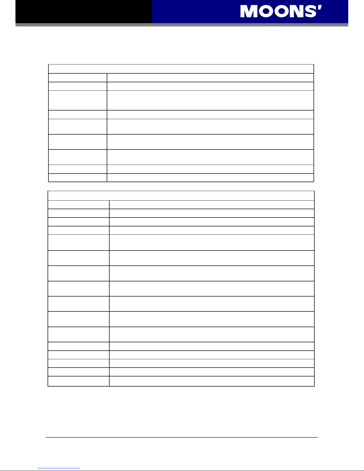
7.2 Technical Specications
Power Amplier
Amplier Type Dual H-Bridge, 4 Quadrant
Current Control 4 state PWM at 20 KHz
Output Torque
STM23C-2 Series – to 0.9 N.m with suitable power supply
STM23C-3 Series – to 1.5 N.m with suitable power supply
Power Supply External 12 - 70 volt power supply required
Input Voltage Range
10 - 75 volts min/max (nominal 12 - 70 volts), voltages outside this range will
cause driver faults and/or may damage the drive
Protection
Over-voltage, under-voltage, over-temp, motor/wriring shorts (phase-to-phase,
phase-to-ground)
Idle Current
Reduction
Reduction range of 0 - 90% of running current after a delay selectable in
milliseconds
Ambient Temperature 0 - 40°C(32 - 104°F) when mounted to a suitable heatsink
Humidity 90% non-condensing
Controller
Current Control Advanced digital current control provides excellent high speed torque
Microstep Resolution Software selectable from 200 to 51200 steps/rev in increments of 2 steps/rev
Speed Range Speeds up to 80 rps
Distance Range Over 10,000,000 revolutions (at 200 steps/rev)
Anti Resonance
(Electronic Damping)
Raises the system-damping ratio to eliminate midrange instability and allow
stable operation throughout the speed range of the motor
Auto Setup
Measures motor parameters and congures motor current control and anti-resonance gain settings
Self Test
Checks internal and external power supply voltages, diagnoses open motor
phases
Microstep Emulation
Performs high resolution stepping by synthesizing coarse steps into ne micro-
steps
Dynamic Smoothing
Software congurable ltering for use in removing spectral components from the
command sequence, reduces jerk, limiting excitation of system resonance.
Dynamic Current
Control
Software congurable for running current, accel current, idle current, to make
motion smoother and the motor run cooler
Multiple Modes Of
Control
CANopen (as dened in CiA DSP402): Prole Position, Prole Velocity, Homing;
Q Programming
Noise Filtering Programmable hardware digital noise lter, software noise lter
Serial Commanding Supports Serial Command Language (SCL)
Encoder Feedback Optional 4000 counts/rev encoder feedback
Position Capture High speed position capture for labeling and packaging applications
Non-Volatile Storage Congurations are saved in FLASH memory on-board the DSP
Page 30
30
Rev. 1.0
2010/11/03
STM23C User Manual
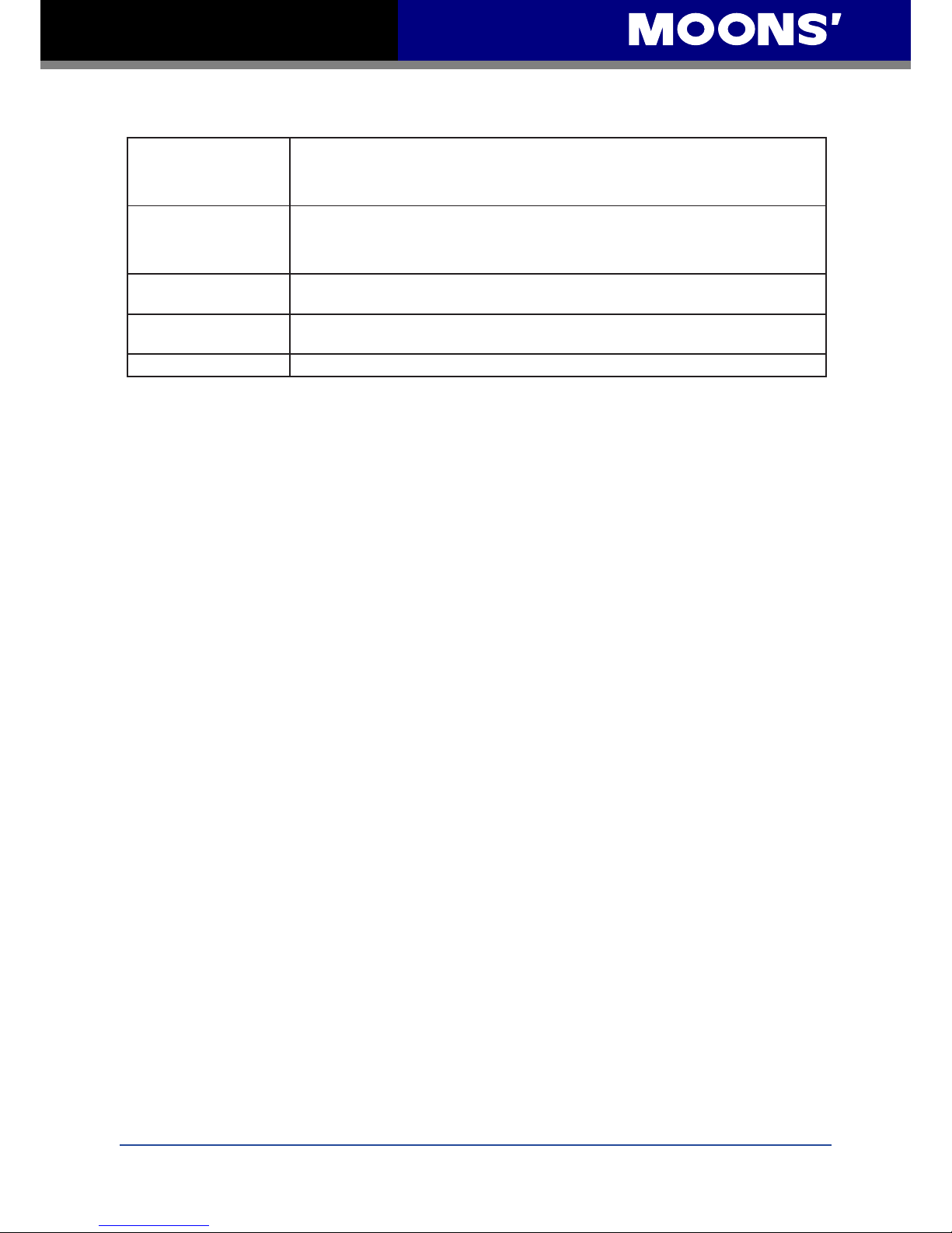
IN1 and IN2 Inputs
IN1+/IN2+/-
Inputs: optically isolated, 5 - 24 volts, min. pulse width 250 ns., max. pulse
frequency 2 MHz
Functions: CW & CCW Jog, CW & CCW Limits, general purpose input
IN3 Input
IN3+/-
Input: optically isolated, 5 - 24 volts, min. pulse width 100 us., max. pulse
frequency 10 KHz
Functions: Motor Enable, Alarm Reset, Home, general purpose input
Output
OUT+/-
Open Collector, 30 volts, 100 mA max, maximum pulse frequency 10 KHz
Functions: Fault, and general purpose programmable
Communication
Interface
CANopen, RS-232; selectable speeds: 12.5, 20, 50, 125, 250, 500, 800 kbps
and 1Mbps
Supply Output +4.8 - 5 volts @ 100mA maximum
Page 31
31
Rev. 1.0
2010/11/03
STM23C User Manual
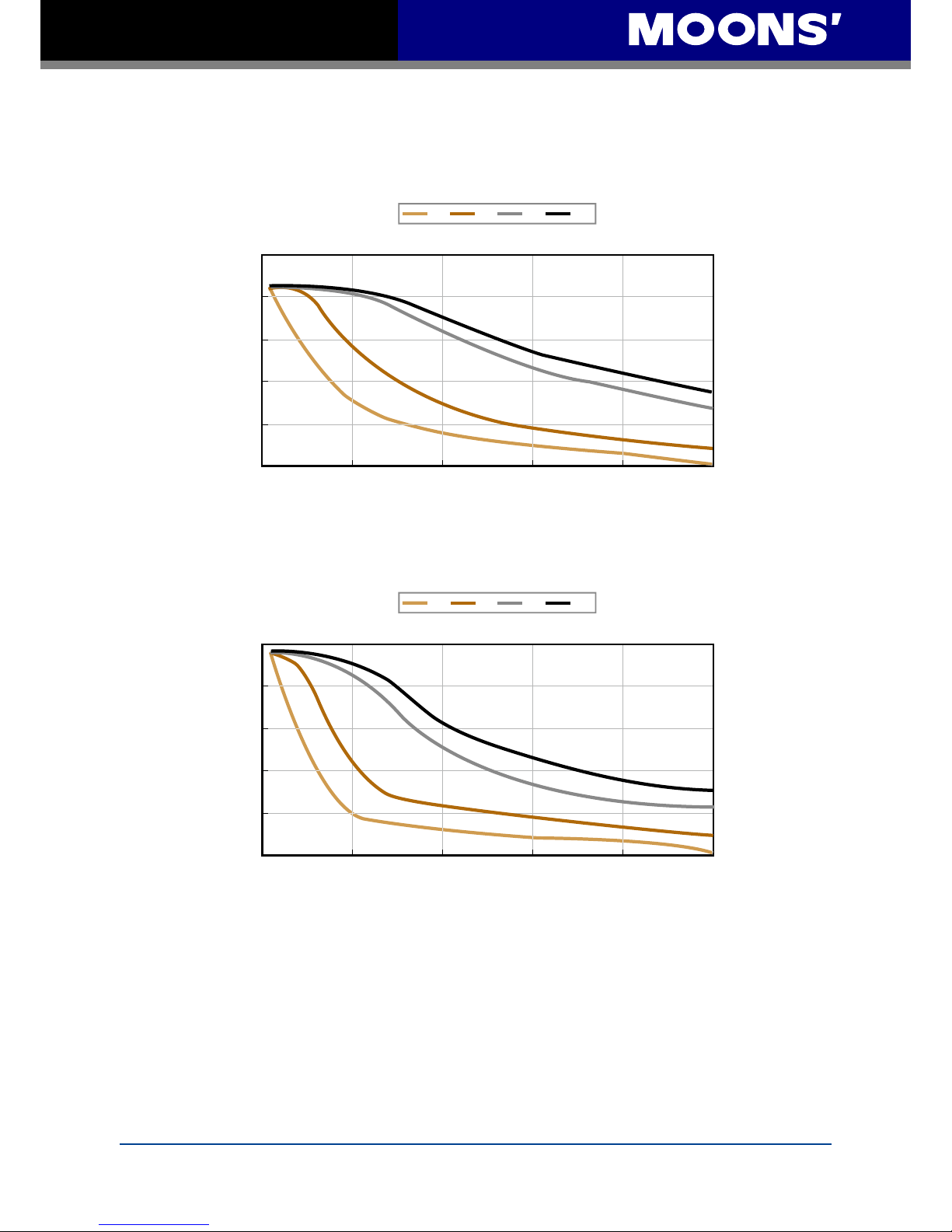
7.3 Torque-Speed Curves
Note: all torque curves were measured at 20,000 steps/rev.
STM23C-2
Speed(rps)
)m N(euqroT
1.0
0.8
0.6
0.4
0.2
0
0 10 20 30 40 50
.
12V
24V
48V
70V
STM23C-3
Speed(rps)
)m N(euqroT
1.5
1.2
0.9
0.6
0.3
0
0 10 20 30 40 50
.
12V
24V
48V
70V
Page 32
32
Rev. 1.0
2010/11/03
STM23C User Manual
7.4 SCL Command Reference
The Serial Command Language (SCL) was developed to give users a simple way to control a
motor drive via a serial port. This eliminates the need for separate motion controllers or indexers
to supply Pulse and Direction signals to the drive. It also provides an easy way to interface to a
variety of other industrial devices such as PLCs and HMIs, which often have standard or optional
serial ports for communicating to other devices. Some examples of typical host devices might be:
• A Windows based PC running MOONS’ software
• An industrial PC running a custom or other proprietary software application
• A PLC with an ASCII module/serial port for sending text strings
• An HMI with a serial connection for sending text strings
SCL commands control the motion of the step motor, use of the inputs and outputs, and congure
aspects of the drive such as motor current and microstep resolution.
In SCL mode, the STM23C receives commands from the host, executing them immediately or
sending them to a command buffer and then executing them directly from the buffer. When used in
the Q Programming mode, It can store a created program for stand-alone operation.
The communications protocol of SCL is simple in that the host initiates all communication, with
one exception. The only time the drive will initiate communication is at power-up. At that time, the
drive will send an identier to tell the software which drive is connected and what the rmware
version is.
There are two types of SCL commands: buffered and immediate. Buffered commands are loaded
into and then executed out of the drive’s command buffer. Buffered commands are executed
one at a time and in sequential order. The buffer can be lled with commands without the host
controller needing to wait for a specic command to execute before sending the next command.
Special buffer commands enable the buffer to be loaded and to pause for a desired time.
Immediate commands are not buffered, but are executed immediately, running in parallel with a
buffered command if necessary. Immediate commands are designed to access the drive at any
time and can be sent as often as needed. This allows a host controller to get information from the
drive at a high rate, most often for checking drive status or motor position.
The basic structure of a command packet from the host to the drive is always a text string followed
by a carriage return. The text string is composed of the command itself, followed by any required
parameters. A carriage return denotes the end of transmission to the drive.
The syntax of the command is
XXAB<cr>
where XX designates the command (always composed of 2 uppercase letters), and A and B
dene the possible parameters. These parameters can vary in length, can be letters or numbers,
and are often optional. Once a drive receives the <cr> (carriage return), it will determine whether
or not it understood the command-if it did, it will either execute or buffer the command. The drive
can also be programmed ahead of time to send a response as to whether or not it understood the
command as well as any error code.
Page 33
33
Rev. 1.0
2010/11/03
STM23C User Manual
Some SCL commands transfer data to the drive for immediate or later use. These data values
are stored in data registers and remain there until new commands change the values or power
is removed from the drive. Some data registers in a drive are Read-Only and contain predened
information about the drive which can also be read through SCL commands.
Because of the intense nature of serial communications required in host mode applications,
there is a serial communication protocol (PR) command available that will adjust a drive’s
serial communications protocol to best t an application. Typically this command is used when
conguring a drive and saved as part of the startup parameters. But it can be used at any time to
dynamically alter the serial communications.
The SCL Utility Software Manual contains the complete command listing as well as instructions on
connecting and conguring the STM23C for use in SCL mode, using the Data Registers and the
Protocol command. It also contains detailed information on:
• Host Serial Communications
• Host Serial Connections
• Alarm and Status Codes
• Working with Inputs and Outputs
The Manual is available from the MOONS’ website at http://www.moons.com.cn/moonsweb/ama/
en/software_download.asp.
under the SCL Utility download section.
Page 34
34
Rev. 1.0
2010/11/03
STM23C User Manual
7.5 Drive/Motor Heating
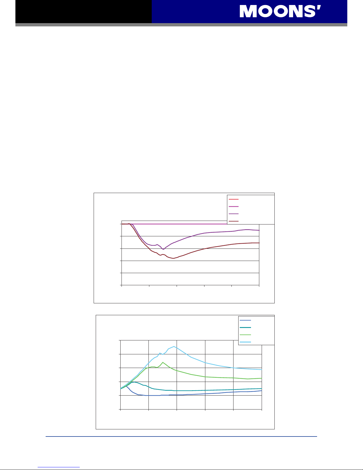
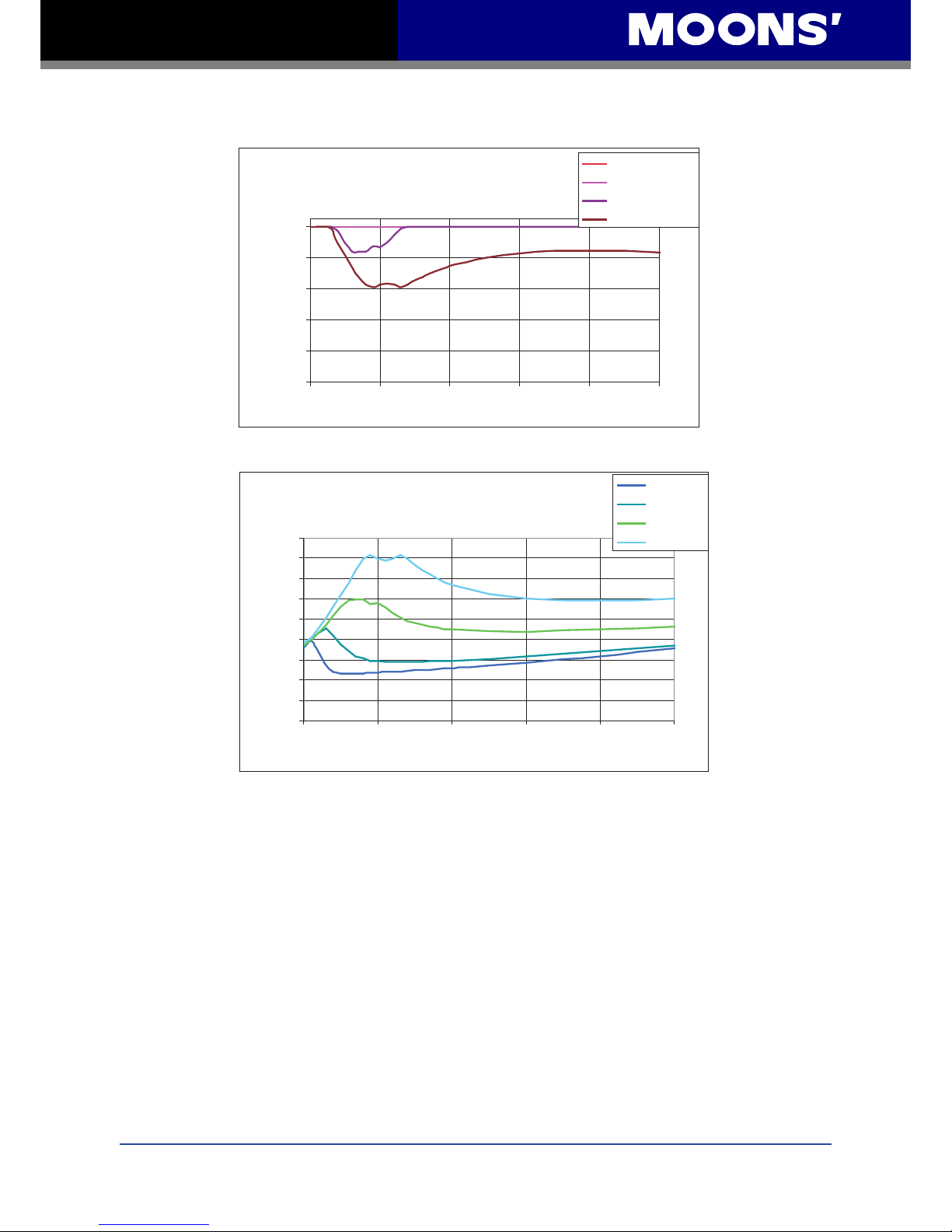
Step motors convert electrical power from the driver into mechanical power to move a load.
Because step motors are not 100% efcient, some of the electrical power turns into heat as it
passes through the motor. The amount of heating is not so much dependent on the load being
driven as on the motor speed and power supply voltage. There are certain combinations of speed
and voltage at which a motor cannot be continuously operated without damage occurring to the
motor.
A step motor typically reaches its maximum temperature after 30 to 45 minutes of operation. A
motor that runs for one minute and then rests for one minute is said to have a duty cycle of 50%.
Five minutes of running and ve minutes of rest is also a 50% duty cycle. However, one hour of
running and one hour of rest has the effect of 100% duty cycle as the motor will reach full and
possible excessive temperature during the rst hour. The actual temperature of the motor depends
on how much heat is conducted, convected or radiated out of it.
The curves below result from measurements made in a 40°C (104°F) environment with the motor
mounted to an aluminum plate sized to provide a surface area consistent with the motor power
dissipation. Results may vary.
STM23X-2 Max Duty Cycle vs Speed
5 Amps @ Ambient of 40°C
162 x 162 x 6 (mm) Aluminum Plate
0
20
40
60
80
100
0 1 0 2 0 3 0 4 0 50
Speed (RPS)
e l c y C y t u D %
12V Duty C ycle
24V Duty C ycle
48V Duty C ycle
65V Duty C ycle
Maximum Duty Cycle vs Speed
STM23X-2 Temperature vs. Speed
5.0 Amps @ Ambient of 40°C
162 x 162 x 6 (mm) Aluminum Plate
0
50
100
150
200
250
0 10 20 30 40 50
Speed (RPS)
) ( e r u t a r e p m e T
12V Tem p
24V Tem p
48V Tem p
65V Tem p
Temperature vs Speed
C °
Page 35
35
Rev. 1.0
2010/11/03
STM23C User Manual
STM23X-3 Max Duty Cycle vs Speed
5 Amps @ Ambient of 40°C
162 x 162 x 6 (mm) Aluminum Plate
0
20
40
60
80
100
0 10 20 3 0 4 0 5 0
Speed (RPS)
e l c y C y t u D %
12V Duty Cycle
24V Duty Cycle
48V Duty Cycle
65V Duty Cycle
STM23X-3 Temperature vs. Speed
5.0 Amps @ Ambient of 40°C
162 x 162 x 6 (mm) Aluminum Plate
0
20
40
60
80
100
120
140
160
180
0 10 20 30 40 50
Speed (RPS)
e r u t a r e p m e T
12V Tem p
24V Tem p
48V Tem p
65V Tem p
) (
C °
Page 36
36
Rev. 1.0
2010/11/03
STM23C User Manual
8 Contacting MOONS’
Room 202,Unit 2,7th Building, Huilongsen International Science & Technology
Industry Park, No.99,kechuang 14th street, Beijing 101111 ,P.R. China
Tel: +86 (0)10 59755578
Fax: +86 (0)10 59755579
Room 302, Building A, Tengfei Creation Center, 55 Jiangjun Road, Jiangning District,
Nanjing 211100, P.R. China
Tel: +86 (0)25 52785841
Fax: +86 (0)25 52785485
168 Mingjia Road, Minhang District,
Shanghai 201107, P.R.China
Tel: +86 (0)21 52634688
Fax: +86 (0)21 52634098
Room 2209, 22/F, Kerry Center, 2008 Renminnan Road, Luohu District,
Shenzhen 518001, P.R.China
Tel: +86 (0)755 25472080
Fax: +86 (0)755 25472081
Headquarters
Shenzhen Branch Office
Beijing Branch Office
Nanjing Branch Office
Qingdao Branch Office
Room E, 10th Floor, 73 Wangjiao Mansion, Hongkong Middle Road, Shinan District,
Qingdao 266071, P.R. China
Tel: +86 (0)532 85879625
Fax: +86 (0)532 85879512
Via Torri Bianche n.1 20059 Vimercate(MB) Italy
Tel: +39 039 62 60 521
Fax: +39 039 96 31 409
Europe Branch: Moons' Industries (Europe) S.R.L.
Service Center
+86-400-820-9661
 Loading...