

SS-EC
Step-Servo EtherCAT Drive
Hardware Manual
SS03-EC-D SS05-EC-D SS10-EC-D
SHANGHAI AMP & MOONS’ AUTOMATION CO.,LTD.
Rev. 1.0
06/21/2016

SS03/05/10-EC Hardware Manual
Table of Contents
1 Introduction ......................................................................................................4
1.1 Features ................................................................................................4
1.2 Block Diagram ........................................................................................5
1.3 Safety Instructions ..................................................................................6
2 Getting Started ..................................................................................................7
2.1 Installing the Software ............................................................................7
2.2 Mounting the Drive .................................................................................8
2.3 Connecting to the PC using mini USB ...................................................8
2.4 Choosing the Right COM Port ................................................................9
2.5 Connecting the Main Power Supply .......................................................9
2.6 Connecting the Auxiliary Power Supply..................................................10
2.7 Choosing a Power Supply ......................................................................10
2.7.1 Supply Voltage .... ...................................................................10
2.7.2 Supply Current ........................................................................10
2.7.3 Auxiliary Supply Voltage (Keep Alive Function) .......................22
2.7.3.1 Keep Alive Recovery with I/O Function ...........................22
2.7.3.2 Keep Alive Recovery with the Master Controller .............22
2.8 Connecting the Motor .............................................................................23
2.9 Connecting the EtherCAT .......................................................................24
2.9.1 EtherCAT Status Indicator LEDs .............................................24
2.10 Connecting the STO .............................................................................25
2.10.1 Safety Precautions ................................................................25
2.10.2 STO Internal Circuit Diagram ................................................25
2.10.3 CN4 Connector diagram ........................................................25
2.10.4 STO Signal Denition ............................................................26
2.10.5 STO Connection Diagrams ...................................................26
3 Inputs and Outputs ............................................................................................27
3.1 Digital Inputs...........................................................................................28
3.1.1 X1, X2, X3 and X4 Digital Inputs .............................................28
3.1.2 X5, X6, X7 and X8 Digital Inputs .............................................29
3.2 Y1, Y2, Y3 and Y4 Digital Outputs .........................................................30
3.3 Analog Inputs..........................................................................................31
3.4 Encoder output .......................................................................................32
4 Control Panel (LED display and keys) ..............................................................33
4.1 Description of Control Panel...................................................................33
4.2 Mode Switch Control ..............................................................................33
4.3 LED display description ..........................................................................35
4.3.1 Decimal Point And Negative Sign Description .........................35
4.3.2 Parameter View Setting ...........................................................35
4.3.3 Parameter Save Setting ..........................................................35
4.3.4 Point To Point Motion Mode ...................................................35
4.3.5 Jog Mode .................................................................................36
4.3.6 Control Panel Lock ..................................................................36
4.4 Status Monitoring Selection Mode..........................................................36
Rev. 1.0
2016/7/30
2
+86-400-820-9661

SS03/05/10-EC Hardware Manual
4.5 Function Control Mode ...........................................................................38
4.5.1 Function Mode Description ......................................................38
4.5.2 Operation Flow Chart ..............................................................39
4.6 Parameter Setting Mode ........................................................................40
4.6.1 Parameter Setting Description ................................................40
4.6.2 Parameter Editing Examples ...................................................41
4.6.3 Parameter list ..........................................................................42
4.7 Control Panel Lock .................................................................................45
4.8 Warning And Fault Display .....................................................................45
4.9 LED Character Reference ......................................................................47
5 Reference Materials ..........................................................................................48
5.1 Drive Mechanical Outlines......................................................................48
5.2 Drive Technical Specications ................................................................49
5.3 Recommended Motors and Specications .............................................50
5.4 Motor Mechanical Outlines .....................................................................51
5.5 Torque Curves ........................................................................................54
5.6 Motor Numbering System ......................................................................56
5.7 Drive Numbering System ......................................................................56
6 Optional Accessories (Sold separately) ................... .........................................57
6.1 Cables ....................................................................................................57
6.2 Mating Connectors .................................................................................59
7 Contacting MOONS’..........................................................................................60
+86-400-820-9661
3
Rev. 1.0
2016/7/30

SS03/05/10-EC Hardware Manual
1 Introduction
Thank you for selecting the MOONS’ SS-EC Step-Servo drive and motor. The SS-EC series
combines servo technology with a stepper motor to create a product with exceptional features and
broad capability. The SS-EC drive can operate as a standard EtherCAT slave using CANopen over
EtherCAT (CoE).
1.1 Features
• Programmable, digital step-servo drive and motor package
• Operates from a 24 to 70 volt DC power supply
• CANopen over EtherCAT (CoE) with full support of CiA402. Based on the widely used
100BASE-TX cabling system and with a baud rate of 100Mbps full-duplex, EtherCAT enables
high speed and highly reliable communication
• Supported modes: Prole Position, Prole Velocity, Prole Torque, Cyclic Synchronous Position,
Cyclic Synchronous Velocity, and Homing; as well as MOONS’ own Q mode
• Dual port EtherCAT communication
• USB port for conguration
• Encoder resolution: 20000 counts/rev for AM17/23/24/34SS motor, 4096 counts/rev for AM11SS
motor
• SS03-EC output current: continuous 3A, boost 4.5A
• SS05-EC output current: continuous 5A, boost 7.5A
• SS10-EC output current: continuous 10A, boost 15A
• 8 optically isolated digital inputs, 5-24VDC high level voltage
• 4 optically isolated digital outputs, max 30V/100mA sink or source current
• 2 analog inputs, can be congured to 0-5V, 0-10V, ±5V or ±10V signal ranges
• Dierential encoder signal output (AOUT +/-, BOUT +/-, ZOUT +/-), 26C31 line driver, 20mA sink
or source current
• Keep Alive function available with an auxiliary power supply
• Front panel with 4 keys and 5 digit LED display for setting parameters
• STO function
Rev. 1.0
2016/7/30
4
+86-400-820-9661
SS03/05/10-EC Hardware Manual
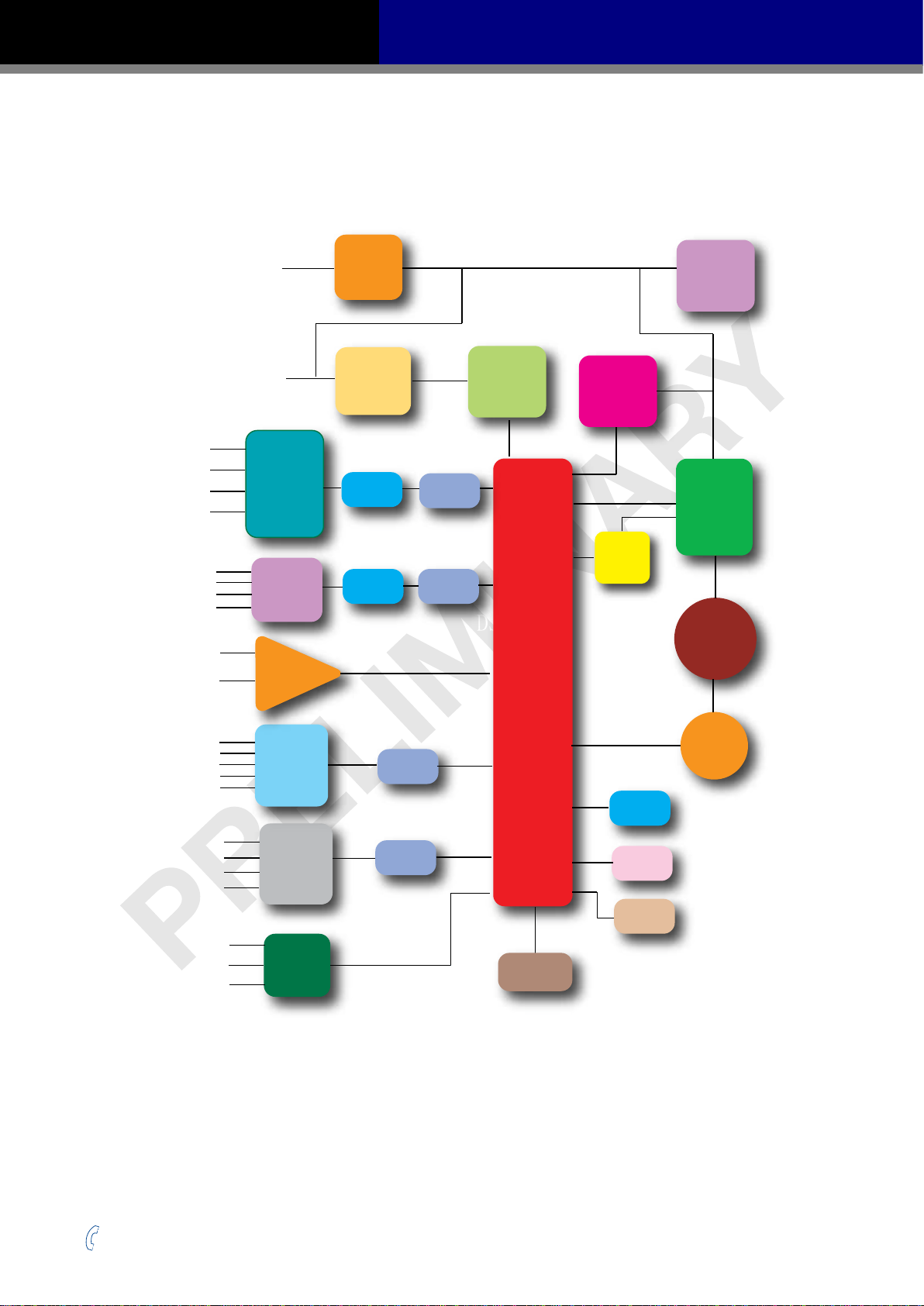
1.2 Block Diagram
SS EtherCAT Block Diagram
Power Supply
(24-70VDC)
Auxiliary Power
(12-48VDC)
X1+
X1-
X2+
X2-
X3+
X3-
X4+
X4-
ANALOG1
ANALOG2
High
Speed
Input
Optical
Isolation
Input
Optical
Isolation
Operational
Amplifter
EMC
Filter
DC Input
Power
Converter
Digital
Filter
Digital
Filter
Software
Filter
Software
Filter
DSP
Internal
Logic
Supply
DSP
Internal
Regen
Clamp
Voltage
Temp.
Det.
Mosfet
PWM
Power
Amplifier
Over
Current
Det.
Motor
X5
X6
X7
X8
XCOM
Y1+/Y2+/Y3+/Y4+/-
A+/-
B+/-
Z+/-
Single
Ended
Input
Isolation
Output
Optical
Isolation
Encoder
Output
Software
Filter
Software
Filter
Encoder
USB
EtherCAT
STO
LED
+86-400-820-9661
5
Rev. 1.0
2016/7/30

SS03/05/10-EC Hardware Manual
1.3 Safety Instructions
Only qualied personnel should transport, assemble, install, operate, or maintain this equipment.
Properly qualied personnel are persons who are familiar with the transport, assembly, installation,
operation, and maintenance of motors, and who meet the appropriate qualications for their jobs.
To minimize the risk of potential safety problems, all applicable local and national codes regulating
the installation and operation of equipment should be followed. These codes may vary from area
to area and it is the responsibility of the operating personnel to determine which codes should be
followed, and to verify that the equipment, installation, and operation are in compliance with the
latest revision of these codes.
Equipment damage or serious injury to personnel can result from the failure to follow all applicable
codes and standards. MOONS’ does not guarantee the products described in this publication
are suitable for a particular application, nor do they assume any responsibility for product design,
installation, or operation.
• Read all available documentation before assembly and operation. Incorrect handling of the
products referenced in this manual can result in injury and damage to persons and machinery.
All technical information concerning the installation requirements must be strictly adhered to.
• It is vital to ensure that all system components are connected to earth ground. Electrical safety
is impossible without a low-resistance earth connection.
• This product contains electrostatically sensitive components that can be damaged by incorrect
handling. Follow qualied anti-static procedures before touching the product.
• During operation keep all covers and cabinet doors shut to avoid any hazards that could
possibly cause severe damage to the product or personal health.
• During operation, the product may have components that are live or have hot surfaces.
• Never plug in or unplug the Integrated Motor while the system is live. The possibility of electric
arcing can cause damage.
Be alert to the potential for personal injury. Follow recommended precautions and safe operating
practices emphasized with alert symbols. Safety notices in this manual provide important
information. Read and be familiar with these instructions before attempting installation, operation, or
maintenance. The purpose of this section is to alert users to the possible safety hazards associated
with this equipment and the precautions necessary to reduce the risk of personal injury and damage
to equipment. Failure to observe these precautions could result in serious bodily injury, damage to
the equipment, or operational diculty.
Rev. 1.0
2016/7/30
6
+86-400-820-9661

SS03/05/10-EC Hardware Manual
2 Getting Started
The following items are needed:
• A 24-70 volt DC power supply, see Section 2.7 “Choosing a Power Supply” for help in choosing
the right one.
• An optional 12-48 volt DC power supply for Keep Alive function
• A compatible SS motor, see Section 5.3 “Recommended Motors and Specications”
• A small at blade screwdriver for tightening the connectors (included)
• A PC running Microsoft Windows XP, Windows 7, Windows 8/10 (32-bit or 64-bit) operating
system
• A mini USB cable for conguration (not included)
• Step-ServoQuickTuner software (available from MOONS’ website)
• A CAT5 cable for EtherCAT daisy chain connection (included)
• An STO connector for CN4 connection (included)
• Optional motor extension cable
• Optional encoder extension cable
• Optional I/O cable
2.1 Installing the Software
Step-ServoQuickTuner is the PC based software application used to congure and perform servo
tuning, drive testing, and evaluation on MOONS’ step-servo products. System servo control gains,
drive functionality, and I/O conguration are set with Step-ServoQuickTuner. It also contains an
oscilloscope function to help to set the servo control gains.
• Download the Step-Servo Quick Tuner from the MOONS’ website and install it.
• Launch the software by clicking Start -- Programs -- MOONS’
• Connect the drive to the PC with the mini USB cable. Select right COM port in the software. See
Section 2.4 “Choosing the Right COM Port”.
• Connect the drive to the power supply.
• Connect the motor to the drive.
+86-400-820-9661
7
Rev. 1.0
2016/7/30
SS03/05/10-EC Hardware Manual
2.2 Mounting the Drive
Use M4 screws to securely mount the SS-EC series drive to a smooth, at metal surface that will
help to conduct heat away from the chassis. If a heat conducting surface is not available, forced
airow from a fan may be required to prevent the drive from overheating.
• Never use the drive in a place where there is no air ow or the surrounding air is
more than 40°C.
• Never put the drive where it can get wet or where metal or other electrically
conductive particle particles can get on the circuity.
• Always provide air ow around the drive. When mounting multiple SS drives near
each other, maintain at least 1.5cm of space between drives.
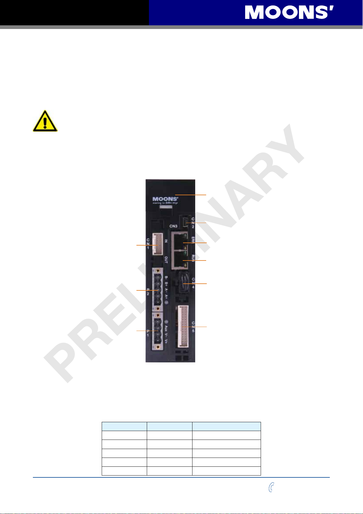
The connectors and other points of interest are illustrated below:
Control Panel
(LED display and keys)
Encoder Connector
Motor Connector
Power Connector
2.3 Connecting to the PC using mini USB
Mini USB
EtherCAT LINK IN
EtherCAT LINK OUT
STO
I/O Connector
Port CN2 is used to connect the drive with PC. Use Step-ServoQuickTuner software to congure
the drive and perform servo tuning and drive testing.
PIN Symbol Function
1 +5V +5V Power Supply
2 D- Data3 D+ Data+
4 - Reserved
5 GND Ground
Rev. 1.0
2016/7/30
8
+86-400-820-9661
SS03/05/10-EC Hardware Manual
P1
V
V
AUX
-
+
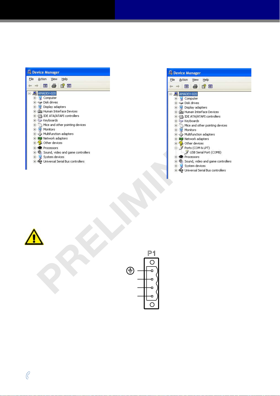
2.4 Choosing the Right COM Port
Open the “Device Manager” on the PC. There may or may not be a “Ports” selection. Connect the
mini USB cable to the PC. The connected COM port should then be displayed. Choose this new
COM(n) port in the Step-Servo Quick Tuner software.
2.5 Connecting the Main Power Supply
Connect power supply “+” terminal to the drive terminal labeled “V+”.
Connect power supply “-” terminal to the drive terminal labeled “V-”.
The SS-EC accepts DC voltage ranging from 24 to 70VDC
Warning: DO NOT reverse the wires
NOTE: DO NOT apply power until all connections to the drive have been made
Power Connector
Read Section 2.7 “Choosing a Power Supply” for more details.
+86-400-820-9661
9
Rev. 1.0
2016/7/30

SS03/05/10-EC Hardware Manual
2.6 Connecting the Auxiliary Power Supply
If the Keep Alive function is needed, an auxiliary power supply is required.
Connect the auxiliary power supply “+” terminal to the drive terminal labeled “AUX”.
Connect the auxiliary power supply “-” terminal to the drive terminal labeled “V-”.
The SS-EC auxiliary Power Supply input accepts DC voltage range from 12 to 48VDC.
Warning: DO NOT reverse the wires
NOTE: DO NOT apply power until all connections to the drive have been made
2.7 Choosing a Power Supply
The main considerations when choosing a power supply are the voltage and current requirements of
the application.
2.7.1 Supply Voltage
The SS-EC is designed to give optimum performance at 24-48 volts DC. Choosing the voltage
depends on the performance needed and the motor/drive heating that is acceptable and/or does not
cause a drive over-temperature. Higher voltages will give higher speed performance but will cause
the SS-EC to produce higher temperatures. Using power supplies with voltage outputs that are near
the drive’s maximum may signicantly reduce the operational duty-cycle.
The extended range of operation can be as low as 18VDC minimum to as high as 75VDC
maximum. When operating below 18VDC, the SS-EC may become unstable. The supply input
cannot go below 18VDC for reliable operation. If the input supply drops below 18VDC the under
voltage alarm will be triggered and the drive will stop working.
Absolute maximum power supply input is 75VDC at which point an over-voltage alarm and fault
will occur. When using a power supply that is regulated and is near the drive maximum voltage of
75VDC, a voltage clamp may be required to prevent over-voltage when regeneration occurs. When
using an unregulated power supply, make sure the no-load voltage of the supply does not exceed
the drive’s maximum input voltage of 75VDC.
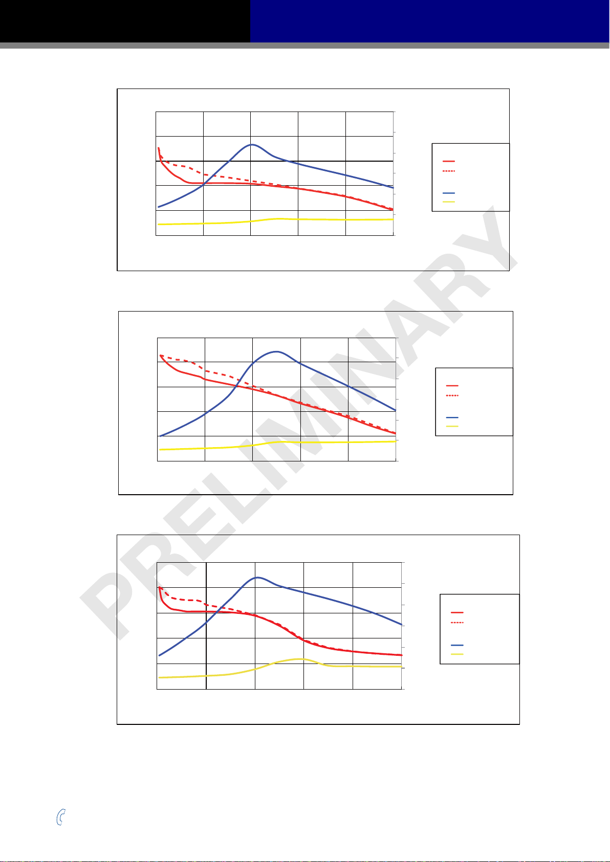
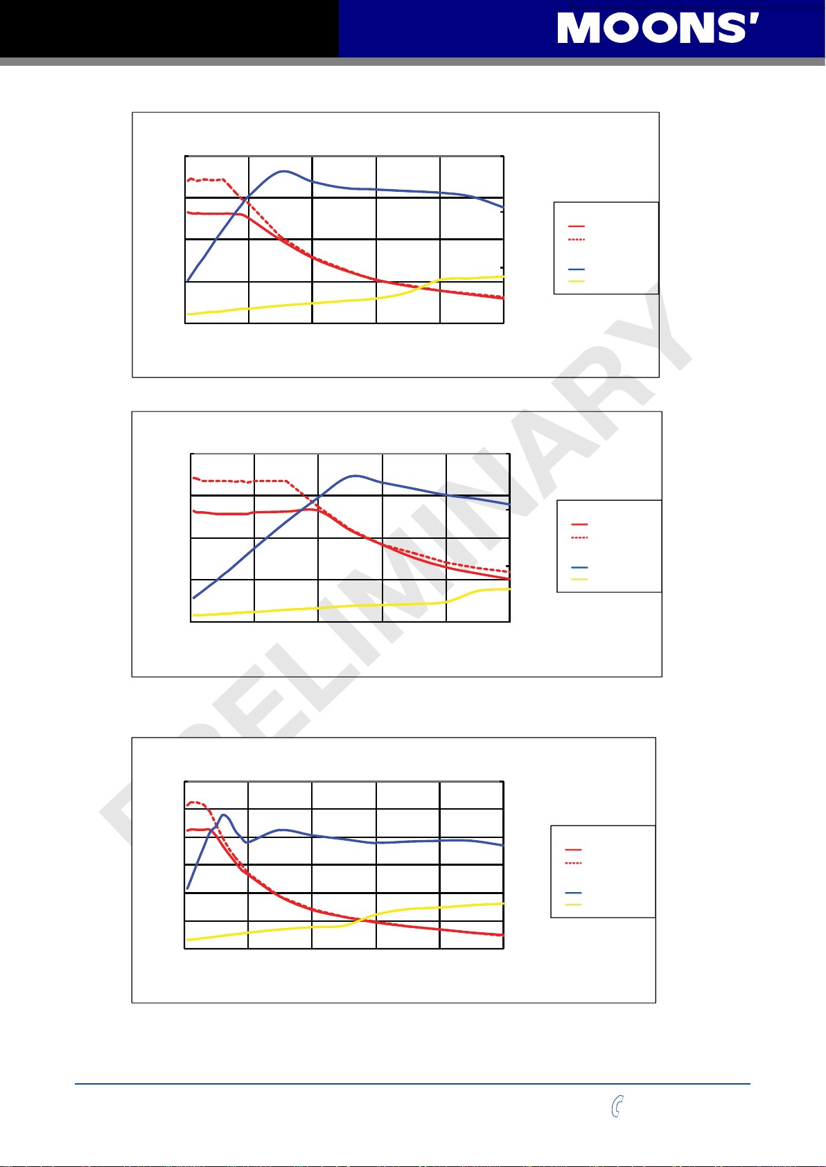
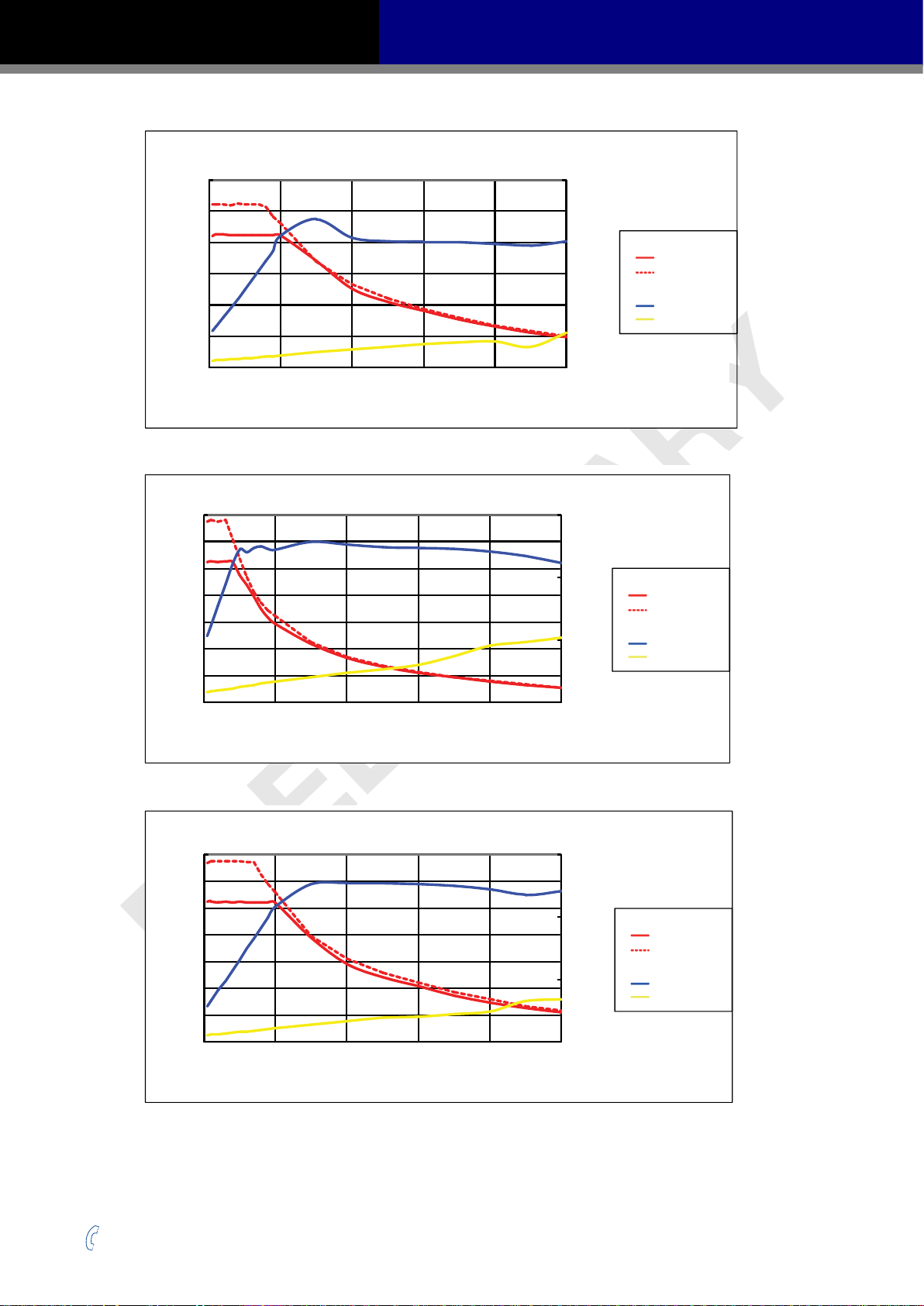
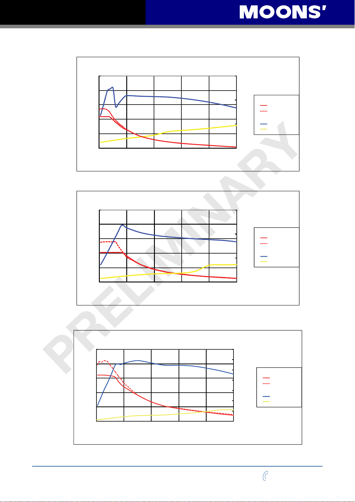
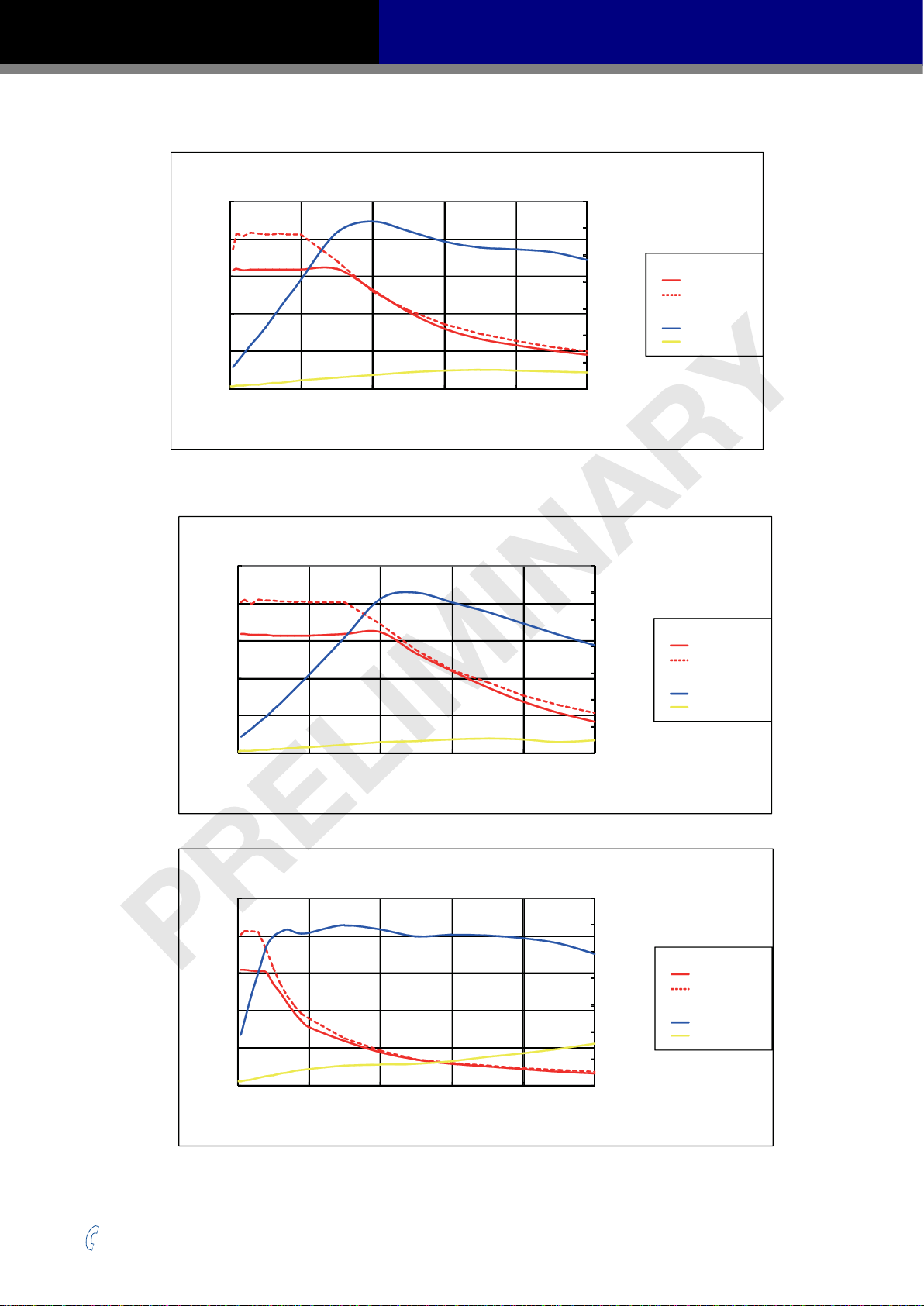
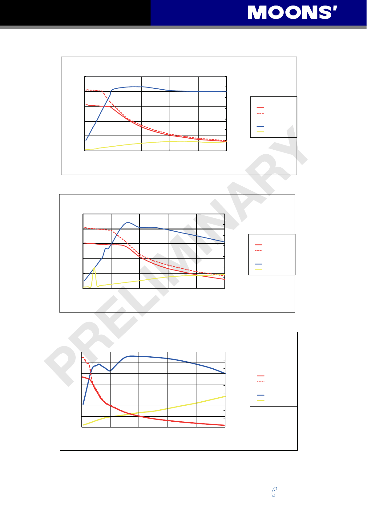
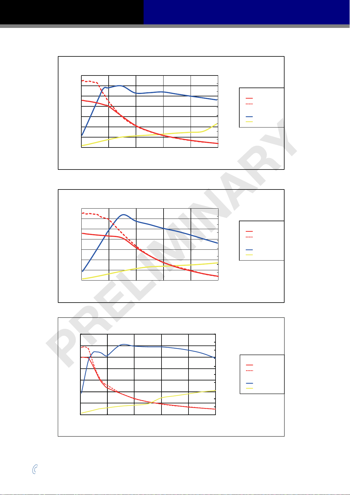
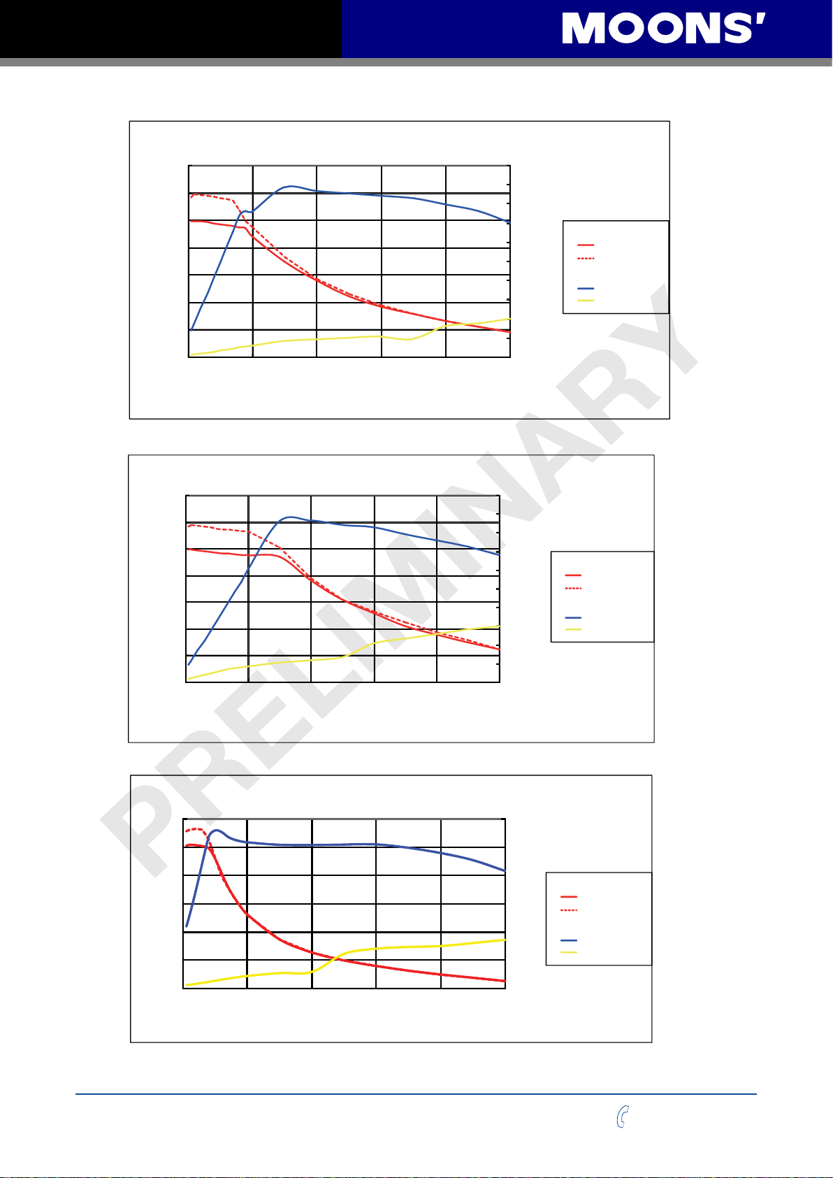
2.7.2 Supply Current
The maximum supply currents required by the SS-EC are shown in the charts below at dierent
power supply voltage inputs. The SS-EC power supply current is lower than the winding currents
because it uses switching ampliers to convert a high voltage and low current into lower voltage and
higher current. The more the power supply voltage exceeds the motor voltage, the less current will
be required from the power supply.
It is important to note that the current draw is signicantly dierent at higher speeds depending on
the torque load to the motor. Estimating how much current is necessary may require a good analysis
of the load the motor will encounter.
Rev. 1.0
2016/7/30
10
+86-400-820-9661
SS03/05/10-EC Hardware Manual
100
AM11SS1DMA 24V Power
80
60
40
Torque(mN.m)
20
0
0 10 20 30 40 50
Speed(RPS)
AM11SS2DMA 24V Power
100
80
60
40
Torque(mN.m)
20
1.2
1.0
0.8
0.6
0.4
0.2
0.0
1.2
1.0
0.8
0.6
0.4
0.2
Torque
Supply Current
Amps
Torque
Supply Current
Amps
Continuous
Boost
Full Load
No Load
Continuous
Boost
Full Load
No Load
0
0 10 20 30 40 50
Speed(RPS)
AM11SS3DMA 24V Power
150
120
90
60
Torque(mN.m)
30
0
0 10 20 30 40 50
Speed(RPS)
0.0
1.2
1.0
0.8
0.6
0.4
0.2
0.0
Torque
Supply Current
Amps
Continuous
Boost
Full Load
No Load
+86-400-820-9661
11
Rev. 1.0
2016/7/30
SS03/05/10-EC Hardware Manual
AM11SS3DMA 24V Power
0.0
0.2
0.4
0.6
0.8
1.0
1.2
0
30
60
90
120
150
0 10 20 30 40 50
Torque(mN.m)
Speed(RPS)
Amps
Continuous
Torque
Boost
Supply Current
Full Load
No Load
AM17SS1DG□-N 24V Power
0.4
0.3
0.2
Torque(N.m)
0.1
1.5
1
0.5
Torque
Supply Current
Amps
Continuous
Boost
Full Load
No Load
0
0 10 20 30 40 50
Speed(RPS)
AM17SS1DG□-N 48V Power
0.4
0.3
0.2
Torque(N.m)
0.1
0
0 10 20 30 40 50
Speed(RPS)
0
1.5
1
0.5
Torque
Supply Current
Amps
Continuous
Boost
Full Load
No Load
0
AM17SS2DG□-N 24V Power
0.6
0.5
0.4
0.3
0.2
Torque(N.m)
0.1
0
0 10 20 30 40 50
Speed(RPS)
Rev. 1.0
2016/7/30
12
1.5
1
0.5
0
Torque
Supply Current
Amps
Continuous
Boost
Full Load
No Load
+86-400-820-9661
SS03/05/10-EC Hardware Manual
0.0
0.2
0.4
0.6
0.8
1.0
1.2
Amps
Continuous
Torque
Boost
Supply Current
Full Load
No Load
AM17SS2DG□-N 48V Power
0.6
0.5
1.5
0.4
0.3
0.2
Torque(N.m)
0.1
0
0 10 20 30 40 50
Speed(RPS)
AM17SS3DG□-N 24V Power
0.7
0.6
0.5
0.4
0.3
0.2
Torque(N.m)
0.1
1
0.5
0
1.5
1
0.5
Torque
Supply Current
Amps
Torque
Supply Current
Amps
Continuous
Boost
Full Load
No Load
Continuous
Boost
Full Load
No Load
0
0 10 20 30 40 50
0.7
0.6
0.5
0.4
0.3
0.2
Torque(N.m)
0.1
0
0 10 20 30 40 50
+86-400-820-9661
Speed(RPS)
AM17SS3DG□-N 48V Power
Speed(RPS)
13
0
1.5
1
0.5
0
Torque
Supply Current
Amps
Continuous
Boost
Full Load
No Load
Rev. 1.0
2016/7/30
SS03/05/10-EC Hardware Manual
1.5
1.2
0.9
0.6
Torque(N.m)
0.3
AM17SS4DG□-N 24V Power
1.5
1
0.5
Torque
Supply Current
Amps
Continuous
Boost
Full Load
No Load
0
0 10 20 30 40 50
Speed(RPS)
AM17SS4DG□-N 48V Power
1.5
1.2
0.9
0.6
Torque(N.m)
0.3
0
0 10 20 30 40 50
Speed(RPS)
0
1.5
1
0.5
0
Torque
Supply Current
Amps
Continuous
Boost
Full Load
No Load
Rev. 1.0
2016/7/30
AM23SS2DG□-N 24V Power
1.5
1.2
0.9
0.6
Torque(N.m)
0.3
0
0 10 20 30 40 50
Speed(RPS)
14
3.5
3
2.5
2
1.5
1
0.5
0
Torque
Continuous
Boost
Supply Current
Amps
Full Load
No Load
+86-400-820-9661
SS03/05/10-EC Hardware Manual
AM23SS2DG□-N 48V Power
1.5
3.5
1.2
0.9
0.6
Torque(N.m)
0.3
0
0 10 20 30 40 50
Speed(RPS)
AM23SS2DG□-N 70V Power
1.5
1.2
0.9
0.6
Torque(N.m)
0.3
3
2.5
2
1.5
1
0.5
0
3.5
3
2.5
2
1.5
1
0.5
Torque
Supply Current
Amps
Torque
Supply Current
Amps
Continuous
Boost
Full Load
No Load
Continuous
Boost
Full Load
No Load
0
0 10 20 30 40 50
Speed(RPS)
AM23SS3DG□-N 24V Power
2.5
2
1.5
1
Torque(N.m)
0.5
0
0 10 20 30 40 50
Speed(RPS)
0
3.5
3
2.5
2
1.5
1
0.5
0
Torque
Supply Current
Amps
Continuous
Boost
Full Load
No Load
+86-400-820-9661
15
Rev. 1.0
2016/7/30
SS03/05/10-EC Hardware Manual
AM23SS3DG□-N 48V Power
2.5
3.5
2
1.5
1
Torque(N.m)
0.5
0
0 10 20 30 40 50
Speed(RPS)
AM23SS3DG□-N 70V Power
2.5
2
1.5
1
Torque(N.m)
0.5
3
2.5
2
1.5
1
0.5
0
3.5
3
2.5
2
1.5
1
0.5
Torque
Supply Current
Amps
Torque
Supply Current
Amps
Continuous
Boost
Full Load
No Load
Continuous
Boost
Full Load
No Load
0
0 10 20 30 40 50
Speed(RPS)
AM23SS4DGA-N 24V Power
3.5
3
2.5
2
1.5
1
Torque(N.m)
0.5
0
0 10 20 30 40 50
Speed(RPS)
0
4.5
4
3.5
3
2.5
2
1.5
1
0.5
0
Torque
Supply Current
Amps
Continuous
Boost
Full Load
No Load
Rev. 1.0
2016/7/30
16
+86-400-820-9661
SS03/05/10-EC Hardware Manual
AM23SS4DGA-N 48V Power
3.5
3
2.5
2
1.5
1
Torque(N.m)
0.5
0
0 10 20 30 40 50
Speed(RPS)
4.5
4
3.5
3
2.5
2
1.5
1
0.5
0
Torque
Supply Current
Amps
Continuous
Boost
Full Load
No Load
AM23SS4DGA-N 70V Power
3.5
3
2.5
2
1.5
1
Torque(N.m)
0.5
0
0 10 20 30 40 50
Speed(RPS)
AM24SS3DG□-N 24V Power
3.5
3
2.5
2
1.5
Torque(N.m)
1
0.5
0
0 10 20 30 40 50
Speed(RPS)
5
4.5
4
3.5
3
2.5
2
1.5
1
0.5
0
4.5
4
3.5
3
2.5
2
1.5
1
0.5
0
Torque
Supply Current
Amps
Torque
Supply Current
Amps
Continuous
Boost
Full Load
No Load
Continuous
Boost
Full Load
No Load
+86-400-820-9661
17
Rev. 1.0
2016/7/30
SS03/05/10-EC Hardware Manual
AM24SS3DG□-N 48V Power
3.5
3
2.5
2
1.5
Torque(N.m)
1
0.5
0
0 10 20 30 40 50
Speed(RPS)
5
4.5
4
3.5
3
2.5
2
1.5
1
0.5
0
Torque
Supply Current
Amps
Continuous
Boost
Full Load
No Load
AM24SS3DG□-N 70V Power
3.5
3
2.5
2
1.5
Torque(N.m)
1
0.5
0
0 10 20 30 40 50
Speed(RPS)
AM34SS1DGA-N 24V Power
3
2.5
2
1.5
1
Torque(N.m)
0.5
5
4.5
4
3.5
3
2.5
2
1.5
1
0.5
0
Torque
Continuous
Boost
Supply Current
Amps
Full Load
No Load
6
5
4
Torque
3
Amps
2
1
Continuous
Boost
Supply Current
Full Load
No Load
Rev. 1.0
2016/7/30
0
0 10 20 30 40 50
Speed(RPS)
18
0
+86-400-820-9661

SS03/05/10-EC Hardware Manual
AM34SS1DGA-N 48V Power
3
6
2.5
2
1.5
1
Torque(N.m)
0.5
0
0 10 20 30 40 50
Speed(RPS)
AM34SS1DGA-N 70V Power
3
2.5
2
1.5
1
Torque(N.m)
0.5
5
4
Torque
3
Amps
2
1
Continuous
Boost
Supply Current
Full Load
No Load
0
6
5
4
Torque
3
Amps
2
1
Continuous
Boost
Supply Current
Full Load
No Load
0
0 10 20 30 40 50
Speed(RPS)
AM34SS3DGA-N 24V Power
6
5
4
3
2
Torque(N.m)
1
0
0 10 20 30 40 50
Speed(RPS)
0
6
5
4
Torque
3
Amps
2
1
Continuous
Boost
Supply Current
Full Load
No Load
0
+86-400-820-9661
19
Rev. 1.0
2016/7/30

SS03/05/10-EC Hardware Manual
AM34SS3DGA-N 48V Power
6
6
5
4
3
2
Torque(N.m)
1
0
0 10 20 30 40 50
Speed(RPS)
AM34SS3DGA-N 70V Power
6
5
4
3
2
Torque(N.m)
1
5
4
3
2
1
Torque
Supply Current
Amps
Continuous
Boost
Full Load
No Load
0
6
5
4
Torque
3
Amps
2
1
Continuous
Boost
Supply Current
Full Load
No Load
0
0 10 20 30 40 50
Speed(RPS)
AM34SS5DGA-N 24V Power
10
8
6
4
Torque(N.m)
2
0
0 10 20 30 40 50
Speed(RPS)
0
6
5
4
Torque
3
Amps
2
1
Continuous
Boost
Supply Current
Full Load
No Load
0
Rev. 1.0
2016/7/30
20
+86-400-820-9661

SS03/05/10-EC Hardware Manual
AM34SS5DGA-N 48V Power
10
6
8
6
4
Torque(N.m)
2
0
0 10 20 30 40 50
Speed(RPS)
AM34SS5DGA-N 70V Power
10
8
6
4
Torque(N.m)
2
5
4
3
2
Torque
Supply Current
Amps
Continuous
Boost
Full Load
No Load
1
0
5
4
3
2
1
Torque
Supply Current
Amps
Continuous
Boost
Full Load
No Load
0
0 10 20 30 40 50
Speed(RPS)
0
+86-400-820-9661
21
Rev. 1.0
2016/7/30

SS03/05/10-EC Hardware Manual
2.7.3 Auxiliary Supply Voltage (Keep Alive Function)
In addition to the main power supply input, the SS-EC also has an auxiliary power input (AUX
power) for Keep Alive function of the drive. When the main power supply is o, the AUX power will
keep the logic power on, allowing the drive to remember its state data (motor position, etc.). This
allows the motor to resume operation from its previous position without a homing routine when the
main power is switched back on.
If the main power is removed while the auxiliary power is still on and the drive is disabled, the drive
will show a warning. The LED display will read
power is restored, the drive will automatically clear the warning.
If the main power is removed while the auxiliary power is still on and the drive is enabled, the drive
will show a fault. The LED display will read
When the main power is restored, the drive will not automatically clear the fault. It will need to be
cleared by either the I/O alarm reset function or a clear fault command from the master controller.
2.7.3.1 Keep Alive Recovery with I/O Function
After the main power supply has been restored, the fault must be cleared. Use the alarm reset
function through input 6 (X6) if congured for alarm reset function. (See Section 3.1.2 for conguring
this input via the Step-Servo Quick Tuner software.) When an internal voltage out of range alarm
occurs, the motor is disabled. Use the servo on function through input 5 (X5), also congurable via
the software, to re-enable it.
indicating under voltage. When the main
indicating the internal voltage is out of range.
Resume motion and normal program operation.
2.7.3.2 Keep Alive Recovery with the Master Controller
After the main power supply has been restored, the fault must be cleared. The master controller
program can write 0x80 to Control Word (0x6040) to clear the fault. When an internal voltage out of
range alarm occurs, the motor is disabled. The master controller program can write 0x0F to Control
Word (0x6040) to enable the motor.
Resume motion and normal program operation.
Rev. 1.0
2016/7/30
22
+86-400-820-9661

SS03/05/10-EC Hardware Manual
P2
2.8 Connecting the Motor
The SS motors have two cables - the motor power cable, and the encoder feedback cable. Use
the optional motor extension cable and/or encoder extension cable, or make extension cables
using connector housing and crimps included in package if more length is needed. Connect the
motor power cable’s black, green, red and blue wires respectively to the drive’s A+, A-, B+ and B-
connections. Plug the encoder feedback cable into the encoder feedback connector on the drive.
DO NOT drag the motor by the cables as this may damage it.
Wire Colors
B
B
A
A
-
+
-
+
Blue
Red
Green
Black
Motor Connector
CN1
2
A-
4
B-
6
Z-
U-
V-
W-
8
10
12
14
16
GND
Encoder Feedback Connector
See Section 6 ”Optional Accessories (Sold Separately)” for cables and mating connectors.
11
13
15
1
3
5
7
9
A+
B+
Z+
+5V
NC
U+
V+
W+
+86-400-820-9661
23
Rev. 1.0
2016/7/30

SS03/05/10-EC Hardware Manual
2.9 Connecting the EtherCAT
Dual RJ-45 connectors (connection CN3) accept standard Ethernet cables and are categorized
as 100BASE-TX (100 Mb/sec) ports. CAT5 or CAT5e (or higher) cables should be used. The IN
port connects to a master, or to the OUT port of an upstream node. The OUT port connects to a
downstream node. If the drive is the last node on a network, only the IN port is used. No terminator
is required on the OUT port.
2.9.1 EtherCAT Status Indicator LEDs
The LEDs are used for indicating status of the EtherCAT. There are two Link/Activity LEDs (one for
each RJ-45 Ethernet connector) and two status LEDs (RUN and ERR).
Link/Activity Link/Activity
LED indicator codes:
LED Color Status Description
Link/Activity Green
RUN Green
ERR Red
ERR
OFF no Ethernet connection
ON Ethernet is connected
Flickering activity on line
OFF initialization state
Blinking pre-operational state
Single Flash safe-operational state
ON operational state
OFF no error
Blinking general error
Single Flash sync error
Double Flash watch dog error
RUN
Notes:
• Flickering: Rapid ashing with a period of approximately 50ms (10Hz)
• Blinking: Flashing with equal on and o periods of 200ms (2.5Hz)
• Single Flash: Repeating on for 200ms and o for 1s
• Double Flash: Two ashes with a period of 200ms followed by o for 1s
Rev. 1.0
2016/7/30
24
+86-400-820-9661

SS03/05/10-EC Hardware Manual
2.10 Connecting the STO
On the SS EtherCAT step-servo drives, the STO (Safe Torque O) function is connected via port
CN4. The STO function shuts o the motor’s current turning o the motor output torque by forcibly
turning o the signal of the drive’s power transistor. This is done internally through the STO Input/
Output signal circuit.
2.10.1 Safety Precautions
• If you want to bypass the STO function, make sure the STO connector is plugged into CN4 on
the drive correctly.
• When using the STO function, perform an equipment risk assessment to ensure that the system
conforms to the safety requirements.
• Even when the STO function is enabled, the motor may move due to external force (e.g.
gravitational force on the vertical axis). Make sure a holding brake is used in applications where
this is possible.
• When the STO function engages and the torque is removed, the motor will be “free running”,
requiring more distance until the motion stops. Make sure this will not be a safety issue.
• When the STO function operates, it will turn o the current to the motor, but it does not turn o
the power to the drive. Make sure to disconnect the power to the drive before performing any
maintenance on it.
• After the STO function is triggered, the drive will have a fault alarm status, and the motor will
remain disabled even after the STO function switch is plugged back in. To restore the system to
normal operation, clear the fault alarm, and then enable the drive and motor.
2.10.2 STO Internal Circuit Diagram
SF1+
1.5K
SF1-
1.5K
SF2+
SF2-
EDM+
EDM-
2.10.3 CN4 Connector diagram
+86-400-820-9661
25
Rev. 1.0
2016/7/30

SS03/05/10-EC Hardware Manual
2.10.4 STO Signal Denition
Signal Symbol Pin Description Control Mode
SF1+ 1
Safety Input SF1
SF1- 2
SF2+ 3
Safety Input SF2
SF2- 5
EDM+ 6
Safety Output
EDM- 4
When SF1 has no input signal, e.g.
the port is disconnected, SF1 will be
considered OFF. The upper half of the
internal power transistor will be shut o.
When SF2 has no signal input, e.g.
the port is disconnected, SF2 will be
considered OFF. The upper half of the
internal power transistor will be shut o.
Output monitor signal used to check the
safety function
Ground DGND 7, 8 +5VDC power ground
+5V power +5V 9, 10 +5VDC power supply
2.10.5 STO Connection Diagrams
Connection to safety switch
24VDC
Safety Switch
Safety Input 1
SS EtherCAT Drive
SF1+
SF1-
SF2+
Compatible with all
control modes
Safety Input 2
EDM+
Safety Output
EDM-
0VDC
Safety light connection
Safety Output
SF2-
SS EtherCAT Drive
Rev. 1.0
2016/7/30
26
+86-400-820-9661

SS03/05/10-EC Hardware Manual
3 Inputs and Outputs
The SS-EC drive’s inputs and outputs include:
• 8 optically isolated digital inputs, 5-24VDC high level voltage
• 4 optically isolated digital outputs, max 30V/100mA sink or source current
• 2 analog inputs, can be congured to 0-5V, 0-10V, ±5V or ±10V signal ranges.
• Dierential encoder signal output (AOUT +/-, BOUT +/-, ZOUT +/-), 26C31 line driver, 20mA sink
or source current
CN5
X1X2X3X4-
X6
X8
XCOM
+5V
AIN2
Y1Y2Y3-
Y4AOUTBOUT-
ZOUT-
2
4
6
8
10
12
14
16
18
20
22
24
26
28
30
32
1
3
5
7
9
11
13
15
17
19
21
23
25
27
29
31
X1+
X2+
X3+
X4+
X5
X7
GND
AIN1
Y1+
Y2+
Y3+
Y4+
AOUT+
BOUT+
ZOUT+
I/O Connector
+86-400-820-9661
27
Rev. 1.0
2016/7/30

SS03/05/10-EC Hardware Manual
3.1 Digital Inputs
3.1.1 X1, X2, X3 and X4 Digital Inputs
X1, X2, X3 and X4: optically isolated, dierential, 5-24VDC, minimum pulse width 250ns, maximum
pulse frequency 2MHz
• X1 can be used as general purpose input.
• X2 can be used as general purpose input.
• X3 can be used as CW limit input or general purpose input.
• X4 can be used as CCW limit input or general purpose input.
Use Step-ServoQuickTuner software for X1, X2, X3 and X4 function conguration.
The following graphs show some common connection methods for the inputs:
X1/2/3/4+
SS-EC
Drive
X1/2/3/4-
5-24
VDC
Power
Supply
+
Switch or Relay
(closed = logic Low)
-
Connecting the inputs to a switch or relay
5-24
VDC
Power
Supply
+
+
NPN
Output
-
output
–
X1/2/3/4+
X1/2/3/4-
SS-EC
Drive
Connecting the inputs to an NPN type output
Rev. 1.0
2016/7/30
5-24
VDC
Power
Supply
+
-
+
PNP
Output
–
output
X1/2/3/4+
X1/2/3/4-
SS-EC
Drive
Connecting the inputs to a PNP type output
28
+86-400-820-9661

SS03/05/10-EC Hardware Manual
3.1.2 X5, X6, X7 and X8 Digital Inputs
X5, X6, X7 and X8: optically isolated, single-ended, 5-24VDC, minimum pulse width 50μs, maximum
pulse frequency 10KHz
• X5 can be used as servo on input or general purpose input.
• X6 can be used as alarm reset input or general purpose input.
• X7 can be used as general purpose input.
• X8 can be used as general purpose input.
Because the input is an optically isolated circuit, a 5-24V power supply is needed. For example, you
can use the power supply of the PLC when you are using a PLC control system, but if you want to
connect a relay or mechanical switch to the input , you must need a power supply.
XCOM is an electronics term for a single-ended signal connection to a common voltage. In the case
of SS series, if you are using a sourcing (PNP) input signals, you need to connect XCOM to the
ground (power supply -), if you are using a sinking(NPN) input signals ,the XCOM need to connect
to the power supply +.
Use Step-ServoQuickTuner software for X5, X6, X7 and X8 function conguration.
The following graphs show some common connection methods for the inputs:
5-24
VDC
Power
Supply
+
Switch or Relay
(Closed: logic low)
-
XCOM
SS-EC
Drive
X5/X6/X7/X8
Connecting to a switch or relay
XCOM+
5-24
VDC
Power
Supply
+
NPN
Type
Output
-
output
-
X5/X6/X7/X8
SS-EC
Drive
Connecting an NPN type output to an input
+86-400-820-9661
output
5-24
VDC
Power
Supply
+
+
PNP
Type
Output
-
-
Connecting a PNP type output to an input
29
X5/X6/X7/X8
SS-EC
Drive
XCOM
Rev. 1.0
2016/7/30

SS03/05/10-EC Hardware Manual
3.2 Y1, Y2, Y3 and Y4 Digital Outputs
• Y1 can be used as an alarm signal output. It can also be used as a static in position signal
output (static, checking in position when the motor is stopped), or as a dynamic in position signal
output (dynamic, checking in position all the time).
• Y2 can be used as a tach signal output. Tach output produces pulses relative to the motor
position with congurable resolution. It can also be used as a static in position signal output
(static, checking in position when the motor is stopped), or as dynamic in position signal output
(dynamic, checking in position all the time), or as a timing signal output (50 pulses per rotation).
• Y3 can be used as a signal output to release a brake. It can also be used as a static in position
signal output (static, checking in position when the motor is stopped), or as a dynamic in position
signal output (dynamic, checking in position all the time).
• Y4 can be used as a static in position signal output (static, checking in position when the motor
is stopped), or as a dynamic in position signal output (dynamic, checking in position all the time).
Use Step-ServoQuickTuner software for Y1, Y2, Y3 and Y4 function conguration.
The following graphs show some common connection methods for the outputs:
NOTE: Do not connect the outputs to more than 30VDC power supply. And the
current of each output terminal must not exceed 100mA.
5-24 VDC
Power Supply
+ –
Y1/2/3/4+
Load
SS-EC
Drive
Y1/2/3/4-
Connecting a sinking output
5-24 VDC
Power Supply
+
–
Y1/2/3/4+
SS-EC
Drive
Y1/2/3/4-
COM
PLC
IN
Rev. 1.0
2016/7/30
Connecting a sinking output to a PLC’s input
30
+86-400-820-9661

SS03/05/10-EC Hardware Manual
Connecting a sinking output
Connecting a sinking output to a PLC’s input
SS-EC
Drive
5-24 VDC
Power Supply
+ –
Load
Y1/2/3/4-
Y1/2/3/4-
Y1/2/3/4+
Y1/2/3/4+
PLC
5-24 VDC
Power Supply
+
–
COM
IN
SS-EC
Drive
CDV 42-5
Power Supply
+ –
Y1/2/3/4+
SS-EC
Drive
Y1/2/3/4-
Connecting a sourcing output to a PLC’s input
Y1/2/3/4+
SS-EC
3.3 Analog Inputs
The SS series drive has two analog signal inputs which can accept signal range of 0-5V, 0-10V,
±5V or ±10V. The drive can be congured to operate at velocity mode or position mode that is
proportional to the analog input.
Drive
Y1/2/3/4-
COM
IN
5-24 VDC
relay
Power Supply
+ –
1N4935 suppression diode
Driving a relay
PLC
Use Step-ServoQuickTuner software to congure the input range, oset, deadband and noise
lter frequency.
The SS series provides a +5V, 100mA limit power supply that can be used to power external
devices such as potentiometer. For more precise readings use an external supply that can provide
the desired accuracy.
+5v OUT
1 - 10k
pot
Ω
AIN
GND
SS-EC
Drive
Connecting a Potentiometer to an analog input
+86-400-820-9661
31
Rev. 1.0
2016/7/30

SS03/05/10-EC Hardware Manual
3.4 Encoder output
The SS-EC drive has dierential encoder outputs (AOUT+, AOUT-, BOUT+, BOUT-, ZOUT+,
ZOUT-), with 26C31 line driver, 20 mA sink or source current max. These signals can be connected
to the motion controller to provide feedback of the motor position.
SS-EC
AOUT+
AOUT-
BOUT+
BOUT-
ZOUT+
ZOUT-
GND GND
A+
A-
B+
B-
Z+
Z-
Host Controller
Rev. 1.0
2016/7/30
32
+86-400-820-9661

SS03/05/10-EC Hardware Manual
4 Control Panel (LED display and keys)
4.1 Description of Control Panel
LED Display
Mode Key
M
Up Key
Symbol Name Details
LED Display
MODE Button
UP/DOWN Button
SET Button
The LED display (5 digits, 7 segments) show the drive’s operating
condition and warning codes, parameters and settings values.
Press and hold the MODE button to change the LED display mode
a) Monitoring selection mode
b) Function selection mode
c) Parameter setting mode
When editing the parameters, press the MODE button to move the cursor
to the left and then change the parameters by using the arrow keys.
Press the UP or DOWN button to scroll through and change monitor codes,
parameter groups and various parameter settings.
Press to enter a mode
Press and hold to save parameters/settings
Set Key
S
Down Key
4.2 Mode Switch Control
(1) Press the button and the button to change modes between status monitoring,
function control, parameter setting, etc.
(2) If no warnings or faults have occurred, the drive will not go into warning and fault display mode.
(3) If any warnings are detected by the drive, the LED display will immediately switch into warning
or fault display mode. Pressing any key will switch back to the previous display mode.
(4) When no button(s) on the control panel has been pressed for 20 seconds, the display will
switch back to the previous status monitoring display mode.
(5) In monitoring selection mode, function selection mode and parameter setting mode, when
editing the parameters, press
using the
buttons.
(6) In status monitoring mode, press and hold the
the panel, press and hold the button again.
to move the cursor to the left, then change the parameters by
button to lock the control panel. To unlock
+86-400-820-9661
33
Rev. 1.0
2016/7/30

SS03/05/10-EC Hardware Manual
the SET key to confirm setting value
Control mode switch owchart:
Power On
Monitor Status
In factory default mode, it will display motor’s rotatory velocity.(*NOTE 1)
The last dot shows whether the drive is enable or disable.
Press and hold the
MODE key for 1 second
M
key for 1 second(*NOTE 4)
Press any key
Monitor Parameters
Press and hold the
MODE key for 1 second
M
Function Parameters
Press and hold the MODE
M
Drive Parameters
Configuration
Press the UP and
DOWN key to scroll
through and change
monitor status
Press the UP and
DOWN key to scroll
through and change
function selection
Press the UP and
DOWN key to scroll
through and change
parameter selection.
Press SET key back
to Monitor Status
S
Press and hold SET key to
confirm selection and execute it.
S
Press SET key enter
to value setting mode
S
Press SET key back to
Drive Parameters Configuration
mode without changing.
*NOTE(2)
Press and hold for 1 second
*Note(3)
S
NOTE:
(1) When power is applied, the drive’s display will show the customer dened monitoring
mode. In factory default mode, it will display motor’s rotary velocity.
(2) In parameter setting mode, press the
button to exit the parameter setting mode and
return to the parameter selection mode, any changes will not be saved.
(3) In parameter setting mode, press and hold the
button to conrm and apply the
current parameter setting. This will take eect immediately. However, this change will not
save to the drive’s ash. If this parameter is required for permanent use, go to function mode
“
”, and then press and hold the button to save the parameter change.
(4) When the drive is connected to the host computer with Step-Servo Quick Tuner on, the
parameter setting mode CANNOT be accessed directly on the drive’s control panel.
Rev. 1.0
2016/7/30
34
+86-400-820-9661

SS03/05/10-EC Hardware Manual
4.3 LED display description
4.3.1 Decimal Point And Negative Sign Description
LED display Description
Negative sign: when the value to be
displayed is a negative number ≥-9999,the
highest digit will display as a negative sign.
negative
sign
motor enable
sign
4.3.2 Parameter View Setting
LED display Description
4.3.3 Parameter Save Setting
LED display Description
Decimal point: when the value to be displayed
is a negative number ≤-10000, a decimal
point will be displayed.
There are only 5 digits on the LED display, when a value with
more than 5 digits needs to be displayed, it will be shown in 2
segments. When the highest digit of a value is ashing, it means
only the lower 5 digits are shown. Press
upper 5 digits.
The graph is showing ‘-12802345’
In parameter setting mode, pressing and holding the button
will save the change. ‘Saved’ will also be displayed on the LED.
In parameter setting mode when the motor is rotating, pressing
to display the
4.3.4 Point To Point Motion Mode
LED display Description
+86-400-820-9661
and holding the
the status as “busy” meaning that the current parameter cannot
be saved. Stop the motion of the motor and save the parameter
again.
When the LED display reads “P-CW” it means the motor is
rotating in a CW direction in the point-to-point mode
When the LED display reads “P-CCW” it means the motor is
rotating in a CCW direction in the point-to-point mode
35
button will cause the LED display to show
Rev. 1.0
2016/7/30

SS03/05/10-EC Hardware Manual
4.3.5 Jog Mode
LED display Description
4.3.6 Control Panel Lock
LED display Description
When the LED display reads “J--CW” it means the motor is
rotating in a CW direction in JOG mode.
When the LED display reads “J--CCW” it means the motor is
rotating in a CCW direction in JOG mode
This means the key panel is locked. Press and hold for 1
second while in status monitoring mode to lock it.
When the control panel is locked, press and hold for 1
second to unlock it.
4.4 Status Monitoring Selection Mode
To change the status monitoring type, press to enter monitoring selection mode, and then use
to make selections, and press to conrm. Steps are shown as follows:
Power ON
Default display is current motor velocity
The last decimal point is drive enable sign
Stats Display
Press Any Key
Status Monitoring
Selection
Press UP and
DOWN key
to select display
detail.
Press SET key to
select display mode
S
Rev. 1.0
2016/7/30
36
+86-400-820-9661

SS03/05/10-EC Hardware Manual
N mode selection and setting LED display Description Unit
n-00
n-01
n-02
n-03
n-04
n-05
n-06
n-07
n-08
n-09
Motor Rotation Speed RPM
Position Error counts
Pulse Counter counts
Encoder Counter counts
Command Position Counter counts
Drive Temperature x 0.1°C
DC Bus Voltage x 0.1V
SCL Address
Alarm History 1
Alarm History 2
n-10
n-11
n-12
n-13
n-14
n-15
Alarm History 3
Alarm History 4
Alarm History 5
Alarm History 6
Alarm History 7
Alarm History 8
+86-400-820-9661
37
Rev. 1.0
2016/7/30

SS03/05/10-EC Hardware Manual
4.5 Function Control Mode
In function control mode (display reads: F+parameter number), you can select functions for
preoperational mode, restart the drive, enable or disable the drive, etc. In status monitoring mode,
press and hold
for 1 second to enter function control mode. Press to select a
function, and then press and hold
F-01(CJ) excepted)
Status display
selection
Press and Hold MODE key
for 1 second
M
Function Mode
Selection
4.5.1 Function Mode Description
Function mode details are as follows:
to conrm or execute the function. (NOTE: F-00(FL) and
Press UP and
DOWN key
to select display detail.
Press and Hold Set key to
select and execute the function
S
Function mode
number
LED display Description
F-00 point to point position mode:1rps, 1rev
F-01
F-02
F-03
F-04
F-05
F-06
F-07
JOG mode:JOG speed 1rps
Restart the drive
Clear drive’s current alarm
Save parameter changes for Pxx
Motor disable
Motor enable
Activate the analog “auto oset” algorithm
F-08
Rev. 1.0
2016/7/30
Stop move and remove buered command
38
+86-400-820-9661

SS03/05/10-EC Hardware Manual
4.5.2 Operation Flow Chart
status monitoring
selection
press and hold MODE key
for 1 second
M
function selection
mode
Press UP and DOWN key
to select display detail.
F-00 point to point mode
F-01 JOG mode
Press UP and DOWN key
to select display detail.
F-02 Restart the drive
press and hold
SET key
press M key
press and hold
SET key
S
M
press M key
press and hold
SET key
press ,motor rotate
1 rev in CW direction
press ,motor rotate
1 rev in CCW direction
press to stop the motor
S
press to return back
M
NOTE: In P-P mode, rotary velocity is 1rps,
and 1 rev per time.
press ,motor rotate
in CW direction
Press ,motor rotate
in CCW direction
press stop motor
S
press to return back
M
NOTE: In JOG mode, rotary velocity is
1rps
Drive restart, and back to status
monitoring mode
Press UP and DOWN key
to select display detail.
F-03 Alarm clear
Press UP and DOWN key
to select display detail.
F-04 save parameter
Press UP and DOWN key
to select display detail.
F-05 motor disable
Press UP and DOWN key
to select display detail.
F-06 motor enable
Press UP and DOWN key
to select display detail.
S
press and hold
SET key
S
press and hold
SET key
S
display after
1 second
press and hold
SET key
S
press and hold
SET key
S
clear current drive warning
To save parameter changes for P-00
to P-98 permanently.
To disable the drive
If no alarm has occurred, enable the
drive immediately
SAVE means
success operation.
+86-400-820-9661
F-07 Analog Input Auto-offset
Press UP and DOWN key
to select display detail.
F-08 Stop move and remove
buffered command
39
press SET key
S
press SET key
S
Analog Input Auto-offset
Stop move and remove buffered
command
Rev. 1.0
2016/7/30

SS03/05/10-EC Hardware Manual
4.6 Parameter Setting Mode
4.6.1 Parameter Setting Description
The parameter setting mode (P+parameter number) allows you to select, display and edit the
necessary parameter. In function control mode, press and hold
parameter setting mode. Use
or edit the parameter. Press
to select the required parameter, and press to view
again to quit and no change will be saved. Press and hold
for 1 second to enter
for 1 second to save the parameter change. However this change will NOT be saved at the next
power on. To save the parameter PERMANENTLY, go into function control mode (F+parameter
number), and use F-04SA function.
function selection
mode
press and hold MODE key
for 1 second
M
parameter setting
selection
Press UP and DOWN key
to select display detail.
press SET key to
enter parameter editing mode
S
short press SET key
to quit
press and hold SET key
to save parameter change
S
Rev. 1.0
2016/7/30
40
+86-400-820-9661

SS03/05/10-EC Hardware Manual
4.6.2 Parameter Editing Examples
M
First digit flash
Press
Press up or down to increase or decrease value
Press
Press mode to
shift flashing digit
Press
Second digit flashing
Press
Press SET key to
enter parameter editing mode
S
M
Second digit flashing
Press
press UP or DOWN to increase or decrease value press UP or DOWN to increase or decrease value
Press
Press mode to
shift flashing digit
Press
First digit
Press
Press and hold set key
to save parameter
S
The parameter change is only saved for current
operation, it will back to original after next power up
Set display for 1 second, means save successfully
M
Press and hold mode key
Function mode selection
Press up and down key
to select display detail.
F-04 to save
parameter
Setafter 1 second
return to parameter
selection page
Press and hold set key
S
Save parameter
Saved display for 1 second
and return back to previous
page
Saved means
operation successful
+86-400-820-9661
41
Rev. 1.0
2016/7/30

SS03/05/10-EC Hardware Manual
4.6.3 Parameter list
Refer to the HostCommandReference for command details.
Parameter
Number
P00 KP position loop proportional gain
P01 KD
P02 KE
P03 VP
P04 VI
P05 -
P06 KK
P07 KC
P08 SF
P09 CM
P10 -
P11 PM
P12 JM
SCL Command
LED
Display
Function
position loop dierential gain
dierential lter
velocity loop proportional gain
velocity loop integrator gain
reserved
inertia feedforward gain
overall lter
step smoothing lter frequency
command mode
reserved
power up mode
jog mode
P13 GC
P14 CC
P15 CP
P16 -
P17 HC
P18 -
P19 VM
P20 AM
P21 JS
P22 JA
P23 JL
P24 VE
P25 AC
P26 DE
current command (torque mode)
continuous current
peak current
reserved
hard stop current
reserved
maximum velocity
maximum acceleration
jog speed
jog acceleration
jog deceleration
velocity
acceleration
deceleration
Rev. 1.0
2016/7/30
P27 VC
P28 JC
42
velocity change
velocity mode second speed
+86-400-820-9661

SS03/05/10-EC Hardware Manual
P29 - reserved
P30 -
P31 -
P32 -
P33 -
P34 -
P35 -
P36 ER
P37 -
P38 EG
P39 SZ
P40 PF
P41 PL
P42 PD
P43 PE
reserved
reserved
reserved
reserved
reserved
reserved
encoder resolution
reserved
electronic gearing
pulse mode setting
position fault limit
position limit for dynamic in position
position limit for static in position
in position timing
P44 TT
P45 AP
P46 AG
P47 AN
P48 -
P49 -
P50 AV
P51 AS
P52 -
P53 -
P54 AD
P55 AF
P56 AT
P57 SI
pulse complete timing
analog position gain
analog velocity gain
analog torque gain
reserved
reserved
analog oset value
analog scaling
reserved
reserved
analog deadband
analog lter
analog threshold
enable input usage
P58 AI
P59 DL
P60 AO
+86-400-820-9661
43
alarm reset input usage
dene limit
alarm output
Rev. 1.0
2016/7/30

SS03/05/10-EC Hardware Manual
P61 BO brake output
P62 MO
P63 BD
P64 BE
P65 FI
P66 FI
P67 FI
P68 FI
P69 -
P70 -
P71 IF
P72 PR
P73 TD
P74 BR
P75 -
motion output
brake disengage delay
brake engage delay
lter input for X5
lter input for X6
lter input for X7
lter input for X8
reserved
reserved
immediate format
protocol
transmit delay
baud rate
reserved
P76 CO
P77 -
P78 PK
P79 DD
P80 MA
P81 ZT
node id
reserved
parameter lock on control panel
default display item of LEDs
for advanced user only, not recommended
regen resistor peak time
Rev. 1.0
2016/7/30
44
+86-400-820-9661

SS03/05/10-EC Hardware Manual
4.7 Control Panel Lock
In order to prevent unauthorized or unintentional use of the key panel, a key panel lock is available
on all SS-EC drives. When the lock feature is on, no function can be changed directly on drive’s
control panel.
Status monitoring
Press and hold set key
for 1 second
If control panel is locked,
press any key will show lck
In control parameter lock mode,
press and hold set key
for 1 second will unlock
Unlock display
4.8 Warning And Fault Display
If any of the following warnings are detected by the drive when power is applied, the LED display
on the drive will immediately switch into warning or fault display mode.
If more than one warning is detected, you can scroll through by pressing the
Press
or to clear the warning display and return to the previous display mode.
Any Mode
Warning or fault alarm occurs
Bad Encoder
buttons.
Open Winding
+86-400-820-9661
If more than 1 alarm has occurred,
press Up or Down key to scroll through
the alarms
S
M
Press Set and Mode key
to exit alarm display mode
45
Previous Monitoring Mode
Rev. 1.0
2016/7/30

SS03/05/10-EC Hardware Manual
LED display Description
DriveOverTemperature
InternalVoltageBad
OverVoltage
HighsideOverCurrent
LowsideOverCurrent
OverCurrentReading
BadEncoder
OpenWinding
PositionLimit
Under Voltage
CCW Limit and CW Limit
CCW Limit
CW Limit
Current Foldback
Communication Error
Save Failed
STOActivated
RegenFailed
Blank Q Segment
Move while Disabled
NOTE: Items in bolditalic represent Drive Faults, which automatically disable the motor.
Rev. 1.0
2016/7/30
46
+86-400-820-9661

SS03/05/10-EC Hardware Manual
4.9 LED Character Reference
1 2 3 4 5 6 7 8 9 10
A B C D E F G H I J
K L M N O P Q R S T
U V W X Y Z
+86-400-820-9661
47
Rev. 1.0
2016/7/30

SS03/05/10-EC Hardware Manual
Unit:mm
5 Reference Materials
5.1 Drive Mechanical Outlines
41
150
28.5
5
139.5
R2.5
956.5
6
5
Rev. 1.0
2016/7/30
48
+86-400-820-9661

SS03/05/10-EC Hardware Manual
5.2 Drive Technical Specications
Power Amplier
Amplier Type Dual H-Bridge, 4 Quadrant
Current Control 4 state PWM at 20 KHz
SS03 Maximum continuous current 3A, boost current 4.5A (for 1.5s)
Drive auto-sets the current limitation according to the attached motor
Output Current
Power Supply
Auxiliary Power Supply External 12 - 48 volt DC power supply required
Protection Over-voltage, under-voltage, over-temp, over-current, short circuit
Microstep Resolution Software selectable from 200 to 51200 steps/rev in increments of 2 steps/rev
Encoder Resolution 20000 counts/rev for AM17/23/24/34SS motor; 4096 counts/rev for AM11SS motor
Speed Range Speeds up to 3600 rpm
Filters
Non-Volatile Storage Congurations are saved in FLASH memory on-board the DSP
Supported Protocol CoE (CiA 402 Drive prole)
Supported Modes
Synchronization SM Event, DC Sync Event
SS05 Maximum continuous current 5A, boost current 7.5A (for 1.5s)
Drive auto-sets the current limitation according to the attached motor
SS10 Maximum continuous current 10A, boost current 15A (for 1.5s)
Drive auto-sets the current limitation according to the attached motor
External 24 - 70 volt DC power supply required
Absolute maximum input voltage range 18 - 75 VDC
Controller
Programmable hardware digital noise lter, software noise lter, smoothing lter, PID lter, notch lter
Prole Position, Prole Velocity, Prole Torque, Cyclic Synchronous Position, Cyclic Synchronous
Velocity, Homing, and MOONS’ own Q mode
X1, X2, X3, X4: optically isolated, dierential, 5-24VDC, minimum pulse width 250ns,
Digital Inputs
Digital Output
Analog Input
+5V Supply Output +4.8 - 5 volts @ 100mA maximum
Communication EtherCAT and mini USB for conguration
maximum pulse frequency 2MHz
X5, X6, X7, X8: optically isolated, single-ended input, 5-24VDC
Y1, Y2, Y3, Y4: optically isolated, open collector, 30 volts, 100 mA max, maximum pulse frequency
10 KHz
AIN1, AIN2: individually single-ended or together dierential, input resolution 12-bit, software
congured as 0-5 volts, 0-10 volts, ±5 volts or ±10 volts (AIN referenced to GND)
Environment
Ambient Temperature 0 - 40°C (32 - 104°F) when mounted to a suitable heatsink
Humidity 90% non-condensing
+86-400-820-9661
49
Rev. 1.0
2016/7/30

SS03/05/10-EC Hardware Manual
5.3 Recommended Motors and Specications
Motor Part
Number
AM11SS1DMA
AM11SS2DMA 0.08 12 168
AM11SS3DMA 0.125 18 218
AM17SS1DG□-N
AM17SS2DG□-N 0.5 57 440
AM17SS3DG□-N 0.6 82 520
AM17SS4DG□-N 0.75 123 760
AM23SS2DG□-N
AM23SS4DGA-N 2.5 365 840
AM24SS3DG□-N
AM34SS1DGA-N 3.5 915 2000
AM34SS5DGA-N 8.0 2200 4200
Matching
Drive
SS03-EC-D
SS03-EC-D
or
SS05-EC-D
SS05-EC-D
SS10-EC-D
Holding
Torque
N-m G-cm
0.065 9
0.3 38
0.9 260 850
2.5 900 1650 60 90 100 130 180 270
Rotor
Inertia
Encoder
Resolution
2
counts/rev RPM g mm 0 5 10 15 20
4096
20000
Max.
Speed
3600
□: A or B, refer to motor part numbering system
Mass
118
390
Frame
Size
28 20 25 34 52 -
42 35 44 58 85 -
56 63 75 95 130 190AM23SS3DG□-N 1.5 460 1250
86 260 290 340 390 480AM34SS3DGA-N 6.0 1480 3100
Permissible Shaft Load (N)
Distance (L) from shaft end (mm)
Permissible
Thrust Load
Less than the
motor mass
Thrust Load
Overhung Load
L
Rev. 1.0
2016/7/30
50
+86-400-820-9661

SS03/05/10-EC Hardware Manual
5.4 Motor Mechanical Outlines
AM11SS
unit: mm
36
AM17SS-N
unit: mm
L
15
10
2
4.5 FLAT
5
22
28
23
4-M2.5
Depth 2.5 Min
23
28
Model L
AM11SS1DMA 43.8
AM11SS2DMA 52.9
AM11SS3DMA 64.1
L 2
B
B1
A
A1 FLAT
42.3
31
φ22
30033
4-M3 Depth 4.5Min
Model A A1 B B1 L
AM17SS1DGA-N φ6 5.5 20 15 59.5
AM17SS1DGB-N φ5 4.5 24 15 59.5
AM17SS2DGA-N φ6 5.5 20 15 65
AM17SS2DGB-N φ5 4.5 24 15 65
AM17SS3DGA-N φ6 5.5 20 15 73.5
AM17SS3DGB-N φ5 4.5 24 15 73.5
AM17SS4DGA-N φ6 5.5 20 15 89
AM17SS4DGB-N φ5 4.5 24 15 89
+86-400-820-9661
51
Rev. 1.0
2016/7/30

SS03/05/10-EC Hardware Manual
AM23SS-N
unit: mm
73.6
B
B1
A
56.3
47.14 4-φ5.1
47.14
A1 FLAT
7
L
1.6
30033
φ38.1
Model A A1 B B1 L
AM23SS2DGA-N φ8 7.5 24 20 77.5
AM23SS2DGB-N φ6.35 5.85 20 15 77.5
AM23SS3DGA-N φ8 7.5 24 20 99.5
AM23SS3DGB-N φ6.35 5.85 20 15 99.5
AM23SS4DGA-N φ8 7.5 24 20 102.5
AM24SS-N
unit: mm
77.4
B
B1
A
A1 FLAT
8
110
33
1.5
300
φ38.1
Model A A1 B B1
AM24SS3DGA-N φ10 9.5 24 20
AM24SS3DGB-N φ8 7.5 20.6 15
60
4-φ4.547.14
47.14
Rev. 1.0
2016/7/30
52
+86-400-820-9661

SS03/05/10-EC Hardware Manual
25
10
2
L
37
φ
14
13FLAT
300
102.7
38
69.6
69.6
4-6.5
86
φ73.025
AM34SS-N
unit: mm
Model L
AM34SS1DGA-N 88
AM34SS3DGA-N 117.5
AM34SS5DGA-N 147
+86-400-820-9661
53
Rev. 1.0
2016/7/30

SS03/05/10-EC Hardware Manual
5.5 Torque Curves
AM11SS1DMA
100
80
60
40
Torque(mN·m)
20
0
0 10 20 30 40 50
AM11SS3DMA
200
160
120
80
Torque(mN·m)
40
0
0 10 20 30 40 50
Continuous
Boost
Speed(rps)
Continuous
Boost
24V
24V
24V
24V
Speed(rps)
AM11SS2DMA
150
120
90
60
Torque(mN·m)
30
0
0 10 20 30 40 50
Continuous
Boost
24V
24V
Speed(rps)
AM17SS1DG□-N
0.4
0.3
0.2
Torque(N·m)
0.1
0
0 10 20 30 40 50
Continuous
Boost
Speed(rps)
24V 48V
24V 48V
AM17SS2DG□-N
0.6
0.5
0.4
0.3
Torque(N·m)
0.2
0.1
0
0 10 20 30 40 50
AM17SS4DG□-N
1.0
0.8
0.6
0.4
Torque(N·m)
0.2
Continuous
Boost
Speed(rps)
Continuous
Boost
24V 48V
24V 48V
24V 48V
24V 48V
AM17SS3DG□-N
0.7
0.6
0.5
0.4
0.3
Torque(N·m)
0.2
0.1
0
0 10 20 30 40 50
Continuous
Boost
Speed(rps)
24V 48V
24V 48V
AM23SS2DG□-N
1.5
1.2
0.9
0.6
Torque(N·m)
0.3
Continuous
Boost
24V 48V 70V
24V 48V 70V
0
0 10 20 30 40 50
Speed(rps)
Rev. 1.0
2016/7/30
54
0
0 10 20 30 40 50
Speed(rps)
+86-400-820-9661

SS03/05/10-EC Hardware Manual
AM23SS3DG□-N
2.5
2
1.5
1
Torque(N·m)
0.5
0
0 10 20 30 40 50
Continuous
Boost
Speed(rps)
24V 48V 70V
24V 48V 70V
AM24SS3DG□-N
3.5
3
2.5
2
1.5
Torque(N·m)
1
0.5
0
0 10 20 30 40 50
Continuous
Boost
Speed(rps)
24V 48V 70V
24V 48V 70V
AM23SS4DGA-N
3.5
3
2.5
2
1.5
Torque(N·m)
1
0.5
0
0 10 20 30 40 50
AM34SS1DGA-N
4.0
3.0
2.0
Continuous
Boost
Speed(rps)
Continuous
Boost
24V 48V 70V
24V 48V 70V
24V 48V 70V
24V 48V 70V
Torque(N·m)
1.0
0
0 10 20 30 40 50
Speed(rps)
AM34SS3DGA-N
7.0
6.0
5.0
4.0
3.0
Torque(N·m)
2.0
1.0
0
0 10 20 30 40 50
Continuous
Boost
24V 48V 70V
24V 48V 70V
Speed(rps)
AM34SS5DGA-N
10
8.0
6.0
4.0
Torque(N·m)
2.0
0
0 10 20 30 40 50
Continuous
Boost
Speed(rps)
24V 48V 70V
24V 48V 70V
+86-400-820-9661
55
Rev. 1.0
2016/7/30

SS03/05/10-EC Hardware Manual
5.6 Motor Numbering System
AM17 SS 1 D
Frame Size
11, 17, 23, 24, 34
Step Servo
Motor Size
1 = 1 stack
2 = 2 stack
3 = 3 stack
4 = 4 stack
5 = 5 stack
Note: AM17/23/24/34SS motors matching with SS-EC drive have -N suffix
AM11SS motors matching with SS-EC drive DO NOT have -N suffix
5.7 Drive Numbering System
SS 05
Step Servo
Output Current
03 = 3A
05 = 5A
10 = 10A
-
D = DC Input
EC
-
EC = EtherCAT
G
A-N
Encoder
G = 5000-Line
M = 1024-Line
D
D = Dual-port Ethernet
Mechanical Option
A = Output shaft size
11:φ5
17:φ6
23:φ8
24:φ10
34:φ14
B = Output shaft size
17:φ5
23:φ6.35
24:φ8
Rev. 1.0
2016/7/30
56
+86-400-820-9661

SS03/05/10-EC Hardware Manual
6 Optional Accessories (Sold separately)
6.1 Cables
◇ I/O Cable
◇
P/N Length(L)
1117-200 2M
PIN (J1) Color (Signal) PIN (J1) Color (Signal)
1 Blue/White (X1+) 17 NC
2 Blue/Black (X1-) 18 NC
3 Green/White (X2+) 19 Brown/White (Y1+)
4 Green/Black (X2-) 20 Brown/Black (Y1-)
5 Red (X3+) 21 Gray/White (Y2+)
6 Orange (X3-) 22 Gray/Black (Y2-)
7 Blue (X4+) 23 Purple/White (Y3+)
8 Purple (X4-) 24 Purple/Black (Y3-)
9 Yellow (X5) 25 Pink (Y4+)
10 Green (X6) 26 Yellow/Green (Y4-)
11 Brown (X7) 27 Red/White (AOUT+)
12 Gray (X8) 28 Red/Black (AOUT-)
13 Shield 29 Orange/White (BOUT+)
14 White (XCOM) 30 Orange/Black (BOUT-)
15 Black (GND) 31 Yellow/White (ZOUT+)
16 NC 32 Yellow/Black (ZOUT-)
Wiring Diagram
Housing:501646-3200(Molex)
Crimp:501648-1000(Molex)
L
D
31
1 2
32
J1
◇ Motor Extension Cable between SS-EC drive and AM11SS motor
◇
Housing: 51065-0600(Molex)
Crimp: 50212-8000(Molex)
A
6
J1
1
L
P/N Length(L) Wiring Diagram
1127-100 1M PIN(J1) Color (Signal)
1127-300 3M 1 Blue(B-)
1127-500 5M 3 Red(B+)
1127-1000 10M 4 Green(A-)
6 Black(A+)
+86-400-820-9661
57
Rev. 1.0
2016/7/30

SS03/05/10-EC Hardware Manual
◇ Motor Extension Cable between SS-EC drive and AM17/23/24/34SS-N motor
◇
Housing:39-01-3049(Molex)
Crimp:39-00-0040(Molex)
J1
3
P/N Length(L) Wiring Diagram
1114-100 1M PIN(J1) Color (Signal)
1114-300 3M 1 Blue(B-)
1114-500 5M 2 Red(B+)
1114-1000 10M 3 Green(A-)
◇ Encoder Extension Cable between SS-EC drive and AM11SS Motor
◇
24
1
L
4 Black(A+)
Housing:501646-1200(Molex)
Crimp:501648-1000(Molex)
2
1
J1
12
11
L
Housing:501646-1600(Molex)
Crimp:501648-1000(Molex)
16
15
J2
2
1
P/N Length(L) Wiring Diagram
2118-100 1M PIN(J1) Color (Signal) PIN(J2) PIN(J1) Color (Signal) PIN(J2)
2118-300 3M 10 Blue(A+) 1 Brown(U+)
2118-500 5M 9 Blue/Black(A-) 2 Brown/Black(U-)
2118-1000 10M 8 Green(B+) 3 Gray(V+)
7 Green/Black(B-) 4 Gray/Black(V-)
6 Yellow(Z+) 5 1 White(W+) 15
5 Yellow/Black(Z-) 6 2 White/Black(W-) 16
3 Red(+5V) 7 12 Shield 10
4 Black(GND) 8
◇ Encoder Extension Cable between SS-EC drive and AM17/23/24/34SS-N Motor
◇
Housing: 1-1903130-0(TYCO)
Crimp: 1903120-1(TYCO)
C
B1
J1
B10
A1
A10
C
L
D
Housing: 501646-1600(Molex)
Crimp: 501648-1000(Molex)
D
15
1 2
16
J2
P/N Length(L) Wiring Diagram
2117-100 1M PIN (J1) Color (Signal) PIN (J2) PIN (J1) Color (Signal) PIN (J2)
2117-300 3M A9 Blue (A+) 1 B5 Shield 10
2117-500 5M B9 Blue/Black (A-) 2 A4 Brown (U+) 11
2117-1000 10M A8 Green (B+) 3 B4 Brown/Black (U-) 12
B8 Green/Black (B-) 4 A3 Gray (V+) 13
A7 Yellow (Z+) 5 B3 Gray/Black (V-) 14
B7 Yellow/Black (Z-) 6 A2 White (W+) 15
A6 Red (+5V) 7 B2 White (W+) 16
B6 Black (GND) 8
Rev. 1.0
2016/7/30
58
+86-400-820-9661

SS03/05/10-EC Hardware Manual
L
L
8 1
8 1
◇ USB Cable
◇
P/N Length(L)
2620-150 1.5M
◇ Network Cable
◇
Common
Type
2012-030* 2013-030 0.3M
2012-300 2013-300 3M
* 2012-030 is included in the drive package.
Shielded
Type
Length(L)
6.2 Mating Connectors
Part Description Part Number Vendor
P1 Power Connector 5435970
P2 Motor Connector 5435983
CN1 Encoder Connector Housing: 501646-1600 Crimp Terminal: 501648-1000
CN5 I/O Connector Housing: 501646-3200 Crimp Terminal: 501648-1000
Phoenix
Contact
MolexCN4 STO Connector Housing: 43025-1000 Crimp Terminal: 43030-0005
+86-400-820-9661
59
Rev. 1.0
2016/7/30

SS03/05/10-EC Hardware Manual
MOONS’ Headquarters
168 Mingjia Road, Minhang District, Shanghai 201107,
P.R. China
Tel: +86 (0)21 52634688
Fax:+86 (0)21 52634098
Domestic Offices
Shenzhen
Room 2209, 22/F, Kerry Center, 2008 Renminnan Road,
Luohu District, Shenzhen 518001, P.R. China
Tel: +86 (0)755 25472080
Fax:+86 (0)755 25472081
North America
MOONS’ INDUSTRIES (AMERICA), INC.
1113 North Prospect Avenue, Itasca, IL 60143 USA
Tel: +1 630 8335940
Fax: +1 630 8335946
APPLIED MOTION PRODUCTS, INC.
404 Westridge Dr. Watsonville, CA 95076 USA
Tel: +1 831 7616555
Fax:+1 831 7616544
LIN ENGINEERING, INC.
16245 Vineyard Blvd., Morgan Hill, CA 95037 USA
Tel: +1 408 9190200
Fax:+1 408 9190201
Europe
MOONS’ INDUSTRIES (EUROPE) S.R.L.
Via Torri Bianche n.1 20871 Vimercate(MB) Italy
Tel: +39 039 6260521
Fax: +39 039 9631409
Japan
MOONS’ INDUSTRIES JAPAN CO., LTD.
Room 601, 6F, Shin Yokohama Koushin Building,
2-12-1, Shin-Yokohama, Kohoku-ku, Yokohama,
Kanagawa, 222-0033, Japan
Tel: +81 (0)45 4755788
Fax: +81 (0)45 4755787
South-East Asia
MOONS’ INDUSTRIES (SOUTH-EAST ASIA) PTE. LTD.
33 Ubi Avenue 3 #08-23 Vertex Singapore 408868
Tel: +65 66341198
Fax: +65 66341138
Nanjing
Room 1101-1102, Building 2,New Town Development
Center,No.126 Tianyuan Road ,Moling Street
,
Jiangning District,Nanjing 211106, P.R. China
Tel: +86 (0)25 52785841
Fax:+86 (0)25 52785485
Qingdao
Room 1012, Zhuoyue Tower, No.16 Fengcheng Road,
Shibei District, Qingdao 26000, P.R. China
Tel: +86 (0)532 80969935
Fax:+86 (0)532 80919938
Beijing
Room 816, Tower B, China Electronics Plaza, 3 Danling
Street, Haidian District, Beijing 100080, P.R. China
Tel: +86 (0)10 58753312
Fax:+86 (0)10 58752279
Wuhan
Room 3001, World Trade Tower, 686 Jiefang Avenue,
Jianghan District, Wuhan 430022, P.R. China
Tel: +86 (0)27 85448742
Fax:+86 (0)27 85448355
Chengdu
Room 1917, Western Tower, 19, 4th Section of South People
Road, Wuhou District, Chengdu 610041, P.R. China
Tel: +86 (0)28 85268102
Fax:+86 (0)28 85268103
Xi’an
Room 1006, Tower D, Wangzuo International City,
1 Tangyan Road, Xi’an 710065, P.R. China
Tel: +86 (0)29 81870400
Fax:+86 (0)29 81870340
Ningbo
Room 309, Tower B, Taifu Plaza, 565 Jiangjia Road,
Jiangdong District, Ningbo, 315040, P.R. China
Tel: +86 (0)574 87052739
Fax:+86 (0)574 87052365
Guangzhou
Room 4006, Tower B, China Shine Plaza, 9 Linhe Xi Road,
Tianhe District, Guangzhou 510610, P.R. China
Tel: +86 (0)20 38010153
Fax:+86 (0)20 38103661
MOONS’ International Trading Company
4/F, Building 30, 69 Guiqing Road, Cao He Jin Hi-Tech
Park, Shanghai 200233, P.R. China
Tel: +86 (0)21 64952755
Fax:+86 (0)21 64951993
7 Contacting MOONS’
Rev. 1.0
2016/7/30
60
+86-400-820-9661
 Loading...