

Moons' SS-EC, SS03-EC-D, SS05-EC-D, SS10-EC-D Hardware Manual
SS-EC
Step-Servo EtherCAT Drive
Hardware Manual
SS03-EC-D SS05-EC-D SS10-EC-D
SHANGHAI AMP & MOONS’ AUTOMATION CO.,LTD.
Rev. 1.0
06/21/2016

SS03/05/10-EC Hardware Manual
Table of Contents
1 Introduction ......................................................................................................4
1.1 Features ................................................................................................4
1.2 Block Diagram ........................................................................................5
1.3 Safety Instructions ..................................................................................6
2 Getting Started ..................................................................................................7
2.1 Installing the Software ............................................................................7
2.2 Mounting the Drive .................................................................................8
2.3 Connecting to the PC using mini USB ...................................................8
2.4 Choosing the Right COM Port ................................................................9
2.5 Connecting the Main Power Supply .......................................................9
2.6 Connecting the Auxiliary Power Supply..................................................10
2.7 Choosing a Power Supply ......................................................................10
2.7.1 Supply Voltage .... ...................................................................10
2.7.2 Supply Current ........................................................................10
2.7.3 Auxiliary Supply Voltage (Keep Alive Function) .......................22
2.7.3.1 Keep Alive Recovery with I/O Function ...........................22
2.7.3.2 Keep Alive Recovery with the Master Controller .............22
2.8 Connecting the Motor .............................................................................23
2.9 Connecting the EtherCAT .......................................................................24
2.9.1 EtherCAT Status Indicator LEDs .............................................24
2.10 Connecting the STO .............................................................................25
2.10.1 Safety Precautions ................................................................25
2.10.2 STO Internal Circuit Diagram ................................................25
2.10.3 CN4 Connector diagram ........................................................25
2.10.4 STO Signal Denition ............................................................26
2.10.5 STO Connection Diagrams ...................................................26
3 Inputs and Outputs ............................................................................................27
3.1 Digital Inputs...........................................................................................28
3.1.1 X1, X2, X3 and X4 Digital Inputs .............................................28
3.1.2 X5, X6, X7 and X8 Digital Inputs .............................................29
3.2 Y1, Y2, Y3 and Y4 Digital Outputs .........................................................30
3.3 Analog Inputs..........................................................................................31
3.4 Encoder output .......................................................................................32
4 Control Panel (LED display and keys) ..............................................................33
4.1 Description of Control Panel...................................................................33
4.2 Mode Switch Control ..............................................................................33
4.3 LED display description ..........................................................................35
4.3.1 Decimal Point And Negative Sign Description .........................35
4.3.2 Parameter View Setting ...........................................................35
4.3.3 Parameter Save Setting ..........................................................35
4.3.4 Point To Point Motion Mode ...................................................35
4.3.5 Jog Mode .................................................................................36
4.3.6 Control Panel Lock ..................................................................36
4.4 Status Monitoring Selection Mode..........................................................36
Rev. 1.0
2016/7/30
2
+86-400-820-9661

SS03/05/10-EC Hardware Manual
4.5 Function Control Mode ...........................................................................38
4.5.1 Function Mode Description ......................................................38
4.5.2 Operation Flow Chart ..............................................................39
4.6 Parameter Setting Mode ........................................................................40
4.6.1 Parameter Setting Description ................................................40
4.6.2 Parameter Editing Examples ...................................................41
4.6.3 Parameter list ..........................................................................42
4.7 Control Panel Lock .................................................................................45
4.8 Warning And Fault Display .....................................................................45
4.9 LED Character Reference ......................................................................47
5 Reference Materials ..........................................................................................48
5.1 Drive Mechanical Outlines......................................................................48
5.2 Drive Technical Specications ................................................................49
5.3 Recommended Motors and Specications .............................................50
5.4 Motor Mechanical Outlines .....................................................................51
5.5 Torque Curves ........................................................................................54
5.6 Motor Numbering System ......................................................................56
5.7 Drive Numbering System ......................................................................56
6 Optional Accessories (Sold separately) ................... .........................................57
6.1 Cables ....................................................................................................57
6.2 Mating Connectors .................................................................................59
7 Contacting MOONS’..........................................................................................60
+86-400-820-9661
3
Rev. 1.0
2016/7/30

SS03/05/10-EC Hardware Manual
1 Introduction
Thank you for selecting the MOONS’ SS-EC Step-Servo drive and motor. The SS-EC series
combines servo technology with a stepper motor to create a product with exceptional features and
broad capability. The SS-EC drive can operate as a standard EtherCAT slave using CANopen over
EtherCAT (CoE).
1.1 Features
• Programmable, digital step-servo drive and motor package
• Operates from a 24 to 70 volt DC power supply
• CANopen over EtherCAT (CoE) with full support of CiA402. Based on the widely used
100BASE-TX cabling system and with a baud rate of 100Mbps full-duplex, EtherCAT enables
high speed and highly reliable communication
• Supported modes: Prole Position, Prole Velocity, Prole Torque, Cyclic Synchronous Position,
Cyclic Synchronous Velocity, and Homing; as well as MOONS’ own Q mode
• Dual port EtherCAT communication
• USB port for conguration
• Encoder resolution: 20000 counts/rev for AM17/23/24/34SS motor, 4096 counts/rev for AM11SS
motor
• SS03-EC output current: continuous 3A, boost 4.5A
• SS05-EC output current: continuous 5A, boost 7.5A
• SS10-EC output current: continuous 10A, boost 15A
• 8 optically isolated digital inputs, 5-24VDC high level voltage
• 4 optically isolated digital outputs, max 30V/100mA sink or source current
• 2 analog inputs, can be congured to 0-5V, 0-10V, ±5V or ±10V signal ranges
• Dierential encoder signal output (AOUT +/-, BOUT +/-, ZOUT +/-), 26C31 line driver, 20mA sink
or source current
• Keep Alive function available with an auxiliary power supply
• Front panel with 4 keys and 5 digit LED display for setting parameters
• STO function
Rev. 1.0
2016/7/30
4
+86-400-820-9661
SS03/05/10-EC Hardware Manual
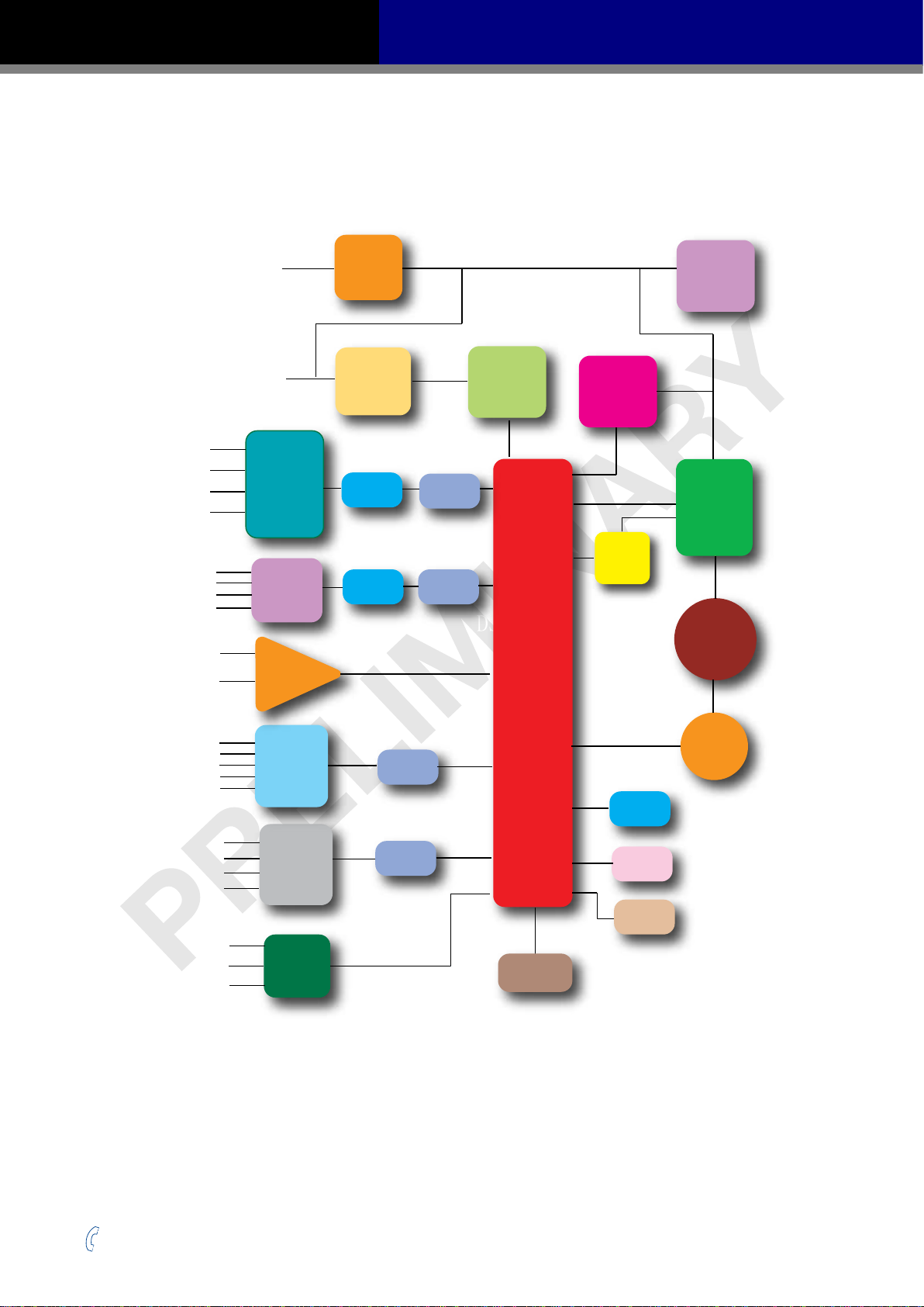
1.2 Block Diagram
SS EtherCAT Block Diagram
Power Supply
(24-70VDC)
Auxiliary Power
(12-48VDC)
X1+
X1-
X2+
X2-
X3+
X3-
X4+
X4-
ANALOG1
ANALOG2
High
Speed
Input
Optical
Isolation
Input
Optical
Isolation
Operational
Amplifter
EMC
Filter
DC Input
Power
Converter
Digital
Filter
Digital
Filter
Software
Filter
Software
Filter
DSP
Internal
Logic
Supply
DSP
Internal
Regen
Clamp
Voltage
Temp.
Det.
Mosfet
PWM
Power
Amplifier
Over
Current
Det.
Motor
X5
X6
X7
X8
XCOM
Y1+/Y2+/Y3+/Y4+/-
A+/-
B+/-
Z+/-
Single
Ended
Input
Isolation
Output
Optical
Isolation
Encoder
Output
Software
Filter
Software
Filter
Encoder
USB
EtherCAT
STO
LED
+86-400-820-9661
5
Rev. 1.0
2016/7/30

SS03/05/10-EC Hardware Manual
1.3 Safety Instructions
Only qualied personnel should transport, assemble, install, operate, or maintain this equipment.
Properly qualied personnel are persons who are familiar with the transport, assembly, installation,
operation, and maintenance of motors, and who meet the appropriate qualications for their jobs.
To minimize the risk of potential safety problems, all applicable local and national codes regulating
the installation and operation of equipment should be followed. These codes may vary from area
to area and it is the responsibility of the operating personnel to determine which codes should be
followed, and to verify that the equipment, installation, and operation are in compliance with the
latest revision of these codes.
Equipment damage or serious injury to personnel can result from the failure to follow all applicable
codes and standards. MOONS’ does not guarantee the products described in this publication
are suitable for a particular application, nor do they assume any responsibility for product design,
installation, or operation.
• Read all available documentation before assembly and operation. Incorrect handling of the
products referenced in this manual can result in injury and damage to persons and machinery.
All technical information concerning the installation requirements must be strictly adhered to.
• It is vital to ensure that all system components are connected to earth ground. Electrical safety
is impossible without a low-resistance earth connection.
• This product contains electrostatically sensitive components that can be damaged by incorrect
handling. Follow qualied anti-static procedures before touching the product.
• During operation keep all covers and cabinet doors shut to avoid any hazards that could
possibly cause severe damage to the product or personal health.
• During operation, the product may have components that are live or have hot surfaces.
• Never plug in or unplug the Integrated Motor while the system is live. The possibility of electric
arcing can cause damage.
Be alert to the potential for personal injury. Follow recommended precautions and safe operating
practices emphasized with alert symbols. Safety notices in this manual provide important
information. Read and be familiar with these instructions before attempting installation, operation, or
maintenance. The purpose of this section is to alert users to the possible safety hazards associated
with this equipment and the precautions necessary to reduce the risk of personal injury and damage
to equipment. Failure to observe these precautions could result in serious bodily injury, damage to
the equipment, or operational diculty.
Rev. 1.0
2016/7/30
6
+86-400-820-9661

SS03/05/10-EC Hardware Manual
2 Getting Started
The following items are needed:
• A 24-70 volt DC power supply, see Section 2.7 “Choosing a Power Supply” for help in choosing
the right one.
• An optional 12-48 volt DC power supply for Keep Alive function
• A compatible SS motor, see Section 5.3 “Recommended Motors and Specications”
• A small at blade screwdriver for tightening the connectors (included)
• A PC running Microsoft Windows XP, Windows 7, Windows 8/10 (32-bit or 64-bit) operating
system
• A mini USB cable for conguration (not included)
• Step-ServoQuickTuner software (available from MOONS’ website)
• A CAT5 cable for EtherCAT daisy chain connection (included)
• An STO connector for CN4 connection (included)
• Optional motor extension cable
• Optional encoder extension cable
• Optional I/O cable
2.1 Installing the Software
Step-ServoQuickTuner is the PC based software application used to congure and perform servo
tuning, drive testing, and evaluation on MOONS’ step-servo products. System servo control gains,
drive functionality, and I/O conguration are set with Step-ServoQuickTuner. It also contains an
oscilloscope function to help to set the servo control gains.
• Download the Step-Servo Quick Tuner from the MOONS’ website and install it.
• Launch the software by clicking Start -- Programs -- MOONS’
• Connect the drive to the PC with the mini USB cable. Select right COM port in the software. See
Section 2.4 “Choosing the Right COM Port”.
• Connect the drive to the power supply.
• Connect the motor to the drive.
+86-400-820-9661
7
Rev. 1.0
2016/7/30
SS03/05/10-EC Hardware Manual
2.2 Mounting the Drive
Use M4 screws to securely mount the SS-EC series drive to a smooth, at metal surface that will
help to conduct heat away from the chassis. If a heat conducting surface is not available, forced
airow from a fan may be required to prevent the drive from overheating.
• Never use the drive in a place where there is no air ow or the surrounding air is
more than 40°C.
• Never put the drive where it can get wet or where metal or other electrically
conductive particle particles can get on the circuity.
• Always provide air ow around the drive. When mounting multiple SS drives near
each other, maintain at least 1.5cm of space between drives.
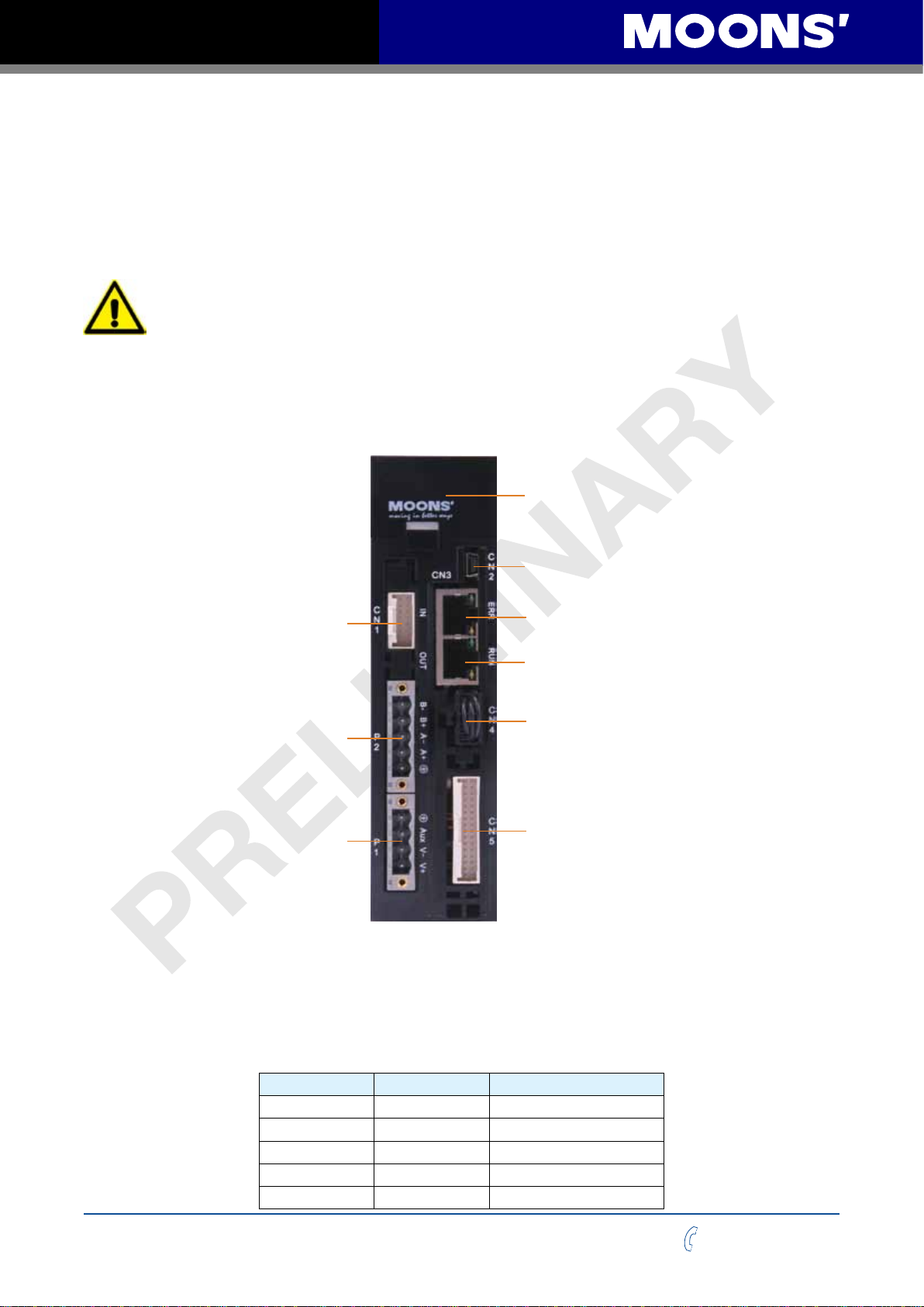
The connectors and other points of interest are illustrated below:
Control Panel
(LED display and keys)
Encoder Connector
Motor Connector
Power Connector
2.3 Connecting to the PC using mini USB
Mini USB
EtherCAT LINK IN
EtherCAT LINK OUT
STO
I/O Connector
Port CN2 is used to connect the drive with PC. Use Step-ServoQuickTuner software to congure
the drive and perform servo tuning and drive testing.
PIN Symbol Function
1 +5V +5V Power Supply
2 D- Data3 D+ Data+
4 - Reserved
5 GND Ground
Rev. 1.0
2016/7/30
8
+86-400-820-9661
SS03/05/10-EC Hardware Manual
P1
V
V
AUX
-
+
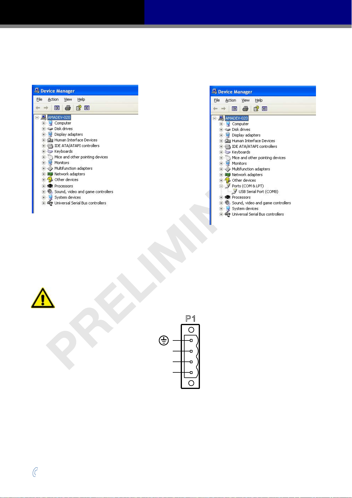
2.4 Choosing the Right COM Port
Open the “Device Manager” on the PC. There may or may not be a “Ports” selection. Connect the
mini USB cable to the PC. The connected COM port should then be displayed. Choose this new
COM(n) port in the Step-Servo Quick Tuner software.
2.5 Connecting the Main Power Supply
Connect power supply “+” terminal to the drive terminal labeled “V+”.
Connect power supply “-” terminal to the drive terminal labeled “V-”.
The SS-EC accepts DC voltage ranging from 24 to 70VDC
Warning: DO NOT reverse the wires
NOTE: DO NOT apply power until all connections to the drive have been made
Power Connector
Read Section 2.7 “Choosing a Power Supply” for more details.
+86-400-820-9661
9
Rev. 1.0
2016/7/30

SS03/05/10-EC Hardware Manual
2.6 Connecting the Auxiliary Power Supply
If the Keep Alive function is needed, an auxiliary power supply is required.
Connect the auxiliary power supply “+” terminal to the drive terminal labeled “AUX”.
Connect the auxiliary power supply “-” terminal to the drive terminal labeled “V-”.
The SS-EC auxiliary Power Supply input accepts DC voltage range from 12 to 48VDC.
Warning: DO NOT reverse the wires
NOTE: DO NOT apply power until all connections to the drive have been made
2.7 Choosing a Power Supply
The main considerations when choosing a power supply are the voltage and current requirements of
the application.
2.7.1 Supply Voltage
The SS-EC is designed to give optimum performance at 24-48 volts DC. Choosing the voltage
depends on the performance needed and the motor/drive heating that is acceptable and/or does not
cause a drive over-temperature. Higher voltages will give higher speed performance but will cause
the SS-EC to produce higher temperatures. Using power supplies with voltage outputs that are near
the drive’s maximum may signicantly reduce the operational duty-cycle.
The extended range of operation can be as low as 18VDC minimum to as high as 75VDC
maximum. When operating below 18VDC, the SS-EC may become unstable. The supply input
cannot go below 18VDC for reliable operation. If the input supply drops below 18VDC the under
voltage alarm will be triggered and the drive will stop working.
Absolute maximum power supply input is 75VDC at which point an over-voltage alarm and fault
will occur. When using a power supply that is regulated and is near the drive maximum voltage of
75VDC, a voltage clamp may be required to prevent over-voltage when regeneration occurs. When
using an unregulated power supply, make sure the no-load voltage of the supply does not exceed
the drive’s maximum input voltage of 75VDC.
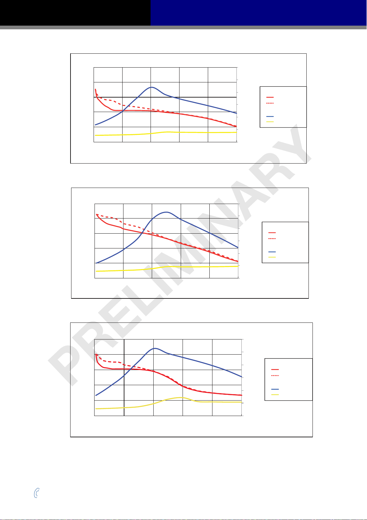
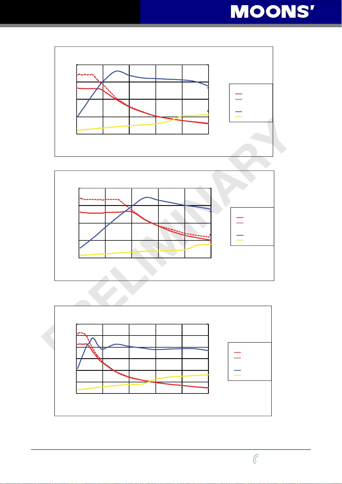
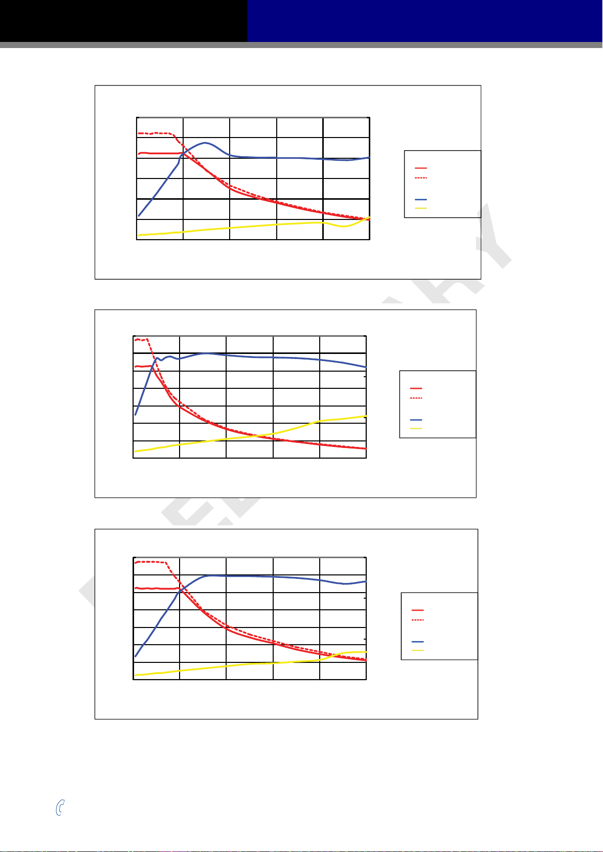
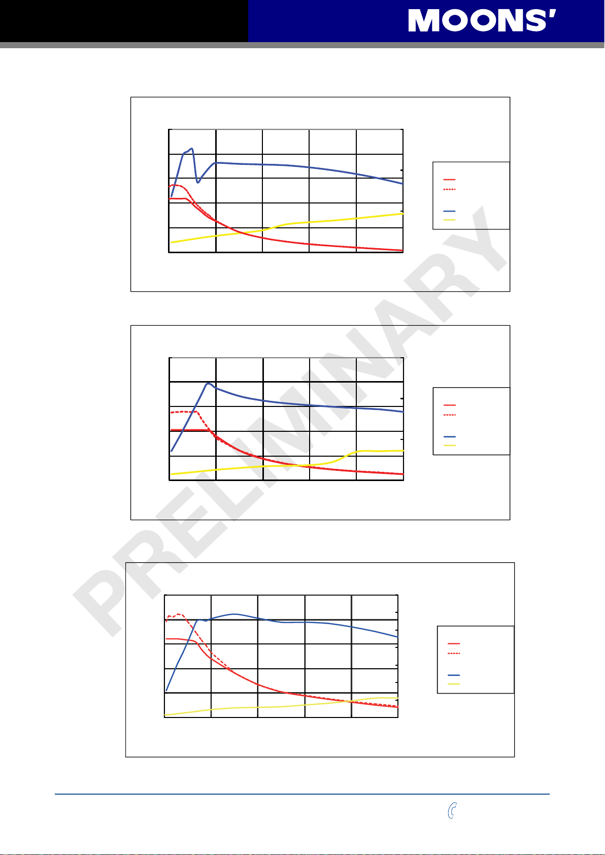
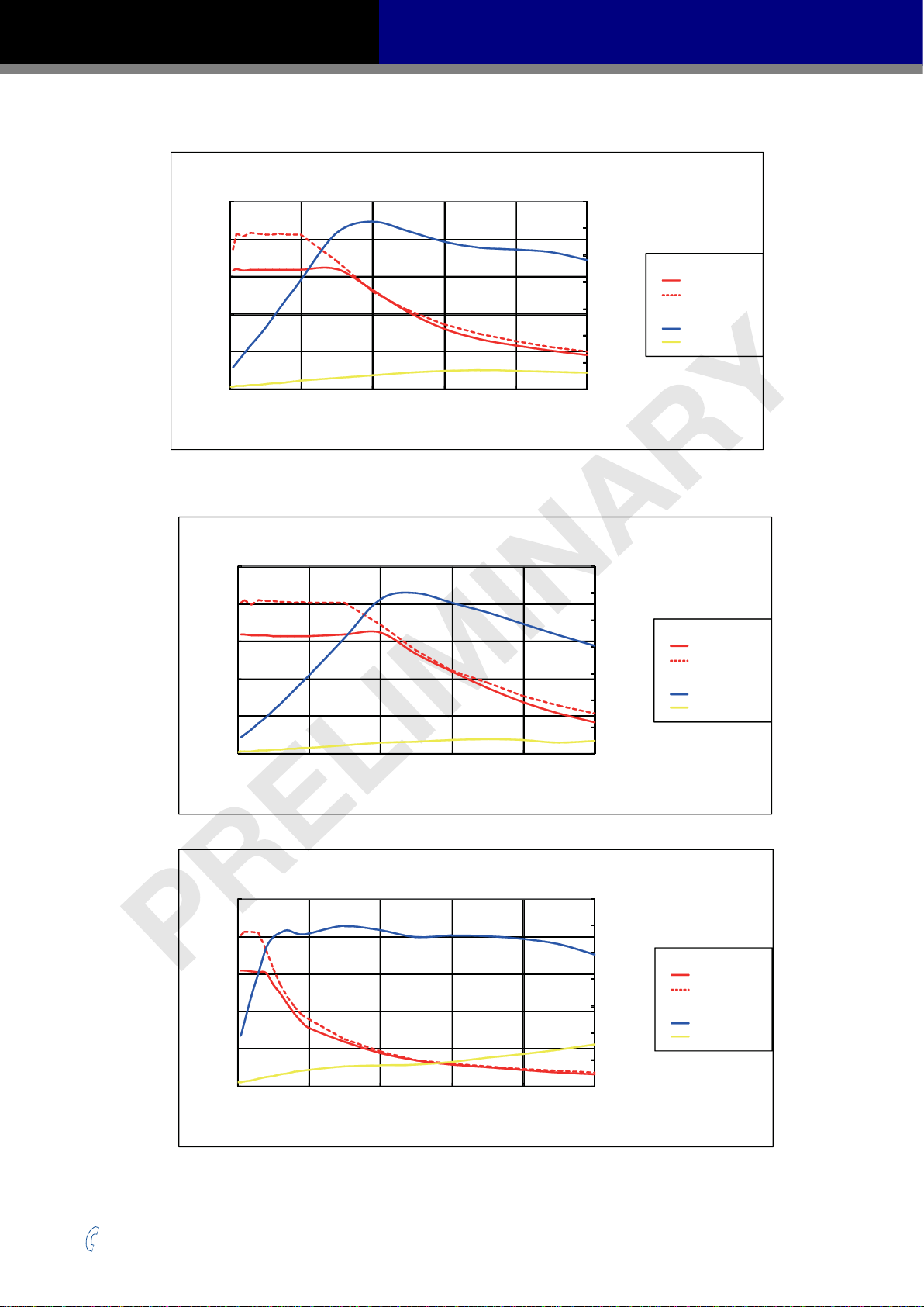
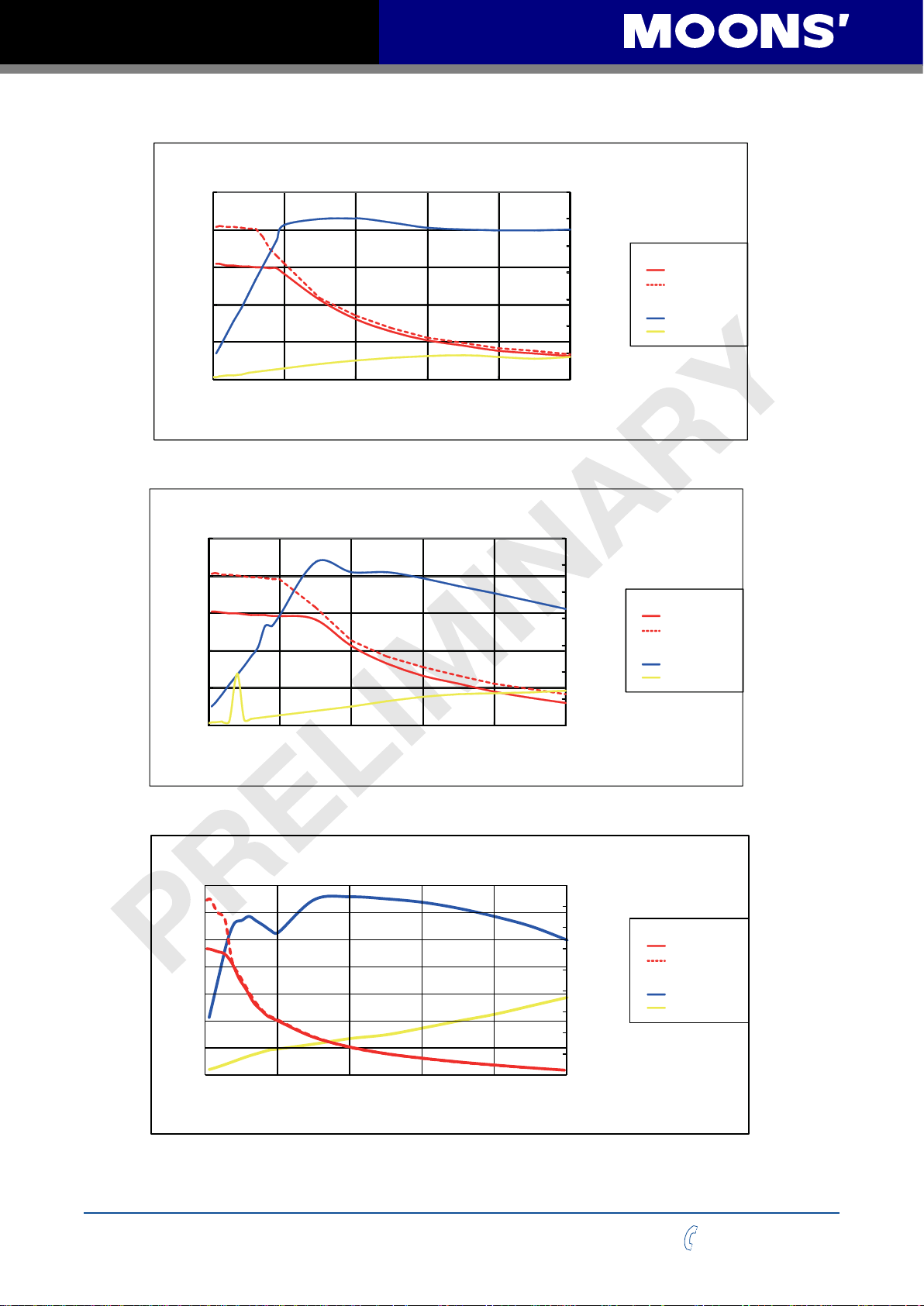
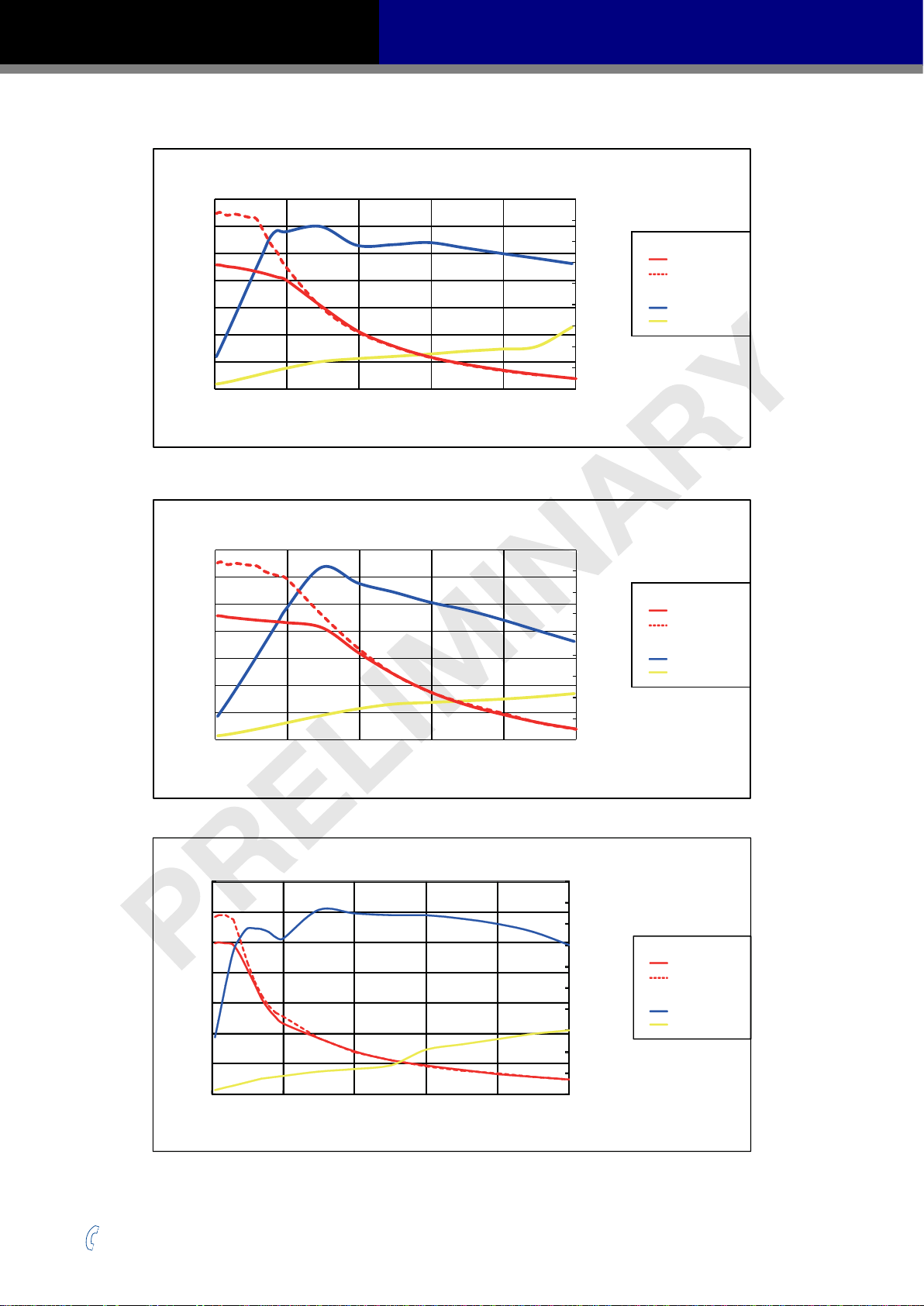
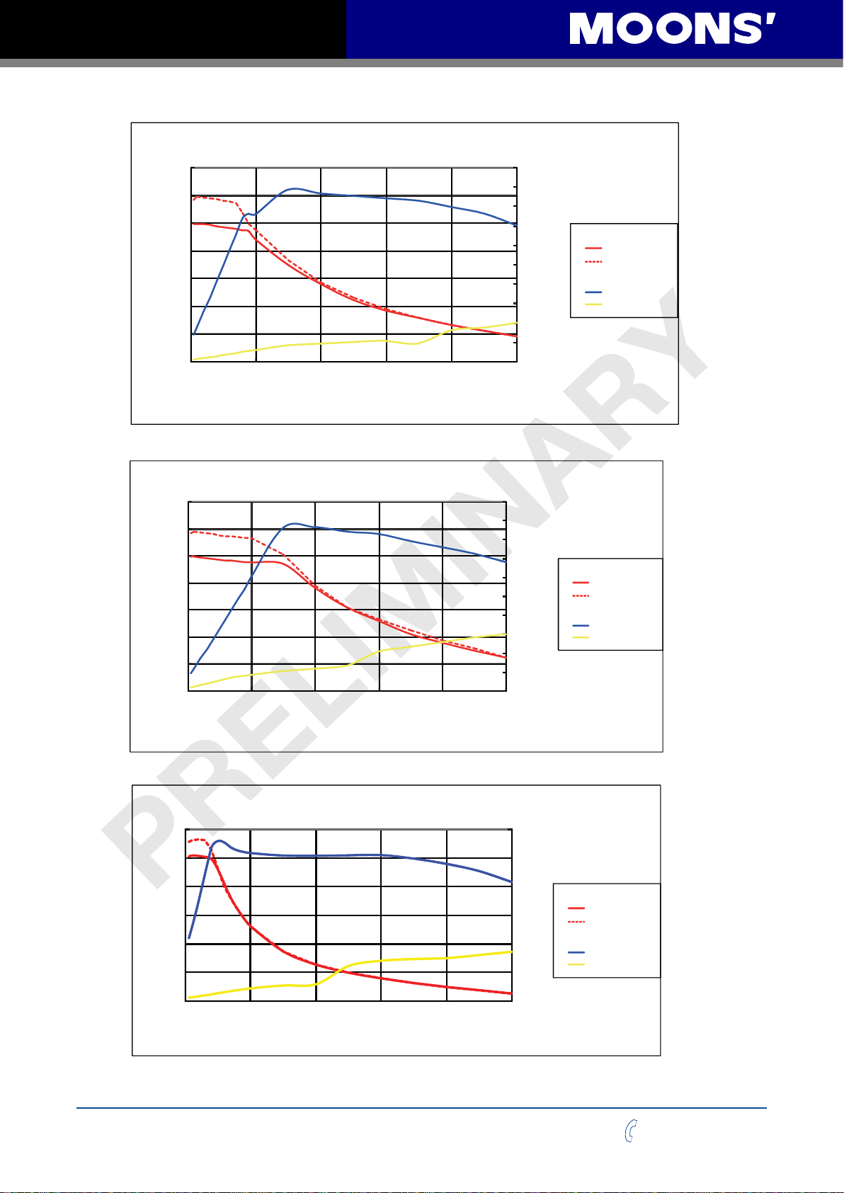
2.7.2 Supply Current
The maximum supply currents required by the SS-EC are shown in the charts below at dierent
power supply voltage inputs. The SS-EC power supply current is lower than the winding currents
because it uses switching ampliers to convert a high voltage and low current into lower voltage and
higher current. The more the power supply voltage exceeds the motor voltage, the less current will
be required from the power supply.
It is important to note that the current draw is signicantly dierent at higher speeds depending on
the torque load to the motor. Estimating how much current is necessary may require a good analysis
of the load the motor will encounter.
Rev. 1.0
2016/7/30
10
+86-400-820-9661
SS03/05/10-EC Hardware Manual
100
AM11SS1DMA 24V Power
80
60
40
Torque(mN.m)
20
0
0 10 20 30 40 50
Speed(RPS)
AM11SS2DMA 24V Power
100
80
60
40
Torque(mN.m)
20
1.2
1.0
0.8
0.6
0.4
0.2
0.0
1.2
1.0
0.8
0.6
0.4
0.2
Torque
Supply Current
Amps
Torque
Supply Current
Amps
Continuous
Boost
Full Load
No Load
Continuous
Boost
Full Load
No Load
0
0 10 20 30 40 50
Speed(RPS)
AM11SS3DMA 24V Power
150
120
90
60
Torque(mN.m)
30
0
0 10 20 30 40 50
Speed(RPS)
0.0
1.2
1.0
0.8
0.6
0.4
0.2
0.0
Torque
Supply Current
Amps
Continuous
Boost
Full Load
No Load
+86-400-820-9661
11
Rev. 1.0
2016/7/30
SS03/05/10-EC Hardware Manual
AM11SS3DMA 24V Power
0.0
0.2
0.4
0.6
0.8
1.0
1.2
0
30
60
90
120
150
0 10 20 30 40 50
Torque(mN.m)
Speed(RPS)
Amps
Continuous
Torque
Boost
Supply Current
Full Load
No Load
AM17SS1DG□-N 24V Power
0.4
0.3
0.2
Torque(N.m)
0.1
1.5
1
0.5
Torque
Supply Current
Amps
Continuous
Boost
Full Load
No Load
0
0 10 20 30 40 50
Speed(RPS)
AM17SS1DG□-N 48V Power
0.4
0.3
0.2
Torque(N.m)
0.1
0
0 10 20 30 40 50
Speed(RPS)
0
1.5
1
0.5
Torque
Supply Current
Amps
Continuous
Boost
Full Load
No Load
0
AM17SS2DG□-N 24V Power
0.6
0.5
0.4
0.3
0.2
Torque(N.m)
0.1
0
0 10 20 30 40 50
Speed(RPS)
Rev. 1.0
2016/7/30
12
1.5
1
0.5
0
Torque
Supply Current
Amps
Continuous
Boost
Full Load
No Load
+86-400-820-9661
SS03/05/10-EC Hardware Manual
0.0
0.2
0.4
0.6
0.8
1.0
1.2
Amps
Continuous
Torque
Boost
Supply Current
Full Load
No Load
AM17SS2DG□-N 48V Power
0.6
0.5
1.5
0.4
0.3
0.2
Torque(N.m)
0.1
0
0 10 20 30 40 50
Speed(RPS)
AM17SS3DG□-N 24V Power
0.7
0.6
0.5
0.4
0.3
0.2
Torque(N.m)
0.1
1
0.5
0
1.5
1
0.5
Torque
Supply Current
Amps
Torque
Supply Current
Amps
Continuous
Boost
Full Load
No Load
Continuous
Boost
Full Load
No Load
0
0 10 20 30 40 50
0.7
0.6
0.5
0.4
0.3
0.2
Torque(N.m)
0.1
0
0 10 20 30 40 50
+86-400-820-9661
Speed(RPS)
AM17SS3DG□-N 48V Power
Speed(RPS)
13
0
1.5
1
0.5
0
Torque
Supply Current
Amps
Continuous
Boost
Full Load
No Load
Rev. 1.0
2016/7/30
SS03/05/10-EC Hardware Manual
1.5
1.2
0.9
0.6
Torque(N.m)
0.3
AM17SS4DG□-N 24V Power
1.5
1
0.5
Torque
Supply Current
Amps
Continuous
Boost
Full Load
No Load
0
0 10 20 30 40 50
Speed(RPS)
AM17SS4DG□-N 48V Power
1.5
1.2
0.9
0.6
Torque(N.m)
0.3
0
0 10 20 30 40 50
Speed(RPS)
0
1.5
1
0.5
0
Torque
Supply Current
Amps
Continuous
Boost
Full Load
No Load
Rev. 1.0
2016/7/30
AM23SS2DG□-N 24V Power
1.5
1.2
0.9
0.6
Torque(N.m)
0.3
0
0 10 20 30 40 50
Speed(RPS)
14
3.5
3
2.5
2
1.5
1
0.5
0
Torque
Continuous
Boost
Supply Current
Amps
Full Load
No Load
+86-400-820-9661
SS03/05/10-EC Hardware Manual
AM23SS2DG□-N 48V Power
1.5
3.5
1.2
0.9
0.6
Torque(N.m)
0.3
0
0 10 20 30 40 50
Speed(RPS)
AM23SS2DG□-N 70V Power
1.5
1.2
0.9
0.6
Torque(N.m)
0.3
3
2.5
2
1.5
1
0.5
0
3.5
3
2.5
2
1.5
1
0.5
Torque
Supply Current
Amps
Torque
Supply Current
Amps
Continuous
Boost
Full Load
No Load
Continuous
Boost
Full Load
No Load
0
0 10 20 30 40 50
Speed(RPS)
AM23SS3DG□-N 24V Power
2.5
2
1.5
1
Torque(N.m)
0.5
0
0 10 20 30 40 50
Speed(RPS)
0
3.5
3
2.5
2
1.5
1
0.5
0
Torque
Supply Current
Amps
Continuous
Boost
Full Load
No Load
+86-400-820-9661
15
Rev. 1.0
2016/7/30
SS03/05/10-EC Hardware Manual
AM23SS3DG□-N 48V Power
2.5
3.5
2
1.5
1
Torque(N.m)
0.5
0
0 10 20 30 40 50
Speed(RPS)
AM23SS3DG□-N 70V Power
2.5
2
1.5
1
Torque(N.m)
0.5
3
2.5
2
1.5
1
0.5
0
3.5
3
2.5
2
1.5
1
0.5
Torque
Supply Current
Amps
Torque
Supply Current
Amps
Continuous
Boost
Full Load
No Load
Continuous
Boost
Full Load
No Load
0
0 10 20 30 40 50
Speed(RPS)
AM23SS4DGA-N 24V Power
3.5
3
2.5
2
1.5
1
Torque(N.m)
0.5
0
0 10 20 30 40 50
Speed(RPS)
0
4.5
4
3.5
3
2.5
2
1.5
1
0.5
0
Torque
Supply Current
Amps
Continuous
Boost
Full Load
No Load
Rev. 1.0
2016/7/30
16
+86-400-820-9661
SS03/05/10-EC Hardware Manual
AM23SS4DGA-N 48V Power
3.5
3
2.5
2
1.5
1
Torque(N.m)
0.5
0
0 10 20 30 40 50
Speed(RPS)
4.5
4
3.5
3
2.5
2
1.5
1
0.5
0
Torque
Supply Current
Amps
Continuous
Boost
Full Load
No Load
AM23SS4DGA-N 70V Power
3.5
3
2.5
2
1.5
1
Torque(N.m)
0.5
0
0 10 20 30 40 50
Speed(RPS)
AM24SS3DG□-N 24V Power
3.5
3
2.5
2
1.5
Torque(N.m)
1
0.5
0
0 10 20 30 40 50
Speed(RPS)
5
4.5
4
3.5
3
2.5
2
1.5
1
0.5
0
4.5
4
3.5
3
2.5
2
1.5
1
0.5
0
Torque
Supply Current
Amps
Torque
Supply Current
Amps
Continuous
Boost
Full Load
No Load
Continuous
Boost
Full Load
No Load
+86-400-820-9661
17
Rev. 1.0
2016/7/30
SS03/05/10-EC Hardware Manual
AM24SS3DG□-N 48V Power
3.5
3
2.5
2
1.5
Torque(N.m)
1
0.5
0
0 10 20 30 40 50
Speed(RPS)
5
4.5
4
3.5
3
2.5
2
1.5
1
0.5
0
Torque
Supply Current
Amps
Continuous
Boost
Full Load
No Load
AM24SS3DG□-N 70V Power
3.5
3
2.5
2
1.5
Torque(N.m)
1
0.5
0
0 10 20 30 40 50
Speed(RPS)
AM34SS1DGA-N 24V Power
3
2.5
2
1.5
1
Torque(N.m)
0.5
5
4.5
4
3.5
3
2.5
2
1.5
1
0.5
0
Torque
Continuous
Boost
Supply Current
Amps
Full Load
No Load
6
5
4
Torque
3
Amps
2
1
Continuous
Boost
Supply Current
Full Load
No Load
Rev. 1.0
2016/7/30
0
0 10 20 30 40 50
Speed(RPS)
18
0
+86-400-820-9661
 Loading...