

Moons' M2DV-1D82Q, M2DV-1D82S, M2DV-3D02Q, M2DV-4D52Q, M2DV-3D02R Quick Setup Manual Manual
...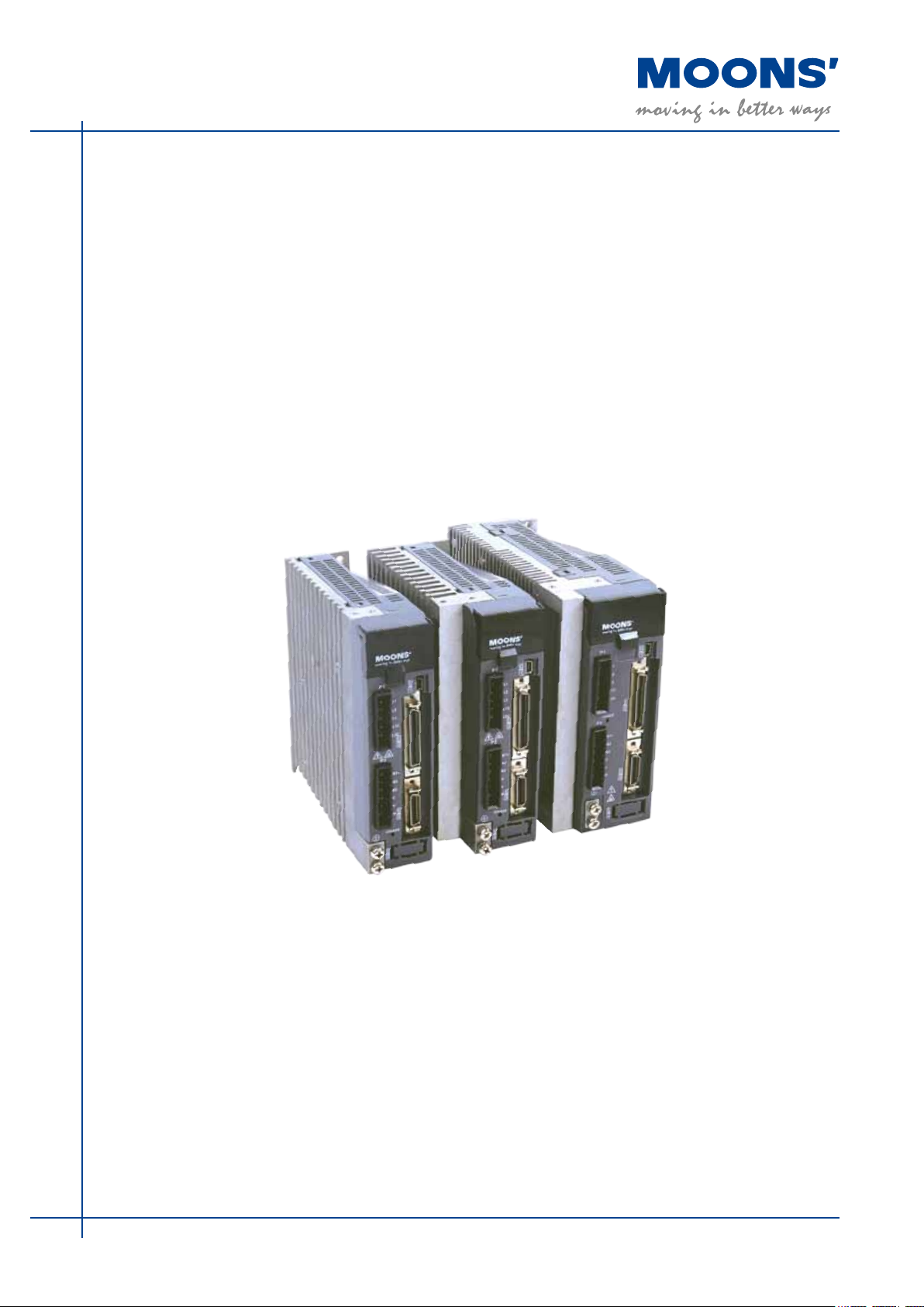
M2 Series AC Servo System
Quick Setup Guide Manual
SHANGHAI AMP & MOONS’AUTOMATION CO.,LTD.
Rev. 1.0
9/21/2015

M2 Quick Setup Guide Manaul
Safety
Only qualified persons may perform the installation procedures. The following explanations are for
things that must be observed in order to prevent harm to people and damage to property.
The M2 utilizes hazardous voltages. Be sure the drive is properly grounded.
Before you install the M2, review the safety instructions in this manual.
Failure to follow the safety instructions may result in personal injury or equipment damage.
Safety Symbols
Safety symbols indicate a potential for personal injury or equipment damage if the recommended
precautions and safe operating practices are not followed.
The following safety-alert symbols are used on the drive and in the documentat
ion:
Caution Warning. Dangerous voltage. Protective earth Caution,Hot surface
Safety Instructions
Installation
Wiring
Do not subject the product to water,corrosive or flammable gases,and combustibles.
Don’t use the motor in a place subject to excessive vibration or shock.
Never connect the motor directly to the AC power supply.
Don’t use cables soaked in water or oil.
Don’t extrude or pull-off the cable,nor damage the cables as electrical
shocks,damages may resul
Don’t block the heat dissipating holes. Please prevent
drive when mounting.
Don’t switch the power supply repeatedly.
Don’t touch the rotating shaft when the motor is running.
Don’t strike the motor when mounting as the motor shaft or encoder may be
damaged.
In order to prevent accidents, the initial trial run for servo motor should be conducted
under no load conditions (separate the motor from its couplings and belts).
Starti
ng the operation without matching the correct parameters may result in servo
drive or motor damage, or damage to the mechanical system.
Don’t touch either the drive heat sink or the motor and regenerative resister during
operation as they may become hot.
Don’t hold the motor cable during the transportation or mounting.
Don’t connect any power supplies to the U,V,W teminals.
Install the encoder cable in a separate conduit from the motor power cable to avoid
signal noise.
Use multi-stranded twisted-pair wires or multi-core shielded-pair wires for
signal,encoder cables.
As a charge may still remain in the drive with hazardous voltage even after power has
been removed, Don’t touch the terminals when the charge led is s
Please observe the specified voltage.
Make sure both the drive and the motor connect to a class 3 ground.
Please ensure grounding wires are securely connected when power up.
any metal filings drop into the
till light.
Standards Compliance
The M2 Series AC servo drive has been designed according to standards:
* Electromagnetic compatibility * Electrical Safety: Low voltage directive
Standard EN 61800-3 (2004) Standard IEC 61800-5-1 (2007)
Rev. 1.0
4/29/2016
2

M2 Quick Setup Guide Manaul
Contens
1 Product Description ..................................................................... 5
1.1 Unpacking Check ................................................................................5
1.2 Servo Drive Model Introduction .........................................................5
1.2.1 Drive Name Plate Description ................................................................5
1.2.2 Drive Model Description ..........................................................................5
1.3 Servo Motor Model Introduction .........................................................6
1.3.1 Motor Name Plate Description ................................................................6
1.3.2 Motor Model Description .........................................................................6
1.4 Servo Drive and Servo Motor Combinations ......................................6
2 Installation ................................................................................... 7
2.1 Storage Conditions .............................................................................7
2.2 Installation Conditions .........................................................................7
2.3 Drive Dimensions(Unit: mm) ............................................................... 7
2.4 Installation Space ...............................................................................8
2.5 Motor Installation ................................................................................8
3 Connections and Wiring .............................................................. 9
3.1 Connecting to Peripheral Devices ......................................................9
3.1.1 System Conguration .............................................................................. 9
3.1.2 Servo Drive Connectors and Terminals ................................................. 10
3.1.3 Connections and Wiring Notes .............................................................. 10
3.2 Wiring Methods ................................................................................. 11
3.2.1 Single-Phase Power Supply Connection(AC220V) ............................... 11
3.2.2 Three-Phase Power Supply Connection(AC220V) ............................... 11
3.2.3 Recommend Cable Specications ........................................................12
3.3 Wiring to the Connector,P2 ............................................................... 12
3.3.1 Motor Power Cable Conguration .........................................................12
3.3.2 Motor Power Cable Connector Specications ...................................... 13
3.3.3 Wiring Diagram of Motor extend Cable .................................................13
3.4 Electromagnetic Brake .....................................................................14
3.4.1 Wiring Diagram ...................................................................................... 14
3.4.2 Notice for the Brake Motor ....................................................................14
3.4.3 The timing charts of the electromagnetic brake ....................................14
3.5 Regenerative Resister .....................................................................15
3.6 Connect to Host Computer,CN1 .......................................................15
3.7 Input and Output Signal Interface Connector,CN2 ...........................15
3
Rev. 1.0
4/29/2016

M2 Quick Setup Guide Manaul
3.7.1 Input and Output Interface Diagram ......................................................16
3.7.2 Signals Description of Connector CN2 .................................................17
3.7.2.1 The Layout of CN1 Connector ............................................................17
3.7.2.2 Input Signals .......................................................................................17
3.7.2.3 Output Signals .....................................................................................19
3.7.3 Encoder Feedback Ouput .....................................................................19
3.7.3.1 A/B/Z Wiring Method ........................................................................... 19
3.7.3.2 Phase Z Open Collector Output .......................................................... 20
3.8 Encoder Connector CN3 ...................................................................20
3.8.1 Motor Encoder Feedback Cable Conguration .....................................20
3.8.2 The Layout of CN3 Connector ...............................................................20
3.8.3 Descriptions of Encoder Connector CN3 ..............................................21
3.8.4 Connect to Motor Encoder ....................................................................21
3.8.5 Specications of Encoder Connector ....................................................22
3.8.6 Wiring Diagram of Motor Encoder Extend Cable ..................................22
4 Control Block Diagram ............................................................... 23
4.1 Position Mode ...................................................................................23
4.2 Speed Mode .....................................................................................24
4.3 Torque Mode ..................................................................................... 25
5 Display and Operation ............................................................... 26
5.1 Description of Operation Panel ......................................................... 26
5.2 Key Lock ...........................................................................................26
5.3 Key Operation Flowchart ..................................................................27
6 Preoperational mode ................................................................. 28
6.1 Inspection Before Trail Tun ...............................................................28
6.2 Trail Run Procedure .......................................................................... 28
6.3 Motor Conguration Manually ........................................................... 29
6.4 Operations of JOG Mode .................................................................. 29
7 Troubleshooting ......................................................................... 30
7.1 Drive Alarm List .................................................................................30
7.2 Drive alarm reason and solutions ................................................31
8 Conguration by Personal Computer ........................................ 33
9 Appendix ................................................................................... 34
10 Contacting MOONS’ ................................................................ 35
Rev. 1.0
4/29/2016
4
M2 Quick Setup Guide Manaul
Model No.
Input/Output Voltage
Phase
Rated Current
Frequency
Rated Power
1 Product Description
1.1 Unpacking Check
Please refer to this section to confirm the model of servo drive and servo motor .
A complete and workable AC servo system should include the following parts:
1. Matched Servo drive and Servo motor
2. A power cable connect the drive to the servo motor(Option)
3. An feedback encoder cable connect the drive to the motor (Option )
4. A mini USB cable connect the port CN1 to PC for communication.(Opti
on)
5. 50-PIN connector (For I/O connections, Port CN2) Option
6. 26-PIN connector(For encoder feedback,Port CN3 ) Option
7. 6-PIN connector(IEEE1394,Option)
8. RJ-45 connectors (For RS-485 or CANopen communication,Port CN6 adn CN7)Option
9. 5-PIN connectors (For L1,L2,L3,L1C,L2C)
10. 6-PIN connector(For U,V,W,B1+,B2,B3)
1.2 Servo Drive Model Introduction
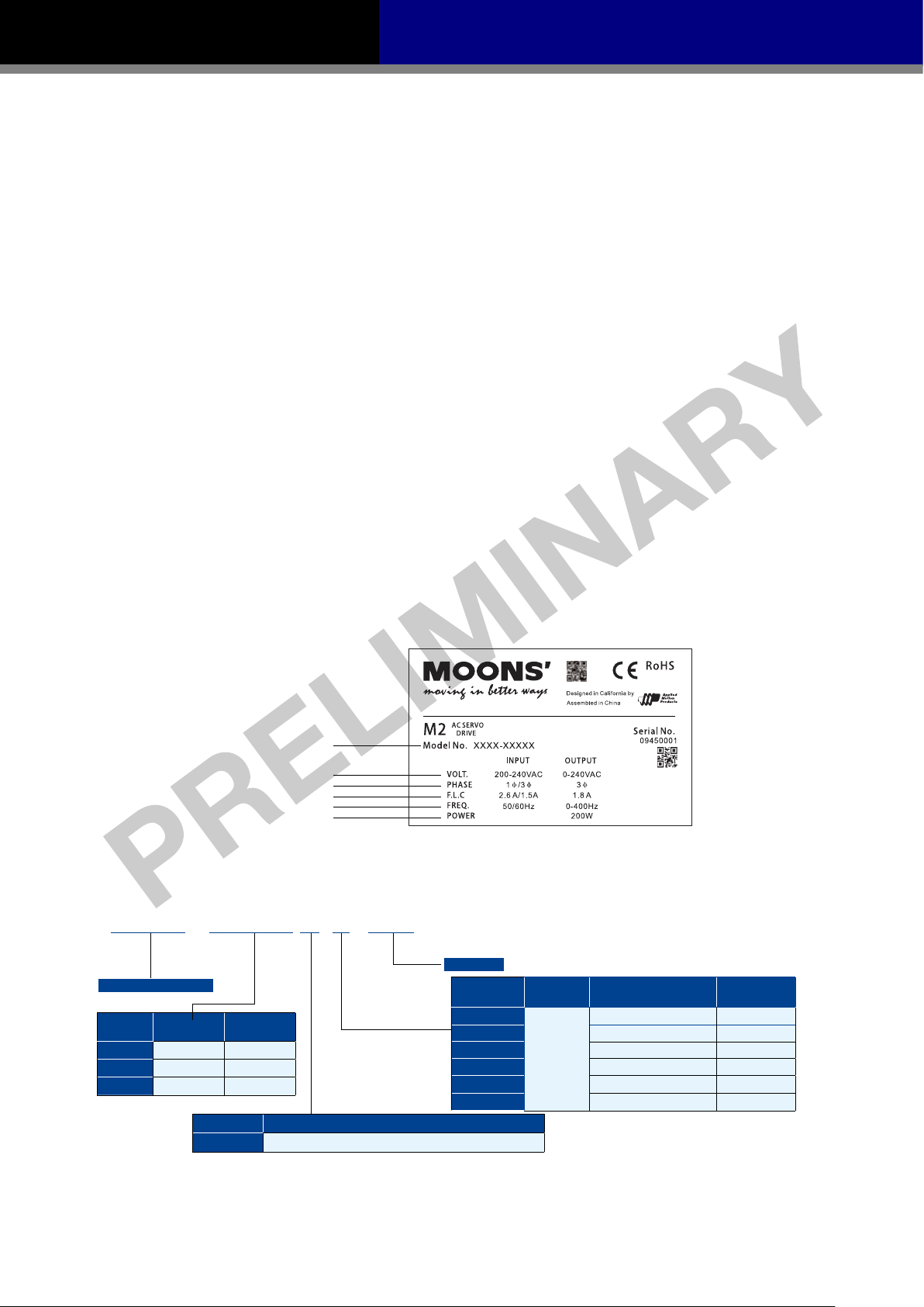
1.2.1 Drive Name Plate Description
1.2.2 Drive Model Description
M2DV -
M2 Series AC Servo Drive
Current
Code
Continuous
Current (RMS)
1D8 1.75A 5.25A
3D0 3.00A 9.00A
4D5 4.50A 13.50A
□ □ □ 2 □
Boost
Current (RMS)
Voltage Code Input Voltage
2
Single/Three-Phases200~240VAC±10%, 50/60Hz
***
If Applicable
Communication
Type
S
Q
R
C
IP
E
5
Configuration Description Communication
Mini USB
Basic Type
Q Type
Q Type(Modbus/RTU Type)
CANopen Type
EtherNet/IP
eSCL
Type
Type
- - -
RS-232
RS-485
CANBus
EtherNet
EtherNet
4/29/2016
Rev. 1.0
M2 Quick Setup Guide Manaul
S M 04 01 A E4-K CD-N N V
**
1.3 Servo Motor Model Introduction
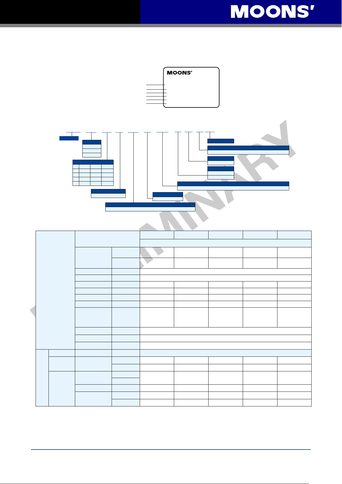
1.3.1 Motor Name Plate Description
Model NO.
Series NO.
Rated Torque
Input Current
Output Power
Rated Speed
1.3.2 Motor Model Description
Servo Motor
Frame Size
04-40mm
06-60mm
08-80mm
Motor Length
□40□60□
01 50W 200W
02 100W 400W
03 750W
04 1000W
80
Winding
A: 320 VDC(240 VAC)
E4: 2500 ppr Optical Encoder and Shared Commutation Tracks
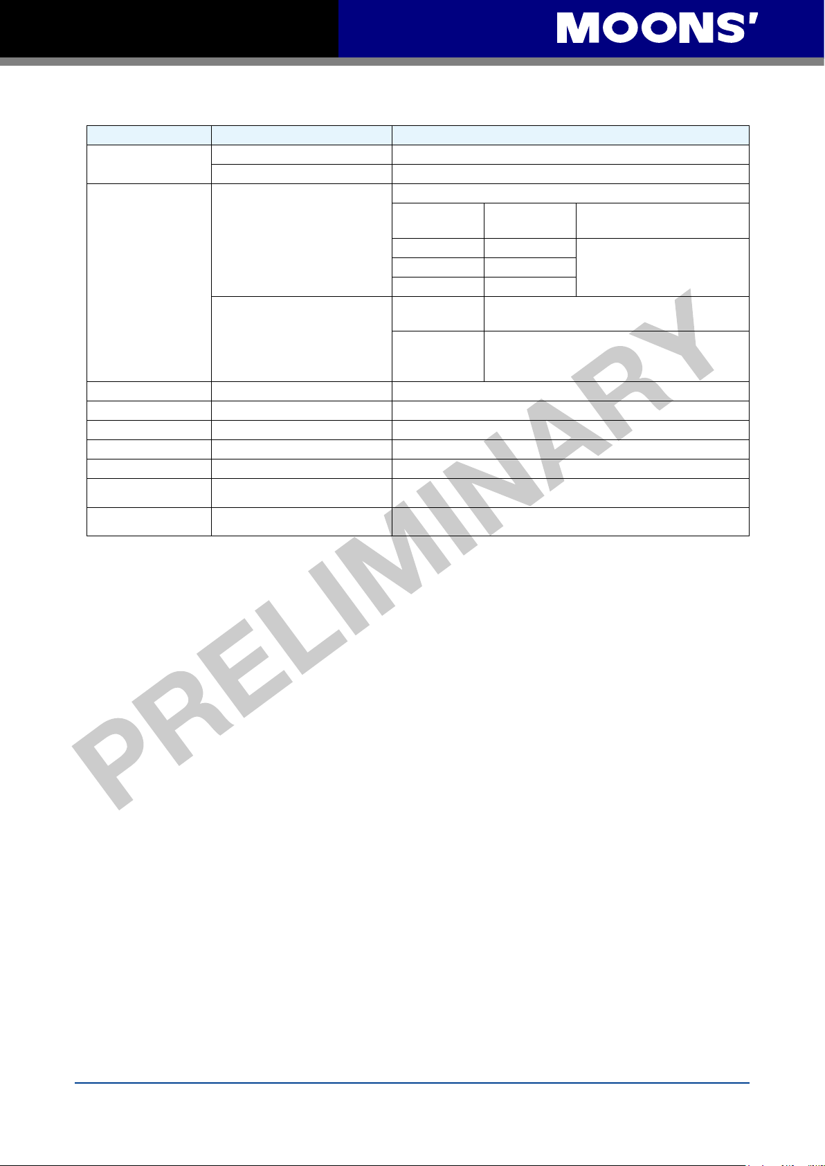
1.4 Servo Drive and Servo Motor Combinations
Specificatioon
2500ppr Increment
Encoder
(9PIN AMP connector)
Rated Speed
Maximum Speed
Rated Torque
AC Servo Motor
Pulse&Direction
Type
AC
Servo
Drive
Fieldbus Type
Maximum Torque
Rated Current
Maximum Current
Rotor Inertia
Insulation Class Class B
Protection Class IP65(except shaft through hole and cable end connetor)
il Seal With Oil seal
O
USB Mini
RS-485
CAN CANopen
Ethernet
Without Brake
With Brake
(RPM) 3000
(RPM) 6000
(N•m)
(N•m)
(A)
(A)
2
Kg•m
Basic Type
Q Type
SCL
Modbus RTU
Ethernet/IP
eSCL
AC SERVO MOTOR
Model NO.SM0602AE2-KCD-NNV15
Ser NO. 12110027
Rated Torque 1.27N
Input 3ØAC 220V 2.8A
Ouput 400W
Rated Rev. 3000r/min
CD: 300mm (12") Shielded Cables with AMP 4 Pin, 6-7 Amp Motor Connector.
Shaft
K: Standard Keyway
Ecoder
50W 100W 200W 400W 750W
SM0401AE4-KCD-
NNV09
SM0401AE4-KCD-
BNV09
0.19 0.32 0.64 1.27
0.48 0.93 1.9 3.8 6.9
0.7 1.2 1.5 2.75 4.5
1.75 3.6 4.5 8.3 13.5
0.0232×10-4
*0.0298×10
(*With Brake)
M2DV-1D82S M2DV-1D82S M2DV-1D82S M2DV-3D02S M2DV-4D52S
M2DV-1D82Q M2DV-1D82Q M2DV-1D82Q M2DV-3D02Q M2DV-4D52Q
M2DV-1D82R M2DV-1D82R M2DV-1D82R M2DV-3D02R M2DV-4D52R
M2DV-1D82C M2DV-1D82C M2DV-1D82C M2DV-3D02C M2DV-4D52C
M2DV-1D82IP M2DV-1D82IP M2DV-1D82IP M2DV-3D0
M2DV-1D82E M2DV-1D82E M2DV-1D82E M2DV-3D02E M2DV-4D52E
-4
SM0402AE4-KCD-
SM0402AE4-KCD-
0.0428×10
*0.0494×10
(*With Brake)
NNV09
BNV09
·m
Code
Connections
-4
-4
Shaft Seal
SM0602AE4-KCD-
NNV09
SM0602AE4-KCD-
BNV09
0.272×10
*0.326×10
(*With Brake)
V: Shaft seal shipped with motor, but not placed on shaft
Thermal Protector
N: No Protector
Brake Option
N: No Brake
B: 24VDC Brake
Motor Model Numbers
SM0601AE4-KCD-
NNV09
SM0601AE4-KCD-
BNV09
-4
-4
0.165×10
*0.22×10
(*With Brake)
Drive Model Numbers
SM0803AE4-KCD-
NNV09
SM0803AE4-KCD-
BNV09
2.4
-4
-4
2IP M2DV-4D52IP
0.89×10
*0.97×10
(*With Brake)
-4
-4
Rev. 1.0
4/29/2016
6
M2 Quick Setup Guide Manaul
2 Installation
2.1 Storage Conditions
Some Storage suggestions are followed:
• Correctly packaged and store in a clean and dry ,avoid direct sunlight
• Store within an ambient temperature range of -20℃ to +65
• Store within a relative humidity rang of 10% to 85% and non-condensing
• Don
’t store in a place subjected to corrosive gasses
2.2 Installation Conditions
The operation ambient conditions are followed:
• Temperature range of 0℃ to 50℃. If the ambient tempera
45℃, please install the drive in a well-ventilated location
The ambient temperature of servo dive for long-term reliability should be under 45℃.
• The servo drive and motor will generate heat. If they are installed in a control panel, please
ensure sufficient space around the units for heat dissipation.
• Operation within a relative humidity rang of 5%to
• The vibration lower than 5.88m/s
2
, 10-60Hz(Do not continuously use the drive for along time at
resonance point.)
• Don
’t mount the servo drive and motor in a location subjected to corrosive gasses or
flammable gases, and combustibles.
• Please mount the servo drive and motor to a indoor electric control cabinet without liquid and
direct sunlight
• Don
’t mount the servo drive and motor in a location subjected to airborne dust.
85% and non-condensing
℃
ture of servo drive is greater than
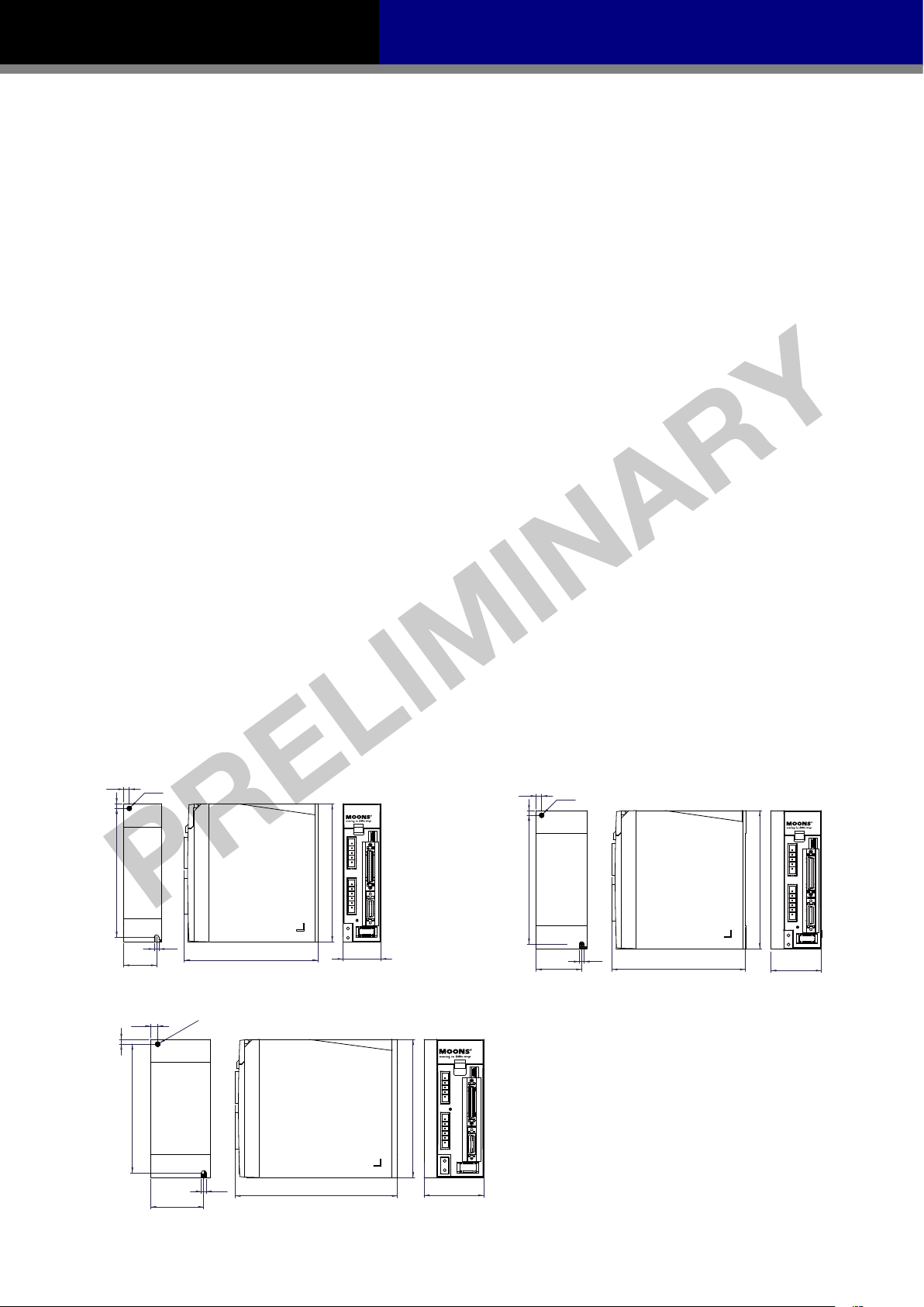
2.3 Drive Dimensions(Unit: mm)
50W、100W、200W Type
6
Ø5
5
140
5
35.5
750W Type
7.5
5
Ø5.2
140
145
150
41
150
400W Type
6
Ø5
5
140
49.5
150
5
145
55
57.5
5.2
176
65
7
Rev. 1.0
4/29/2016
M2 Quick Setup Guide Manaul
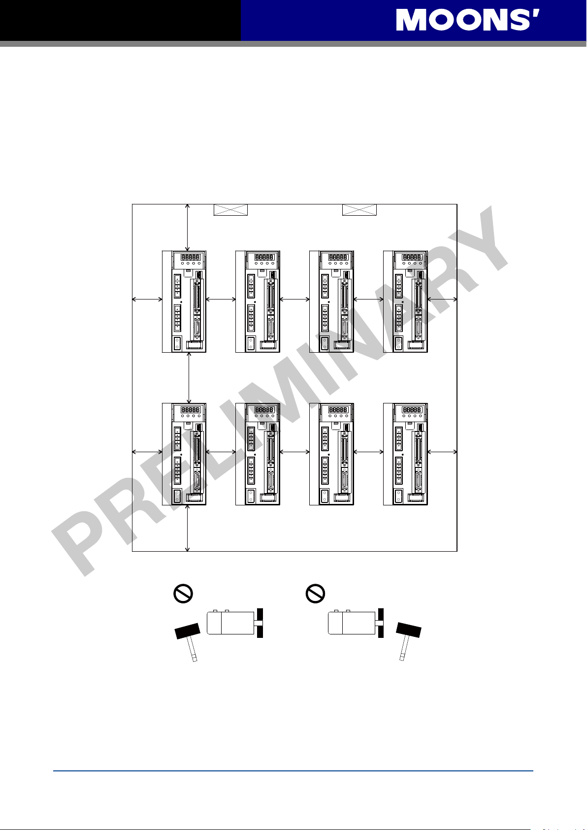
2.4 Installation Space
• Incorrect installation may result in a drive malfunction or premature failure of the drive and or
motor. Please follow the guidelines in this manual when installing the servo drive and motor.
• The M2 servo drive should be mounted perpendicular to the wall or in the control panel.
• In order to ensure the drive is well ventilated, ensure that the all ventilation holes are not
obstructed and suffic
the control panel.
• Please ensure grounding wires are securely connected
ient free space is given to the servo drive,and a cooling fan is mounted in
100mm
80mm
Fan Fan
10mm 10mm 10mm20mm
10mm 10mm 10mm20mm 20mm
20mm
100mm
2.5 Motor Installation
• Don't strike the motor when mounting as the motor shaft or encoder may be damaged.
• Don't use cables soaked in water or oil.
• Avoid a stress application to the cable outlet and connecting portion by bending
• Please use flexible cables when using cable carrier, make sure the minimum cable bending
radius is 200mm
• The shaft through hole and cable end connector is not IP65 design. Make sure to preve
liquid or oil into the motor from these parts.
Rev. 1.0
4/29/2016
8
nt any
M2 Quick Setup Guide Manaul
3 Connections and Wiring
3.1 Connecting to Peripheral Devices
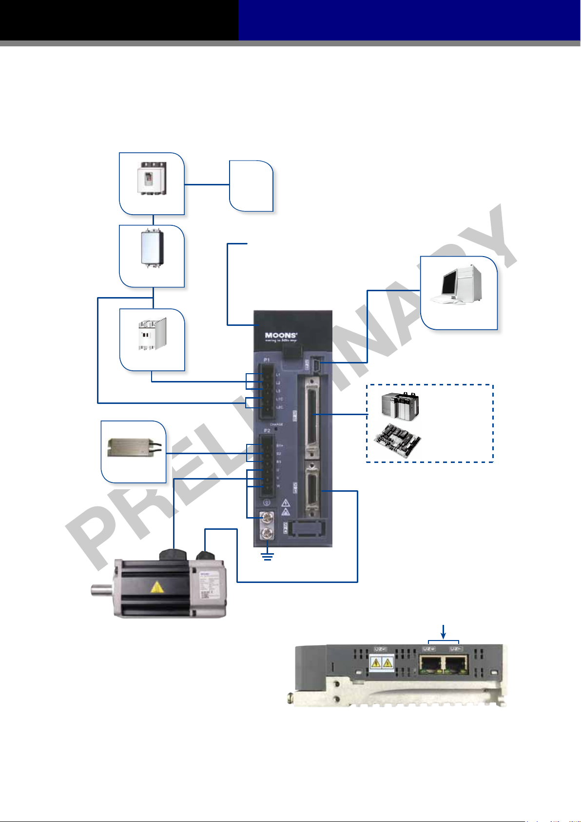
3.1.1 System Conguration
AC Power
Non Fuse Breaker
LED Display
The 5 digit,7 segment LED displays the
diver status and faults.
Operation Panel
Line Filter
(optional)
Function keys are used to perform status
display,monitor and diagnostic,function
and parameter setting.
Electromagnetic
Contactor
Regeneration
Absorbing Resistor
Main Power Input
Control Power Input
Motor Power Cable
Ground (PE)
Motor Feedback Cable
USB communication Port
(CN1)
PLC
Motion Control Card
I/O Interface
Used to connect PLC ,motion card
and other controllers.
Line Filter
AC Power Part No. Vendor
Single phase 240Vac 10ET1 Tyco
Three phase 240Vac DF300-10A-01 Dephir
CANBus, RS-485, Ethernet
Communication Port
9
Rev. 1.0
4/29/2016
M2 Quick Setup Guide Manaul
3.1.2 Servo Drive Connectors and Terminals
Terminal Identification Description Details
P1
P2
CN1 Communication Port User to connect personal computer
CN2 I/O Connector Used to connect external controllers.
CN3 Encoder Feedback Connector Used to connect encoder of servo motor.
CN4 Reserved
CN5 Reserved
CN6
CN7
L1、L2、L3 Used to connect three-phase AC main circuit power
L1C、L2C Used to connect single-phase AC for control circuit power
Used to connect servo motor
U、V、W
B1+、B2、B3
Regenerative resister terninals
RS-485/CANopen
*RS-2
32 Communication Port
RS-485/CANopen
Communication Port
Terminal
Symbol
U Red
V Yellow
W Blue
Internal
Resister
External
Resister
RJ45 connector, Daisy Chain, Used for RS-485/CANopen
*RS-232 Communication Port (-Q Type Only)
RJ45 connector, Daisy Chain, Used for RS-485/CANopen
Wire color Description
Ensure the circuit is closed between B2 and
and the circuit is open between B1+ and B3.
Ensure the circuit is open between B2 and B3,
and connect the external regenerative resister
between B1+ and B2.
Communication
Connecting to three-phase
motor main circuit cable
B3,
3.1.3 Connections and Wiring Notes
• Please ensure grounding wires are securely connected, wires with more than 2.0mm2 on width
is recommended.
• Grounding method must be single point grounding.
• Ensure L1/L2/L3 and
specification range.
• Ensure U/V/W are following the order of RED/YELLOW/BULE. Wrong connections will cause
motor stop rotation, or wrong rotatory directions.
• Isolation transformer or EMI filter is recommended on drive
safety and improve its anti-interference level.
• Please setup a emergence stop circ
• Please DO NOT touch drive or motors
powered off. There are electrical charge components in the circuitry. Therefore, even power is
off, there might still be hazardous voltages within the circuitry, before its total discharge.
• Install the encoder cables in a separate conduit from the
noise. Separate the conduits by 30cm (11.8inches) above.
• Use multi-stranded twisted-pair wires or multi-core shielded-pair wires for signal, encoder
feedback cables.
L1C/L2C are correctly wired, and voltage supply are within the
’s power supply to ensure drive’s
uitry to switch off the power supply when fault occurs.
’s connector terminals 5 minutes after drive and motor is
motor power cables to avoid signal
• The maximum length of signal input/output cable is 5m, and the maximum length of encoder
(PG) feedback cables is 15m
Rev. 1.0
4/29/2016
10

M2 Quick Setup Guide Manaul
3.2 Wiring Methods
220V AC servo drive supports single phase or three phase wiring method. Three phase wiring
method for 750W or above drives is recommended.
3.2.1 Single-Phase Power Supply Connection(AC220V)
L N E
MCCB
NF
P_on
P_off
E_stop
MC
Alarm
MC
Use external
regeneration resistor
B1+
B2
B3
regeneration resistor
Use Internal
MC
M2 Servo Drive
L1
L3
L1C
L2C
B1+
B2
B3
P1
P2
U
V
W
CN3
Alm_R
Red
Yellow
Blue
Yellow/Green
Ground
Encoder
Alm_R
3.2.2 Three-Phase Power Supply Connection(AC220V)
R
MCCB
NF
E
T
S
P_on
P_off
E_stop
MC
M
Encoder
24VDC
Alarm
MC
Use external
regeneration resistor
B1+
B2
B3
Use Internal
regeneration resistor
MC
M2 Servo Drive
L1
L2
L3
L1C
L2C
B1+
B2
B3
11
Alm_R
Red
U
Yellow
V
P2
W
CN3
Blue
Yellow/Green
Ground
Encoder
M
Encoder
Alm_R
24VDC
Rev. 1.0
4/29/2016

M2 Quick Setup Guide Manaul
Note:
Symbol Description
MCCB Circuit Breaker
NF Noise Filter
P_on Power On Switch
P_off Power Off Switch
E_stop Emergency Stop Switch
MC Magnetic Contactor
Alm_R Alarm Relay
Alarm Alarm Relay Contactor
3.2.3 Recommend Cable Specications
• For drive’s main circuit, please use wires withstands at least 600Vac.
• Please select wires with sufficient allowance for parameters such as operating current, and
ambient temperature.
• Recommended wire selections a
Matched Servo Drive and Motor
SM0401AE4-KCD-*NV
M2DV-1D82*
M2DV-3D02* SM0602AE4-KCD-*NV
M2DV-4D52* SM0803AE4-KCD-*NV
SM0402AE4-KCD-*NV
SM0601AE4-KCD-*NV
re as follows:
Wire Diameter mm
L1/L2/L3 L1C/L2C U/V/W B1+,B3
1.25
(AWG16)
1.25
(AWG16)
1.25
(AWG16)
2.0
(AWG14)
3.5
(AWG12)
1.25
(AWG16)
1.25
(AWG16)
1.25
(AWG16)
2.0
(AWG14)
3.5
(AWG12)
2
(AWG)
1.25
(AWG16)
1.25
(AWG16)
1.25
(AWG16)
2.0
(AWG14)
3.5
(AWG12)
2.0
(AWG14)
2.0
(AWG14)
2.0
(AWG14)
2.0
(AWG14)
3.5
(AWG12
)
3.3 Wiring to the Connector,P2
3.3.1 Motor Power Cable Conguration
P2 connector Interface of the Drive
extension cable connector
Motor power
NOTE: Please refer to section 3.3.2 Motor Power Cable Connector Specications for
details
Lead wire
of the motor connector
Rev. 1.0
4/29/2016
12

M2 Quick Setup Guide Manaul
3.3.2 Motor Power Cable Connector Specications
◆ PIN Assignment
A B
View A View B
PIN 1 2 3 4
Signal U V W PE
Colour Red Yellow Blue Yellow/Green
◆ Model of Motor Connector
Type Motor Side(Plug) Plug-in(Housing)
Housing AMP 172167-1 AMP 172159-1
Crimp
AMP 170360-1 AMP 170362-1
3.3.3 Wiring Diagram of Motor extend Cable
Drive Side(P2)
(JST) S06B-F32SK-GGXR AMP 172159-1
4 U Red 1
5 V Yellow 2
6 W Blue 3
Grounding Screw PE Yellow/Green 4
Signal Colour
NOTE: Ensure U/V/W are following the order of RED-YELLOW-BULE. Wrong connections
will cause motor stop rotation, or wrong rotatory directions.
Housing: 172159-1(AMP)
Terminal: 170362-1(AMP)
Motor Side(Housing)
13
Rev. 1.0
4/29/2016

M2 Quick Setup Guide Manaul
Servo Drive
3.4 Electromagnetic Brake
When motor drives the vertical axis, brake should be used to hold and prevent the work (moving
load) from falling by gravity while the power to servo is shut off.
NOTE: only use servo motor brake for hold the stalling status, i.e.. motor is in disable or
power off.
Never use this for “brake” purpose to stop the load in motion. Wrong use might cause
servo motor damage.
3.4.1 Wiring Diagram
24V
Relay
DC
Brake
Brake+
Brake-
Relay
R
24V
DC
3.4.2 Notice for the Brake Motor
◆When no power is applied to the electromagnetic brake, it is in locked position. Therefore, the
motor shaft will not be able to rotate.
◆The brake coil has no polarity.
◆During the brake/release action, there might be “Ka-Da” sounds occurring, this does not
effect the use of brake.
◆Specification of brakes are as follows:
Motor Power
Type 50W 100W 200W 400W 750W
Holding Torque(N•m) 0.35 2 4.5
Working Current(A) 0.25 0.38 0.61
Rated Voltage(V) 24V±10%
Release Time <25ms
Engage Time <25ms
Release Voltage(V) Release Voltage18.5VDC
3.4.3 The timing charts of the electromagnetic brake
In order to prevent damage to the brake, there are delay sequences during the brake operation.
Please be cautious with brake operation sequence.
Servo-on In Put
Motor Active
Brake Signal
Brake Action
Motion Command
Actual Motion
Brake/release delay time can be set via M servo suite software, or on the drive itself through P
function: P-68(BD) or P-69(BE) .
Rev. 1.0
4/29/2016
ON
OFF
ON
OFF
ON
OFF
ON
OFF
ON
OFF
ON
OFF
Brake Release Delay
P-68 Setting
14
Brake Engage Delay
P-69 Setting

M2 Quick Setup Guide Manaul
3.5 Regenerative Resister
In M2 series AC servo drives, there is a pre-installed 40W (M2DV-4D5 model: 60W )regeneration
resistor. In some applications, he pre-installed regeneration might not be enough to absorb all
fold back current. In these cases, a larger wattage regeneration resistor needs to be connected
externally, to prevent drive from over voltage warnings.
Ensure the circuit is closed between B2 and
B3,and the circuit is open between B1+ and
B3 when using internal resister.
Ensure the circuit is opened between
B2 and B3,and connect regenerative
resister between B1+ and B2 when
using external resister.
Regeneration
Resister
• For more detailed informations on regeneration resistor selection, please refer to M2 user
manual “regeneration resistor”.
3.6 Connect to Host Computer,CN1
Port CN1 is used to connect drive with PC. Use M servo suite software to set control mode,
change parameter values, use auto-tuning function and etc.
PIN Symbol Function
1 +5V +5V Power Supply
2 D- Data -
3 D+ Data +
4
5 GND Ground
—
Reserved
3.7 Input and Output Signal Interface Connector,CN2
The CN2 port on M2 series AC servo drives is used from input/output signals. Details are shown in
table below:
8 Configurable Optically isolate general High Speed Inputs, 5-24VDC, 20mA
2 Configurable Optically isolate general Inputs
4 Configurable Optically isolate general High Speed Outputs, max 30VDC,20mA
1 Alarm Output, max 30VDC,20mA.
1 motor brake control output, max 30VDC,100mA .
2 Analog Inputs, with 12bit resolution
2 Optically isolated high speed inputs 500Hz(Open collector)
2 high speed different
4 high speed encoder feedback output(3 Line Driver A/B/Z,and 1 open collector OZ)
ial inputs 2MHz
I/O
Signals
Inputs
Digital Signal
Outputs
Analog Signal Inputs
Inputs
Pulse Signal
Outputs
15
Rev. 1.0
4/29/2016

M2 Quick Setup Guide Manaul
3.7.1 Input and Output Interface Diagram
X1+
X1-
X2+
X2-
X3+
X3-
X4+
X4-
X5+
X5-
X6+
X6-
X7+
X7-
X8+
X8-
COM
X9
44
45
46
47
3
4
5
6
29
31
35
34
8
2
9
1
39
38
12
32
7
1.5K
26
1.5K
1.5K
Position
Command
PULSH1
High Speed
PULSH2
Pulse Input
SIGNH1
SIGNH2
STEP/CW
DIR/CCW
Enable
Alarm Reset
Limit Sensor
Limit Sensor
Gain Select
Control mode Switch
Dividing Switch
Analog Input
16
+
-
+
-
ANA1
Speed Command
15
DGND
18
ANA2
Torque Command
17
DGND
37
Y1+
Alarm Output
36
Y1-
11
Y2+
Motor Brake
Y2-
Y5+
Control Output
10
40
Servo Ready Output
41
Y5-
14
Y6+
In Position Output
13
Y6-
42
Y3
Torque Reached Output
43
Y4
Velocity Reached Output
33
OUT-
21
AOUT+
Encoder
Feedback
22
48
49
23
24
19
AOUT-
BOUT+
BOUT-
ZOUT+
ZOUT-
CZ
Output
Rev. 1.0
4/29/2016
SPD0
SPD1
SPD2
X10
X11
X12
27
1.5K
1.5K
28
1.5K
1.5K
30
1.5K
DGND
15
20
+10V User
User_GND
25
FG
50
16

M2 Quick Setup Guide Manaul
3.7.2 Signals Description of Connector CN2
3.7.2.1 The Layout of CN1 Connector
A
View AView B
B
3.7.2.2 Input Signals
M2 series AC servo drive have 12 programmable digital inputs as well as 2 analog inputs.
Each of the input can be specified with different function via parameter settings. The functions are
as follows:
◆Specified function signals: i.e. Pulse/DIR signal, motor enable/disable signals.
◆General purpose signal: In velocity mode, torque mode, Q program mode, or SCL mode,
17
Rev. 1.0
4/29/2016

M2 Quick Setup Guide Manaul
general purpose signal has no specified functions.
Signal Symbol Pin NO. Details
X1+ 3
X1
X1- 4
This input has three functions:
Accept STEP pulse input such as pulse signals, CW pulse, A pulse in
●
position mode.
Run/Stop input in torque or velocity mode.
●
General Input.
●
X2+ 5
X2
X2- 6
X3
X3+ 29
X3- 31
X4+ 35
X4
X4- 34
X5
X6
X7
X8
X5+ 8
X5- 2
X6+ 9
X6- 1
X7+ 39
X7- 38
X8+ 12
X8- 32
X9 X9 26
X10 X10 27
X11 X11 28
X12 X12 30
COM COM 7
PULSH1 44
PULSH2 45
High-speed pulse
SIGNH1 46
inputs
SIGNH2 47
Analog input
ANA1 16
signal 1
DGND 15
Analog input
ANA2 18
signal 2
DGND 17
This input has three functions:
Accept STEP pulse input such as Direction signals,CCW pulse,
●
B pulse in position mode.
Direction input in torque or velocity mode.
●
General Input.
●
Enable/Disable input.
●
General Input.
●
Alarm Reset Input,used to reset drive alarm.
●
General Input.
●
Limit Sensor Input
●
General Input
●
Limit Sensor Input
●
General Input
●
Gain Select Input in all control mode.
●
General Input.
●
Switch Control mode between Main mode and second mode.
●
General Input.
●
Dividing Sw
●
General Input.
●
Pulse Inhibited Input. Ignore the pulse input when this input is activated
●
in position mode.
Speed Selecting Input 1 in change Speed mode.
●
General Input.
●
Speed Selecting Input 2 in change Speed mode.
●
General Input.
●
Speed Selecting Input 3 in change Speed mode.
●
General Input.
●
X9-X12 COM point.
High-speed pulse inputs(+5VDC line drive input).The max. input frequency is
2MHz.Three different pulse command can be selected:
Pulse & Direction
●
CW Pulse and CCW Pulse
●
A Quadrature B pulse
●
(NOTE:DO NOT use it with X1/X2 both. )
AS velocity command in analog velocity mode. The offset ,dead band,
●
function of analog input 1 can be set by M Servo Suit or parameters
P-51, P-55 and P-60.
Sets or requests the analog Input gain that relates to motor position
●
when the drive is in analog position command mode.
Sets or requests the gain value used in analog velocity mode.
●
General Analog Input in Q mode.
●
Digital Ground for Analog input.
AS torque com
●
analog input 2 can be set by M Servo Suit or parameters P-53,P-57 and P-61.
General Analog Input in Q mode
●
Digital Ground for Analog input.
itch,change the pulses per revolution for electronic Gearing.
mand in analog torque mode. The offset ,dead band, function of
Rev. 1.0
4/29/2016
18

M2 Quick Setup Guide Manaul
3.7.2.3 Output Signals
M2 series AC servo drive has 6 programmable digital outputs available, each of the output can be
specified with different function via parameter settings.
Signal Symbol Pin NO. Details
This output has two functions:
Alarm Output
●
General Output
●
This output has two functions:
Motor brake control output
●
General Output
●
Torque Reached Output
●
General Output
●
Moving signal output, output signal when dynamic position error less
●
than set value in position mode.
Velocity reach output. Output signal when actual speed is same as the
●
target speed and the speed ripple less than ripple range.
General Output.
●
Servo ready output. Output servo ready signal when the drive is ready
●
to be controlled and without alarm.
General Output.
●
In position signal output, output signal when in position, and the
●
position error less than set value in position mode.
Tach out output. Tach output, produces pulses relative to the motor
●
position with configurable resolution.
General Output.
●
The encoder feedback phase A line drive output.
The encoder feedback phase B line drive output.
The encoder feedback phase Z line drive output.
The encoder feedback phase Z output.(Open collector)
+10Vdc user ,max 100mA
+10Vdc user Ground
Y1
Y2
Y3
Y4
Y5
Y6
Encoder pulse
feedback Output
+10V
Output
Y1+ 37
Y1- 36
Y2+ 11
Y2- 10
Y3+ 42
Y3- 33
Y4+ 43
Y4- 33
Y5+ 40
Y5- 41
Y6+ 14
Y6- 13
AOUT+ 21
AOUT- 22
BOUT+ 48
BOUT- 49
ZOUT+ 23
ZOUT- 24
ZOUT 19
+10V Us
er 20
USER_GND 25
3.7.3 Encoder Feedback Ouput
M2 series AC servo drive can output encoder A/B/Z phase as differential output signals through
line driver. The output signal is 5V, A/B signals are 10000 pulse/rev, Z signal is 1pluse/rev.
The host must use line receiver to receive the signals. Please use twist pair wires for signal
transfers.
3.7.3.1 A/B/Z Wiring Method
Servo Drive
21
AOUT+
22
AOUT-
48
BOUT+
49
BOUT-
23
ZOUT+
24
ZOUT-
DGND
25
50
FG FG
NOTE:Please make sure the host controller and the servo drive have a same ground.
Host Controller
A+
A-
B+
B-
Z+
Z-
DGND
19
Rev. 1.0
4/29/2016

M2 Quick Setup Guide Manaul
3.7.3.2 Phase Z Open Collector Output
In M2 series AC servo drive, encoder signal Z uses open collector output circuitry. Due to the
narrow bandwidth of encoder signal Z, please use high speed optocoupler circuitry for the host
receiver.
Servo Drive
CZ
19
DGND
15
3.8 Encoder Connector CN3
3.8.1 Motor Encoder Feedback Cable Conguration
驱动器CN3端
P2
B1+
B2
B3
U
V
C
N
W
3
编码器延长线连接头
24VDC
0VDC
编码器引出线编码器连接头
NOTE: Please refer to section 3.8.4 Encoder Connector Specications for details.
3.8.2 The Layout of CN3 Connector
Rev. 1.0
4/29/2016
1
2
12
13
15
14
26
25
View B
14
26
View A
1
13
A
20
B

M2 Quick Setup Guide Manaul
3.8.3 Descriptions of Encoder Connector CN3
Pin NO. Symbol Description
1 A+ Encoder A+
2 B+ Encoder B+
3 Z+ Encoder Z+
4 U+ Hall U+
5 W+ Hall W+
6 U- Hall U-
7 W- Hall W-
11 Encoder +5V Encoder power supply +5V
13 Encoder +5V Encoder power supply +5V
14 A- Encoder A-
15 B- Encoder B-
16 Z- Encoder Z-
17 V+ Hall V+
19 V- Hall V-
24 GND Encoder power supply ground
26 Shield Shield
3.8.4 Connect to Motor Encoder
A. Connect to 2500ppr Increment Encoder (9PIN AMP connector)
Servo Drive CN3
CN3
1
14
2
15
3
16
11
24
26
Motor Encoder
A+
1
A-
4
B+
2
B-
5
Z+
3
Z-
6
+5V
7
GND
8
Shield
9
A+
A-
B+
B-
Z+
Z-
+5V
GND
Shield
21
Rev. 1.0
4/29/2016

M2 Quick Setup Guide Manaul
A
3.8.5 Specications of Encoder Connector
A. 9PIN AMP Connector
◆PIN Assignment
1 3
7
9
View A
PIN#
1
2
3
4
5
6
7
8
9
Signal Colour
U+/A+ Blue
V+/B+ Green
W+/Z+ Yellow
U-/A- Yellow/Black
V-/B- Green/Black
W-/Z- Yellow/Black
+5V Red
GND Black
Shield Shield
NOTE: HALL signal U/V/W will only appear for 1.5 seconds when encoder power is applied,
and it will switch to A/B/Z signals after.
◆Specification of 9PIN AMP Connector
Type Plug of the Motor Housing for the motor
Housing AMP 172169-1 AMP 172161-1
Crimp AMP 770835-1 AMP 770834-1
3.8.6 Wiring Diagram of Motor Encoder Extend Cable
A. Diagram of 9PIN Encoder Cable
Rev. 1.0
4/29/2016
Connect to drive
Connect to Motor
Drive Side
3M 26PIN PIN脚 AMP 172161-1
Signal Colour
A
1
3
7
9
View A
Housing for the motor
1 A+/U+ Blue 1
2 B+/V+ Green 2
3 Z+/W+ Yellow 3
14 A-/U- Yellow/Black 4
15 B-/V- Green/Black 5
16 Z-/W- Yellow/Black 6
11 +5V Red 7
24 GND Black 8
26 Shield Shield 9
22

M2 Quick Setup Guide Manaul
4 Control Block Diagram
4.1 Position Mode
Differential Pulse Signal
Controller
VDC Spec.
DGND
Open Collector Output
VDC
5-24VDC
High Speed Differential Input
44
PULSH1
45
PULSH2
46
SIGNH1
47
SIGNH2
DGND
25
FG
Control mode Switch
VDC
Pulse Inhibited Input.
High Speed Pulse Input
PULSH1
PULSH2
SIGNH1
SIGNH2
X1+
X1-
X2+
X2-
X3+
X3-
Enable Signal Input
X4+
X4-
Alarm Reset
X5+
X5-
Limit Sensor
X6+
X6-
Limit Sensor
X7+
X7-
Gain Select
X8+
X8-
COM
X9
Dividing Switch
X10
X11
X12
44
45
46
47
3
4
5
6
29
31
35
34
8
2
9
1
39
38
12
32
7
1.5K
26
1.5K
1.5K
27
1.5K
1.5K
28
1.5K
1.5K
30
1.5K
Encoder
Feedback
Output
Analog Input
16
+
ANA1
15
18
17
37
36
11
10
40
41
14
13
42
43
33
21
22
48
49
23
24
15
19
15
50
DGND
ANA2
DGND
Y1+
Y1-
Y2+
Y2-
Y5+
Y5-
Y6+
Y6-
Y3
Y4
OUT-
AOUT+
AOUT-
BOUT+
BOUT-
ZOUT+
ZOUT-
DGND
CZ
DGND
FG
Speed Command
Torque Command
Alarm Output
Brake Control Output
Servo Ready
In Position
Torque Reached Output
Velocity Reached Output
A+
A-
B+
B-
Z+
Z-
DGND
5-24VDC
Drive
Encoder Phase A Output
Encoder Phase B Output
Encoder Phase Z Output
Phase Z (Open Collector Output)
5-24VDC
-
+
-
Note:VDC Spec. 5~24VDC
23
Rev. 1.0
4/29/2016

M2 Quick Setup Guide Manaul
4.2 Speed Mode
44
PULSH1
45
High Speed Pulse Input
Enable Signal Input
Alarm Reset
Limit Sensor
Limit Sensor
Gain Select
Control mode Switch
VDC
Pulse Inhibited Input.
PULSH2
SIGNH1
SIGNH2
X1+
RUN/STOP
Rotation Direction
X1-
X2+
X2-
X3+
X3-
X4+
X4-
X5+
X5-
X6+
X6-
X7+
X7-
X8+
X8-
COM
X9
X10
X11
46
47
3
4
5
6
29
31
35
34
8
2
9
1
39
38
12
32
7
1.5K
26
1.5K
1.5K
27
1.5K
1.5K
28
1.5K
1.5K
Encoder
Feedback
Output
Analog Input
16
+
-
+
-
ANA1
15
DGND
18
ANA2
17
DGND
37
Y1+
36
Y1-
11
Y2+
±10VDC
±10VDC
Alarm Output
Speed Command
Torque Command
Brake Control Output
10
Y2-
40
41
14
13
42
43
33
21
Y5+
Y5-
Y6+
Y6-
Y3
Y4
OUT-
AOUT+
Servo Ready
5-24VDC
In Position
Torque Reached Output
Velocity Reached Output
Drive
A+
Encoder Phase A Output
22
48
49
23
24
15
19
15
AOUT-
BOUT+
BOUT-
ZOUT+
ZOUT-
DGND
CZ
DGND
A-
B+
B-
Z+
Z-
DGND
Encoder Phase B Output
Encoder Phase Z Output
Phase Z (Open Collector Output)
5-24VDC
30
X12
Note:VDC Spec. 5~24VDC
Rev. 1.0
4/29/2016
1.5K
FG
50
24

M2 Quick Setup Guide Manaul
4.3 Torque Mode
44
PULSH1
45
RUN/STOP
PULSH2
SIGNH1
SIGNH2
X1+
X1-
X2+
X2-
X3+
X3-
X4+
X4-
X5+
X5-
X6+
X6-
X7+
X7-
X8+
X8-
COM
X9
X10
X11
46
47
3
4
5
6
29
31
35
34
8
2
9
1
39
38
12
32
7
1.5K
26
1.5K
1.5K
27
1.5K
1.5K
28
1.5K
1.5K
High Speed Pulse Input
Rotation Direction
Enable Signal Input
Alarm Reset
Limit Sensor
Limit Sensor
Gain Select
Control mode Switch
VDC
Encoder
Feedback
Output
Analog Input
16
+
-
+
-
ANA1
15
DGND
18
ANA2
17
DGND
37
Y1+
36
Y1-
11
Y2+
±10VDC
±10VDC
Alarm Output
Speed Command
Torque Command
Brake Control Output
10
Y2-
40
41
14
13
42
43
33
21
22
48
49
23
24
15
19
15
Y5+
Y5-
Y6+
Y6-
Y3
Y4
OUT-
AOUT+
AOUT-
BOUT+
BOUT-
ZOUT+
ZOUT-
DGND
CZ
DGND
Servo Ready
In Position
Torque Reached Output
Velocity Reached Output
A+
A-
B+
B-
Z+
Z-
DGND
5-24VDC
Drive
Encoder Phase A Output
Encoder Phase B Output
Encoder Phase Z Output
Phase Z (Open Collector Output)
5-24VDC
30
X12
1.5K
Note:VDC Spec. 5~24VDC
25
FG
50
Rev. 1.0
4/29/2016

M2 Quick Setup Guide Manaul
5 Display and Operation
5.1 Description of Operation Panel
LED Display
MODE
UP
Symbol Name Details
LED Display
MODE Key
UP/DOWN Key
SET Key
The LCD display (5 digits, 7 segments) show the drive’s
operating condition and warning codes, parameters and
settings values.
Press and hold on mode button to switch LED display mode
a). monitoring mode
b). monitoring selection mode
c). function selection mode
d). parameter setting mode
When editing the parameters, press on MODE button can
move the cursor to the left and then change parameters by
using arrow keys.
UP and DOWN Key. Pressing the UP and DOWN key can
scroll through and change monitor codes, parameter groups
and various parameter settings.
Press to entering mode
Press and hold to save parameters/settings
SET
M
S
DOWN
5.2 Key Lock
M2 series AC servo drive has Key Lock function to prevent unexpected operation. When the key
is locked ,the panel can not be operated of set any parameters.
Monitor Status
Press and hold SET key for 1 second
The Key Lock is active.
Any key operation will display as follows:
Press and hold the SET Key for 1 second
to Unlock the panel when the Key Lock is active.
Unlock the key
Rev. 1.0
4/29/2016
26

M2 Quick Setup Guide Manaul
the SET key to confirm setting value
5.3 Key Operation Flowchart
Power On
In factory default mode, it will display motor’s rotatory velocity.(*NOTE 1)
The last dot shows whether the drive is enable or disable.
Monitor Status
Press and hold the
MODE key for 1 second
M
key for 1 second(*NOTE 4)
Press any key
Monitor Parameters
Press and hold the
MODE key for 1 second
M
Function Parameters
Press and hold the MODE
M
Drive Parameters
Configuration
Press the UP and
DOWN key to scroll
through and change
monitor status
Press the UP and
DOWN key to scroll
through and change
function selection
Press the UP and
DOWN key to scroll
through and change
parameter selection.
Press SET key back
to Monitor Status
S
Press and hold SET key to
confirm selection and execute it.
S
Press SET key enter
to value setting mode
S
Press SET key back to
Drive Parameters Configuration
mode without changing.
*NOTE(2)
Press and hold for 1 second
*Note(3)
S
*NOTE:
1) When power is applied, drive
default mode, it will display motor
2) In parameter setting mode, press set
’s display will show customer defined monitoring mode. In factory
’s rotatory velocity.
key will quit from parameter setting mode, and return
back to parameter selection mode, and changes will not be saved.
3) In parameter setting mode, press and hold set
button will confirm and save current
parameter setting. This will effect immediately, however, this change will not save to drive
If parameter is required for permanent use, please go to function mode
press and hold set
button to save the parameter change.
“
”
27
’s Flash.
, and then
Rev. 1.0
4/29/2016

M2 Quick Setup Guide Manaul
6 Preoperational mode
When preoperational mode is working, please disconnect servo motor from any mechanical
system to prevent any damages and accidents. Please performs this operation under no load
condition.
6.1 Inspection Before Trail Tun
In order to avoid any accidents and damages to servo drive and mechanical systems, we strongly
recommend following safety checks before you turn on the drive.
1) Connection inspections
Please ensure secure wirin
CN3, communication connector CN1. Ensure wirings corrections, and wires are correctly
insulated(not short circuit) for all connectors.
Ensure ground wire from power connector P1, and motor connector P2 are securely
connected(screwing) to the shield ground.
2) Power supply inspection
gs for power connector P1, motor connector P2, Encoder connector
Check and ensure voltage supplies between L1/L2/L3,
meets drive’s power supply specifications.
Check and ensure voltage between L1C/L2C are within the correct supply voltage range.
3) Ensure secure installation of servo drive and motor.
4) Ensure no load is installed on the servo motor.
6.2 Trail Run Procedure
Step Details Description
1
Please fix and sure the motor as well
as possible
2 Please ensure the wiring between the
drive and motor is correctly.
3 Please make sure the main power
circuit wiring connect correctly.
4 Supply the Power
The LED Display will show as follows
5
without alarm:
When the alarm occurs, it will display:
1) The motor can be installed on the machine.
2) Ensure no load is installed on the servo motor.
1.Terminal U,V,W and FG must connect to Red,Yellow ,Blue and Yellow/Green
cable separately(U:Red,V:Yellow,U:Blue,FG:Yellow/Green).If not connect to the
specified cable and terminals,then the drive cannot control motor.
2.Ensure to connect e
connector correctly.
Refer to Section 3.1 Connecting to Peripheral Devices to confirm the main power
circuit wiring connect correctly.
’t supply 380VAC power supply into the servo system.
Don
1. When the power is on ,the normal display should be shown without any alarm
codes and the drive is disabled.
2. If display shows alarm codes such as r-08 and r-09.It means that the encoder
feedback connection is incorrectly. Check if the encoder wiring of servo motor is
loose or incorrect.
ncoder cable to CN2
6 User need to setup a motor
brake control circuit when using a
electromagnetic brake motor.
7 Motor Configuration Configure the correct motor that has been used with the M2 Servo Suit or the
8 JOG Trail Run without Load You can continue to do JOD trail run if all the steps above mentioned are correct.
Rev. 1.0
4/29/2016
Please refer to
operation panel.
28
Section 3.4 Electromagnetic Brake for more details.

M2 Quick Setup Guide Manaul
6.3 Motor Conguration Manually
Before JOG mode operation, M2 series AC servo drive requires motor configuration setup. To
confirm your motor specification, please refer to chapter 2.3.
For more MOONS
For example: To setup a drive for model: SM0402AE4-KCD-NNV09 motor. these are the following
steps:
Step Display Details
’ motor information, please refer to appendix 1.
1
2
3
4
5
6
7
Press into the Function Parameters mode at the Monitor Status mode
Press the and key to select F07(MC)
Press key into value setting mode.
Press
Press and hole key for 1 second to confirm motor configuration.
Parameter is effective only after the servo drive is restarted.
6.4 Operations of JOG Mode
Step Display Details
1
2
3
Press to switch the Monitor Status mode into the Drive Parameters
Configuration mode
Scroll
Press key into value setting mode
、
key to change value.
、
key to select parameter P61(SI)
4
5
6
7
8
10
11
12
13
14
9
Scroll
Press and hold key for 1 second to confirm the setting value.
Press key into the Function Operation mode.
Scroll
Press and hold SET key for 1 second, the drive will be enabled. The last dot will
light to shows the drive is enabled.
Scroll the
Press the key into JOG mode
Press the key ,the motor will rotate at CW direction with the speed 1rps.
Press the key ,the motor will rotate at CCW direction with the speed 1rps.
Press the key to stop the motor
Press the key back to the Function Operation mode.
、
key to change values.
、
key to select Function F06(MC) to enable the motor.
、
key into function F01(CJ) to run JOG mode.
29
Rev. 1.0
4/29/2016

M2 Quick Setup Guide Manaul
7 Troubleshooting
When power is applied, if any of the following warnings are detected, the LED display of the drive
will switch into warning or fault display mode immediately.
If more than one warning is detected, you can scroll through by press
Press
m/s button will clear the warnings and back to pervious display mode.
7.1 Drive Alarm List
LED display Description Alarm type Drive status after alarm occurs
Drive over temperature Fault Servo off
Internal voltage fault Fault Servo off
Over voltage Fault Servo off
Fault Servo off
Over current
Bad hall sensor Fault Servo off
Encoder error Fault Servo off
Position error Fault Servo off
Fault Servo off
Fault Servo off
up /down button.
Low voltage Fault Servo off
Velocity limited Warning No change to drive’s staus
CW limit or CCW limit activated Warning No change to drive’s staus
CW limit is activated Warning No change to drive’s staus
CCW limit is activated Warning No change to drive’s staus
Current limit Warning No change to drive’s staus
Communication error Warning No change to drive’s staus
Parameter save failed Warning No change to drive’s staus
Phase loss of the main circuit Warning No change to drive’s staus
STO is activated Warning Servo off
Regeneration failed Warning No change to drive’s staus
Low voltage Warning No change to drive’s staus
Q program is empty Warning No change to drive’s staus
Rev. 1.0
4/29/2016
Move when the drive is disabled. Warning No change to drive’s staus
30

M2 Quick Setup Guide Manaul
7.2 Drive alarm reason and solutions
LED display Description Alarm type Processing method
Temperature of the heat sink or power
device has been risen over the specied
Drive over
temperature
Internal voltage
fault
temperature.
1. Ambient temperature has risen over
the specied temperature.
2. Over-load
Drive internal voltage failure.
1. Improve the ambient temperature and
cooling condition.
2. Increase the capacity of the driver
and motor. Set up longer acceleration/
deceleration time. Lower the load
1. Please check supply power voltage
2. Please replace the drive with a new one,
and contact MOONS
Drive DC bus volatage is too high
220V series : 420V
1. Power supply voltage has exceeded the
permissible input voltage.
Over voltage
Over current
Bad hall sensor Hall sensor fault
2. Disconnection of the regeneration
discharge resistor
3. External regeneration discharge
resistor is not appropriate and could not
absorb the regeneration energy.
4. Failure
1. Failure of servo driver (failure of the
circuit, IGBT or other components)
2. Short of the motor wire (U, V and W)
3. Burnout of the motor
4. Poor contact of the motor wire.
5. Input pulse frequency is too high.
6. Motor is over load, command output
torque is larger than speciced torque, for a
long operating time.
7. Poor gain adjustment cause motor
vibration, and abnormal nosie.
8. Machine has collided or the load has
gotten heavy. Machine has been distorted.
9. Welding of contact of dynamic braking
relay due to frequent servo ON/OFF
operations.
Measure the voltage between lines of
connector (L1, L2 and L3).
1. Enter correct voltage.
2. Measure the resistance of the internal
regeneration resistor.
3. please measure the external resistor,
Replace the external resistor if the value is ∞.
4. Please contact MOONS or replace the
driver with a new one.
1. Turn to Servo-ON, while disconnecting the
motor. If error occurs immediately, replace
with a new driver.
2. Check that the motor wire (U, V and W) is
not shorted, and check the branched out wire
out of the connector. Make a correct wiring
connection.
3. Measure the insulation resistance between
motor wires, U, V and W and earth wire. In
case of poor insulation, replace the motor.
4. Check the balance of resister between
each motor line, and if unbalance is found,
replace the motor.
5. Check the loose connectors. If they are, or
pulled out, x them securely.
6. Adjust gain value settings.
7. Measuring brake voltage
8. Check drive and motor encoder and power
wires.
9. please contact MOONS.
1. please check encoder connection
2. please check your drive motor
congurations.
Encoder error Encoder signal fault please check encoder connection.
1. Please check parameter P-43 (PF).
2. Please check drive gain value settings.
3. Please check the load factor of the
regeneration resistor, increase the capacity
of the driver and the motor, and loosen the
deceleration time
Measure the voltage between lines of
connector and terminal block L1,L2,L3.
1. Increase the power capacity. Change the
power supply.
2. please check connections between
L1,L2,L3. Please refer to 4.1.5 drive power
connection
3. please cpntact MOONS
Rev. 1.0
4/29/2016
Position error
Encoder error
Position error value exceeds the position
error range set by parameter P-43 (PF).
1. Power supply voltage is low. Instantaneous
power failure has occurred
2. Lack of power capacity...Power supply
voltage has fallen down due to inrush
current at the main power-on.
3. Failure of servo driver (failure of the circuit)
31

M2 Quick Setup Guide Manaul
Position error
CW limit or CCW
limit activated
CW limit is
activated
CCW limit is
activated
Current limit
Communication
error
Parameter save
failed
Phase loss of the
main circuit
STO is activated
Regeneration
failed
Low voltage
Motor rotary velocity exceeds parameter P-19
(VM) setting value.
CW and CCW limit is ON
CCW limit triggered
CW limit triggered
Driver’s output current exceeds setting value
P-18 (CP)
1. Load was heavy and actual torque has
exceeded the rated torque and kept running
for a long time.
2. Oscillation and hunching action due
to poor gain adjustment. Motor vibration,
abnormal noise.
3. Machine has collided or the load has
gotten heavy. Machine has been distorted.
Drive and host communication error.
Saving parameter failure.
- - - - - -
Safty torque off function is activated. Either
or both safety input 1 or 2 is ON.
Regenerative energy has exceeded the
capacity of regenerative resistor.
1. Due to the regenerative energy during
deceleration caused by a large load inertia,
converter voltage has risen, and the voltage
is risen further due to
the lack of capacity of absorbing this energy
of the regeneration discharge resistor.
2. Regenerative energy has not been
absorbed in the specied time due to a high
motor rotational speed.
Drive voltage lower than 170VDC
1) Power supply voltage is low. Instantaneous
power failure has occurred
2) Lack of power capacity...Power supply
voltage has fallen down due to inrush current
at the main power-on.
3) Failure of servo driver (failure of the
circuit)
Please check motor velocity command if it is
within the P-19 (VM) range.
1. Avoid high velocity command
2. Check the command pulse input frequency
and division/multiplication ratio.
3. Make a gain adjustment when an
overshoot has occurred due to a poor gain
adjustment.
4. Make a wiring connection of the encoder
as per the wiring diagram.
1. External limit switch is triggered.
2. Check x5 and x6 limit settings, please
refer to chapter7.1.3 Cw/ccw limit.
1. External limit switch is triggered.
2. Check x5 and x6 limit settings.
1. Make a gain re-adjustment.
2. Increase the capacity of the driver
and motor. Set up longer acceleration/
deceleration time. Lower the load.
3. Check motor wirings for U/V/W as red/
yellow/bule.
Please check wiring connection, and drive’s
communication address and baud rate
setting.
1. Please try to save again.
2. if problems is not solved, please contact
MOONS
Please conrm safety input 1 and 2 wiring
conguration.
Please check Safety sensor setting.
1. Internal resistor value is smaller than
required, cannot absorb the regeneration
energy.
2. Please check external regeneration
resistor connections.
3. Reduce rotary velocity and decrease
acceleration and deceleration value.
1) Increase the power capacity. Change the
power supply.
2) Please check l1, l2, l3 power connections,
please refer to 4.1.5 P1 drive power
connection.
3) please contact moons.
Rev. 1.0
4/29/2016
Q program is
empty
Move when the
drive is disabled.
Drive in Q mode, but Q program is empty.
Motion command is received while motor is
disabled.
32
1. Please check Q program.
2. Please check operation mode correction.
3. Please check Q program coding, make
sure no faults to stop the program running.
Please enable the motor, and send the
command again.

M2 Quick Setup Guide Manaul
8 Conguration by Personal Computer
in order to ensure servo drive and motor meets your operation requirements, we strongly
recommend customers to use “M servo suite” for following configuration setups:
1. Servo Motor model selection and configuration
2. Operational mode selection
3. Define drive
’s input/output mode
4. Apply auto tuning function on PID parameters for optimized motor performance.
Connect to Personal Computer
MODE SET
安装M2 Servo Suit设置软件
请到本公司网站下载
www.moons.com.cn
Interface of M2 Servo Suit
Configuration Steps Details
Step 1 Motor Configuration
Step 2 Select Control Mode
Step 3 Further configuration 1
Step 4 Further configuration 2
Step 5 I/O configuration
33
Rev. 1.0
4/29/2016

M2 Quick Setup Guide Manaul
9 Appendix
LED Panel Model
Appendix 1:Motor Model Display
SM0401AE2-KCD-NNV
SM0402AE2-KCD-NNV
SM0601AE2-KCD-NNV
SM0602AE2-KCD-NNV
SM0801AE2-KCD-NNV
SM0802AE2-KCD-NNV
SM0803AE2-KCD-NNV
SM0401AE4-KCD-NNV
SM0402AE4-KCD-NNV
SM0601AE4-KCD-NNV
SM0602AE4-KCD-NNV
SM0801AE4-KCD-NNV
SM0802AE4-KCD-NNV
SM0803AE4-KCD-NNV
Appendix 2:LED Character Reference
1 2 3 4 5 6 7 8 9 10
A B C D E F G H I J
K L M N O P Q R S T
U V W X Y Z
Rev. 1.0
4/29/2016
34

M2 Quick Setup Guide Manaul
10 Contacting MOONS’
Service Center
+86-400-820-9661
35
Rev. 1.0
4/29/2016
 Loading...