

Moons' M2DV-1D82Q, M2DV-1D82S, M2DV-3D02Q, M2DV-4D52Q, M2DV-3D02R Quick Setup Manual Manual
...
M2 Series AC Servo System
Quick Setup Guide Manual
SHANGHAI AMP & MOONS’AUTOMATION CO.,LTD.
Rev. 1.0
9/21/2015

M2 Quick Setup Guide Manaul
Safety
Only qualified persons may perform the installation procedures. The following explanations are for
things that must be observed in order to prevent harm to people and damage to property.
The M2 utilizes hazardous voltages. Be sure the drive is properly grounded.
Before you install the M2, review the safety instructions in this manual.
Failure to follow the safety instructions may result in personal injury or equipment damage.
Safety Symbols
Safety symbols indicate a potential for personal injury or equipment damage if the recommended
precautions and safe operating practices are not followed.
The following safety-alert symbols are used on the drive and in the documentat
ion:
Caution Warning. Dangerous voltage. Protective earth Caution,Hot surface
Safety Instructions
Installation
Wiring
Do not subject the product to water,corrosive or flammable gases,and combustibles.
Don’t use the motor in a place subject to excessive vibration or shock.
Never connect the motor directly to the AC power supply.
Don’t use cables soaked in water or oil.
Don’t extrude or pull-off the cable,nor damage the cables as electrical
shocks,damages may resul
Don’t block the heat dissipating holes. Please prevent
drive when mounting.
Don’t switch the power supply repeatedly.
Don’t touch the rotating shaft when the motor is running.
Don’t strike the motor when mounting as the motor shaft or encoder may be
damaged.
In order to prevent accidents, the initial trial run for servo motor should be conducted
under no load conditions (separate the motor from its couplings and belts).
Starti
ng the operation without matching the correct parameters may result in servo
drive or motor damage, or damage to the mechanical system.
Don’t touch either the drive heat sink or the motor and regenerative resister during
operation as they may become hot.
Don’t hold the motor cable during the transportation or mounting.
Don’t connect any power supplies to the U,V,W teminals.
Install the encoder cable in a separate conduit from the motor power cable to avoid
signal noise.
Use multi-stranded twisted-pair wires or multi-core shielded-pair wires for
signal,encoder cables.
As a charge may still remain in the drive with hazardous voltage even after power has
been removed, Don’t touch the terminals when the charge led is s
Please observe the specified voltage.
Make sure both the drive and the motor connect to a class 3 ground.
Please ensure grounding wires are securely connected when power up.
any metal filings drop into the
till light.
Standards Compliance
The M2 Series AC servo drive has been designed according to standards:
* Electromagnetic compatibility * Electrical Safety: Low voltage directive
Standard EN 61800-3 (2004) Standard IEC 61800-5-1 (2007)
Rev. 1.0
4/29/2016
2

M2 Quick Setup Guide Manaul
Contens
1 Product Description ..................................................................... 5
1.1 Unpacking Check ................................................................................5
1.2 Servo Drive Model Introduction .........................................................5
1.2.1 Drive Name Plate Description ................................................................5
1.2.2 Drive Model Description ..........................................................................5
1.3 Servo Motor Model Introduction .........................................................6
1.3.1 Motor Name Plate Description ................................................................6
1.3.2 Motor Model Description .........................................................................6
1.4 Servo Drive and Servo Motor Combinations ......................................6
2 Installation ................................................................................... 7
2.1 Storage Conditions .............................................................................7
2.2 Installation Conditions .........................................................................7
2.3 Drive Dimensions(Unit: mm) ............................................................... 7
2.4 Installation Space ...............................................................................8
2.5 Motor Installation ................................................................................8
3 Connections and Wiring .............................................................. 9
3.1 Connecting to Peripheral Devices ......................................................9
3.1.1 System Conguration .............................................................................. 9
3.1.2 Servo Drive Connectors and Terminals ................................................. 10
3.1.3 Connections and Wiring Notes .............................................................. 10
3.2 Wiring Methods ................................................................................. 11
3.2.1 Single-Phase Power Supply Connection(AC220V) ............................... 11
3.2.2 Three-Phase Power Supply Connection(AC220V) ............................... 11
3.2.3 Recommend Cable Specications ........................................................12
3.3 Wiring to the Connector,P2 ............................................................... 12
3.3.1 Motor Power Cable Conguration .........................................................12
3.3.2 Motor Power Cable Connector Specications ...................................... 13
3.3.3 Wiring Diagram of Motor extend Cable .................................................13
3.4 Electromagnetic Brake .....................................................................14
3.4.1 Wiring Diagram ...................................................................................... 14
3.4.2 Notice for the Brake Motor ....................................................................14
3.4.3 The timing charts of the electromagnetic brake ....................................14
3.5 Regenerative Resister .....................................................................15
3.6 Connect to Host Computer,CN1 .......................................................15
3.7 Input and Output Signal Interface Connector,CN2 ...........................15
3
Rev. 1.0
4/29/2016

M2 Quick Setup Guide Manaul
3.7.1 Input and Output Interface Diagram ......................................................16
3.7.2 Signals Description of Connector CN2 .................................................17
3.7.2.1 The Layout of CN1 Connector ............................................................17
3.7.2.2 Input Signals .......................................................................................17
3.7.2.3 Output Signals .....................................................................................19
3.7.3 Encoder Feedback Ouput .....................................................................19
3.7.3.1 A/B/Z Wiring Method ........................................................................... 19
3.7.3.2 Phase Z Open Collector Output .......................................................... 20
3.8 Encoder Connector CN3 ...................................................................20
3.8.1 Motor Encoder Feedback Cable Conguration .....................................20
3.8.2 The Layout of CN3 Connector ...............................................................20
3.8.3 Descriptions of Encoder Connector CN3 ..............................................21
3.8.4 Connect to Motor Encoder ....................................................................21
3.8.5 Specications of Encoder Connector ....................................................22
3.8.6 Wiring Diagram of Motor Encoder Extend Cable ..................................22
4 Control Block Diagram ............................................................... 23
4.1 Position Mode ...................................................................................23
4.2 Speed Mode .....................................................................................24
4.3 Torque Mode ..................................................................................... 25
5 Display and Operation ............................................................... 26
5.1 Description of Operation Panel ......................................................... 26
5.2 Key Lock ...........................................................................................26
5.3 Key Operation Flowchart ..................................................................27
6 Preoperational mode ................................................................. 28
6.1 Inspection Before Trail Tun ...............................................................28
6.2 Trail Run Procedure .......................................................................... 28
6.3 Motor Conguration Manually ........................................................... 29
6.4 Operations of JOG Mode .................................................................. 29
7 Troubleshooting ......................................................................... 30
7.1 Drive Alarm List .................................................................................30
7.2 Drive alarm reason and solutions ................................................31
8 Conguration by Personal Computer ........................................ 33
9 Appendix ................................................................................... 34
10 Contacting MOONS’ ................................................................ 35
Rev. 1.0
4/29/2016
4

M2 Quick Setup Guide Manaul
Model No.
Input/Output Voltage
Phase
Rated Current
Frequency
Rated Power
1 Product Description
1.1 Unpacking Check
Please refer to this section to confirm the model of servo drive and servo motor .
A complete and workable AC servo system should include the following parts:
1. Matched Servo drive and Servo motor
2. A power cable connect the drive to the servo motor(Option)
3. An feedback encoder cable connect the drive to the motor (Option )
4. A mini USB cable connect the port CN1 to PC for communication.(Opti
on)
5. 50-PIN connector (For I/O connections, Port CN2) Option
6. 26-PIN connector(For encoder feedback,Port CN3 ) Option
7. 6-PIN connector(IEEE1394,Option)
8. RJ-45 connectors (For RS-485 or CANopen communication,Port CN6 adn CN7)Option
9. 5-PIN connectors (For L1,L2,L3,L1C,L2C)
10. 6-PIN connector(For U,V,W,B1+,B2,B3)
1.2 Servo Drive Model Introduction
1.2.1 Drive Name Plate Description
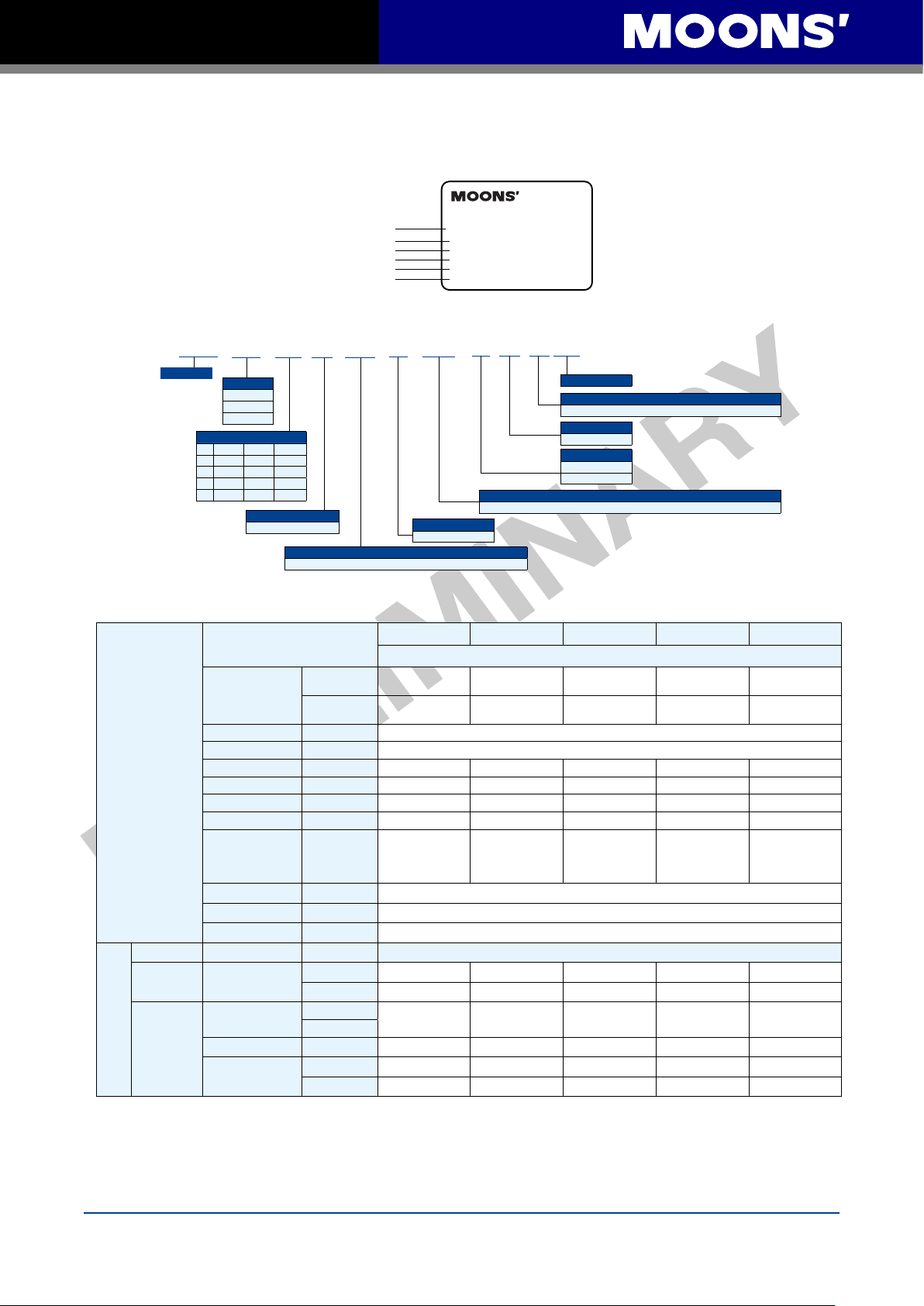
1.2.2 Drive Model Description
M2DV -
M2 Series AC Servo Drive
Current
Code
Continuous
Current (RMS)
1D8 1.75A 5.25A
3D0 3.00A 9.00A
4D5 4.50A 13.50A
□ □ □ 2 □
Boost
Current (RMS)
Voltage Code Input Voltage
2
Single/Three-Phases200~240VAC±10%, 50/60Hz
***
If Applicable
Communication
Type
S
Q
R
C
IP
E
5
Configuration Description Communication
Mini USB
Basic Type
Q Type
Q Type(Modbus/RTU Type)
CANopen Type
EtherNet/IP
eSCL
Type
Type
- - -
RS-232
RS-485
CANBus
EtherNet
EtherNet
4/29/2016
Rev. 1.0
M2 Quick Setup Guide Manaul
S M 04 01 A E4-K CD-N N V
**
1.3 Servo Motor Model Introduction
1.3.1 Motor Name Plate Description
Model NO.
Series NO.
Rated Torque
Input Current
Output Power
Rated Speed
1.3.2 Motor Model Description
Servo Motor
Frame Size
04-40mm
06-60mm
08-80mm
Motor Length
□40□60□
01 50W 200W
02 100W 400W
03 750W
04 1000W
80
Winding
A: 320 VDC(240 VAC)
E4: 2500 ppr Optical Encoder and Shared Commutation Tracks
1.4 Servo Drive and Servo Motor Combinations
Specificatioon
2500ppr Increment
Encoder
(9PIN AMP connector)
Rated Speed
Maximum Speed
Rated Torque
AC Servo Motor
Pulse&Direction
Type
AC
Servo
Drive
Fieldbus Type
Maximum Torque
Rated Current
Maximum Current
Rotor Inertia
Insulation Class Class B
Protection Class IP65(except shaft through hole and cable end connetor)
il Seal With Oil seal
O
USB Mini
RS-485
CAN CANopen
Ethernet
Without Brake
With Brake
(RPM) 3000
(RPM) 6000
(N•m)
(N•m)
(A)
(A)
2
Kg•m
Basic Type
Q Type
SCL
Modbus RTU
Ethernet/IP
eSCL
AC SERVO MOTOR
Model NO.SM0602AE2-KCD-NNV15
Ser NO. 12110027
Rated Torque 1.27N
Input 3ØAC 220V 2.8A
Ouput 400W
Rated Rev. 3000r/min
CD: 300mm (12") Shielded Cables with AMP 4 Pin, 6-7 Amp Motor Connector.
Shaft
K: Standard Keyway
Ecoder
50W 100W 200W 400W 750W
SM0401AE4-KCD-
NNV09
SM0401AE4-KCD-
BNV09
0.19 0.32 0.64 1.27
0.48 0.93 1.9 3.8 6.9
0.7 1.2 1.5 2.75 4.5
1.75 3.6 4.5 8.3 13.5
0.0232×10-4
*0.0298×10
(*With Brake)
M2DV-1D82S M2DV-1D82S M2DV-1D82S M2DV-3D02S M2DV-4D52S
M2DV-1D82Q M2DV-1D82Q M2DV-1D82Q M2DV-3D02Q M2DV-4D52Q
M2DV-1D82R M2DV-1D82R M2DV-1D82R M2DV-3D02R M2DV-4D52R
M2DV-1D82C M2DV-1D82C M2DV-1D82C M2DV-3D02C M2DV-4D52C
M2DV-1D82IP M2DV-1D82IP M2DV-1D82IP M2DV-3D0
M2DV-1D82E M2DV-1D82E M2DV-1D82E M2DV-3D02E M2DV-4D52E
-4
SM0402AE4-KCD-
SM0402AE4-KCD-
0.0428×10
*0.0494×10
(*With Brake)
NNV09
BNV09
·m
Code
Connections
-4
-4
Shaft Seal
SM0602AE4-KCD-
NNV09
SM0602AE4-KCD-
BNV09
0.272×10
*0.326×10
(*With Brake)
V: Shaft seal shipped with motor, but not placed on shaft
Thermal Protector
N: No Protector
Brake Option
N: No Brake
B: 24VDC Brake
Motor Model Numbers
SM0601AE4-KCD-
NNV09
SM0601AE4-KCD-
BNV09
-4
-4
0.165×10
*0.22×10
(*With Brake)
Drive Model Numbers
SM0803AE4-KCD-
NNV09
SM0803AE4-KCD-
BNV09
2.4
-4
-4
2IP M2DV-4D52IP
0.89×10
*0.97×10
(*With Brake)
-4
-4
Rev. 1.0
4/29/2016
6
M2 Quick Setup Guide Manaul
2 Installation
2.1 Storage Conditions
Some Storage suggestions are followed:
• Correctly packaged and store in a clean and dry ,avoid direct sunlight
• Store within an ambient temperature range of -20℃ to +65
• Store within a relative humidity rang of 10% to 85% and non-condensing
• Don
’t store in a place subjected to corrosive gasses
2.2 Installation Conditions
The operation ambient conditions are followed:
• Temperature range of 0℃ to 50℃. If the ambient tempera
45℃, please install the drive in a well-ventilated location
The ambient temperature of servo dive for long-term reliability should be under 45℃.
• The servo drive and motor will generate heat. If they are installed in a control panel, please
ensure sufficient space around the units for heat dissipation.
• Operation within a relative humidity rang of 5%to
• The vibration lower than 5.88m/s
2
, 10-60Hz(Do not continuously use the drive for along time at
resonance point.)
• Don
’t mount the servo drive and motor in a location subjected to corrosive gasses or
flammable gases, and combustibles.
• Please mount the servo drive and motor to a indoor electric control cabinet without liquid and
direct sunlight
• Don
’t mount the servo drive and motor in a location subjected to airborne dust.
85% and non-condensing
℃
ture of servo drive is greater than
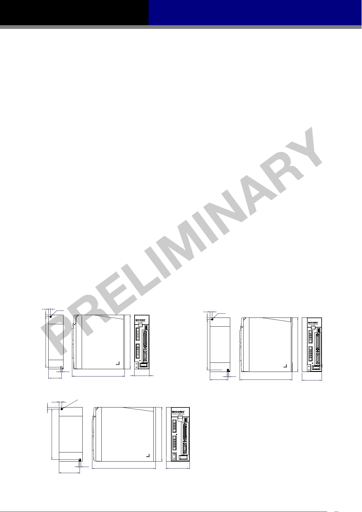
2.3 Drive Dimensions(Unit: mm)
50W、100W、200W Type
6
Ø5
5
140
5
35.5
750W Type
7.5
5
Ø5.2
140
145
150
41
150
400W Type
6
Ø5
5
140
49.5
150
5
145
55
57.5
5.2
176
65
7
Rev. 1.0
4/29/2016
M2 Quick Setup Guide Manaul
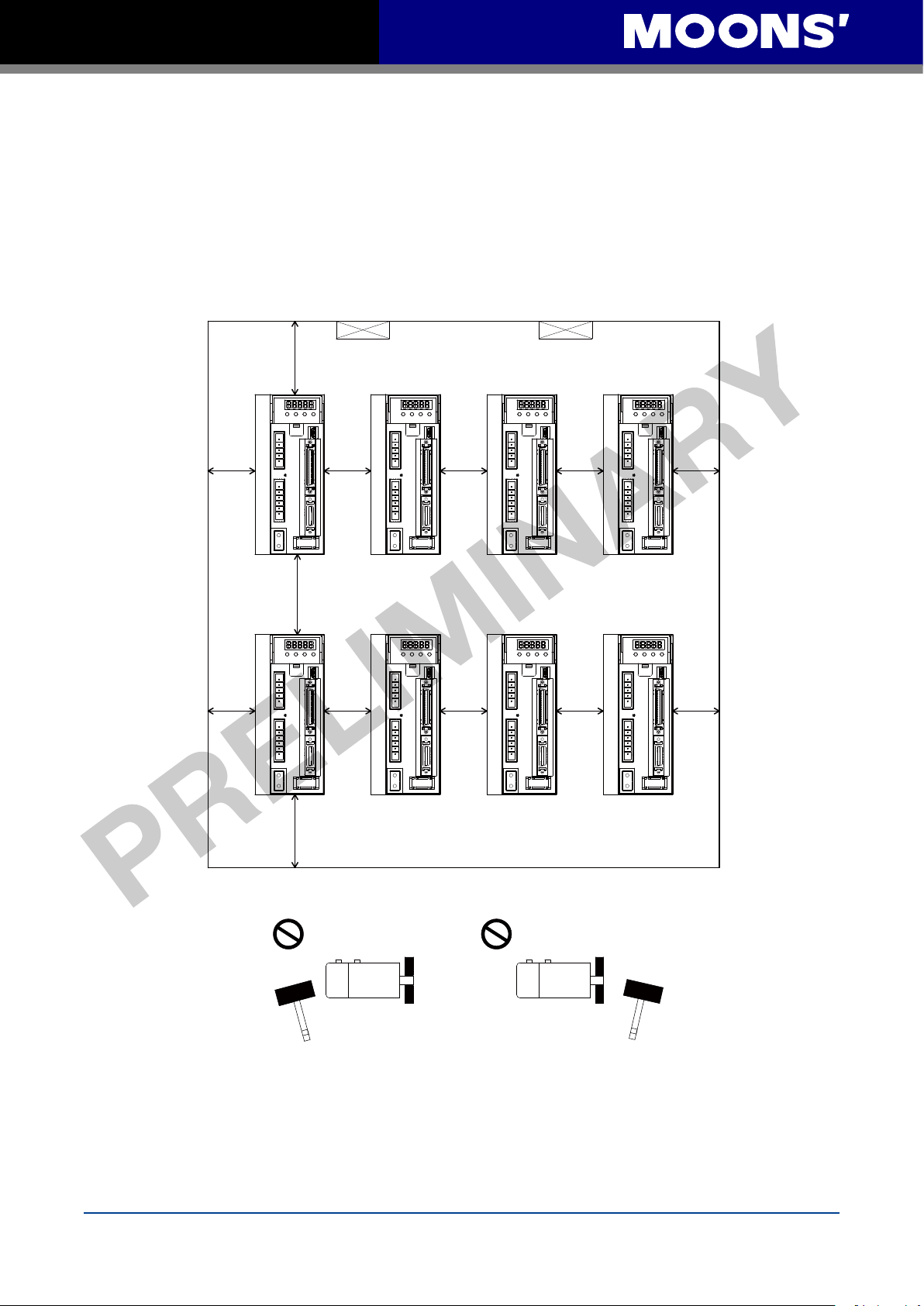
2.4 Installation Space
• Incorrect installation may result in a drive malfunction or premature failure of the drive and or
motor. Please follow the guidelines in this manual when installing the servo drive and motor.
• The M2 servo drive should be mounted perpendicular to the wall or in the control panel.
• In order to ensure the drive is well ventilated, ensure that the all ventilation holes are not
obstructed and suffic
the control panel.
• Please ensure grounding wires are securely connected
ient free space is given to the servo drive,and a cooling fan is mounted in
100mm
80mm
Fan Fan
10mm 10mm 10mm20mm
10mm 10mm 10mm20mm 20mm
20mm
100mm
2.5 Motor Installation
• Don't strike the motor when mounting as the motor shaft or encoder may be damaged.
• Don't use cables soaked in water or oil.
• Avoid a stress application to the cable outlet and connecting portion by bending
• Please use flexible cables when using cable carrier, make sure the minimum cable bending
radius is 200mm
• The shaft through hole and cable end connector is not IP65 design. Make sure to preve
liquid or oil into the motor from these parts.
Rev. 1.0
4/29/2016
8
nt any
M2 Quick Setup Guide Manaul
3 Connections and Wiring
3.1 Connecting to Peripheral Devices
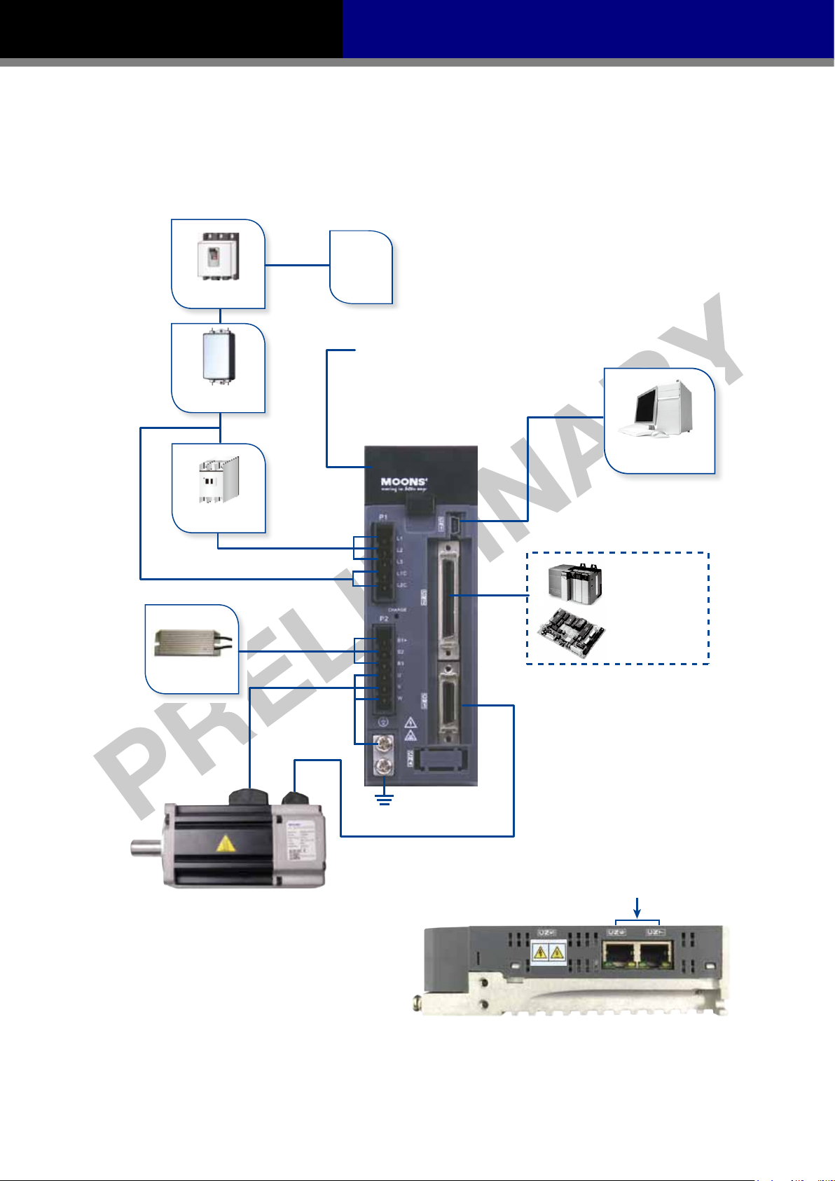
3.1.1 System Conguration
AC Power
Non Fuse Breaker
LED Display
The 5 digit,7 segment LED displays the
diver status and faults.
Operation Panel
Line Filter
(optional)
Function keys are used to perform status
display,monitor and diagnostic,function
and parameter setting.
Electromagnetic
Contactor
Regeneration
Absorbing Resistor
Main Power Input
Control Power Input
Motor Power Cable
Ground (PE)
Motor Feedback Cable
USB communication Port
(CN1)
PLC
Motion Control Card
I/O Interface
Used to connect PLC ,motion card
and other controllers.
Line Filter
AC Power Part No. Vendor
Single phase 240Vac 10ET1 Tyco
Three phase 240Vac DF300-10A-01 Dephir
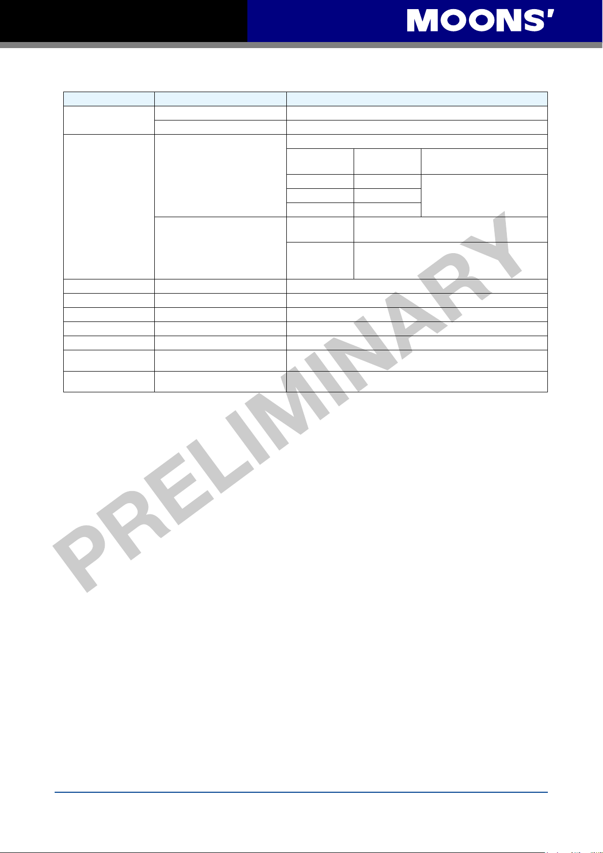
CANBus, RS-485, Ethernet
Communication Port
9
Rev. 1.0
4/29/2016
M2 Quick Setup Guide Manaul
3.1.2 Servo Drive Connectors and Terminals
Terminal Identification Description Details
P1
P2
CN1 Communication Port User to connect personal computer
CN2 I/O Connector Used to connect external controllers.
CN3 Encoder Feedback Connector Used to connect encoder of servo motor.
CN4 Reserved
CN5 Reserved
CN6
CN7
L1、L2、L3 Used to connect three-phase AC main circuit power
L1C、L2C Used to connect single-phase AC for control circuit power
Used to connect servo motor
U、V、W
B1+、B2、B3
Regenerative resister terninals
RS-485/CANopen
*RS-2
32 Communication Port
RS-485/CANopen
Communication Port
Terminal
Symbol
U Red
V Yellow
W Blue
Internal
Resister
External
Resister
RJ45 connector, Daisy Chain, Used for RS-485/CANopen
*RS-232 Communication Port (-Q Type Only)
RJ45 connector, Daisy Chain, Used for RS-485/CANopen
Wire color Description
Ensure the circuit is closed between B2 and
and the circuit is open between B1+ and B3.
Ensure the circuit is open between B2 and B3,
and connect the external regenerative resister
between B1+ and B2.
Communication
Connecting to three-phase
motor main circuit cable
B3,
3.1.3 Connections and Wiring Notes
• Please ensure grounding wires are securely connected, wires with more than 2.0mm2 on width
is recommended.
• Grounding method must be single point grounding.
• Ensure L1/L2/L3 and
specification range.
• Ensure U/V/W are following the order of RED/YELLOW/BULE. Wrong connections will cause
motor stop rotation, or wrong rotatory directions.
• Isolation transformer or EMI filter is recommended on drive
safety and improve its anti-interference level.
• Please setup a emergence stop circ
• Please DO NOT touch drive or motors
powered off. There are electrical charge components in the circuitry. Therefore, even power is
off, there might still be hazardous voltages within the circuitry, before its total discharge.
• Install the encoder cables in a separate conduit from the
noise. Separate the conduits by 30cm (11.8inches) above.
• Use multi-stranded twisted-pair wires or multi-core shielded-pair wires for signal, encoder
feedback cables.
L1C/L2C are correctly wired, and voltage supply are within the
’s power supply to ensure drive’s
uitry to switch off the power supply when fault occurs.
’s connector terminals 5 minutes after drive and motor is
motor power cables to avoid signal
• The maximum length of signal input/output cable is 5m, and the maximum length of encoder
(PG) feedback cables is 15m
Rev. 1.0
4/29/2016
10

M2 Quick Setup Guide Manaul
3.2 Wiring Methods
220V AC servo drive supports single phase or three phase wiring method. Three phase wiring
method for 750W or above drives is recommended.
3.2.1 Single-Phase Power Supply Connection(AC220V)
L N E
MCCB
NF
P_on
P_off
E_stop
MC
Alarm
MC
Use external
regeneration resistor
B1+
B2
B3
regeneration resistor
Use Internal
MC
M2 Servo Drive
L1
L3
L1C
L2C
B1+
B2
B3
P1
P2
U
V
W
CN3
Alm_R
Red
Yellow
Blue
Yellow/Green
Ground
Encoder
Alm_R
3.2.2 Three-Phase Power Supply Connection(AC220V)
R
MCCB
NF
E
T
S
P_on
P_off
E_stop
MC
M
Encoder
24VDC
Alarm
MC
Use external
regeneration resistor
B1+
B2
B3
Use Internal
regeneration resistor
MC
M2 Servo Drive
L1
L2
L3
L1C
L2C
B1+
B2
B3
11
Alm_R
Red
U
Yellow
V
P2
W
CN3
Blue
Yellow/Green
Ground
Encoder
M
Encoder
Alm_R
24VDC
Rev. 1.0
4/29/2016
 Loading...