

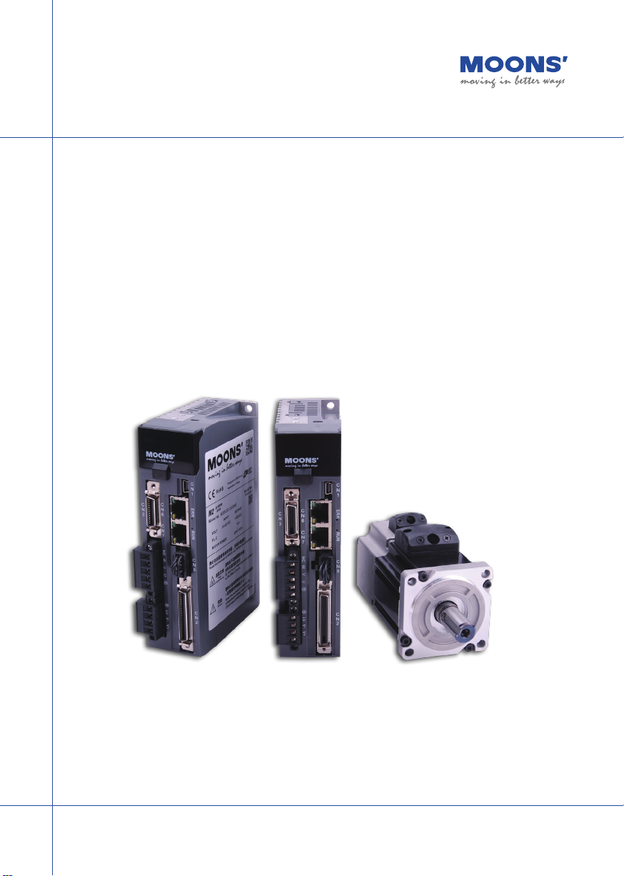
M2 Series DC Servo System
Quick Setup Guide Manual
SHANGHAI AMP&MOONS’ AUT OMATION CO.,LTD.
1
Rev. 1.0
Introduction
About This Manual
This manual describes the M2DC Servo Drive.
It provides the information required for installation, conguration and basic operation of the M2DC
series servo drive.
This document is intended for persons who are qualied to transport, assemble, commission, and
maintain the equipment described herein.
Documentation Set for the M2DC Series Servo Drive
This manual is part of a documentation set. The entire set consists of the following:
• M2DC Quick Start Guide: Basic setup and operation of the drive
• M2DC Hardware Manual: Hardware installation, conguration and operation
• M Servo Suite Software User Manual: How to use the M Servo Suite software
Safety
Only qualied persons may perform the installation procedures. The following explanations are for
procedures that must be observed in order to prevent harm to people and damage to property.
The M2DC utilizes hazardous voltages. Be sure the drive is properly grounded.
Before you install the M2DC, review the safety instructions in this manual.
Failure to follow the safety instructions may result in personal injury or equipment damage.
Safety Symbols
Safety symbols indicate a potential for personal injury or equipment damage if the recommended
precautions and safe operating practices are not followed.
The following safety-alert symbols are used on the drive and in the documentation:
Caution Warning - Dangerous voltage
Protective earth Caution - Hot surface
2
Rev. 1.0
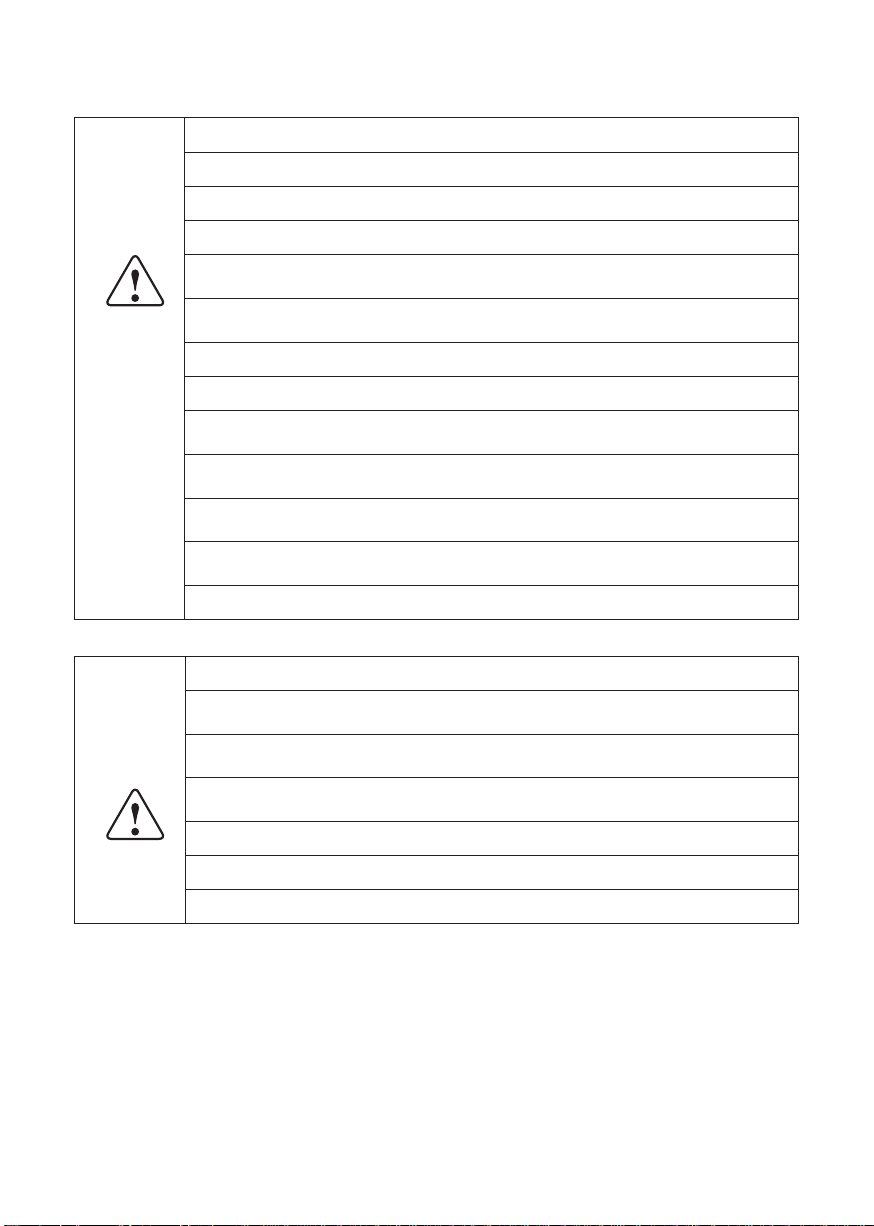
Safety Instructions
Installation
DO NOT subject the product to water, corrosive or ammable gases, or combustibles.
DO NOT use the motor in a place subject to excessive vibration or shock.
Never connect the motor directly to the AC power supply.
DO NOT use cables soaked in water or oil.
DO NOT extrude or pull off the cable, or damage the cables as electrical shocks or damage
may result
DO NOT block the heat dissipating holes. Prevent any metal lings from dropping into the drive
during installation.
DO NOT switch the power supply on and off repeatedly.
DO NOT touch the rotating shaft when the motor is running.
DO NOT strike the motor when during indtallation as the motor shaft or encoder may be dam-
aged.
To prevent accidents, the initial trial run for the servo motor should be conducted under a noload condition (separate the motor from its couplings and belts).
Starting system operation without rst matching the correct parameters may result in servo
drive or motor damage, or damage to the mechanical system.
DO NOT touch the drive heat sink, motor, or the regeneration resistor during operation as they
may be very hot.
DO NOT hold the motor by the cable during transportation or installation.
Wiring
DO NOT connect any power supply to the U, V, or W terminals.
Install the encoder cable in a separate conduit from the motor power cable to avoid signal
noise.
Use multi-stranded twisted-pair wires or multi-core shielded-pair wires for signal and encoder
cables.
A hazardous voltage charge may still remain in the drive even after the power has been removed - Do not touch the terminals when the charge led is still lit.
Please observe the specied voltage(s).
Make sure both the drive and the motor connect to a class 3 ground.
Please ensure the grounding wires are securely connected before power up.
Standards Compliance
The M2DC Series Servo drive has been designed according to standards:
Electromagnetic compatibility Electrical Safety: Low voltage directive
Standard EN 61800-3 (2004) Standard IEC 61800-5-1 (2007)
3
Rev. 1.0

Table of Contents
1. Product Description ...................................................................................................................6
1.2 Servo Drive Model Introduction .........................................................................................6
1.2.1 Drive Name Plate Description ..................................................................................6
1.2.2 Drive Model Description ...........................................................................................6
1.2.3 Drive specications ..................................................................................................7
1.3 Servo Motor Model Introduction ........................................................................................8
1.3.1 Motor Name Plate Description .................................................................................8
1.3.2 Motor Model Description ..........................................................................................8
2 Installation ..................................................................................................................................9
2.1 Storage Conditions ............................................................................................................9
2.2 Installation Conditions .......................................................................................................9
2.3 Drive Dimensions (Unit: mm) ............................................................................................9
2.4 Installation Space ............................................................................................................10
2.5 Motor Installation .............................................................................................................11
3. Connections and Wiring ..........................................................................................................12
3.1 Connecting to Peripheral Devices ...................................................................................12
3.1.1 System Conguration ............................................................................................12
3.1.2 Servo Drive Connectors and Terminals .................................................................13
3.1.3 Connections and Wiring Notes ..............................................................................13
3.1.4 Wiring Methods for P1 Power Supply Connector ..................................................14
3.2 Wiring to the P2 Connector ............................................................................................15
3.2.1 Motor Power Cable Conguration ................................................................................15
3.2.2 Motor Power Cable Connector(-CD Winding ,6Amps) ..........................................15
3.2.3 Motor Extension Cable Wiring Diagram .................................................................16
3.2.4 Motor Power Cable Connector(-CF Winding,10Amps) ..........................................16
3.2.4.1 PIN Assignment ............................................................................................16
3.2.4.2 Motor Extension Cable Wiring Diagram .......................................................17
3.3 Encoder Connector CN3 .................................................................................................17
3.3.1 Motor Encoder Feedback Cable Conguration ......................................................17
3.3.2 Layout of CN3 Connector ......................................................................................18
3.3.3 Connection to Motor Encoder ................................................................................18
3.3.4 Specications of Encoder Connector .....................................................................19
3.3.5 Motor Encoder Extension Cable Wiring Diagram .................................................20
3.4 Electromagnetic Brake ....................................................................................................21
3.4.1 Wiring Diagram ......................................................................................................21
3.4.2 Brake Motor ...........................................................................................................21
3.4.3 Timing Charts of the Electromagnetic Brake .........................................................22
3.5 Regeneration Resistor ....................................................................................................22
3.6 Recommended Cable Specications ..............................................................................22
3.7 Connecting to the Host Computer - CN1 ........................................................................23
3.8 Input and Output Signal Interface Connector - CN2 .......................................................23
3.8.1 Input and Output Interface Specications and Diagram ........................................23
3.8.2 Layout of CN2 Connector ....................................................................................23
3.8.3 Signal Description of Connector CN2 ....................................................................24
3.8.3.1 Input Signals .................................................................................................25
3.8.3.2 Input Function List ........................................................................................26
3.8.3.3 Output Signals ..............................................................................................27
3.8.3.4 Output Function List .....................................................................................28
3.8.4 Encoder Feedback Output .....................................................................................29
3.8.4.1 A/B/Z Connection Diagram ...........................................................................29
3.8.4.2 Z Phase Open Collector Output ...................................................................29
3.8.5 Input Signal Interface Connector, CN2 ..................................................................30
4
Rev. 1.0

3.8.5.1 Position pulse signal input ............................................................................30
3.8.5.2 Analog Signal Input For Velocity And Torque Mode .....................................32
3.8.5.3 High Speed Input Ports X1, X2, X3, X4 ........................................................33
3.8.5.4 General Digital Input X5, X6, X7, X8 ............................................................35
3.8.5.5 X9, X10, X11, X12 Inputs with common COM Port ......................................37
3.8.6 CN2 Output Signal Specication ...........................................................................38
3.9 STO Connector ...............................................................................................................39
3.9.1 Safety Precautions .................................................................................................39
3.9.2 STO Input/Output Signals ......................................................................................39
3.9.2.1 STO Internal Circuit Diagram .......................................................................39
3.9.2.2 CN5 Connector diagram ...............................................................................40
3.9.2.3 STO Signal Denition ...................................................................................40
3.9.2.4 STO Connection Diagrams ..........................................................................41
4. Display and Operation .............................................................................................................42
4.1 Control Panel Description ...............................................................................................42
4.2 Mode Switch Control .......................................................................................................43
4.3 LED display description ...................................................................................................45
4.3.1 Decimal Point And Negative Sign Description .......................................................45
4.3.2 Parameter View Setting .........................................................................................45
4.3.3 Parameter Save Setting .........................................................................................46
4.3.4 Point To Point Motion Mode ..................................................................................46
4.3.5 Jog Mode ...............................................................................................................46
4.3.6 Control Panel Lock ................................................................................................46
4.4 Status Monitoring Selection Mode ..................................................................................47
4.5 Function Control Mode ....................................................................................................49
4.5.1 Function Mode Description ....................................................................................50
4.5.2 Operation Flow Chart .............................................................................................51
4.6 Parameter Setting Mode .................................................................................................52
4.6.1 Parameter Setting Description ...............................................................................52
4.6.2 Parameter Editing Examples .................................................................................53
4.7 Control Panel Lock ..........................................................................................................54
4.8 Warning And Fault Display ..............................................................................................54
5. Preoperational mode ...............................................................................................................56
5.1 Inspection Before Trial Run ............................................................................................56
5.2 Trial Run Procedure ........................................................................................................57
5.3 Motor Conguration .........................................................................................................58
5.3.1 Using the Drive Control Panel for conguration .....................................................58
5.3.2 Using M Servo Suite Software for conguration ....................................................59
5.4 Operations of JOG Mode ................................................................................................60
5.5 Conguration by Personal Computer ..............................................................................61
6.Drive alarm causes and solutions.............................................................................................62
7. Position Mode ..........................................................................................................................66
7.1 Digital Pulse Position Mode Connection Diagram...........................................................66
7.2 Velocity Mode Connection Diagram ................................................................................67
7.3 Analog Torque Mode Connection Diagram .....................................................................68
5
Rev. 1.0
1. Product Description
1.1 System Checklist
A complete and workable M2DC servo system should include the following parts:
A matched servo drive and servo motor (see section 2.4 for recommended combinations)
1. A power cable with a 4-PIN connector to connect P1 (V+, V-, AUX+) to supply power to the
drive
2. A motor cable with a 5-PIN connector to supply the servo motor with power from the drive and
to connect a regenerative resistor through P2 (U, V, W)
3. An encoder cable with a 26-PIN connector to connect port CN3 for encoder feedback
4. A mini USB cable to connect port CN1 to a PC for communication
5. An I/O cable with a 50-PIN connector to connect port CN2 for I/O
6. Cables with RJ-45 connectors to connect ports CN6 and CN7 for RS-485 or CANopen com-
munication
1.2 Servo Drive Model Introduction
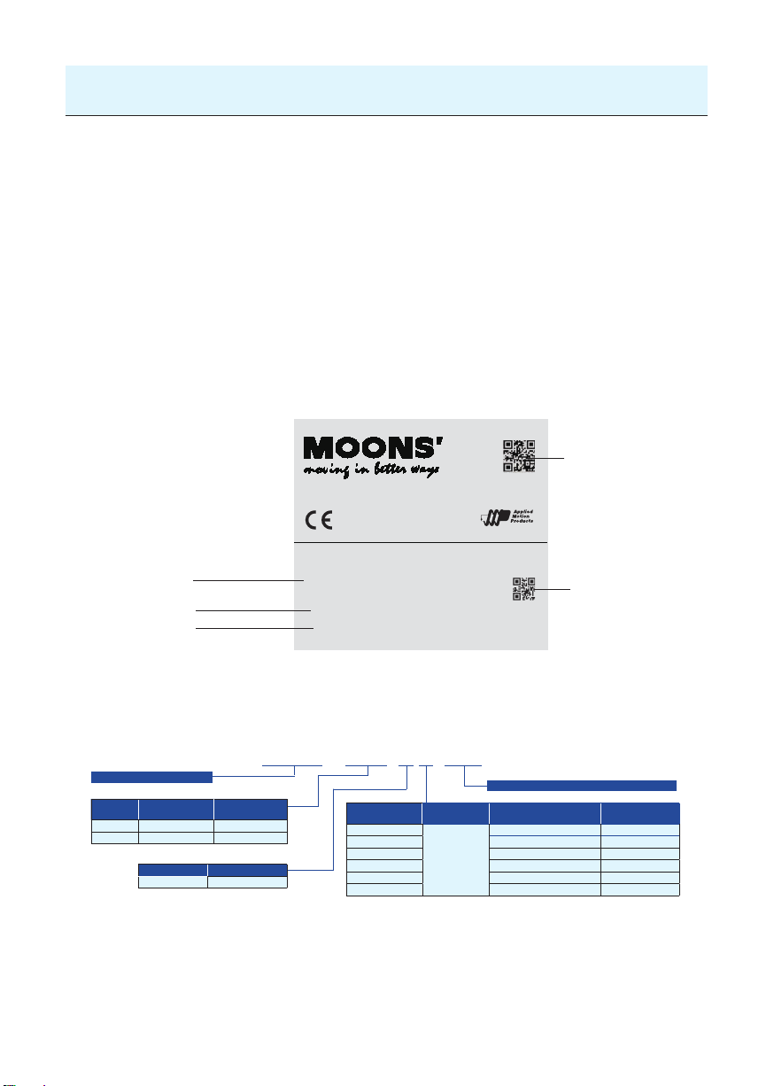
1.2.1 Drive Name Plate Description
www.moons.com.cn
Model No.
Voltage
Output Current
1.2.2 Drive Model Description
M2DC - 6D0 5 S
M2 Series DC Servo Drive
Current
Continuous
Code
Current (RMS)
6D0 6.0A 18.0A
10D 10.0A 30.0A
Voltage Code Input Voltage
5 10-60VDC
Boost
Current (RMS)
RoHS
DC SERVO
M2
DRIVE
Model No. M2DC-6D05X
VOLT. 0-60VDC20-60VDC
F.L.C
Designed in California by
Assembled in China
INPUT
Communication
Code
S
Q Q Type RS-232
R Q Type (Modbus/RTU) RS-485
C CANopen Type CANBus
D eSCL Type Ethernet
IP EtherNet/IP Type Ethernet
6
OUTPUT
6 A
***
Configuration
type
Mini USB
Serial No.
09450001
Serial No.
Customized Specification (If Applicable)
Description
Basic Type - - - - - -
Communication
type
Rev. 1.0
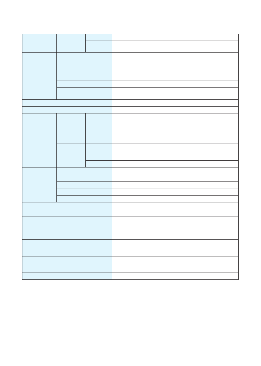
1.2.3 Drive specications
Input Power
Environment
I/O
Communication
Regeneration Resistor Built-in regenerative resistor (external resistor is also enabled)
M2DC-6D0
M2DC-10D
Control method IGBT PWM Sinusoidal wave drive
Encoder feedback 2500 ppr optical encoder with shared commutation signals
Control
Signal
Analog signal Input 2 inputs (12Bit A/D: 2 input)
Pulse signal
Front panel 4 keys (MODE, UP, DOWN, SET), LED (5-digit)
Dynamic Brake Built-in
Control modes
Control inputs
Control outputs
Certication RoHS, EN 61800-3:2004, EN 61800-5-1:2007
Main Circuit 20 - 60VDC
Control
Circuit
Temperature
Humidity Both operating and storage: 10 to 85%RH or less
Altitude Lower than 1000m
Vibration
Input
Output 6 optically isolated multi function outputs, 5-24VDC, 20mA
Input
Output 3 line driver outputs, 1 open collector output
Mini USB Connection with PC or 1 : 1 communication to a host.
RS-232 RS-232 communication
RS-485 RS-485 communication & Modbus/RTU
CANbus CANopen communication
Ethernet EtherNET/IP or eSCL
10- 60VDC
Ambient temperature: 0°C to 50°C (if the ambient temperature of
the servo drive is greater than 40°C, please install the drive in a
well-ventilated location)
Storage temperature: -20°C to 65°C
5.88m/s2 or less, 10 to 60Hz
(do not use continuously at resonance frequency)
8 optically isolated multi function inputs, 5-24VDC, 20mA
2 optically isolated multi function high speed inputs, 5-24VDC,
20mA
1 photocoupler input compatible with both line driver I/F and open
collector I/F
1 line receiver input compatible with line driver I/F
(1) Position mode (2) Analog velocity mode (3) Analog position
mode (4) Position mode (5) Velocity change mode (6) Command torque mode (7) Command velocity mode
(1) Servo-ON input (2) Alarm clear input (3) CW/CCW Limit (4)
Pulse& Direction or CW/CCW input (5) Gain Switch (6) Control
mode Switch (7) Pulse Inhibition (8) General Input
(1) Alarm output (2) Servo-Ready output (3) External brake release (4) Speed arrival output (5) Torque arrival output (6) Tach
out (7) General output (8) Position arrival output
7
Rev. 1.0
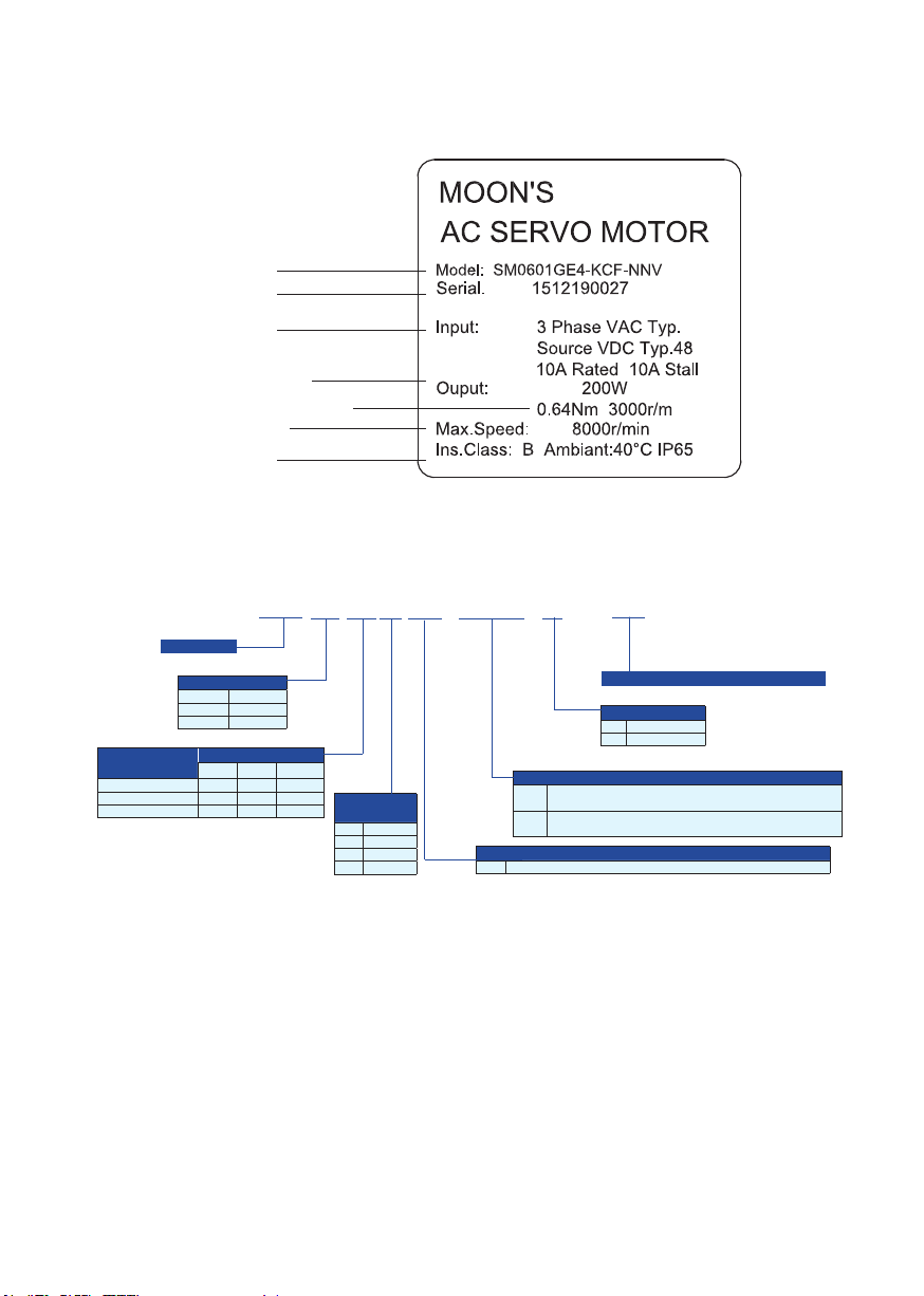
1.3 Servo Motor Model Introduction
1.3.1 Motor Name Plate Description
Mode NO.
Series NO.
Input
Ouyput Power
Rated Torque,speed
Max. Speed
Ins.Class
1.3.2 Motor Model Description
Servo Motor
Frame Size
04 40mm
06 60mm
08 80mm
Wattage code
01 60W 200W
02 100W 400W 300W
03 550W
Motor Length (mm)
40 60 80
SM06 02 F E4-KCF-NNV
300mm Shielded Cable with non-Sealed Connectors -
Input
Voltage(DC)
E 80V
F 60V
G 48V
H 36V
KCD
For Winings up to 6.5Amps
300mm Shielded Cable with non-Sealed Connectors -
KCF
For Winings 6.6 to 12.5 Amps
E4 2500 ppr optical encoder with shared commutation signals
**
Customized Specification (If Applicable)
Brake Option
N No Brake
B 24VDCBrake
Shaft and Lead/Connector Style
Feedback
8
Rev. 1.0
2 Installation
2.1 Storage Conditions
Store properly packaged in a clean and dry environment,away from direct sunlight
Store in an ambient temperature range of -10°C to +85°C
Store where the relative humidity range is 10% to 85% with non-condensing
DO NOT store in a place exposed to corrosive gases
2.2 Installation Conditions
Temperature range of 0°C to 50°C. If the ambient temperature of the servo drive is greater than 40°C,
please install it in a well-ventilated location.
The ambient temperature of the servo drive for long-term reliability should be less than 45°C.
The servo drive and motor will generate heat; if they are installed in a control panel, please
ensure sufcient space around the units for heat dissipation.
Operate where the relative humidity range is 10% to 85% and non-condensing
Install where the vibration is lower than 5.88m/s2, 10Hz-60Hz (DO NOT use the drive for extended
periods of time at the resonance point.)
DO NOT install the servo drive and motor in a location subjected to corrosive or ammable gases, or
combustibles.
Install the servo drive and motor in an indoor electric control cabinet.
DO NOT install the servo drive and motor in a location subject to airborne dust.
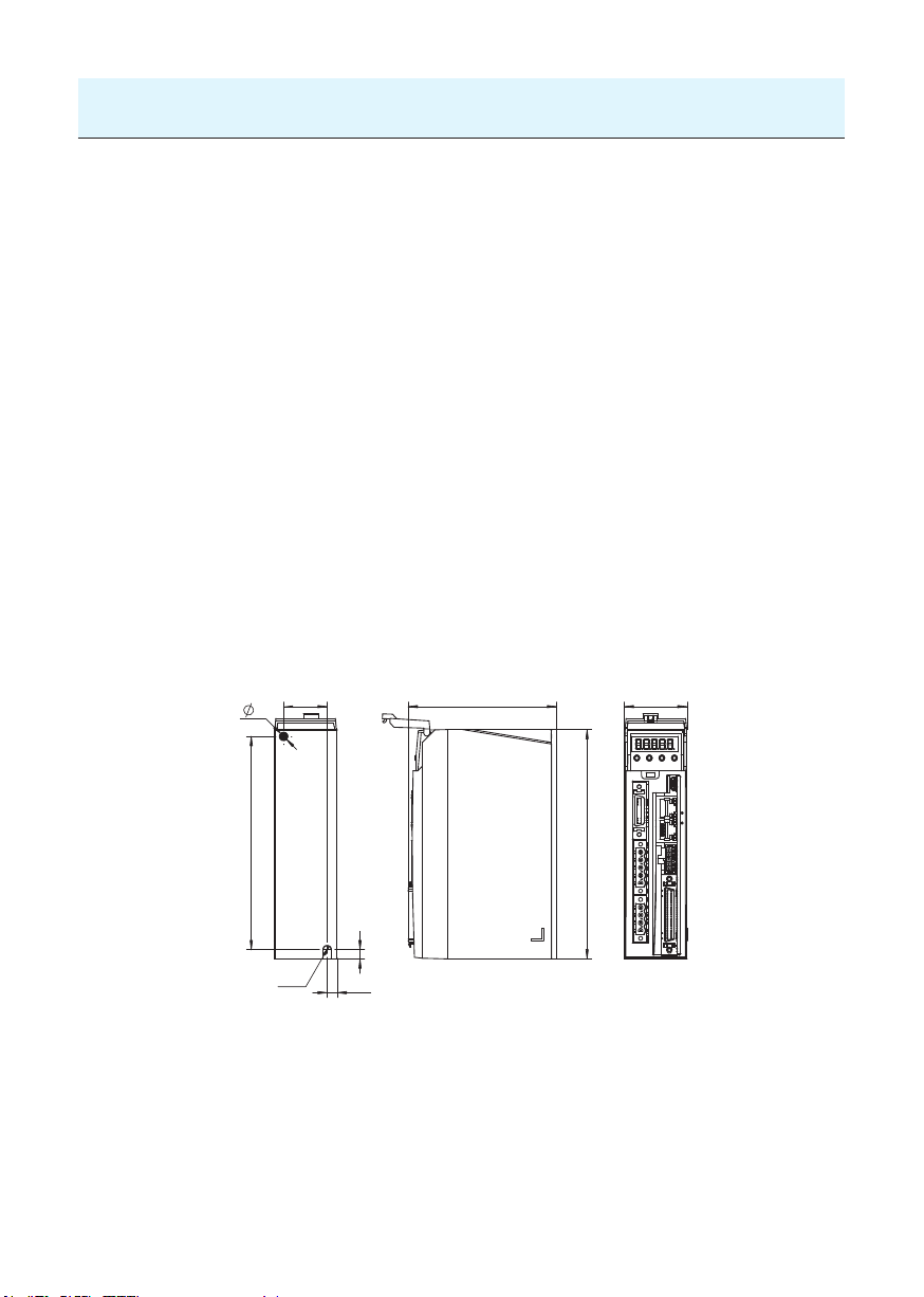
2.3 Drive Dimensions (Unit: mm)
5
139.5
28.5
R2.5
6
6.5
97
150
9
41
Rev. 1.0
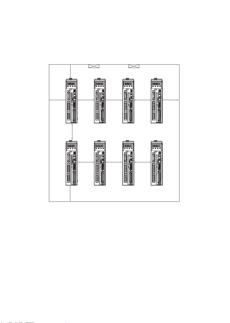
2.4 Installation Space
Incorrect installation may result in a drive malfunction or premature failure of the drive and/or motor.
Please follow the guidelines in this manual when installing the servo drive and motor.
The M2DC servo drive should be installed perpendicular to the wall or in a control panel.
In order to ensure the drive is well ventilated, make sure ventilation holes are not obstructed, there is
sufcient free space around the servo drive, and a cooling fan is mounted in the control panel.
Ensure the grounding wires are securely connected
20mm
100mm
80mm
100mm
Fan Fan
10mm
10mm
10mm 10mm
10mm
20mm
10mm
10
Rev. 1.0

2.5 Motor Installation
DO NOT strike the motor when installing it as the motor shaft or encoder may be damaged.
DO NOT use cables that have been soaked with water or oil.
Avoid a stress application to the cable outlet and connecting portion by bending.
Use exible cables when using a cable carrier, and make sure the minimum cable bending diameter is
200mm.
The shaft through hole and cable end connector are not IP65 designed. Be careful to prevent any
liquid or oil from getting into the motor at these areas.
11
Rev. 1.0
3. Connections and Wiring
3.1 Connecting to Peripheral Devices
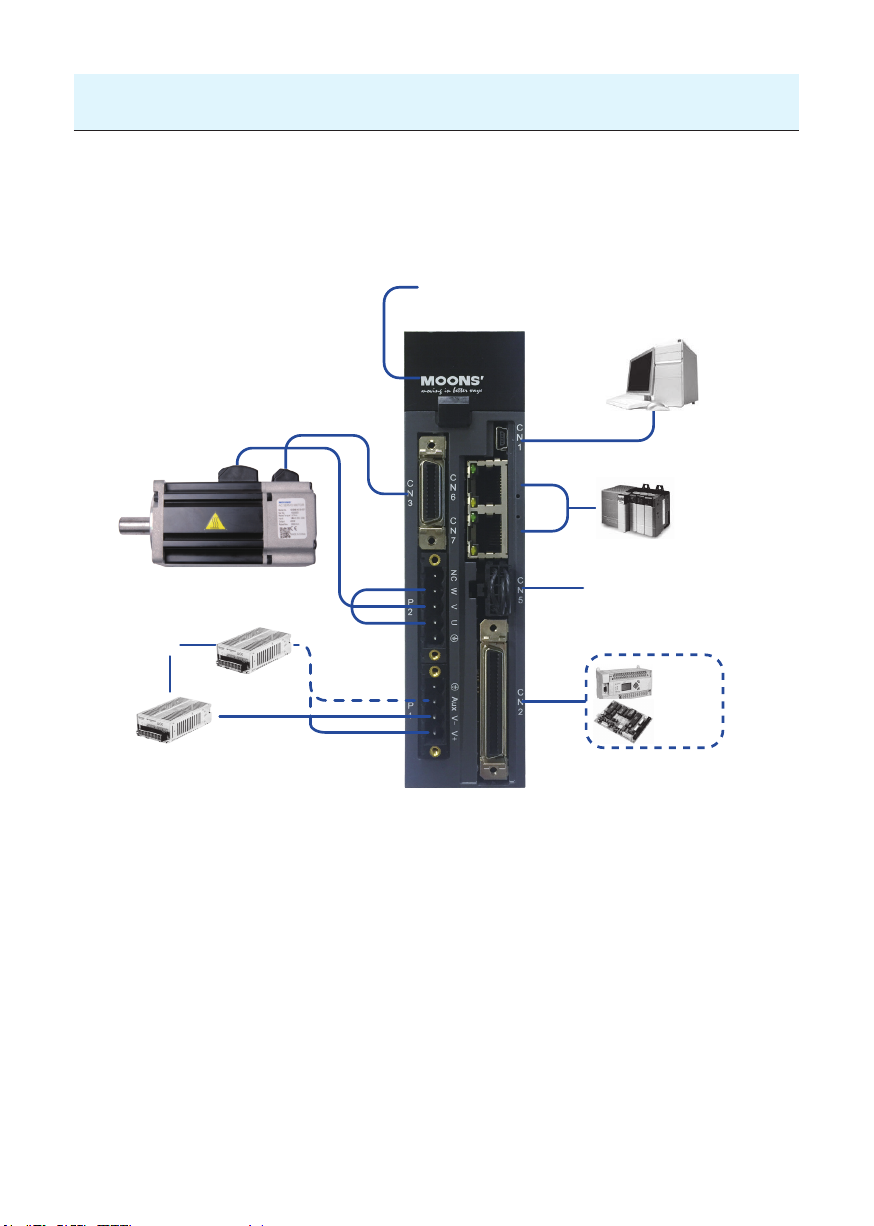
3.1.1 System Conguration
LED Display
The 5 digit, 7 segment LED displays
the diver status and faults.
Operation Panel
Function keys are used to perform status
display, monitor and diagnostic,
function and parameter setting.
PC/Configuration
AC
Source
AC-DC Power Supply
Motor Feedback Cable
Motor Power Cable
AUX Power
MAIN Power
USB Cable
CANBus, RS-485, Ethernet
Communication Port
STO Interface
PLC
Motion
Control Card
I/O Interface
Used to connect PLC, motion card
and other controllers.
12
Rev. 1.0

3.1.2 Servo Drive Connectors and Terminals
Terminal
Identication
Description Details
P1
P2
CN1 Communication Port
CN2 I/O Connector
CN3
Encoder Feedback Connector
CN4 Reserved
CN5 STO Connector
RS-485/CANopen Port
CN6
Ethernet Port
*RS-232 Communication
Port
RS-485/CANopen Port
CN7
Ethernet Port
Communication Port
V+, V-
AUX
U, V, W
Used to connect DC main circuit power
Used to connect an auxiliary circuit power
Ground
Used to connect servo motor
Terminal
Symbol
Wire color Description
U Red
Connects to servo motorV Yellow
W Blue
Ground
User to connect PC
Used to connect external controllers
Used to connect servo motor encoder
Used to connect STO (Safe Torque Off)
RJ45 connector, Daisy Chain, Used for RS-485/CANopen/
Ethernet
*RS-232 Communication Port (-Q Type Only)
RJ45 connector, Daisy Chain, Used for RS-485/CANopen /
Ethernet
Communication
3.1.3 Connections and Wiring Notes
• Ensure the grounding wires are securely connected. Wire with a cross section of more than
2.0mm2 is recommended.
• Grounding method must be single point grounding.
• Ensure V+ and V- are correctly wired, and voltage supplies are within the specied range.
• Auxiliary power V+ connects to drive AUX connector, auxiliary power V- connects to drive V-.
• Ensure U/V/W is wired following the order of RED/YELLOW/BLUE.
• An isolation transformer or EMI lter is recommended on drive’s power supply to ensure the
drive’s safety and improve its anti-interference level.
• Set up emergency stop circuitry to switch off the power supply when a fault occurs.
• DO NOT touch the drive or motor’s connector terminals for at least 5 minutes after the drive and
motor have been powered off. There are electrical charge components in the circuitry which discharge
slowly.
• Install the encoder cables in a separate conduit from the motor power cables to avoid signal
noise. Separate the conduits by at least 30cm (11.8 inches).
• Use multi-stranded twisted-pair wires or multi-core shielded-pair wires for the encoder feedback
cables.
• The maximum length of the signal input/output cable should be no more 5 meters, and the en-
coder (PG) feedback cable no more than 15 meters.
13
Rev. 1.0
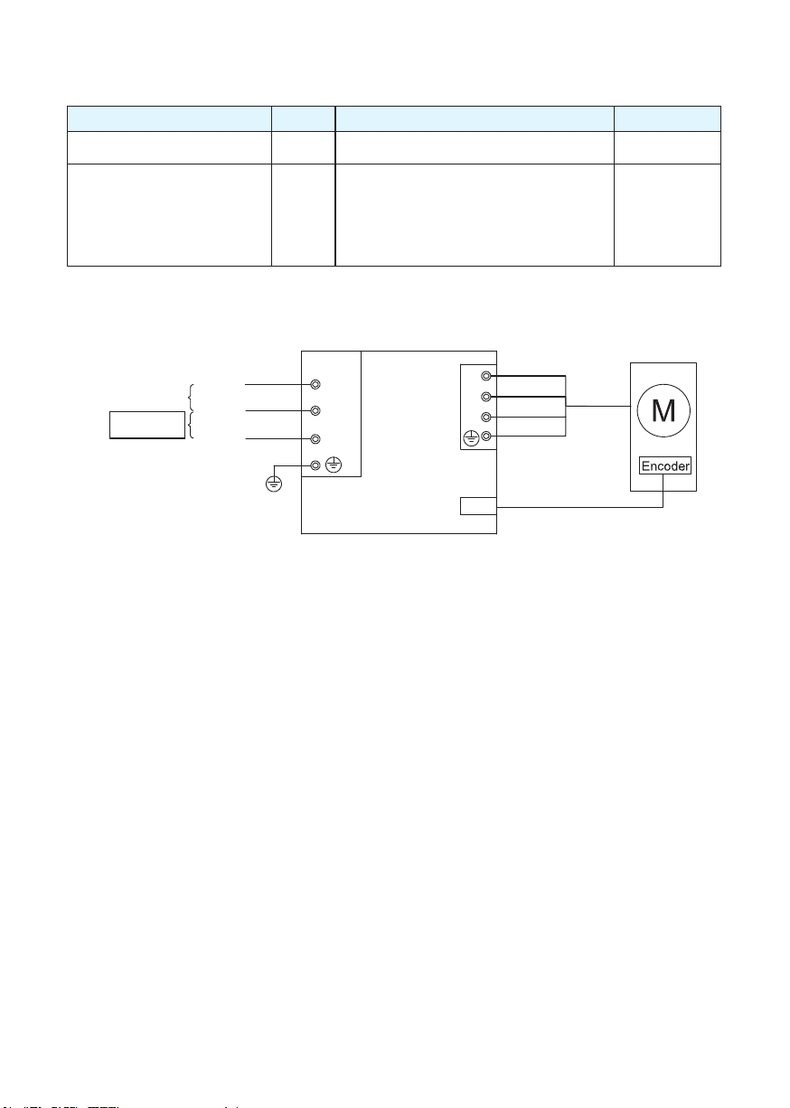
3.1.4 Wiring Methods for P1 Power Supply Connector
Power for the M2DC servo drives comes from 2 different sources
Pin Function Input Power
Main power supply V+, V- Drive’s main power input 20 - 60VDC
When the main power supply is off, the AUX
power will keep the logic circuitry alive, allow-
Control circuitry power/auxiliary
Main power
18 - 70VDC
Control circuitry/
auxiliary power
*
power
DC in+
DC GND
DC in+
AUX, V-
ing the drive to remember its current state data
(motor position, etc.) The motor is then able
to resume operation without running a homing
routine while the main power is switch-on
again.
M2DC Servo Drive
red
P2
U
V
W
CN3
yellow
blue
yellow/green
Encoder connector
V+
VAUX
P1
10 - 60VDC
*Note: For optimized motion performance, make sure the main power input voltage is higher
than the motor winding voltage by at least 2VDC.
14
Rev. 1.0
3.2 Wiring to the P2 Connector
Please follow Chart 5.3 before power up.
3.2.1 Motor Power Cable Conguration
P2 interface of the drive
W
V
U
Motor power
extension cable
connector
Motor
lead wire
connector
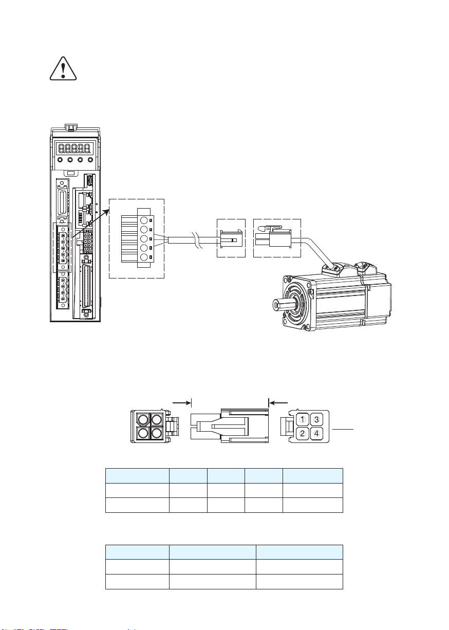
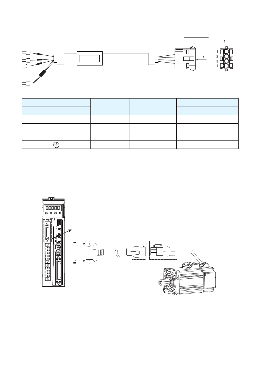
3.2.2 Motor Power Cable Connector(-CD Winding ,6Amps)
A PIN Assignment
A B
View A View B
Pin 1 2
Signal U V
Color Red Yellow
3 4
W PE
Blue Yellow/Green
B Motor Connector Specications
Type Motor side (plug) Plug-in (housing)
Housing AMP 172167-1 AMP 172159-1
Terminal AMP 170360-1 AMP 170362-1
15
Rev. 1.0
3.2.3 Motor Extension Cable Wiring Diagram
Housing: 172159-1(AMP)
Terminal: 170362-1(AMP)
Drive side (P2)
5452571(Phoenix) AMP 172159-1
U U Red 1
V V Yellow 2
W W Blue 3
Signal Color
PE Yellow/Green 4
Motor side (housing)
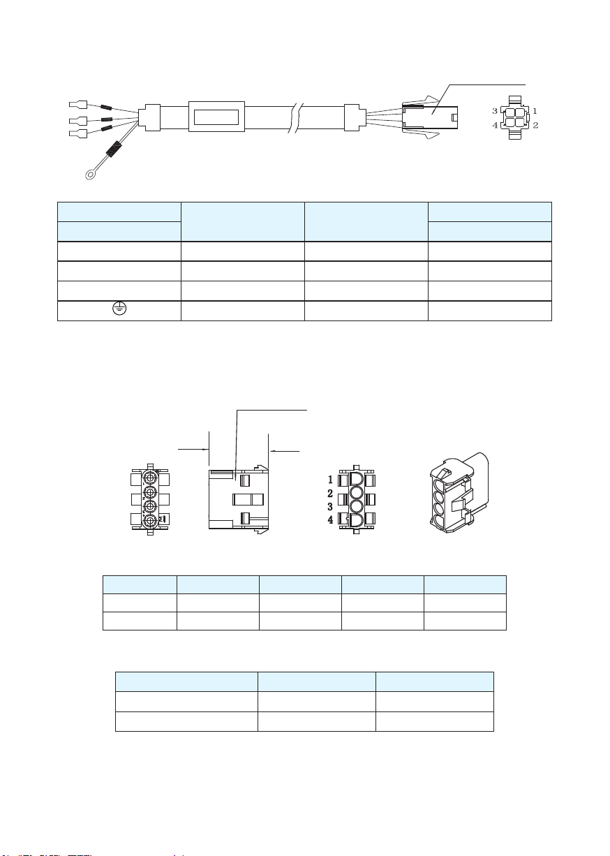
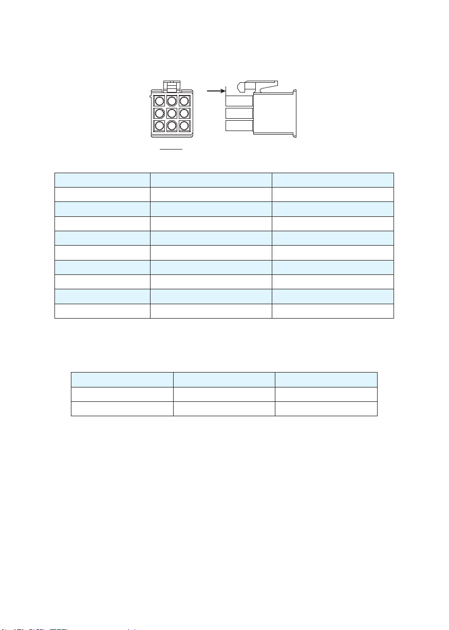
3.2.4 Motor Power Cable Connector(-CF Winding,10Amps)
3.2.4.1 PIN Assignment
Cover:350780-1(AMP)
Pin:350536-1(AMP)
A
A side view B side view
Pin 1 2
Signal U V
Color Red Yellow
B
3 4
W PE
Blue Yellow/Green
Motor Connector Specications
Type Motor side (plug) Plug-in (housing)
Housing AMP 350-779-1 AMP 350780-1
Terminal AMP 350218-1 AMP 350536-1
16
Rev. 1.0
3.2.4.2 Motor Extension Cable Wiring Diagram
Housing :350780-1
Terminal:350536-1
Drive side (P2)
5452571 (Phoenix) AMP 350780-1
Signal Color
U U Red 1
V V Yellow 2
W W Bleu 3
PE Yellow/Green 4
Ensure U/V/W is wired in the order of RED/YELLOW/BLUE.
3.3 Encoder Connector CN3
3.3.1 Motor Encoder Feedback Cable Conguration
CN3 interface of the drive
Encoder
extension cable
connector
Motor encoder
connector
Motor side (housing)
17
Rev. 1.0
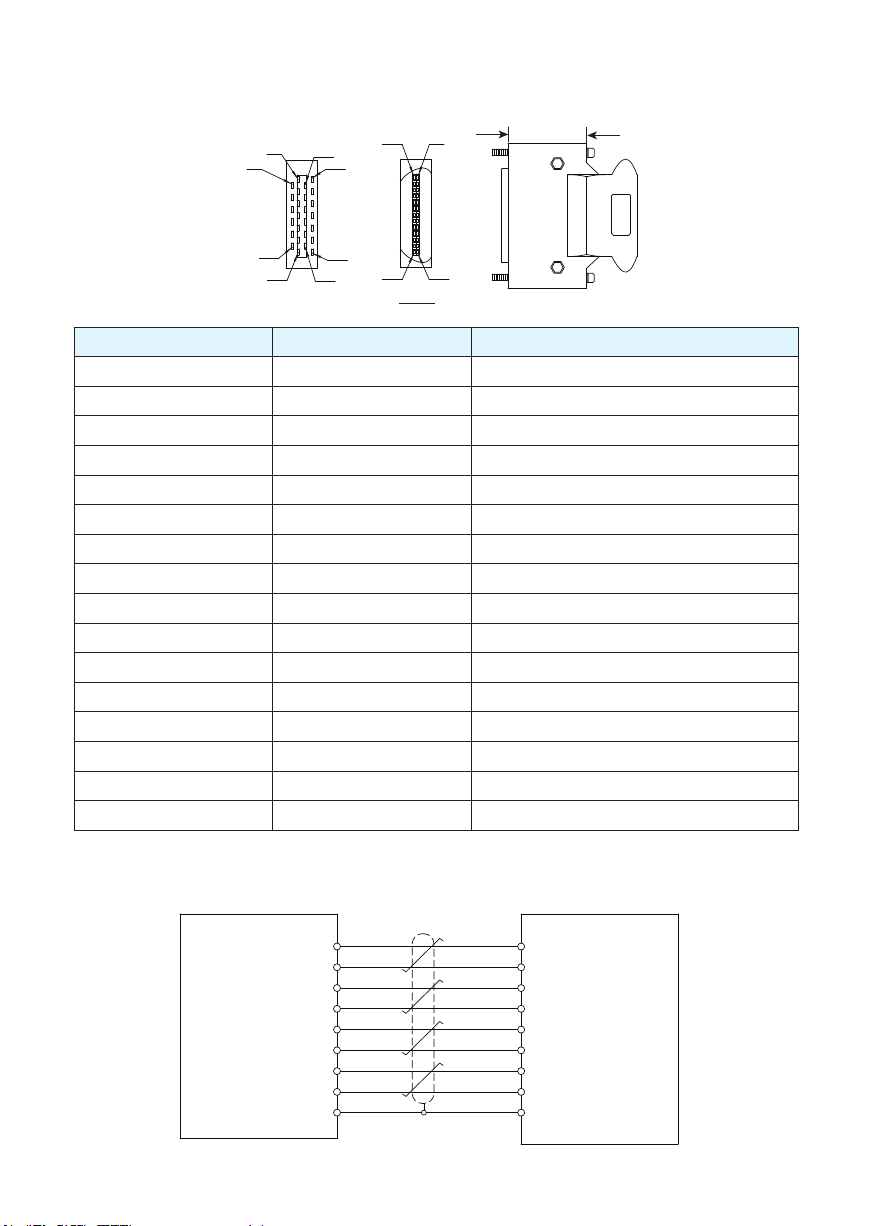
3.3.2 Layout of CN3 Connector
Motor Encoder
Servo Drive CN3
A+
1
A-
4
B+
2
B-
5
Z+
3
Z-
6
+5V
7
GND
8
Shield
9
1
14
2
15
3
16
11
24
26
A+
AB+
BZ+
Z+5V
GND
Shield
A
1
15
25
14
26
14
26
13
View A
1
2
12
13
View B
B
Pin NO. Symbol Description
1 A+ Encoder A+
2 B+ Encoder B+
3 Z+ Encoder Z+
4 U+ Hall U+
5 W+ Hall W+
6 U- Hall U-
7 W- Hall W-
11 Encoder +5V Encoder power supply +5V
13 Encoder +5V Encoder power supply +5V
14 A- Encoder A-
15 B- Encoder B-
16 Z- Encoder Z-
17 V+ Hall V+
19 V- Hall V24 GND Encoder power supply ground
26 Shield Shield
3.3.3 Connection to Motor Encoder
Connect to 2500ppr Increment Encoder (9PIN AMP connector)
18
Rev. 1.0
3.3.4 Specications of Encoder Connector
A. -E4 Encoder Connector PIN Assignment
A
1 3
7
9
View A
PIN# Signal Colour
1 U+/A+ Blue
2 V+/B+ Green
3 W+/Z+ Yellow
4 U-/A- Yellow/Black
5 V-/B- Green/Black
6 W-/Z- Yellow/Black
7 +5V Red
8 GND Black
9 Shield Shield
NOTE: The HALL signal U/V/W ONLY appears for short time after the encoder is powered on,
it will then covert to A/B/Z signals.
B. -E4 Encoder Connector Specications
Type Motor Plug Housing for the motor
Housing AMP 172169-1 AMP 172161-1
Terminal AMP 770835-1 AMP 770834-1
19
Rev. 1.0
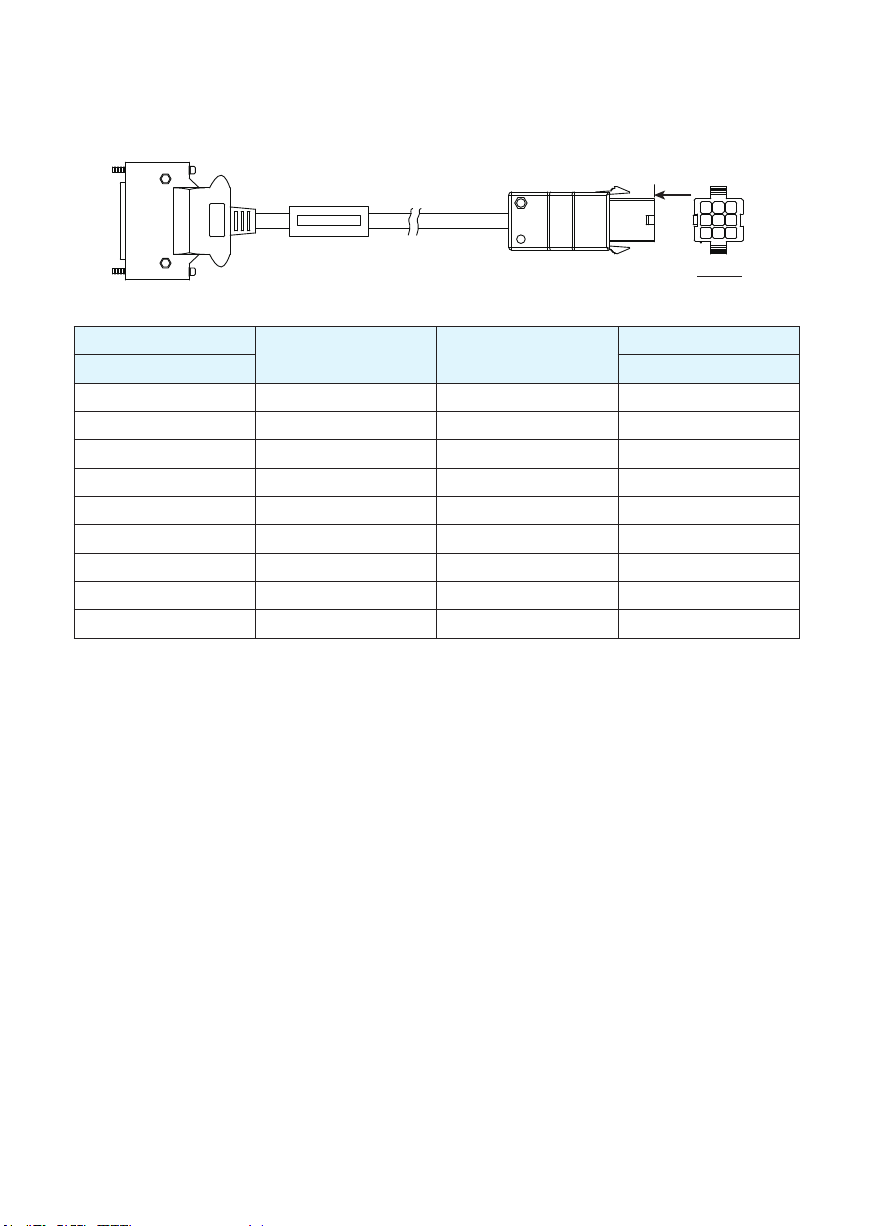
3.3.5 Motor Encoder Extension Cable Wiring Diagram
-E4 Encoder Encoder Cable Diagram
Connect to drive
Connect to Motor
A
1
3
View A
7
9
Drive Side
TYCO 3-22322346-1 AMP 172161-1
Signal Color
Housing for the motor
1 A+/U+ Blue 1
2 B+/V+ Green 2
3 Z+/W+ Yellow 3
14 A-/U- Yellow/Black 4
15 B-/V- Green/Black 5
16 Z-/W- Yellow/Black 6
11 +5V Red 7
24 GND Black 8
26 Shield Shield 9
20
Rev. 1.0
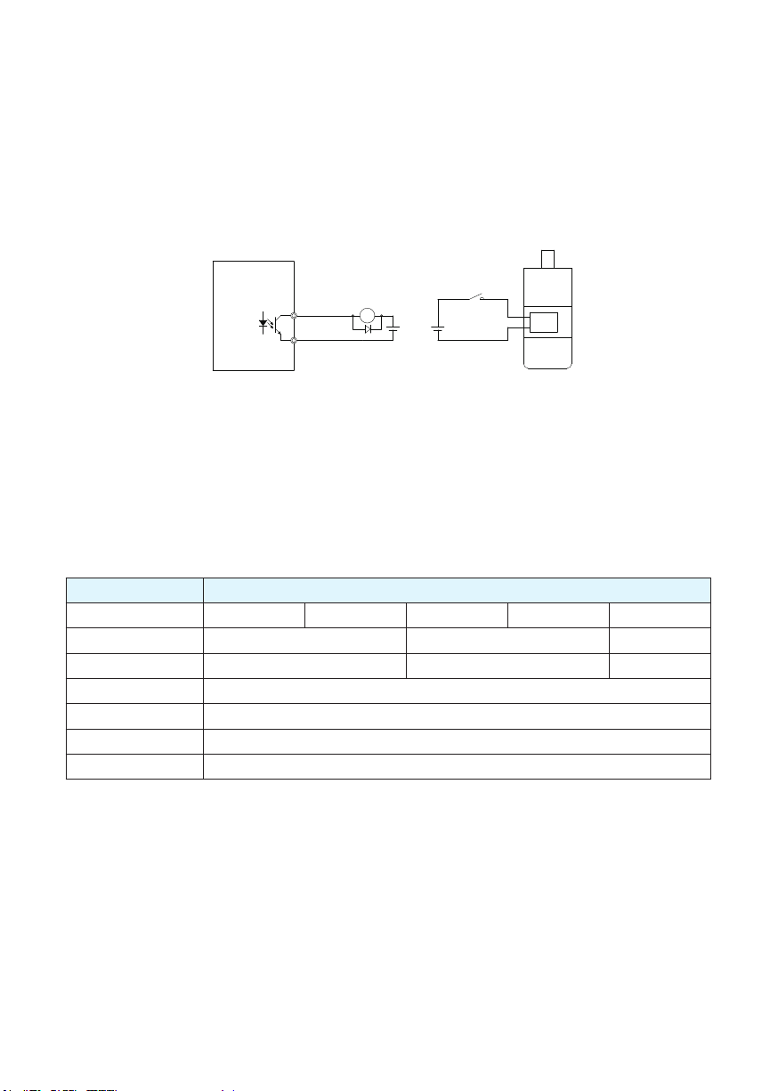
3.4 Electromagnetic Brake
When the motor drives the vertical axis, a brake should be used to hold and prevent the load from
fallingby gravity when the power is removed.
NOTE: Use only a servo motor brake for holding a load when the motor is disabled or the power
is off. Never use a servo motor brake to stop a load in motion. This may cause damage to the
servo motor.
3.4.1 Wiring Diagram
Servo Drive
Relay
Brake
Brake+
Brake-
Relay
R
24VDC 24VDC
3.4.2 Brake Motor
● When no power is applied to the electromagnetic brake, it is in a locked position. Therefore, the mo-
tor shaft will not be able to rotate.
● The brake coil has no polarity.
● During the brake/release action, you might hear a clicking sound. This is normal and does not affect
the use of brake.
● Specications of the brakes are as follows:
Motor Power
Type 60W 100W 200W 400W 550W
Holding torque (N•m) 0.35 2 4.5
Working current (A) 0.25 0.38 0.61
Rated voltage (V) 24V±10%
Release time <25ms
Engage time <25ms
Release voltage (V) Release voltage18.5VDC
21
Rev. 1.0

3.4.3 Timing Charts of the Electromagnetic Brake
In order to prevent damage to the brake, there are delay sequences during the brake operation.
Please be cautious with brake operation sequence.
ON
OFF
ON
OFF
ON
OFF
ON
OFF
ON
OFF
ON
OFF
Brake Release Delay
P-69 Setting
Brake Engage Delay
P-70 Setting
Servo on Input
Motor Active
Brake Signal
Brake Action
Motion Command
Actual Motion
Brake engage/disengage delay time can be set through M Servo Suite software, or on the drive
directly through the P function: P-69 (BD) or P-70 (BE).
3.5 Regeneration Resistor
In M2DC series servo drives, there is a pre-installed 20W regeneration resistor. In some applications,
the pre-installed regeneration resistor might not be enough to absorb all foldback current. In these
cases, a larger wattage regeneration resistor needs to be connected externally, to prevent drive over
voltage warnings.
3.6 Recommended Cable Specications
● Select wires with sufcient allowance for parameters such as operating current and ambient
temperature.
● Recommended wire selections are as follows:
Servo Drive And Corresponding Motor Model
M2DC-6D05 1.5 (AWG15) .75 (AWG18)
M2DC-10D5 2.5 (AWG13) 1.25 (AWG16)
22
Wire Width mm
2
(AWG)
V+/V- U/V/W
Rev. 1.0

3.7 Connecting to the Host Computer - CN1
Port CN1 is used to connect the drive with a PC. Use M Servo Suite software to set the control mode,
change parameter values, use the auto-tuning function, etc.
PIN Symbol Function
1 +5V +5V Power Supply
2 D- Data -
3 D+ Data +
4 — Reserved
5 GND Ground
3.8 Input and Output Signal Interface Connector - CN2
3.8.1 Input and Output Interface Specications and Diagram
Port CN2 on the M2DC series servo drives is used for input/output signals. Details are shown in table
below:
Inputs
Digital Signal
Outputs
I/O
Signals
Analog Signal Inputs 2 Analog inputs, with 12 bit resolution
Inputs
Pulse Signal
Outputs
8 Congurable optically isolated general inputs, 5-24VDC, 20mA
4 Congurable optically isolated high speed inputs
4 Congurable optically isolated general outputs, max 30VDC, 20mA
1 Alarm output, max 30VDC, 20mA
1 motor brake control output, max 30VDC, 20mA
2 optically isolated high speed inputs 500KHz (open collector)
2 high speed differential inputs 2MHz
4 high speed encoder feedback outputs (3 line driver A/B/Z, and 1 open
collector output Z)
3.8.2 Layout of CN2 Connector
1
2
27
26
24
50
25
49
View B
50 25
View A
126
A
B
23
Rev. 1.0

3.8.3 Signal Description of Connector CN2
44
PULSH1
45
PULSH2
SIGNH1
SIGNH2
X1+
X1-
X2+
X2-
X3+
X3-
X4+
X4-
X5+
X5-
X6+
X6-
X7+
X7-
X8+
X8-
COM
X9
X10
X11
X12
46
47
3
4
5
6
29
31
35
34
8
2
9
1
39
38
12
32
7
1.5K
26
1.5K
1.5K
27
1.5K
1.5K
28
1.5K
1.5K
30
1.5K
Position
Command
High Speed
Pulse Input
STEP/CW
DIR/CCW
Enable
Alarm Reset
Limit Sensor
Limit Sensor
Gain Select
Control mode Switch
Dividing Switch
SPD0
SPD1
SPD2
Analog Input
16
+
-
+
-
15
18
17
37
36
11
10
40
41
14
13
42
43
33
21
22
48
49
23
24
19
15
20
25
50
ANA1
Speed Command
DGND
ANA2
Torque Command
DGND
Y1+
Alarm Output
Y1-
Y2+
Motor Brake
Control Output
Y2-
Y5+
Servo-on Status Output
Y5-
Y6+
In Position Output
Y6-
Y3
Torque Reached Output
Servo Ready Output
Y4
Velocity Reached Output
OUT-
AOUT+
AOUT-
BOUT+
BOUT-
ZOUT+
ZOUT-
CZ
DGND
+10V User
User_GND
FG
Encoder
Feedback
Output
24
Rev. 1.0

3.8.3.1 Input Signals
The M2DC series servo drive has 12 programmable digital inputs as well as 2 analog inputs.
Each of the inputs can be specied with different functions via the parameter settings. The functions
are as follows:
● Specied function signals: i.e. STEP/DIR signal, motor enable/disable signals.
● General purpose signal: In velocity mode, torque mode, Q program mode, or SCL mode, it is used
as general purpose signal with no specied functions.
Signal Symbol Pin NO. Details
X1+ 3
X1
X1- 4
X2+ 5
X2
X2- 6
X3
X4
X5
X6
X7
X8
X9 X9 26
X10 X10 27
X11 X11 28
X12 X12 30
COM COM 7 X9-X12 COM point
X3+ 29
X3- 31
X4+ 35
X4- 34
X5+ 8
X5- 2
X6+ 9
X6- 1
X7+ 39
X7- 38
X8+ 12
X8- 32
This input has three functions:
● Accept STEP pulse input such as STEP signals, CW pulse, A pulse in position
mode
● Run/Stop input in torque or velocity mode
● General purpose input
This input has three functions:
● Accept STEP pulse input such as Direction signals, CCW pulse, B pulse in
position mode
● Direction input in torque or velocity mode
● General purpose input
● Enable/Disable input
● General purpose input
● Alarm reset input, used to reset drive alarm
● General purpose input
● Limit sensor input
● General purpose input
● Limit sensor input
● General purpose input
● Gain select input in pulse position mode
● General purpose input
● Switch control mode between main mode and second mode
● General purpose input
● Dividing switch, change the pulses per revolution for electronic gearing
● General purpose input
● Pulse inhibited input - ignores the pulse input when this input is activated in
position mode
● Speed selecting input 1 in change speed mode
● General purpose input
● Speed selecting input 2 in change speed mode
● General purpose input
● Speed selecting input 3 in change speed mode
● General purpose input
25
Rev. 1.0

High-
Speed
Pulse
Inputs
Analog
Input
Signal 1
Analog
Input
Signal 2
PULSH1 44
PULSH2 45
SIGNH1 46
SIGNH2 47
ANA1 16
DGND 15 Digital Ground for analog input
ANA2 18
DGND 17 Digital ground for analog input
High-speed pulse inputs (+5VDC line drive input), the maximum input frequency
2MHz.Three pulse commands available:
Pulse & Direction
●
CW Pulse and CCW Pulse
●
A Quadrature B pulse
●
(NOTE: DO NOT use with both X1 and X2)
In analog velocity control mode, the offset, dead band, and function of analog
input 1 can be set by M Servo Suite or parameters P-52, P-56 and P-61.
● Sets or requests the analog input gain that relates to motor position when the
drive is in analog position command mode
● Sets or requests the gain value used in analog velocity mode
General analog input in Q mode
●
● In analog torque control mode, the offset, dead band, and function of
input 2 can be set by M Servo Suite or parameters P-53, P-57 and P-61.
General analog input in Q mode
●
analog
3.8.3.2 Input Function List
1 2 3 4 5 6 7 8 9 10 11 12
Step ■
DIR ■
CW Limit ●
CCW Limit ●
Start/Stop ▲▼
Direction ▲▼
Servo enable ●
Alarm clear ●
Speed selection 1,2,3 ▲ ▲ ▲
Global gain selection ■
Control mode selec-
tion
Pulse encoder Reso-
lution selection
Pulse Inhabit ■
General Input ● ● ● ● ● ● ● ● ● ● ● ●
●
■
■– Position Mode ▲– Velocity Mode ▼ – Torque Mode ● – All Modes
26
Rev. 1.0

3.8.3.3 Output Signals
The M2DC series servo drive has 6 programmable digital output signals available; each of the outputs
can be specied with a different function via parameter settings.
Signal Symbol Pin NO. Details
This output has two functions:
● Alarm Output
● General purpose output
This output has two functions:
● Motor brake control output
● General purpose output
Torque Reached Output
Servo ready output
●
drive is ready to be controlled and without alarm
General purpose output
●
● Moving signal output - output signal when the dynamic posi-
tion error is less than the set value in position mode
● Velocity reach output - output signal when the actual speed
is the same as the target speed and the speed ripple less than
the ripple range
● General purpose output
enabled.
● General purpose outputY5- 41
I● n position signal output - output signal when in position,
and the position error is less than the set value in position
mode
● Tach out output - produces pulses relative to the motor position with congurable resolution
● General purpose output
● The encoder feedback phase A line drive output
● The encoder feedback phase B line drive output
● The encoder feedback phase Z line drive output
- output servo ready signal when the
Y1
Y2
Y3
Y4
Y5
Y6
Encoder pulse
feedback Output
+10V
Output
Y1+ 37
Y1- 36
Y2+ 11
Y2- 10
Y3+ 42
Y3- 33
Y4+ 43
Y4- 33
Y5+ 40 ● Servo-on Status output --output signals when the motor is
Y6+ 14
Y6- 13
AOUT+ 21
AOUT- 22
BOUT+ 48
BOUT- 49
ZOUT+ 23
ZOUT- 24
ZOUT 19 ● The encoder feedback phase Z output (open collector)
+10V User 20 +10VDC user, max 100mA
USER_GND 25 +10VDC user ground
27
Rev. 1.0

3.8.3.4 Output Function List
Output Pin Y1 Y2 Y3 Y4 Y5 Y6
Alarm Output ●
In Postion error ●
Dynamic Postion
error
Tach Out ●
Function
Brake ●
Torque Reach ●
Servo Ready ●
Servo-On Status ●
Velocity Reach ▲▼
General Output ● ● ● ● ● ●
■ – Position Mode ▲– Velocity Mode ▼ – Torque Mode ● – All Modes
■
28
Rev. 1.0

3.8.4 Encoder Feedback Output
The M2DC series servo drive can output encoder A/B/Z phase as differential output signals through
the line driver. The output signal is 5V, A/B signals are 10000 pulse/rev, Z signal is 1 pulse/rev.
The host must use the line receiver to receive these signals. Use twisted-pair wires for signal transfer.
3.8.4.1 A/B/Z Connection Diagram
Servo Drive
50
21
AOUT+
22
AOUT-
48
BOUT+
49
BOUT-
23
ZOUT+
24
ZOUT-
DGND
25
FG FG
Host Controller
A+
A-
B+
B-
Z+
Z-
DGND
NOTE: Please make sure the host controller and the servo drive are connected to a common
ground.
3.8.4.2 Z Phase Open Collector Output
On the M2 drives, encoder signal Z uses open collector output circuitry. Due to the narrow bandwidth
of encoder signal Z, please use high speed opto-coulper circuitry for the host receiver.
Servo Drive
24VDC
CZ
19
DGND
15
0VDC
29
Rev. 1.0

3.8.5 Input Signal Interface Connector, CN2
Open collector input
3
STEP+
4
STEP-
5
DIR+
6
DIR-
Controller
24VDC
0VDC
Controller
Controller
3.8.5.1 Position pulse signal input
The M2DC series servo has two high speed pulse intputs, STEP/DIR and PULSH/SIGNH. STEP/DIR
supports 5-24VDC, up to 500KHz open collector input signal or differential input signal through the line
driver. PULSH/SIGNH supports 5VDC, up to 2MHz with differential line driver input.
NOTE: STEP/DIR and PULSH/SIGNH CANNOT be used at the same time.
A. Open Collector Input Signal Diagram B. Differential Input Signal Diagram
DGND
FG FG
C. High Speed Differential Signal Input Diagram
Use ONLY 5V supply for PULSH/SIGNH input, DO NOT use 24V.
STEP+
STEP-
DIR+
DIR-
DGND
Differential Input
3
4
5
6
25
50
PULSH1
PULSH2
SIGNH1
SIGNH2
DGND
DGND
FG FG
30
Differential Input
44
45
46
47
25
50
Rev. 1.0

D. Pulse Input Description
STEP/DIR Pulse Input
When both STEP and DIR input signals are ON, the motor will rotate in one direction.
When STEP input signal is ON, and DIR input signal is OFF, the motor will rotate in the opposite direc-
tion.
The direction signal (DIR) can be congured via M Servo Suite software.
The following graph represents motor rotatation in CW direction when DIR input is ON.
Step
(PLS)
Direction
(DIR.)
Motor motion
High
Low
Single Pulse Input
Low
CW Direction
High
CCW Direction
CW/CCW Pulse
When Pulse input goes into X1, the motor will rotate in one direction.
When Pulse input goes into X2, the motor will rotate in the opposite direction.
Motor direction can be congured via M Servo Suite software.
CW pulse
CCW pulse
Motor motion
High
Low
High
Low
Dual Pulse Input
CW Direction
CCW
Direction
A/B Quadrature
In A/B Quadrature mode, the motor rotary direction is based on the leading signal between A and B.
Motor rotary direction can be congured via M Servo Suite software. Direction is dened by the leading input between X1/X2.
The following graph represents motor rotates in CW direction when X1 is leading X2.
Input A(X1)
Input B(X2)
A/B Quadrature Pulse Input
High
Low
High
Low
Motor motion
CWDirection
31
CCW
Direction
Rev. 1.0

3.8.5.2 Analog Signal Input For Velocity And Torque Mode
The M2DC series servo drive has 2 single ended analog inputs OR 1 differential analog input. The
input voltage range is -10V to +10V. Velocity and torque range can be congured via M Servo Suite
software.
Single Ended Analog Input
±10VDC
Differential Analog Input
Single Ended Analog Control Mode
ANA1(ANA2)
DGND
16(18)
15(17)
+
-
Host PC
D/A Output
DGND
Differential Analog Control Mode
16
15
18
17
DGND
+
-
+
-
32
Rev. 1.0

3.8.5.3 High Speed Input Ports X1, X2, X3, X4
High Speed Input Port
The M2DC has 4 optically isolated high speed digital inputs X1, X2, X3, and X4. These inputs allow
input voltage from 5VDC to 24VDC with maximum current of 20mA, and up to 500KHz. They can be
used for general purpose inputs, connecting sensor switch signals, PLC controllers or other types of
controller output signals.
NOTE: When the drive is in position mode, X1, X2 can ONLY be set as STEP/DIR signal.
When the drive is NOT in position mode, X1, X2 can be set as general purpose signals.
, X2, X3, X4 circuits are as follows:
X1
3
X1+
4
X1-
5
X2+
6
X2-
29
X3+
31
X3-
35
X4+
34
X4-
33
Rev. 1.0

High Speed Input Connection Diagrams
HOST controller
+5-24VDC
Power
0V
5-24VDC
X1\2\3\4+
X1\2\3\4-
0VDC
Host Sink Mode
X1\2\3\4+
X1\2\3\4-
Relay Or Switch
HOST controller
5-24VDC
0VDC
5-24VDC
NPN
Output
sensor
connection
0VDC
X1\2\3\4+
X1\2\3\4-
Host Sourcing Mode
X1\2\3\4+
X1\2\3\4-
Sensor And Switch Connection
5-24VDC
PNP
sensor
connection
Output
X1\2\3\4+
X1\2\3\4-
0VDC
NPN Sensor Connection
NPN Sensor Connection
34
Rev. 1.0

3.8.5.4 General Digital Input X5, X6, X7, X8
The M2 has 4 optically isolated general digital inputs X5, X6, X7 and X8. These inputs allow input voltage from 5VDC to 24VDC, with maximum input current of 20mA up to 5KHz. Both single ended and
differential signals are allowed.
X5, X6, X7, X8 circuits are as follows:
8
X5+
2
X5-
9
X6+
1
X6-
39
X7+
38
X7-
12
X8+
32
X8-
35
Rev. 1.0

X5, X6, X7, X8 Input Port Connection Diagrams
HOST controller
+5-24VDC
Power
0V
5-24VDC
X5\6\7\8+
X5\6\7\8-
0VDC
Host Sink Mode
X5\6\7\8+
X5\6\7\8-
Relay Or Switch
HOST controller
5-24VDC
0VDC
5-24VDC
NPN
Output
sensor
connection
0VDC
X5\6\7\8+
X5\6\7\8-
Host Sourcing Mode
X5\6\7\8+
X5\6\7\8-
Sensor And Switch Connection
PNP
sensor
connection
5-24VDC
Output
X5\6\7\8+
X5\6\7\8-
0VDC
PNP Sensor Connection
NPN Sensor Connection
36
Rev. 1.0

3.8.5.5 X9, X10, X11, X12 Inputs with common COM Port
The M2 drives also have 4 single ended optically isolated inputs connected with a single common
node named ‘COM’. These inputs can be used with sourcing or sinking signals, 12-24V. This allows for
connection to PLCs, sensors, relays and mechanical switches. Because the input circuits are isolated,
they require a source of power. If you are connecting to a PLC, you should be able to get power from
the PLC power supply. If you are using relays or mechanical switches, you will need a 12-24V power
supply.
What is COM?
“Common” is an electronics term for an electrical connection to a common voltage. Sometimes “common” means the same thing as “ground”, but not always. If you are using sinking (NPN) signals, then
COM must connect to the power supply +. If you are using sourcing (PNP) input signals, then you will
want to connect COM to ground (power supply -).
NOTE: If current is owing into or out of an input, the logic state of that input is low or closed. If no current is owing, or the input is not connected, the logic state is high or open.
X9, X10, X11, X12 circuits are as follows:
7
COM
1.5K
26
1.5K
X9
1.5K
27
1.5K
X10
1.5K
28
1.5K
X11
1.5K
30
1.5K
X12
X9, X10, X11, X12 Input Port Connection Diagrams
HOST controller
+5-24VDC
Power
0V
Sensor And Switch Connection
5-24VDC
COM
X9\10\11\12-
0VDC
Host Sink Mode
X9\10\11\12-
Relay Or Switch
1.5K
1.5K
1.5K
COM
1.5K
HOST controller
5-24VDC
0VDC
5-24VDC
NPN
Output
X9\10\11\12-
sensor
connection
0VDC
NPN Sensor Connection
Host Sourcing Mode
COM
37
1.5K
1.5K
X9\10\11\12-
COM
5-24VDC
1.5K
1.5K
PNP
sensor
connection
0VDC
Output
X9\10\11\12-
COM
1.5K
1.5K
PNP Sensor Connection
Rev. 1.0

3.8.6 CN2 Output Signal Specication
The M2DC series servo drives feature 6 optically isolated digital outputs. They can be congured via
M Servo Suite. Y1, Y2, Y5, and Y6 are differential output signals, they can be used for both sourcing
or sinking signals. Y3 and Y4 are common ground outputs that can be used for sinking signals.
Y1, Y2, Y5, Y6 circuits are as follows:
37
Y1+
36
Y1-
11
Y2+
10
Y2-
40
Y5+
41
Y5-
14
Y6+
13
Y6-
42
Y3
43
Y4
OUT-
Y1, Y2, Y5, Y6 Output Connection Diagrams
NOTE: Y1, Y2, Y3, Y4, Y5 and Y6 maximum outputs are 30VDC 30mA.
Controller
24VDC
COM
Y1/2/5/6+
IN
Y1/2/5/6-
0VDC
Opt Coupler Circuity
24VDC
Y1/2/5/6+
Y1/2/5/6-
0VDC
Connect To External Load
Y3, Y4 Connection Examples
24VDC
42
Y3
43
Y4
33
OUT-
0VDC
38
24VDC
Y1/2/5/6+
Relay
Y1/2/5/6-
0VDC
Connect To Relay Circuity
Rev. 1.0

3.9 STO Connector
On the M2DC series servo drives, the STO (Safe Torque Off) function is connected via port CN5. The
STO function shuts off the motor current turning off the motor output torque by forcibly turning off the
signal of the servo driver power transistor. This is done internally through the STO Input/Output signal
circuit.
3.9.1 Safety Precautions
• If the STO function does not trigger, make sure the STO connector is plugged into CN5 on the drive
correctly.
• When using the STO function, perform an equipment risk assessment to ensure that the system
conforms to the safety requirements.
• Even when the STO function is enabled, the servo motor may move due to external force (e.g.
gravitational force on the vertical axis). Make sure a holding brake is used in applications where this is
possible.
• When the STO function engages and removes the torque, the motor will be “free running”, requiring
more distance until the motion stops. Make sure this will not be a safety issue.
• When the STO function operates, it will turn off the current to the motor, but it does not turn off the
power to the servo drive. Make sure to disconnect the power to the drive before performing any
maintenance on it.
• After the STO function is triggered, the drive will have a fault alarm status(Alarm code: ),
and the motor will be disabled.
• After the STO signal return to normal, the drive will automatically clear the STO fault alarm, but the
motor will remain disabled . To restore the system to normal operation, re-enable is needed.
3.9.2 STO Input/Output Signals
3.9.2.1 STO Internal Circuit Diagram
SF1+
1.5K
SF1-
1.5K
SF2+
SF2-
EDM+
EDM-
39
Rev. 1.0

3.9.2.2 CN5 Connector diagram
Item Part number Vendor
Housing 43025-1000 Molex
Crimp 43030-0005 Molex
3.9.2.3 STO Signal Denition
Signal Symbol Pin Description Control Mode
SF1+ 1
Safety Input SF1
SF1- 5
SF2+ 3
Safety Input SF2
SF2- 2
Safety Output
Ground DGND 7, 8 +5VDC power ground
+5V power +5V 9, 10 +5VDC power supply
EDM+ 6
EDM- 4
When SF1 has no input signal, e.g. the port is
disconnected, SF1 will be considered OFF. The
upper half of the internal power transistor will be
shut off.
When SF2 has no signal input, e.g. the port is
disconnected, SF2 will be considered OFF. The
upper half of the internal power transistor will be
shut off.
Output monitor signal used to check the safety
function.
Compatible
with all control
modes
40
Rev. 1.0

3.9.2.4 STO Connection Diagrams
● Connection to safety switch
24VDC
Safety Switch
● Safety light curtain connection
M2 Servo Drive
Safety Input 1
Safety Input 2
Safety Output
0VDC
41
Rev. 1.0

4. Display and Operation
4.1 Control Panel Description
MODE
UP
Symbol Name Details
LED Display
MODE
UP/DOWN
SET
The LCD display (5 digits, 7 segments) shows the drive’s oper-
ating condition, warning codes, parameters, and setting values.
Press and hold MODE button to switch the LED display mode
a) Monitoring selection mode
b) Function selection mode
c) Parameter setting mode
When editing the parameters, press the MODE button to move
the cursor to the left and then change the parameters by using
the UP/DOWN buttons.
Press the UP and DOWN buttons to scroll through and change
monitor codes, parameter groups and other parameter settings.
Press to enter a mode
Press and hold to save parameters/settings
LED Display
SET
M
S
DOWN
42
Rev. 1.0

4.2 Mode Switch Control
• Pressing the button and the button changes between status monitoring, function control,
parameters setting and other modes.
• If no warnings or faults occur, the drive will not go into warning and fault display mode.
• If any warnings are detected by the drive, the LED display will switch into warning or fault display
mode immediately. Pressing Mode/Set button will switch back to the previous display mode. Press UP/
DOWN button will switch other warning or fault display.
• If no button(s) on the control panel is pressed for 20 seconds, the display will switch back to the
previous status monitoring display mode.
• In monitoring selection mode, function selection mode and parameter setting mode, to edit the
values, press to move the cursor to the left, then change parameters by using the
buttons.
• In status monitoring mode, press and hold the
button to lock the control panel. To unlock the
panel, press and hold the
button again.
43
Rev. 1.0

Control mode switch owchart:
the SET key to confirm setting value
Power On
Monitor Status
Press any key
Monitor Parameters
Press and hold the
MODE key for 1 second
M
Press and hold the
MODE key for 1 second
M
Press and hold the MODE
key for 1 second(*NOTE 4)
Function Parameters
M
Drive Parameters
Configuration
In factory default mode, the motor’s rotatory velocity will be displayed.(*NOTE 1)
The last dot shows whether the drive is enabled or disabled.
Press SET key back
to Monitor Status
S
Press the UP and
DOWN key to scroll
through and change
monitor status
Press and hold SET key to
Press the UP and
DOWN key to scroll
through and change
function selection
Press the UP and
DOWN key to scroll
through and change
parameter selection.
confirm selection and execute it.
S
Press SET key enter
to value setting mode
S
Press SET key back to
Drive Parameters Configuration
mode without changing.
*NOTE(2)
Press and hold for 1 second
*Note(3)
S
NOTE:
When power is applied, the drive’s display will show the customer dened monitoring mode.
In factory default mode, it will display the motor’s rotary velocity.
• When in parameter setting mode, pressing the
button will exit the parameter setting mode, and
return back to parameter selection mode, without saving any changes.
• When in parameter setting mode, pressing and holding the button will conrm and apply the
current parameter setting. This will take effect immediately. However, this change will not save to
drive’s ash memory. To save the parameter, go to function mode , and then press and hold
the button.
• When the drive is connected to the host computer with M Servo Suite on, the parameter setting
mode CANNOT be accessed directly on the drive’s control panel.
44
Rev. 1.0

4.3 LED display description
4.3.1 Decimal Point And Negative Sign Description
LED display Description
Negative sign: when the value to be displayed
is a negative number ≥-9999, the highest digit
will display as a negative sign.
negative
sign
motor enable
sign
Decimal point: when the value to be displayed
is a negative number ≤-10000, a decimal point
will be displayed.
4.3.2 Parameter View Setting
LED display Description
There are only 5 digits on the LED display, when a value with more
than 5 digits needs to be displayed, it will be displayed in 2 segments.
When the highest digit of a value is ashing, it means only the lower 5
digits are shown. Press to display the upper 5 digits.
The graph is displaying ‘-12802345’
45
Rev. 1.0

4.3.3 Parameter Save Setting
LED display Description
In parameter setting mode, pressing and holding the button will
save the change. ‘Saved’ will also be displayed on the LED.
In parameter setting mode when the motor is rotating and the is pressed
and held, the LED display will read “busy” meaning that the current
parameter change cannot be saved. Stop the current motor motion and
save the parameter again.
4.3.4 Point To Point Motion Mode
LED display Description
When the LED display reads “P-CW” it means the motor is rotating in a
CW direction in the point-to-point mode.
When the LED display reads “P-CCW” it means the motor is rotating in a
CCW direction in the point-to-point mode.
4.3.5 Jog Mode
LED display Description
When the LED display reads “J-CW” it means the motor is rotating in a
CW direction in JOG mode.
When the LED display reads “J-CCW” it means the motor is rotating in a
CCW direction in JOG mode.
4.3.6 Control Panel Lock
LED display Description
This means the key panel is locked. Press and hold for 1 second
while in status monitoring mode to lock.
When the control panel is locked, press and hold for 1 second to
unlock it.
46
Rev. 1.0

4.4 Status Monitoring Selection Mode
To change the status monitoring mode, press to enter monitoring selection mode, and then
use
to make selections, and press to conrm, as below:
Press Any Key
Status Monitoring
N mode selection and
setting
Power ON
Stats Display
Selection
Default display is current motor velocity
The last decimal point is drive enable sign
Press SET key to
select display mode
Press UP and
DOWN key
to select display
detail.
S
LED display Description Unit
n-00
n-01
n-02
n-03
n-04
n-05
Motor Rotation Speed RPM
Position Error Pulse
Pulse Counter counts
Encode Counter counts
Command Position Counter counts
Drive Temperature x 0.1°C
47
Rev. 1.0

n-06
DC Bus Voltage x0.1V
n-07
n-08
n-09
n-10
n-11
n-12
n-13
n-14
n-15
n-16
Node ID (Drive Address)
Fault History 1
Fault History 2
Fault History 3
Fault History 4
Fault History 5
Fault History 6
Fault History 7
Fault History 8
Differential Analog Input
0.001VDC
n-17
n-18
48
Analog Input 1
Analog Input 2
0.001VDC
0.001VDC
Rev. 1.0

4.5 Function Control Mode
In function control mode (display F+ parameter number), you can select functions for preoperational
mode, restart the drive, enable or disable the drive, etc. In status monitoring mode, press and hold
for 1 second to enter function control mode. Press to select function, and then
press and hold to conrm or execute the function. (NOTE: F-00(FL) and F-01(CJ) excepted)
Status display
selection
Press and Hold MODE key
for 1 second
M
Function Mode
Selection
Press UP and
DOWN key
to select display detail.
Press and Hold Set key to
select and execute the function
S
49
Rev. 1.0

4.5.1 Function Mode Description
Function mode details are as follows:
Function mode
number
F-00
F-01
F-02
F-03
F-04
F-05
F-06
F-07
F-08
LED display Description
point to point position mode: rotating speed is1rps; travel
distance is 1rev
JOG mode:JOG speed 1rps
Restart the drive
(F-03AR) Clear drive’s current alarm
(F-04SA) Save parameter changes for P-00 to P-98
(F-05MD) Drive disable
(F-06ME) Drive enable
(F-07MC) Select motor specication
(F-08AZ) Analog auto tunning
F-09
(F-09SK)Motion Stop/Q Stop
50
Rev. 1.0

4.5.2 Operation Flow Chart
status monitoring
selection
press and hold MODE key
for 1 second
M
function selection
mode
Press UP and DOWN key
to select display detail.
F-00 point to point mode
F-01 JOG mode
Press UP and DOWN key
to select display detail.
F-02 Restart the drive
Press UP and DOWN key
to select display detail.
F-03 Alarm clear
Press UP and DOWN key
to select display detail.
F-04 save parameter
Press UP and DOWN key
to select display detail.
F-05 motor disable
Press UP and DOWN key
to select display detail.
F-06 motor enable
press and hold
SET key
press ,motor rotate
1 rev in CW direction
press ,motor rotate
1 rev in CCW direction
press to stop the motor
press M key
press to return back
NOTE: In P-P mode, rotary velocity is 1rps,
and 1 rev per time.
press and hold
SET key
S
press ,motor rotate
in CW direction
Press ,motor rotate
in CCW direction
M
press stop motor
press to return back
press M key
NOTE: In JOG mode, rotary velocity is
1rps
press and hold
press and hold
press and hold
press and hold
press and hold
SET key
S
SET key
S
SET key
S
display after
1 second
SET key
S
SET key
S
Drive restart, and back to status
monitoring mode
clear current drive warning
To save parameter changes for P-00
to P-98 permanently.
To disable the drive
If no alarm has occurred, enable the
drive immediately
S
M
S
M
SAVE means
success operation.
F-07 motor configuration
Press UP and DOWN key
to select display detail.
Press UP and DOWN key
to select display detail.
press and hold SET key to confirm
F-08 Analog Input Auto-offset
Press UP and DOWN key
to select display detail.
F-09 Motion Stop/Q stop
51
press SET key
S
press SET key
press SET key
S
S
S
select current motor model
press to select
motor type
Analog Input Auto-offset
Stop current movement
Stop current Q program
Rev. 1.0

4.6 Parameter Setting Mode
4.6.1 Parameter Setting Description
The parameter setting mode (P+parameter number) allows you to select, display and edit the required
parameter. In function control mode, press and hold
mode. Use
Press
to select required parameter, and press to view or edit the parameter.
again to quit and no change will be saved. Press and hold for 1 second to save
for 1 second to enter parameter setting
the parameter change. However this change will NOT be saved at the next power on.
If you want to save parameter PERMANENTLY, go into function control mode (F+parameter number),
and use F-04SA function.
function selection
mode
press and hold MODE key
for 1 second
M
parameter setting
selection
Press UP and DOWN key
to select display detail.
press SET key to
enter parameter editing mode
S
short press SET key
to quit
press and hold SET key
to save parameter change
S
52
Rev. 1.0

4.6.2 Parameter Editing Examples
M
First digit flash
Press
Press up or down to increase or decrease value
Press
Press mode to
shift flashing digit
Press
Second digit flashing
Press
Press SET key to
enter parameter editing mode
S
M
Press
Press mode to
shift flashing digit
Setafter 1 second
return to parameter
selection page
Press and hold set key
S
First digit
Press
The parameter change is only saved for current
operation, it will back to original after next power up
M
Press
Press and hold mode key
Function mode selection
Press up and down key
to select display detail.
F-04 to save
parameter
Second digit flashing
Press
press UP or DOWN to increase or decrease value press UP or DOWN to increase or decrease value
Press and hold set key
to save parameter
S
Set display for 1 second, means save successfully
Save parameter
Saved means
operation successful
Saved display for 1 second
and return back to previous
page
53
Rev. 1.0

4.7 Control Panel Lock
To prevent unauthorized use of the key panel, a key panel lock is featured on all M2DC servo drives.
When the panel is locked, no function can be changed directly on drive’s control panel.
Status monitoring
Press and hold set key
for 1 second
If control panel is locked,
press any key will show lck
In control parameter lock mode,
press and hold set key
for 1 second will unlock
Unlock display
4.8 Warning And Fault Display
When power is applied, if any warnings are detected by the drive, the LED display on the drive will
switch into warning or fault display mode immediately.
If more than one warning is detected, pressing the
Press the
or button to clear the warning display and return to the previous display mode.
Any Mode
Warning And Fault Alarm Occurs
Encode Hall Failure
If More Than 1 Alarm Has Occur,
Press Up And Down Key To Scroll Through
Encode Fault
S
Press Set And Mode Key
To Return From Alarm
Display Mode
54
buttons will scroll through the warnings.
Pervious Monitoring Mode
M
Rev. 1.0

LED display Description LED display Description
Drive over temperature
Internal voltage fault
Over voltage
Over current
Bad hall sensor
Encoder error
Position error
Low voltage
Velocity limited
CW limit or CCW limit
activated
CW limit is activated
CCW limit is activated
Current limit
Communication error
Parameter save failed
STO is activated
Regeneration failed
Low voltage
Q program is empty
Motion command received
while motor in disabled
55
Rev. 1.0

5. Preoperational mode
When using preoperational mode, disconnect the servo motor from any mechanical system to prevent
damages and accidents. Preoperational mode should be used only under a no load condition.
5.1 Inspection Before Trial Run
To avoid any accidents and damages to the servo drive and mechanical systems, the following safety
checks are recommend before the drive is turned on.
• Connection inspections
- Ensure secure wiring for power connector P1, motor connector P2, encoder connector CN3,
and communication connector CN1. Check the wiring connections, and that wires are correctly
insulated (to avoid short circuits) for all connectors.
- Make sure the ground wire from power connector P1, and motor connector P2 are securely connected to the shield ground.
• Power supply inspection - Ensure the power supply to V+ and V- meet the drive’s power supply
specications.
• Check that the servo drive and motor are securely installed.
• Make sure no load is connected to the servo motor.
56
Rev. 1.0

5.2 Trial Run Procedure
Step Details Description
Install the motor securely.
1
Make sure the wiring between the drive
2
and motor is correct.
Make sure the main power circuit is
3
wired correctly.
Supply power Do not apply more than 75V power supply to the
4
If there are no alarms the LED Display
will read:
5
If an alarm occurs, it will display:
Set up a motor brake control circuit if
6
using an electromagnetic brake motor.
7 Motor Conguration
8 JOG Trial Run without load
- The motor can be installed on the machine.
- Ensure no load is installed on the servo motor.
- The terminals on connector P2 must be connected in the order of U - Red, V - Yellow, U
- Blue, FG - Yellow/Green. If the terminals are not
connected to the specied wire, the drive will not
be able to control the motor.
- Ensure the encoder cable is connected to CN2
correctly.
Refer to Section 3.1 Connecting to Peripheral
Devices to conrm the correct main power circuit
wiring.
servo system.
- When the power is on, the normal display should
be shown without any alarm codes and the drive is
disabled.
- If the display shows alarm codes such as r-08
and r-09 the encoder feedback connection is incorrect. Check the encoder wiring to the servo motor
to see if it is loose or incorrect.
- See Section 6 for a list of alarm codes.
Please refer to Section 3.4 for more details about
the Electromagnetic Brake.
Congure the drive for the correct motor through
M Servo Suite or the operation panel. See Section
5.3 Motor Conguration.
The system is ready to run JOG trial if all the
above steps are completed.
57
Rev. 1.0

5.3 Motor Conguration
Before using JOG mode, the drive needs to be properly congured for the connected motor. This can
be done through the drive control panel or the M Servo Suite software. For more details about motor
specications, refer to Section 2.3.
5.3.1 Using the Drive Control Panel for conguration
Motor information and LED display list:
LED display Motor Model Number LED display Motor Model Number
SM0401HE4-KCD-*NV SM0401EE4-KCD-*NV
SM0402FE4-KCD-*NV
SM0601GE4-KCF-*NV
SM0602FE4-KCF-*NV
SM0801GE4-KCF-*NV
SM0802EE4-KCF-*NV
To set up a drive for model: SM0402FE4-KCD-NNV motor follow these steps:
Step LED display Description
1
2
3
4
5
6
Press to enter Function Parameters mode when in Monitor Status mode
Press the and key to select F07 (MC)
Press to enter the value setting mode
Press or key to change the value
Press and hold key for 1 second to conrm motor conguration
SM0601EE4-KCD-*NV
Parameter will take effect only after the servo drive is restarted.
58
Rev. 1.0

5.3.2 Using M Servo Suite Software for conguration
Run the M Servo Suite software on a PC, and (1) select the correct communication port.
Use the drive conguration tab (2) to set up the motor.
Click the Cong button to bring up the Motor Select screen:
After setting the required parameters, click OK and then Download All to Drive to save the settings to
the drive.
59
Rev. 1.0

5.4 Operations of JOG Mode
Step LED display Description
1
2
3
Press to switch from Monitor Status mode to the Drive Parameters
Conguration mode
Scroll with the
Press key to enter the value setting mode
keys to select parameter P62 (SI)
10
12
13
14
4
5
6
7
8
9
11
Scroll with the
Press and hold the key for 1 second to conrm the set value
Press the key to enter Function Operation mode
Scroll with the
Press and hold SET key for 1 second, to enable the drive. The last dot will appear
to show the drive is enabled.
Scroll with the
Press the key to enter JOG mode
Press the key and the motor will rotate in a CW direction at 1rps.
Press the key and the motor will rotate in a CCW direction at 1rps.
Press the key to stop the motor
Press the key to get back to the Function Operation mode.
keys to change values
keys to select Function F06 (MC) to enable the motor
keys to nd function F01 (CJ) to run JOG mode.
60
Rev. 1.0

5.5 Conguration by Personal Computer
To ensure the M2DC servo drive and motor meet operational requirements, it is recommended that the
M Servo Suite software is used for the following conguration setups:
• Servo motor model selection and conguration
• Operational mode selection
• Dening the drive’s input/output mode
• Applying the auto tuning function on PID parameters for optimized motor performance.
For more information on the M Servo Suite’s capabilities, please refer to the software manual.
Connecting to a PC:
MODE SET
Please download and install M Servo Suite
from our website:
http://www.moons.com.cn
M Servo Suite Interface
Conguration Steps Details
Step 1 Motor Conguration
Step 2 Select Control Mode
Step 3 Further conguration
Step 4 I/O conguration
Step 5 Tuning
61
Rev. 1.0

6.Drive alarm causes and solutions
LED display Description Alarm type Processing method
Temperature of the heat sink or
power
device has been risen over the
Drive over
temperature
Internal volt-
age fault
Over voltage
specied
temperature.
1. Ambient temperature has risen
over
the specied temperature.
2. Over-load
Drive internal voltage failure.
Drive DC bus voltage is too high
M2DC series : Higher than 90VDC
1. Power supply voltage has
exceeded the permissible input
voltage.
2. Disconnection of the regeneration discharge resistor
3. External regeneration discharge
resistor is not appropriate and could
not absorb the regeneration energy.
4. Failure
1. Improve the ambient temperature and
cooling condition.
2. Increase the capacity of
the driver
and motor. Set up longer acceleration/deceleration time.
Lower the load
1. Please check supply
power voltage
2. Please replace the drive
with a new one, and contact
MOONS
1. Enter correct voltage.
2. Measure the resistance
of the internal regeneration
resistor.
3. please measure the
external resistor, Replace
the external resistor if the
value is ∞.
4. Please contact MOONS
or replace the driver with a
new one.
62
Rev. 1.0

1. Turn to Servo-ON, while
disconnecting the motor. If
error occurs immediately, replacement with a new driver
1. Failure of servo driver (failure of
the
circuit, IGBT or other components)
2. Short of the motor wire (U, V and
W)
3. Burnout of the motor
4. Poor contact of the motor wire.
5. Input pulse frequency is too high.
Over current
Bad hall sen-
sor
Encoder error Encoder signal fault
Position error
Low voltage
6. Motor is over load, command out-
put torque is larger than maximum
torque, for a long operating time.
7. Poor gain adjustment cause mo-
tor vibration, and abnormal nosie.
8. Machine has collided or the load
has gotten heavy. Machine has
been distorted.
9. Welding of contact of dynamic
braking
relay due to frequent servo ON/OFF
operations.
Hall sensor fault
Position error value exceeds the position error range set by parameter
P-44 (PF).
1. Power supply voltage is low than
12VDC.Instantaneous power failure
has occurred
2. Lack of power capacity...Power
supply voltage has fallen down
due to inrush current at the main
power-on.
3. Failure of servo driver (failure of
the circuit)
63
is needed.
2. Check that the motor wire
(U, V and W) is not shorted,
and check the branched out
wire out of the connector.
Make a correct wiring con-
nection.
3. Measure the insulation
resistance between motor
wires, U, V and W and earth
wire. In case of poor insulation, replace the motor.
4. Check the balance of
resister between each motor line, and if unbalance is
found, replace the motor.
5. Check the loose connec-
tors. If they are, or pulled out,
x them securely.
6. Adjust gain value settings.
7. Measuring brake voltage
8. Check drive and motor
encoder and power wires.
9. please contact MOONS.
1. please check encoder
connection
2. please check your drive
motor congurations.
please check encoder connection.
1. Please check parameter
P-44 (PF).
2. Please check drive gain
value settings.
3. Please check the load fac-
tor of the regeneration resis-
tor, increase the capacity of
the driver and the motor, and
loosen the deceleration time
1. Increase the power capac-
ity. Change the power supply.
2. please check power connections . Please refer to
3.1.5 drive power connection
3. please contact MOONS
Rev. 1.0

Please check motor velocity
command if it is within the
P-20 (VM) range.
1. Avoid high velocity com-
mand
2. Check the command pulse
input frequency and division/
Position error Motor rotary velocity exceeds pa-
rameter P-20 (VM) setting value.
CW limit or
CCW limit
activated
CW limit is
activated
CCW limit is
activated
Current limit
Communication error
Parameter
save failed
STO is activated
CW and CCW limit is ON
CCW limit triggered
CW limit triggered
Driver’s output current exceeds setting value P-19 (CP)
1. Load was heavy and actual
torque has exceeded the rated
torque and kept running for a long
time.
2. Oscillation and hunching action
due to poor gain adjustment. Motor
vibration, abnormal noise.
3. Machine has collided or the load
has gotten heavy. Machine has
been distorted.
Drive and host communication error.
Saving parameter failure.
Safety torque off function is activated. Either or both safety input 1
or 2 is ON.
multiplication ratio.
3. Make a gain adjustment
when an overshoot has
occurred due to a poor gain
adjustment.
4. Make a wiring connection
of the encoder as per the
wiring diagram.
1. External limit switch is
triggered.
2. Check x5 and x6 limit
settings,
1. External limit switch is
triggered.
2. Check x5 and x6 limit
settings.
1. Make a gain re-adjust-
ment.
2. Increase the capacity of
the driver and motor. Set up
longer acceleration/deceleration time. Lower the load.
3. Check motor wirings for
U/V/W as red/yellow/bule.
Please check wiring connection, and drive’s communica-
tion address and baud rate
setting.
1. Please try to save again.
2. if problems is not solved,
please contact MOONS
Please conrm safety input 1
and 2 wiring conguration.
Please check Safety sensor
setting.
64
Rev. 1.0

Regenerative energy has exceeded
the capacity of regenerative resistor.
1. Due to the regenerative energy
during deceleration caused by a
large load inertia, converter voltage
Regeneration
failed
Voltage warn-
ing
Q program is
empty
Move when
the drive is
disabled.
has risen, and the voltage is risen
further due to
the lack of capacity of absorbing
this energy of the regeneration
discharge resistor.
2. Regenerative energy has not
been absorbed in the specied
time due to a high motor rotational
speed.
Drive voltage lower than 12VDC
1) Power supply voltage is low.
Instantaneous power failure has
occurred
2) Lack of power capacity...Power
supply voltage has fallen down
due to inrush current at the main
power-on.
3) Failure of servo driver (failure of
the circuit)
Drive in Q mode, but Q program is
empty.
Motion command is received while
motor is disabled.
1. Internal resistor value is
smaller than required, can-
not absorb the regeneration
energy.
2. Please check external
regeneration resistor con-
nections.
3. Reduce rotary velocity and
decrease acceleration and
deceleration value.
1) Increase the power capacity. Change the power supply.
2) Please check power
connections, please refer to
3.1.5 P1 drive power con-
nection.
3) please contact moons.
1. Please check Q program.
2. Please check operation
mode correction.
3. Please check Q program
coding, make sure no faults
to stop the program running.
Please enable the motor, and
send the command again.
65
Rev. 1.0

7. Position Mode
7.1 Digital Pulse Position Mode Connection Diagram
Position mode is widely used in applications where precise positioning is required. In M2DC servo
drives there are 3 types of position mode: digital pulse position mode, analog position mode and posi-
tion table mode.
Digital Pulse Position Mode Connection Diagram
Differential Pulse Signal
Controller
DGND
Open Collector Output
VDC
VDC Spec.
5-24VDC
High Speed Differential Input
44
PULSH1
45
PULSH2
46
SIGNH1
47
SIGNH2
DGND
25
FG
Control mode Switch
VDC
Pulse Inhibited Input
High Speed Pulse Input
PULSH1
PULSH2
SIGNH1
SIGNH2
X1+
X1-
X2+
X2-
X3+
X3-
Enable Signal Input
X4+
X4-
Alarm Reset
X5+
X5-
Limit Sensor
X6+
X6-
Limit Sensor
X7+
X7-
Gain Select
X8+
X8-
COM
X9
Dividing Switch
X10
X11
X12
Analog Input
16
+
ANA1
15
18
17
37
36
11
10
40
41
14
13
42
43
33
21
22
48
49
23
24
15
19
15
50
DGND
ANA2
DGND
Y1+
Y1-
Y2+
Y2-
Y5+
Y5-
Y6+
Y6-
Y3
Y4
OUT-
AOUT+
AOUT-
BOUT+
BOUT-
ZOUT+
ZOUT-
DGND
CZ
DGND
FG
Speed Command
Torque Command
Alarm Output
Brake Control Output
Servo-On Status output
In Position
Servo Ready Output
Velocity Reached Output
A+
A-
B+
B-
Z+
Z-
DGND
Drive
5-24VDC
Encoder Phase A Output
Encoder Phase B Output
Encoder Phase Z Output
Phase Z (Open Collector Output)
5-24VDC
Encoder
Feedback
Output
-
+
-
44
45
46
47
3
4
5
6
29
31
35
34
8
2
9
1
39
38
12
32
7
1.5K
26
1.5K
1.5K
27
1.5K
1.5K
28
1.5K
1.5K
30
1.5K
66
Rev. 1.0

7.2 Velocity Mode Connection Diagram
The velocity control mode is used for applications that require precise velocity control. For M2DC
Servo drives, they are 4 types of velocity control mode: xed-speed mode, analog command mode,
SCL control mode and multi-velocity control mode. Fixed-speed mode will set the motor running at a
constant speed. For analog command mode, velocity is controlled by external voltage input. SCL is a
unique software command tool of MOONS’. For multi-velocity control mode, the drive uses external
inputs to set up different velocity values. There are up to 8 different velocity values that can be set.
Analog Input
16
ANA1
Enable Signal Input
Alarm Reset
Limit Sensor
Limit Sensor
Gain Select
Control mode Switch
VDC
Pulse Inhibited Input
PULSH1
PULSH2
SIGNH1
SIGNH2
X1+
X1-
RUN/STOP
X2+
X2-
Rotation Direction
X3+
X3-
X4+
X4-
X5+
X5-
X6+
X6-
X7+
X7-
X8+
X8-
COM
X9
X10
X11
X12
+
Encoder
Feedback
Output
-
15
DGND
18
ANA2
+
-
17
DGND
37
Y1+
36
Y1-
11
Y2+
10
Y2-
40
Y5+
41
Y5-
14
Y6+
13
Y6-
42
Y3
43
Y4
33
OUT-
21
AOUT+
22
AOUT-
48
BOUT+
49
BOUT-
23
ZOUT+
24
ZOUT-
DGND
15
CZ
19
DGND
15
FG
50
44
45
46
47
3
4
5
6
29
31
35
34
8
2
9
1
39
38
12
32
7
1.5K
26
1.5K
1.5K
27
1.5K
1.5K
28
1.5K
1.5K
30
1.5K
±10VDC
Speed Command
±10VDC
Torque Command
Alarm Output
Brake Control Output
Servo-On Status output
In Position
Torque Reached Output
Velocity Reached Output
A+
A-
B+
B-
Z+
Z-
Drive
DGND
5-24VDC
Encoder Phase A Output
Encoder Phase B Output
Encoder Phase Z Output
Phase Z (Open Collector Output)
5-24VDC
67
Rev. 1.0

7.3 Analog Torque Mode Connection Diagram
Orque mode is normally used for applications that require precise torque control. For M2DC servo
drives, there are 2 types of torque control mode: analog input torque mode and SCL command mode.
For analog command mode, torque is controlled by external voltage input. SCL is a unique software
tool from MOONS’, that uses serial communication commands to control the motor.
Analog Input
16
ANA1
High Speed Pulse Input
Rotation Direction
Enable Signal Input
Alarm Reset
Limit Sensor
Limit Sensor
Gain Select
Control mode Switch
VDC
RUN/STOP
PULSH1
PULSH2
SIGNH1
SIGNH2
X1+
X1-
X2+
X2-
X3+
X3-
X4+
X4-
X5+
X5-
X6+
X6-
X7+
X7-
X8+
X8-
COM
X9
X10
X11
X12
+
Encoder
Feedback
Output
-
15
DGND
18
ANA2
+
-
17
DGND
37
Y1+
36
Y1-
11
Y2+
10
Y2-
40
Y5+
41
Y5-
14
Y6+
13
Y6-
42
Y3
43
Y4
33
OUT-
21
AOUT+
22
AOUT-
48
BOUT+
49
BOUT-
23
ZOUT+
24
ZOUT-
DGND
15
CZ
19
DGND
15
FG
50
44
45
46
47
3
4
5
6
29
31
35
34
8
2
9
1
39
38
12
32
7
1.5K
26
1.5K
1.5K
27
1.5K
1.5K
28
1.5K
1.5K
30
1.5K
±10VDC
Speed Command
±10VDC
Torque Command
Alarm Output
Brake Control Output
Servo-on status output
In Position
Torque Reached Output
Velocity Reached Output
A+
A-
B+
B-
Z+
Z-
DGND
Drive
5-24VDC
Encoder Phase A Output
Encoder Phase B Output
Encoder Phase Z Output
Phase Z (Open Collector Output)
5-24VDC
68
Rev. 1.0

No. 168 Mingjia Road Industrial Park North
Minhang District Shanghai 201107, P.R. China
Tel: +86(0)21-5263 4688
Fax: +86(0)21-6296 8682
Web: www.moonsindustries.com
E-mail: ama-info@moons.com.cn
M2DC Quick Setup Guide Manual
No.XXXXXXXXXXXXXXXXXX
69
Rev. 1.0
 Loading...