

Mooney Aircraft MARK 21, M 20 C 1962, M 20 C 1963, M 20 C 1965, M 20 C 1964 Owner's Manual

MARK
21
MODEL
M
20
C
OPERATE THIS AIRCRAFT
ONLY
-
after reading
owners manual
@
with owners manual on board
@
after you are fully qualified & understand all of
the aircraft operating characteristics& limitations
OWNERS
MANUAL
DATA
INCLUDED
MOONEY
AIRCRAFT. /NC.
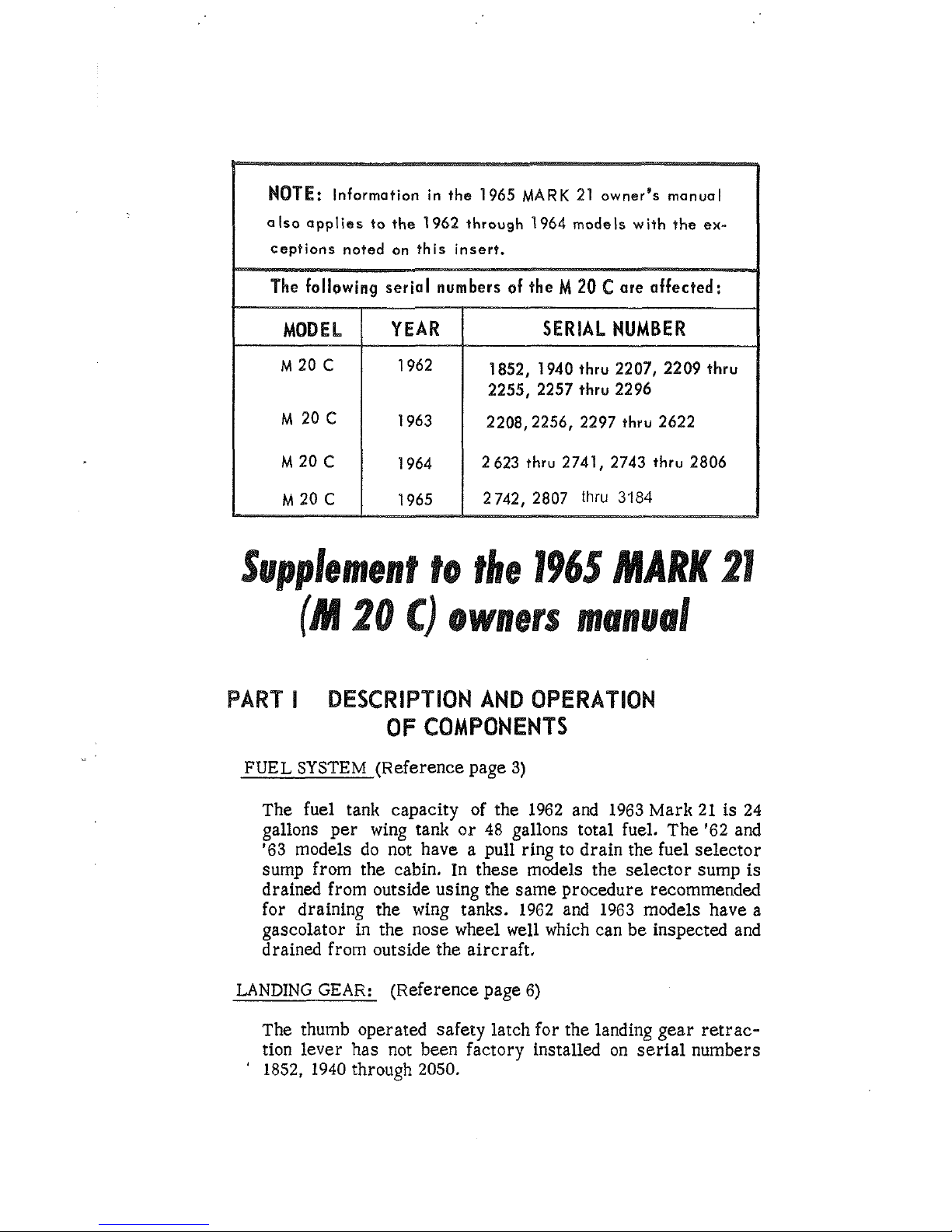
NOTE:
Information in the
1965
MARK
21
owner's manual
also applies
to
the
1962
through
1964
models with the
ex-
1852, 1940
thru
2207, 2209
thru
2255, 2257
thru
2296
2208,2256, 2297
thru
2622
ment
to
the
1965
MARK
21
owrrers
manual
PAR"1" DESCRIPTION AND OPERATION
OF COMPONENTS
FUEL
SYSTEM
(Reference page 3)
The fuel tank capacity of the 1962 and 1963 Mark 21 is 24
gallons per wing tank or 48 gallons total fuel. The '62 and
'63 models do not have a pull ring to drain the fuel selector
sump
from the cabin. In these models the selector sump is
drained from outside using the same procedure recommended
for draining the wing tanks. 1962 and 1963 models have a
gascolator in the nose wheel well which can be inspected and
drained from outside the aircraft.
LANDING
GEAR:
(Reference page 6)
The thumb operated safety latch for the landing gear retraction lever has not been factory installed on serial numbers
1852, 1940 through 2050.
POSITWE CONTROL SYSTEM: (Reference page 8)
The Positive Control section does not apply
to 1962, 1963
or 1964 models unless retrofit installation of the PC system
has been made.
TRIM SYSTEM: (Reference page 9)
The friction
adjsstment for the trim control wheel does not
apply to 1962 models.
FLAPS: (Reference page 9)
The 1962 and
I965 model fiaps are retracted by pulling the
release knob adjacent to the flap handle.
VACUUM
SYSTEM: (Reference page 10)
1962,
'63
and '64 models do not have a vacuum operated
cabin entry seep. These models have a manually operated
step retraction system
activated
by
a hand crank on the left
side panel near the pilot's knee. Turning
the crank clockwise
raises the step; counter
clockw
is,
lowers the step.
The vacuum regulator will maintain vacuum
between
3.5
and
5.0
inches of mercury on 1962, 1963 and 1964 models. The
vacuum warning lights for these airplanes are
see
accord-
ingly.
HEATING
AND VENTILATION SYSTEMS: (Reference pages 10
and 11)
1962 models do not have rear heat outlets. There
Ls
no left
side air scoop on 1962, 1963 or 1964 production aircraft.
Serial numbers 1852 and 1940 through 2693 do not have a
firewall-mounted radio cooling grill.
PART
II
FLIGHT
PROCEDURES
WEIGHT AND BALANCE: (Reference page 14)
1962 models are not equipped
with the utility shelf aft of the
main baggage compartment. Therefore, related weight limitation does not apply.
ENTERING THE AIRCRAFT: (Reference page
15)
Drain the fuel selector valve sump from outside the air-
craft on 1962 and 1963 models.
STARTING THE ENGINE:
(Reference page
15)
-
--
"Push to Stare" feature was installed on the ignition switch
beginning with 1963 models. On earlier aircraft, turning
the
ignition switch to "start" engages the starter and the
"shower of sparks" ignition.
COLD
WEATHER AND MANUAL STARTI* (Reference page 16
To manually start aircraft with serial numbers 1852 and 1940
through 2342 use
the
following procedures:
(1)
Turn off the "starter disconnect switch"
located on the
upper center section of the
firewall under the instrument
panel. The switch disconnects the starter so that only
the starter vibrator operates when the
magneto switch is
turned to the start position.
(2)
As the engine is "propped", hold the magneto switch in
the "start" position. This operates the starter vibrator
and furnishes retarded spark to the engine.
(3) When the engine starts, release the switch to the "both"
position and place the starter disconnect switch in the
"on" position.
Aircraft serial numbers
from 2343 may be manually started
as described on page
16.
PART
ill
SERVICE
AND
MAINTENANCE
VACUUM
STEP: (Reference page 27)
The maintenance check of the step retraction does not apply
to 1962, 1963 or 1964 models.
REQUIRED DATA
:
(Reference page
28)
The F.A .A. approved flight manual is part
of
the requird
data for
1962 and 1963 models. Placards in the aircraft and
data in the owner's manual supercede the flight manual data
for
later models.
PART
IV
PERFORMANCE
DATA
(Reference pages 29-37)
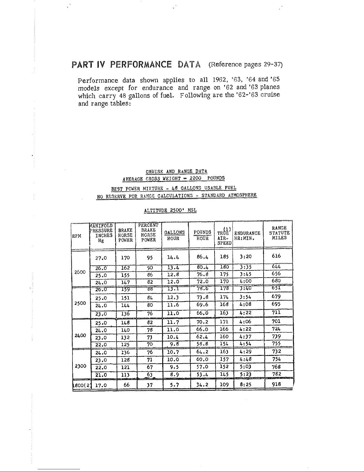
Perforrnance data shown applies to all 1962, '63, '64 and '65
models except for endurance and range on '62 and '63 planes
which carry
48
gallons of fuel. Following are
the
'62-'63 cruise
and range tables:
CRUISE
AND
RANGE DATA
AWRGGE
CROSS
WEIGHT
-
2200
POUNDS
BEST
POWER
MIXTURE
-
48
GALLONS USABLE FUEL
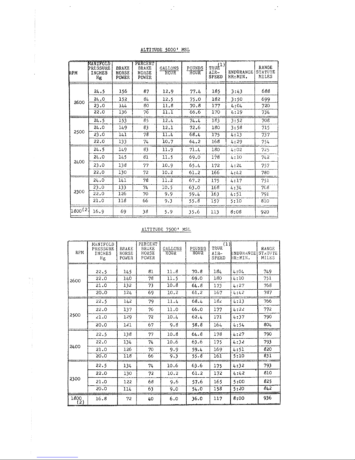
ALTITUDE
5000'
K3&
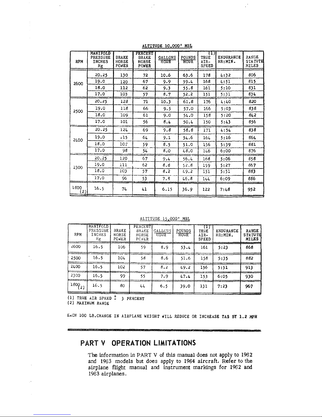
AETIPUDE
10,000'
MSL
I
I
I
I
I
I
J
(1)
TRUE AIR SPEED
?
3
PERCENT
(2)
MAXIMUM
RANGE
EACH
100
LB.CHANGE IN AIRPLANE WEIGHT
#ILL
REDUCE OR iNCREASE
TAS
BY
1.2
MPH
PART
V
OPERATION
LlMlTATlONS
The information in
PART
V
of this manual does not apply
to
1962
and
1963
models but does apply to
1964
aircraft. Refer to the
airplane flight manual and instrument markings for
1962
and
1963
airplanes.
OPERATE
THIS
AIRCRAFT
ONLY
-
@
after
reading
owners
manual
@
with
owners
manual
on
board
@
after
you
are
fully
qualified
81
understand
all
of
the
aircraft
operating
characteristics&
limitations
MARK
2
OWNERS
MANUAL
Thank you for choosing a hlooney
The wisdom of
your
selection of a Mooney Mark
21
will
be
proved many times as your hours in this exceptional
airplane increase.
It
takes a
long
time
and a lot
of
flying to appreciate
all of the
mauy outstanding features built into the
Mark
21.
This
owners manual
will
help you know
your
airplane
better and will make your experience with the Mark
21
more enjoyable.
Welcome
to
the rapidly growing family of blooney own-
ers.
M001VE
B8
AIRCRAFI,
INC.
LOUIS
SCHREINER
FIELD . XERRVILLE.
TEXAS
1965
MARK
21
PART
I
DESCRlPTlON
AND
OPERATBa
OF
COMPONENTS
Page
Genera
I
Propeller
Engine
Engine ignition
Fuel System
E
lectrical System
Airframe
Landing Gear
Flight Controls
Mooney Positive Control System
Trim System
Flaps
Vacuum System
Brakes
Heating and Ventilation Systems
Pictures

PART
!l
FLIGHT
PROCEDURES
General
Weight and Balance
Pre-F
light Inspection
Entering the Airplane
Starting the Engine
Cold Weather and Manual Starting
Taxiing
and Ground Operation
Pre Take-Off Check
Take-Off and
Climb
Power Changes
Cruise Procedures
Indicated Airspeed
Fuel Management
bet-Down Procedures
Carburetor
Heat
Landing Procedures
Normal Landing
Stopping
the
Engine
PART
III
SERVICE
AHD
MIHTEHANCE
Page
Genera
I
Ground Wondl ing
Propeller
Engine
Battery
Care of Interior
Care of Exterior
Windows
banding Gear
Vacuum Operated Step
Required Data
Service Letters and
Bulietins

PART
l\d
PERFORMANCEDATA
Take-Off and
Climb
Data
(Fig-
7)
Climb Performrsnee (Fig.
2)
Cruise and Range (Fig.
3)
(Fig.
3A)
(Fig,
3B)
(Fig.
3C)
(Fig.
3D)
Stall
Speed
vs.
Bonk Angle
(Fig.
4)
Maximum
Range & Glide Chart
(Fig.
5)
Landing
Dora
(Fig.
6)
PART V OPERAnING
LIMBPATBONS
Airspeed Limitations
Engine Operating
Limitations
Engine lnstrunnent Markings
Page
2
9
3
0
31
32
33
34
35
36
36
3
7
38
3
8
3
8
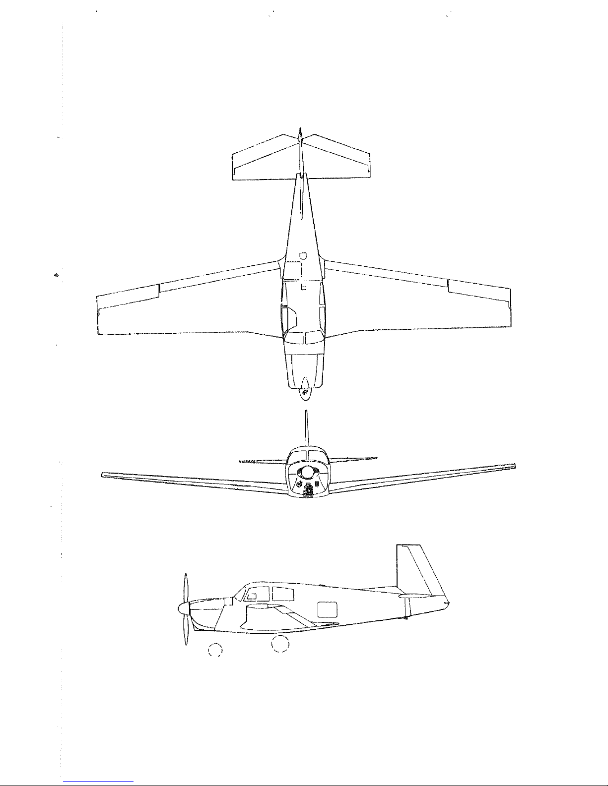
The Mark
21
is
a single engine four-place low wing, retractable
tricycle landing gear
airplane, The design and operation of this
aircraft are conventional with few exceptions, There are no
tricky or complex operational characteristics requiring unusual
or extreme piloting skill. This section
will describe some of
the components of the Mark
2%
and operating details.
PROPELLER
The Mark
2%.
uses an aluminum alloy constant sped propeller
of
74
inch diameter. The pitch of the blades is contro%ld
by
engine oil pressure which acts
to
increase or decrease blade
angle of attack and thereby control engine sped. The propeller
control in the cabin operates
the
propdler governor which
contro%s the oil pressure providd to the propeller hub. The
governor
sating functions to maintain the engine at a constant
SF&
by actuating blade angle of ;track. In essence then, the
function of the
propeller control in the cabin
is
to regulate and
maintain the rotational
sped of the engine
at
a desired setting,
The Mark
21
is powered by the Lycoming 180hp 0-360-AID
four cylinder engine. This engine uses
91/98
octane fuel. Four
rubber bushings on the aft side of the engine provide mounting
and vibration isolation. Engine manifold pressure is regulated
5y
the push-pull throttle control on the panel.
The fuel-to-air ratio (mixture) is regulated by the hexagon
shaped push-pull control located between the throttle and propeller controls in the cabin. The Mark
21
engine baffling directs
air flow over the cylinders for cooling in flight. Cowl flaps are
provided on .the lower cowling to allow more free air flow on
the ground and during low speed, high power conditions
(Leo,
climb conditions). Cowl flaps should always be open on the
ground, and prolonged engine operation on
the
ground should be
avoided to prevent engine overhearing.
A
push-pull control is
provided klow the instrument panel and to the right of the
pilot for
operation of the cowl flap.
The engine has a pressure-type wee-sump %ubsicaeion
syseern.
It has an eight quart capacity; however, as a general rule, when
the oil
level drops below six quarts, one quart
is
added. This
will maintain the oil level
between the
six
and seven wart
level.
See Pare
IPI
for tgrge of oil used and time kerween
oil
changes.
An
oil temperature thermostat, see for
180
I?*
is
located in
the oil reservoir to assure warm oil for ,311 operations. An oil
cooler
is
mounted on the lower %eft side of the cowling to pre-
vent the
oil from overheating. An oil filter mounted on the fise-
wall is available
as
optional ewipmene.
The Mark
29
ignition system
has
the following features:
1.
Two Bendix magnetos, the left mapeto being eqippd with
a
see
of retard breaker points.
2.
A
starting vibrator, located on the upper firewall, which
furnishes a shower of sparks for starting.
3.
A
switch which combines both ignition and starting functions.
4.
Shielded spark plugs and ignition harness to suppress radio
noises.
When the push-type starter switch
is
activated in the -'startD'
position, the starter vibrator sends an interrupted current
through the retard-breaker points while the right
magndo is
grounded out. The left magneto then provides a shower of sparks
to each cylinder after the piston has reached top dead center on
the compression stroke. The engine starts sooner and easier
because of this system,
FUEL
b"BSfEDIL
Fuel
is
comain4 in two imegral sealed sections in the front
part
of each wing root. Each tank will hold
26
gallons of gasoline.
These fuel tanks each have a sump drain under the wing from
which
fuel may be sampld to check for water or sediment con-
tamination. A small plastic cup with an actuator prong
is
pro-
vided to obtain
fuel samples. If water
is
present in the fuel, a
distinct line separating the water from the gasoline may be
seen through the plastic cup. Water,
king heavier, will be on
the bottom of the
cup, ad the light-colored fuel will
be
on
top.
Aluminum fuel lines feed the fidd from the tank to a two-way,
positive-setting selector valve on the
floor ahead
0%
the pilot's
seat.
The selector valve feeds fuel from one of the tanks at a
time, and
also has an "off" position for extended periods of
storage o
I-
for emergency use. The selector valve also contains
a
sump
drain which
is
actuatd by pullfrag the ring adjacent
to
the fuel valve handle, Switch the selector valve handle to the
right and left
tanks
to drain the respective %laaes.
Be
sure sump
drain returns
to
normal closed position after releasing the ring.
Fuel
is
fed from the selector valve through the electric boost
pump,
then
to
the engine driven punip and into
the
carburetor.
The electric boost pump
is
turned on for take-off and Lnding
to provide fuel pressure if the engine driven pump malfunctions.
WARNING: Under no circumsfances should aviation fuel of
a
lower grade than 91/98 octane be used. Aviation
fuels may
distinguished by their color: 80 octane
is
red, 91 octane is blue, and 100 octane
is
green. If
91/98 octane is not available,
100/130 octane gas-
oline may be used.
THE ELECTRICAL
SYS"6M
The
Mark
21
electrical system
is
provided with a 50 amp
12
volt generator and a 35 amp-hour battery which
is
located
on
the forward left side of the firewall. All electrical systems can
 Loading...