

Mooney Ranger M20C 1968 Owner's Manual

--
OWNERS
MANUAL
OPERATE THIS AIRCRAFT
ONLY
-
after reading
owners manual-
@
with owners manual on board
@
after you are fully qualified
&
understand
all of
the aircraft operating characteristics& limitations
OWNERS
MANUAL
SERIAL
NUMBERS
680001
&
ON
Neither
this
document (nor any amendment
hereto)
nor anything contained herein shall be constrild as
an
assilmptisn by Mooney Aircraft Corprat on
+a
Pennsylvania corporation, of any of the
obligations
or liabilities
of
its predecessors. Mooney
Aircraft.
Inc.
or
Moaney Corporation, both Texas corporations, or
as
otherwise imposing on Mooney
Aircraft
Corporation
my
of the obligations
or
liabilities
of
its
predecessor@,
NOVEMBER
1967
ISSUE
MBONEY
A
IRCRAFT,
INC.
KERRVI 6 LE, TEXAS
78028
MANUAL NUMBER 68-20C-OM-B
LIST
OF
REVISED
PAGES
ISSUED
PlNSERT LATEST REVISED PAGES
--
DESTROY SUPEWEDED PAGES.
PAGE
DATE
OF
PAGE DATE
OF
NUMBER LATEST WEVlSlORl NUMBER LATEST
REVlSBON
*THE
ASTERISK INDICATES PAGES REVISED, ADDED, OR
DE-
LETED BY THE CURRENT REVISION.
ADDITIONAL COPIES OR CURRENT REVISIONS OF THIS PUBLICATION
MAY BE PURCHASED FROM YOUR LOCAL MOONEY DISTRIBUTOR
OR
DEALER.
7dIt
a&
GENEME DESCRIPTION
..
:
.......
SECTION
SYSTEMS OPERATIONS
...........
SECTION
NORWL PROCEDURES
...........
SECTION
........
EMERGENCY PROCEDURES SECTI[BN
%mP%ATIONS
..................
SECTION
PERPBRWNCE
................
SECTION
SERVICIONG.
...................
SECTION
This manual
is
issued as your operating guide for the
Moomy Ranger. It is important that you--regardless of
your previous experience--carefully read the handbook
from cover to cover and review it frequently.
IMPORTANT: THIS MANUAL CONTAINS Federal
Aviation Agency-Delegation Option Authority APPROVED LIMITATIONS AND MUST BE CARRIED
IN
THE AIRCRAFT
AT
ALL TIMES.
All information and illustrations in this manual are based
on the latest product information available at the time of
publication approval. The right
is
reserved to make changes
at any time without notice. Every effort has been made to
present the material in a clear and convenient manner to
enable you to use the manual as a ready reference. Your
cooperation in reporting presentation and content recom-
mendations
is
solicited.
eO@BeeBseeeBe@t3
Company warrants each new airplane manufactured by it to
be free from defects in material and workmanship under
normal use and service, provided, however, that this warranty
is
limited to making good at Company's factory any
part or parts thereof which shall within
12
months from
date of original airworthiness certificate be returned to
Company with transportation charges prepaid, and which
upon Company's examination shall disclose to Company's
satisfaction to have been thus defective; this warranty being expressly in lieu of all other warranties expressed
or
implied, and all other obligations or liabilities on the part
of Company, and Company neither assumes or authorizes
any other person to assume for it any other liability in connection with the sale of its airplanes. This warranty shall
not apply to any airplane whichshall have been repaired or
altered outside of Company's factory,
whichin the judgment
of Company affects the airplane's stability or reliability,
norwhich in the opinion of the Company has been subject to
misuse, negligence, or accident. Equipment and accessories not manufactured by seller are guaranteed only to
the extent of the original manufacturer's guarantee.
SECTION
I.
GENERAL
DESCRIPTION
DESBGN
FEATURES
..........................
AIRFRAME. 1-2
........................
POWERPLANT
1-2
FLIGHTCONTROLS
....................
-1-3
LANDING GEAR
.......................
I-
3
SPECIFICATIONS
OUTLINE
POWERPLANT
........................
1-3
...................
PRQPELLER
00smes1-4
MNDmGGEAR
.......................
1-4
..........................
FUEL&OIL 1-5
WEIGHT
&
ILOADmG
....................
1.5
...............
BAGGAGECOMPARTMENT 1.5
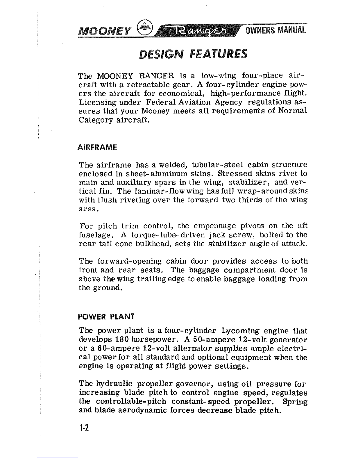
DESIGN
FEATURES
The
MOONEY
BANGER
is
a low-wing four-place air-
craft with
a
retractable gear. A four-cylinder engine pow-
ers the aircraft for economical,
high-performance flight.
Licensing under Federal Aviation Agency regulations
as-
sures that your Mooney meets all requirements of Normal
Category aircraft.
AIRFRAME
The airframe has a welded, tubular-steel cabin structure
enclosed in sheet-aluminum skins. Stressed skins rivet to
main and auxiliary spars in the wing, stabilizer, and vertical fin. The laminar- flow wing has full wrap- around skins
with flush riveting
over the forward two thirds of the wing
area.
For pitch trim control, the empennage pivots on the aft
fuselage.
A
torque-tube- driven jack screw, bolted to the
rear tail cone
bulkhead, sets the stabilizer angleof attack.
The forward-opening cabin door provides
access to both
front and rear seats. The baggage compartment door
is
above the wing trailing edge to enable baggage loading from
the ground.
POWER PLANT
The power plant
is
a four-cylinder Lycoming engine that
develops
180
horsepower.
A
50-ampere 12-volt generator
or a
6bampere 12-volt alternator supplies ample electrical power for all standard and optional equipment when the
engine
is
operating
at
flight power settings.
The hydraulic propeller governor, using oil pressure for
increasing blade pitch to control engine speed, regulates
the controllable-pitch constant- speed propeller. Spring
and blade aerodynamic forces decrease blade pitch.
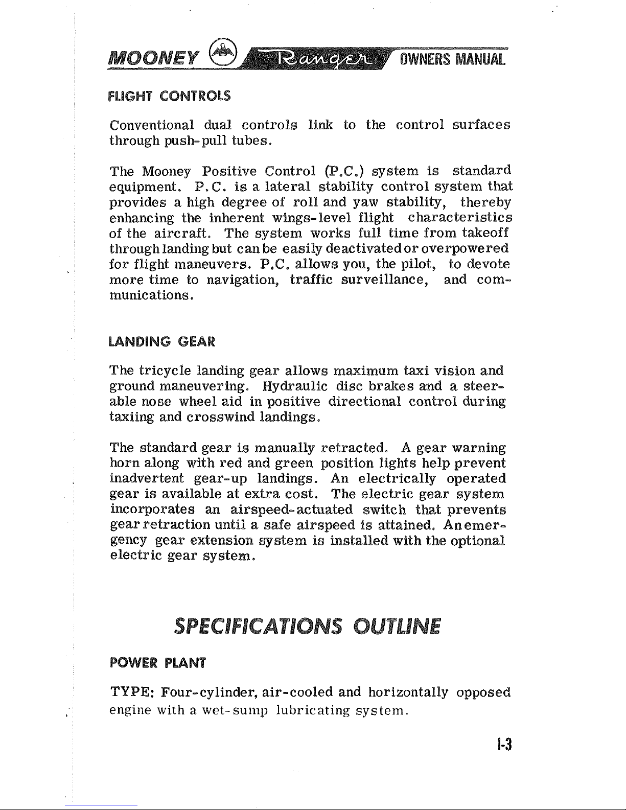
FLIGHT CONTROLS
Conventional dual controls link to the control surfaces
through push-pull tubes.
The Mooney Positive Control
(P.C.)
system
is
standard
equipment,
P,
C.
is
a lateral stability control system that
provides a high degree of roll and yaw stability, thereby
enhancing the inherent wings- level flight charac
teristics
of the aircraft. The system works full time from takeoff
through
lmding but can be easily deactivated or overwwered
for flight maneuvers. P,C. allows you, the pilot,
to devote
more time to navigation, traffic surveillance, and communications,
The tricycle landing gear allows maximum taxi vision and
ground maneuvering.
Hy&aulic disc brakes ad a steer-
able nose wheel aid in positive directional control during
taxiing and crosswind
landings.
The standard gear
is
manually retracted.
A
gear warning
horn along with red
and green position lights help prevent
inadvertent gear-up landings. An electrically operated
gear
is
available at extra cost.
The electric gear system
incoqorates
an
airspeed-achated switch
that
prevents
gear retraction until
a
safe airspeed
is
aeained, Amemer-
gency gear e~ension system
is
installed with the optional
electric gear
system*
SPECIFICATlONS
OUTLINE
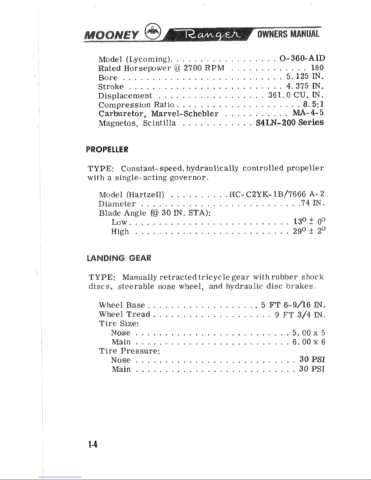
POWER
PUNT
TYPE: Four-cylinder, air-cooled and horizontally opposed
engine
with a wet-sump lubricating system.
.................
Model (I.jyconling).
0-
360-AID
.............
Rated Horsepower @ 2700 RPM
180
...........................
Bore 5.125
IN.
..........................
Stroke
4.375
IN.
..................
Displacement 361.0
CU.
TN.
.....................
Con~pression Ratio
8.5:
1
Carburetor, Marvel- Schebler
...........
MA-
4-
5
............
Magnetos, Scintilla
S4W-
2OQ
Series
PROPELLER
TYPE: Constant- speed, hydraulically controlled propeller
with a single-acting governor.
..........
Model (Hartzell)
HC- C2YK- 1B/7666
A-
2
Diameter
..........................
.74
IN.
Blade Angle
(@
30
IN.
STA):
..........................
Low.
P3O
2
oO
..........................
High 29O
+
2'
LANDlNG
GEAR
TYPE: Manually retracted tricycle gear with rubber shock
discs, steerable nose wheel, and hydraulic disc
brakes.
Wheel Base ...................
5
FT
6-9/16
IN.
Wheel Tread ....................
9
FT
314
IN.
Tire
Size:
Nose
..........................
5.00
x
5
Main
..........................
6.00
x
6
Tire Pressure:
...........................
Nose
30
PSI:
Main
...........................
30
PSI
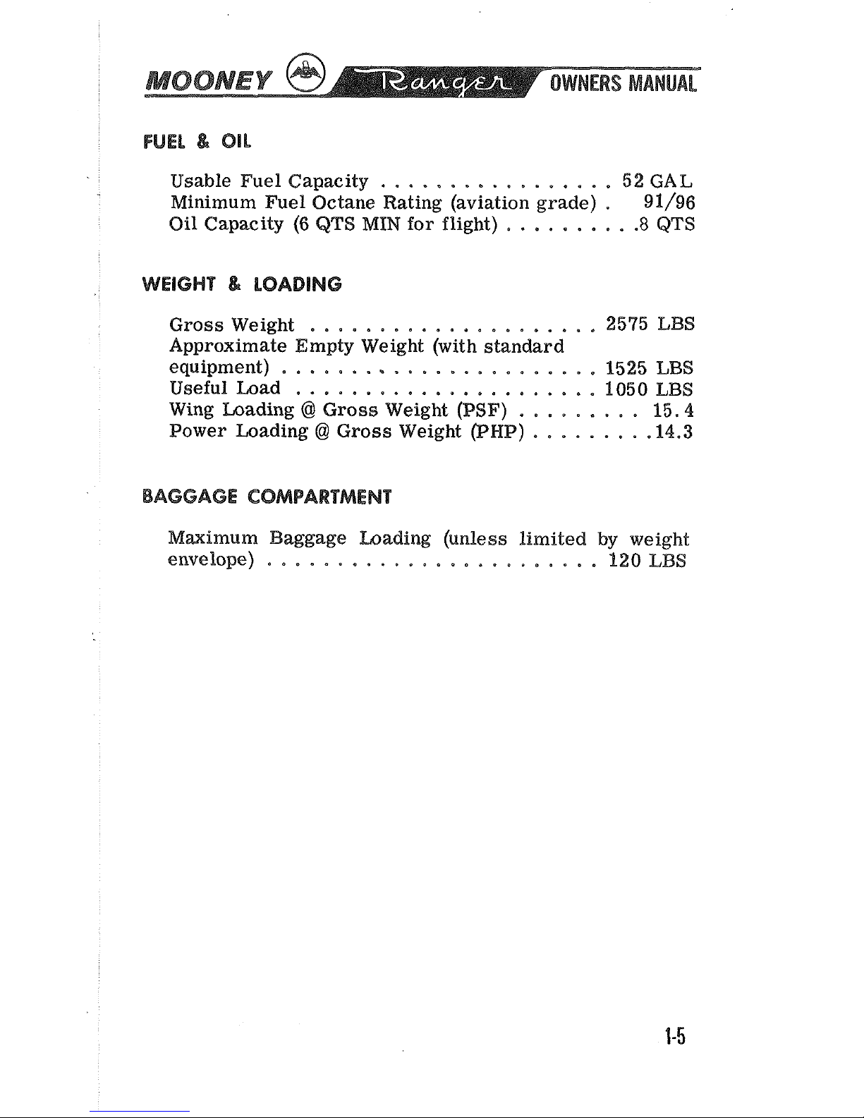
Usable Fuel Capacity
.................
5%
GAL
Minimum Fuel Octane Rating (aviation grade)
.
91/96
Oil Capacity
(6
QTS
MIN
for flight)
.........
.8
QTS
Gross Weight
.....................
2575
IAN
Approximate Empty Weight (with standard
equipment)
.......................
1525
LBS
Useful Load
......................
1050 LBS
Wing Loading
@
Gross Weight
(PSF)
.........
15.4
Power Loading @ Gross Weight (PNP)
........
-14.3
BAGGAGE
COMPARTMENT
Mzimum Baggage bading (unless limited by weight
envelope)
........................
120
LBS
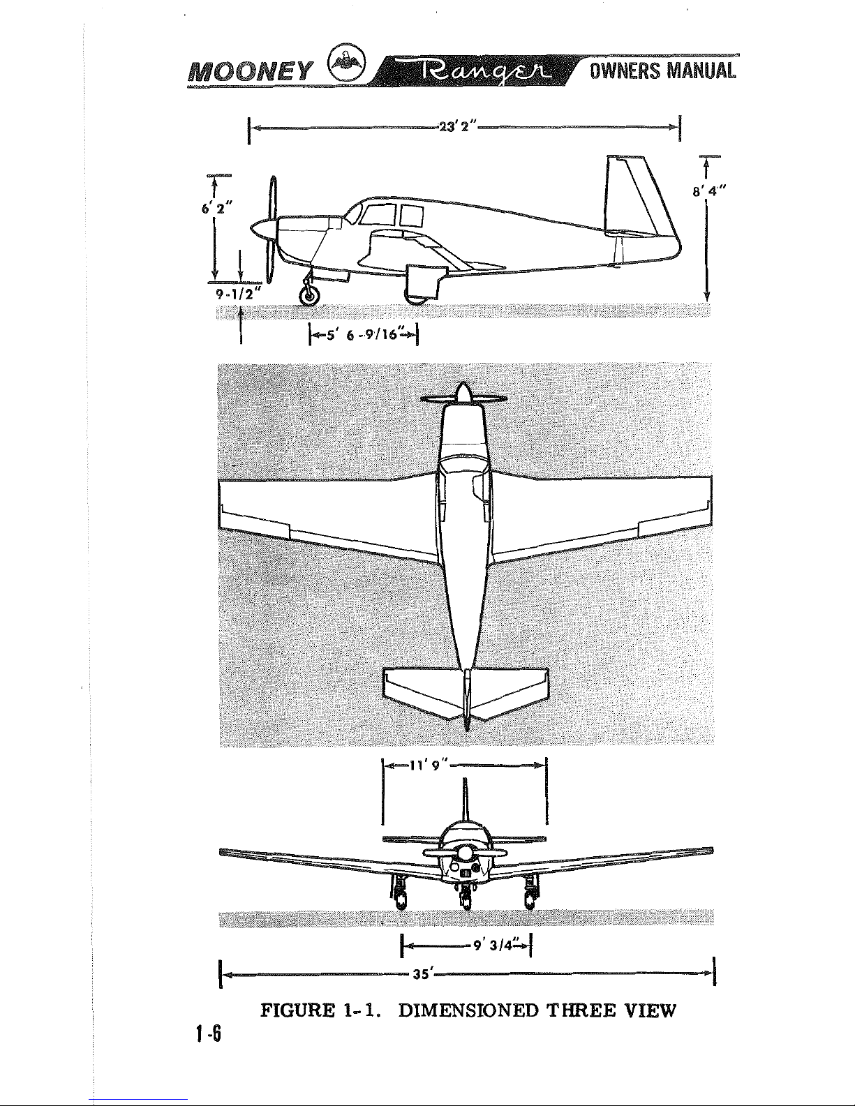
FIGURE
1-
1.
DIMENSIONED THREE VIEW
1
-6
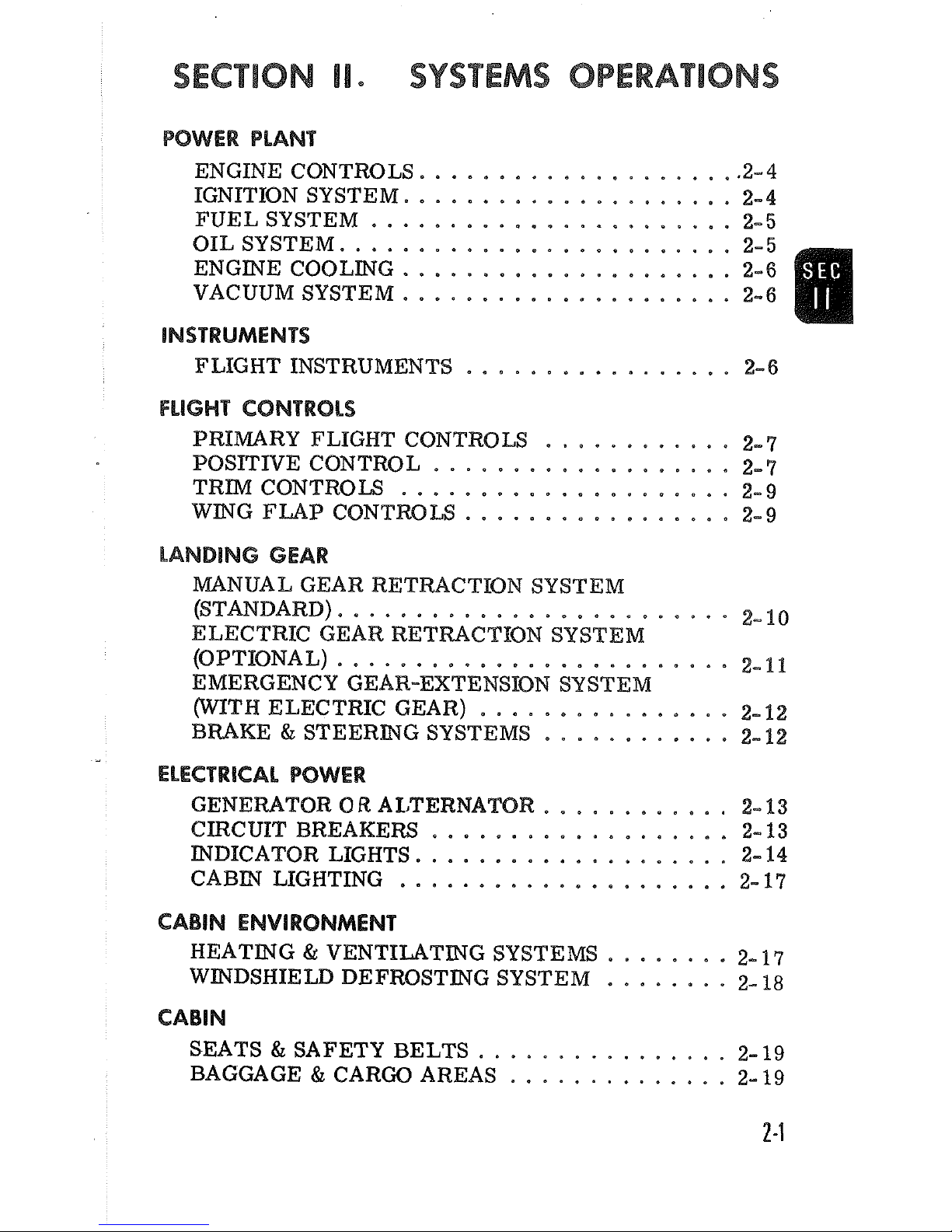
SECTION
SYSTEMS
OPERATIONS
POWER PLANT
....................
ENGINE CONTROLS
-2-4
IGNITION SYSTEM
.....................
2-4
.......................
FUELSYSTEM
2-5
-
OILSYSTEM
.........................
2-5
ENGINE COOLING
.....................
2-6
VACUUMSYSTEM
.....................
2-6
INSTRUMENTS
FLIGHT INSTRUMENTS
.................
2-6
FLlGHP CONTROLS
PRImRY FLIGHT CONTROLS
............
2-7
POSITIVE CONTROL
...................
2-7
TRIM CONTROLS
.....................
2-9
WING
IFUP
GONT128W
.................
2-9
LANDlNG
GEAR
MANUAL GEAR RETMCTICON SYSTEM
.........................
(STANDARD) 2-10
ELECTRIC GEAR
RETMCTION SYSTEM
(OPTIONAL)
.........................
2-11
EMERGENCY GEAR-EXTENSION SYSTEM
(WITH ELECTRIC
GEAR)
................
2-12
BMKE & STEERING SYSTEMS
............
2-12
ELECTRICAL POWER
GENERATOR
O
R
AIjTERMIATOR
............
2-13
CIRCUIT BREAKERS
...................
2-13
INDICATOR LIGHTS
....................
2-14
CABINLIGHTING
.....................
2-17
CABIN ENVIRONMENT
HEATING & VENTILATBNG SYSTEMS
........
2-17
WmDSHIELD DEFROSTING SYSTEM
........
2-18
CABIN
SEATS & SAFETY BELTS
................
2-19
BAGGAGE
&
CARGO AREAS
..............
2- 19
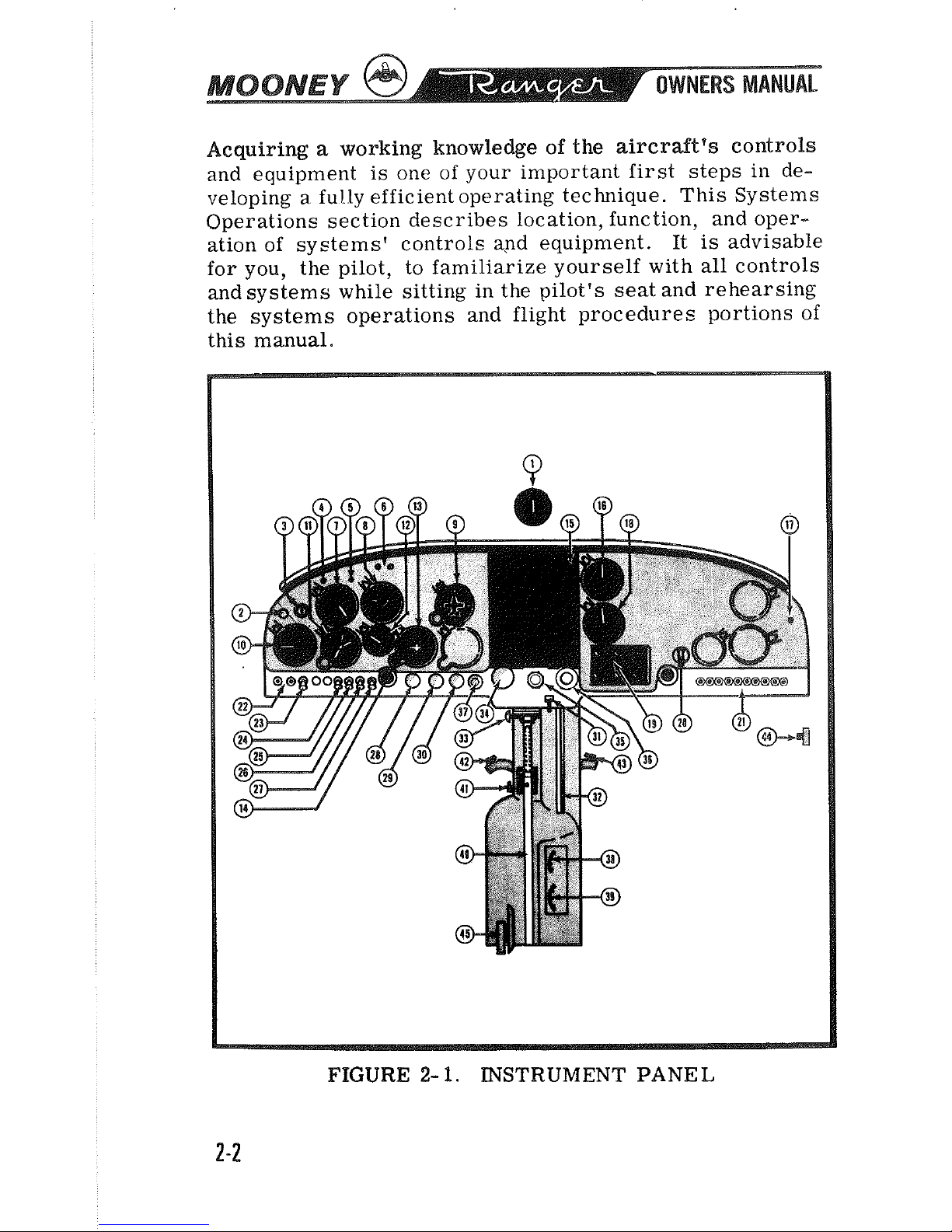
Acquiring a working knowledge
of
the aircraft's controls
and equipment is one of your important first steps in developing
a
fully efficient operating technique. This Systems
Operations section describes location, function, and oper-
ation of systems' controls
and
equipment. It
is
advisable
for you, the pilot, to familiarize yourself with all controls
and systems while sitting in the pilot's seat and rehearsing
the systems operations and flight procedures portions of
this manual.
FIGURE
2-
1.
INSTRUMENT
PANEL
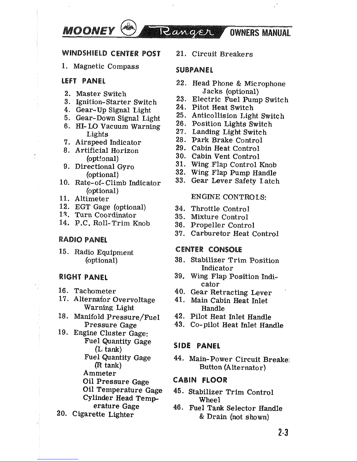
WINDSHIELD CENTER POST
1.
Magnetic Compass
LEFT
PANEL
2. Master Switch
3. Ignition-Starter Switch
4. Gear-Up Signal Light
5. Gear-Down Signal Light
6.
HELO Vacuum Warning
Lights
9.
Airspeed Indicator
8.
Artificial Horizon
(optional)
9. Directional Gyro
(optional)
10. Rate-of- Climb Indicator
(optional)
11.
Altimeter
12. EGT Gage (optional)
13, Turn Coordinator
14,
P.C. Roll-Trim Knob
RADIO
PANEL
15. Radio Equipment
(optional)
RIGHT
PANEL
16. Tachometer
17. Alternator Overvoltage
Warning Light
18. Manifold
Pressure/Fuel
Pressure Gage
19. Engine Cluster Gage:
Fuel Quantity Gage
(L
tank)
Fuel Quantity Gage
@
tank)
Ammeter
Oil Pressure Gage
Oil Temperature Gage
Cylinder Head Temp-
erature Gage
20.
Cigarette Lighter
21. Circuit Breakers
22.
Head Phone & Microphone
Jacks (optional)
23. Electric Fuel Pump Switch
24.
Pitot Heat Switch
25. Anticollision
Light Switch
26. Position Eights Switch
27.
L,anding Light Switch
28. Park Brake Control
29.
Cabin Neat Control
30. Cabin Vent Control
31. Wing Flap Control Knob
32. Wing Flap Pump Handle
33. Gear Lever Safety
Latch
ENGINE CONTrn%.S:
34. Throttle Control
35. Mixture Control
36.
Propeller Control
37. Carburetor Heat Control
d
ENTER
CONSOLE
38. Stabilizer Trim Position
Indicator
39.
Wing Flap Position Pndi-
cator
40. Gear Retracting Lever
41. Main Cabin Heat Inlet
Handle
42. Pilot Heat Inlet Handle
43. Co-pilot Heat Inlet Handle
SIDE PANEL
44. Main-Power Circuit Breake:
Button (Alternator)
CABIN
FLOOR
45. Stabilizer Trim Control
Wheel
46. Fuel Tank Selector Handle
&
Drain (not shown)
PLANT
The throttle, mixture, and propeller controls are centrally
located on the instrument panel; the push-pull throttle control regulates manifold pressure.
The push-pull mixture control between the throttle and
propeller control regulates the engine fuel-air ratio. The
propeller control regulates the propeller governor which
in turn controls engine RPM. Pushing the propeller control forward increases RBM (low pitch), and pulling the
control aft decreases RPM (high pitch). Fine pitch changes
are made
by
turning the vernier knob counterclockwise to
decrease
RPM and clockwise to increase RPM.
All engine instruments are functionally grouped in the right
instrument panel. Color arcs on instrument faces mark
operating ranges. Proper interpretation of engine instrument readings is essential for selecting optimum control
settings and for
maintairaing mmimum cruise fuel economy.
Engine limitations are given in Section
V.
IGNITION
SYSTEM
The left magneto has a set of fixed-retard breaker points
that aid in smoother, easier starting.
A
battery-powered
starting vibrator supplies a long- duration boosted spark.
The starter-ignition switch, mounted on the left of the in-
strument panel, combines both ignition and starting functions. Turning the ignition key clockwise through
R,
L,
and BOTH to the START position and then pushing forward
on the key and receptacle engages the starter. Releasing
the key when the engine starts allows the switch to return
by spring action to the
BOTH
position. For safety, the
starter-ignition switch must be left
at
OFFwhen the engine
is
not running.
FUEL
SYSTEM
Two integral sealed sections carry the fuel in the forward
inboard area of the wings. Full fuel capacity
is
52
gallons.
There are sump drains at the lowest point in each tank for
taking fuel samples to check for sediment contamination and
condensed water accumulation. Section
VII
discusses the
fuel sampling procedure.
An illuminated three-position fuel selector handle on the
cabinfloor sets the selector valve below the floorboard for
LEFT tank,
RIGHT
tank, or the OFF position. The fuel
selector valve assembly contains a valve for draining
condensedwater and sediment from the lowest point in the fuel
lines before the first flight of the day and after each refueling. Section
VII
discusses the selector valve flushing pro-
cedure.
F~el feeds from one tank at a time through the selector
valve and the electric fuel pump
enroute to the engine- driven
pump and the carburetor. Electric fuel-level transmitters
in the
tanks operate fuel gages in the engine cluster, The
master switch actuates the fuel quantity indicator system
to maintain an indication of fuel
remalnhg in each tank.
The fuel pressure
gage registers line pressure delivered
to the carburetor. Vents in each fuel tank allow for overflow and ventilation,
Olb
SYSTEM
The engine has a full-pressure wet-sump oil system with
an 8-quart capacity. The automatic bypass control valve
routes oil
flow around the oil cooler when operating tem-
peratures are below normal or when the cooling radiator
is
blocked.
The engine oil should be kept at
6
to 8 quarts.
Lycoming
Service Instruction
1014
(latest revision) gives recom-
mended oil spec if'ications and oil change intervals.
The down-draft engine coollng system provides ground and
inflight power plant cooling. Engine baffling directs air over
and
around the cylinders and out the cowl flap openings.
VACUUM
S"SSPEM
An engine- driven vacuum pump supplies suction for the optional gyroscopic flight instruments and the Mooney Positive Control system. Air entering the vacuum-powered
instruments
is
filtered; hence, sluggish or erratic
opera-
tion of vacuum-driven instruments may indicate that
a
clogged vacuum filter element
is
preventing adequate air
intake. The
HI
or
LO
indicator light will glow
if
vacuum
is
above or below limits.
INSTRUMENTS
FLIGHT
INSTRUMENTS
All primary flight instruments are grouped on the floating
shock-mounted flight panel directly in front of the pilot's
seat. Standard flight instrumentation includes the airspeed
indicator, the altimeter, and the turn coordinator. The optional flight instruments are the artificial horizon, the
direction gyro, and the vertical speed indicator. The flapposition indicator
is
in the center console below the instru-
ment panel.
An optional eight-day clock can be mounted in the pilot's
control wheel. The magnetic compass
is
mounted on the
windshield post above the instrument panel. The outside
air temperature gage with probe is installed through the
winds hie ld.

A
pitot tube, mounted on the lower surface of the left wing,
picks up airspeed indicator ram air. An optional heated
pitot prevents pitot tube icing. Static ports on each side
of the tail cone supply static airpressure for the altimeter
and the airspeed indicator. An optional alternate static
pressure source valve may be installed.
A
stall warning horn, triggered by a sensing vane on the
left wing leading edge, will sound when airspeed drops to
near stall speed. Landing gear position lights on the panel
will show red when the gear
is
retracted, Reducing power
below
10
inches manifold pressure when the gear
is
not in
the down- and- locked position will cause the gear warning
horn to sound.
FLIGHT
CONTROLS
PR%MARPI
FLIGHT
CONTROLS
Push-pull tubes withself-aligning rodend bearings actuate
the primary flight eo~tsol surfaces.
Beveled aileron
trailing edges help reduce pilot control forces requiredfor flight
maneuvering. A spring- loaded interconnect device indirectly joins the aileron and rudder control systems to assist in
lateral
aund
directional stability during flight maneuvers.
Control surface gap strips
minimize airflow sooilage at the
hinge
sbts and reduce drag. The co-pilot's rudder pedals
are removable.
POSITIVE
CONTROL
The Mooney Positive Control
(B.C.)
system provides a high
degree of roll and yaw stability, thereby enhancing the inherent wings- level flight characteristics of the aircraft.
Positive Control will hold an average heading over a long
periodof time when the aircraft
is
trimmed properly. However, without the installation of a magnetic heading lock,
P.C. will not maintain an absolute preselected heading.
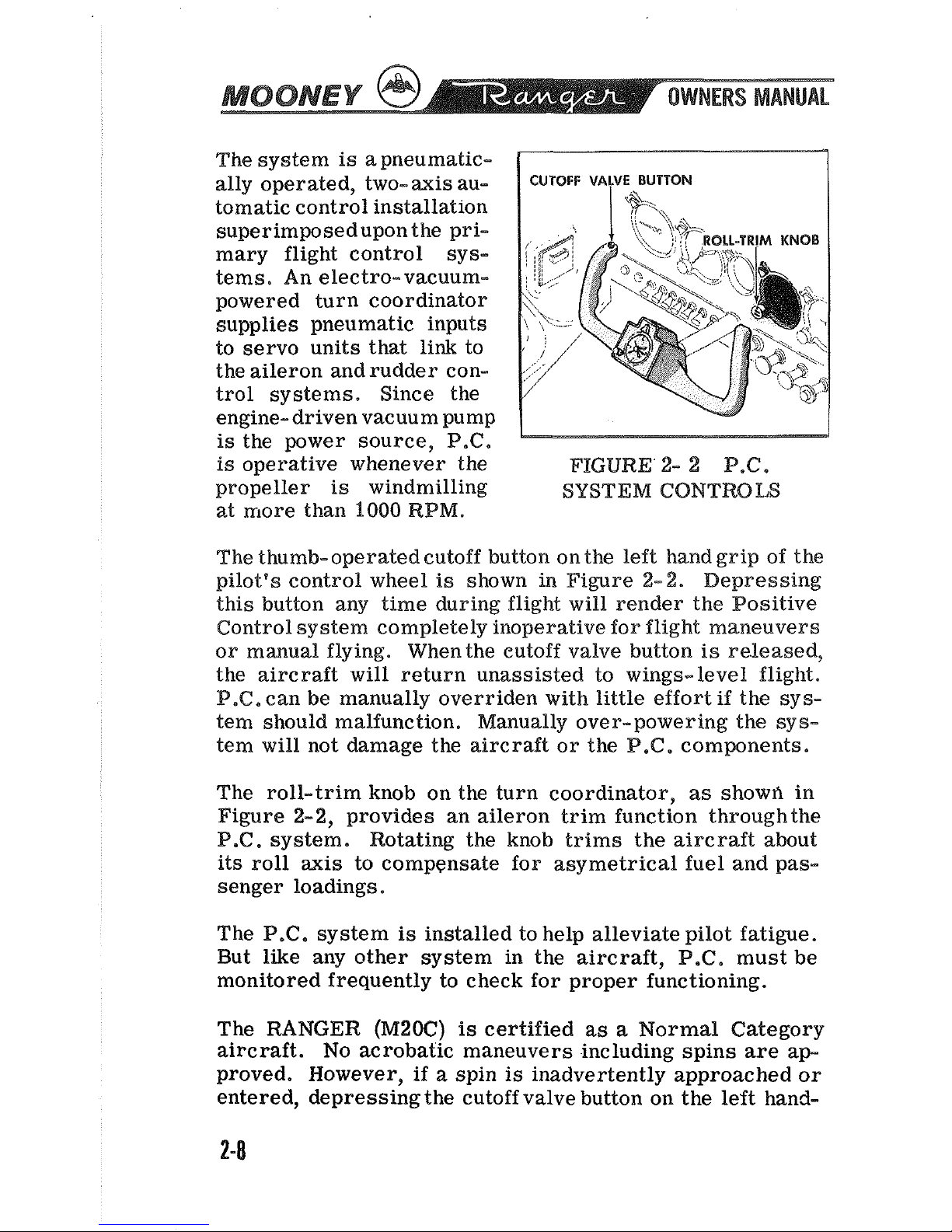
The system
is
a
pneumatic-
ally operated, two- axis au-
tomatic control installation
superimposedupon the primary flight control systems. An electro-vacuumpowered turn coordinator
supplies pneumatic inputs
to servo units that link to
the aileron and rudder control systems. Since the
engine- driven vacuum pump
is
the power source,
B.C.
is
operative whenever the
FIGURE' 2-
2
P.C.
propeller
is
windmilling
SYSTEM
CONTNLS
at more than
1000
RPM.
CUTOFF
VALVE
BUTTON
The
thumb-operated cutoff button on the left hand grip of the
pilot's control wheel
is
shown in Figure
2-2.
Depressing
this button any time during flight will render the Positive
Control system completely inoperative for flight maneuvers
or manual flying. When the
eutoff valve button is re.leased,
the aircraft will return unassisted to wings-level flight.
P.C.
can be manually overriden with little effort
if
the sys-
tem should malfunction. Manually over- powering the sy
s-
tem will not damage the aircraft or the
Be@.
components.
The roll-trim knob on the turn coordinator,
as
showrl in
Figure 2-2, provides an aileron trim function through the
P.C.
system. Rotating the knob trims the aircraft about
its roll axis to compensate for asymetrical fuel and passenger loadings.
The
P.C.
system
is
installed to help alleviate pilot fatigue.
But like any other system in the aircraft,
P.C.
must be
monitored frequently to check for proper functioning.
The RANGER
(M20C)
is
certified as a Normal Category
aircraft. No acrobatic maneuvers including spins are approved. However, if a spin is inadvertently approached or
entered, depressing the cutoff valve button on the left hand-
grip of the pilot's control wheel will de-energize the
P.C.
system while using normal spin recovery techniques. Spin
recovery can be executed from the
co- pilot's side
by
over-
powering the
P.G.
system.
TRIM CONTROLS
For pitch trim control, the entire empennage pivots on the
tail cone
attachmentpoints to increase or decrease the hori-
zontal stabilizer angle of attack. This design allows flight
trim establishment with minimum control surface deflection.
A
pointer in a slot located in the center console below the
instrument panel indicates stabilizer trim position. Forward rotation of the trim wheel lowers the nose; rearward
rotation raises the nose in flight.
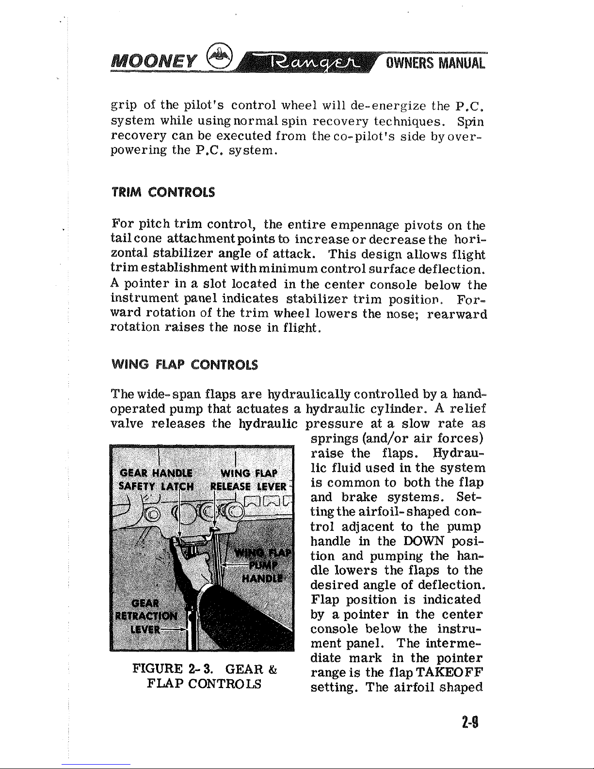
WING
FMP
CONTROLS
The wide- span flaps are hydraulically controlled
by
a
hand-
operated pump that actuates
a
hydraulic cylinder. A relief
valve releases the hydraulic pressure
at
a
slow rate
as
FIGURE
2-
3.
GEAR
&
FLAP
CONTROLS
springs (and/or air forces)
raise the flaps. Hydraulic fluid used in the system
is
common to both the flap
and brake systems. Set-
ting the
airfoil- shaped con-
trol adjacent to the pump
handle in the
DOWN
position and pumping the handle lowers the flaps to the
desired angle of deflection.
Flap
position
is
indicated
by
a
pointer in the center
console below the instrument panel. The intermediate mark in the pointer
range
is
the flap
TAKEOFF
setting. The airfoil shaped
control
is
placed in the
UP
position to retract the flaps.
To stop the flaps at
an
intermediate setting during retrac-
tion, the flap- shaped control
is
simply placed in the
DOW
position,
A
horn emitting a steady tone (different from the lower
pitch, intermittent tone of the gear-warning horn) warns
of approaching
stall,
Both warning horns are inoperative
when the master switch
is
off.
LANDlNG
GEAR
MANUAL
GEAR
RETRACTION
SYSTEM
(STANDARD)
The standard tricycle landing gear
is
unique in that it
is
manually retracted.
The system operates by direct mec-
hanical linkage. Manual retraction of the gear
is
aided by
bungee-type springs in the fuselage and assist springs in
the wing
thatbalance the weight of the gear. Rubber shock
discs in the welded tubular
steel gear structure absorb the
shock of landing and rough terrain taxiing, Red and
green
lights on the instrument panel indicate gear position, Press-
ing forward the indicator lens housing test- illuminates
the
lights.
Depressing the safety latch button, sliding the gear handle
from the down socket, and moving the lever rapidly to the
floor between the seats retracts the gear. Sliding the handle
into the
uplock socket completes the operation.
The more
rapid the movement of thelever, the easier
it
is
to retract
the gear. The gear will retract easiest
at
low airspeeds.
Sliding the gear handle from the
uplock socket and moving
the lever forward to the instrument panel lowers the gear.
Sliding the handle into the
downlock socket and checking
the green indicator light and safety latch for
a
down-and-
locked indication completes the gear lowering operation.
There are three ways to see that the manually retracted
gear is down- and- locked:
(1)
The gear- down indicator light illuminates.
(2)
The safety latch on the retraction lever handle socket
is
engaged.
(3) The gear warning horndoes not sound at approach pow-
er settings of below
10
inches manifold pressure.
.
The red indicator light (marked GEAR-mEOCK)
is
on
when the handle on the retraction lever
is
not fully engaged
in the down-and-locked position, thereby warning of an unsafe- to- land condition. The green light (marked
GEAR-
LOCK
DN)
indicates that the handle is properly engaged in
the down position and the gear
is
in the landing configuration.
The thumb-operated safety latch on the down socket helps
prevent accidental gear unlocking. When the throttle
is
re-
tarded below
10
inches manifold pressure, a horn emitting
a
low pitch, intermittent tone (different from the steady tone
of the
stall
warning horn) warns of an unlocked gear. Both
warning horns are inoperative when the master switch
is
off.
ELECTRIC
GEAR
WETRACTION
SYSTEM
(OPTIONAL)
The two-position electric gear control switch, identified by
its wheel- shaped knob,
is
located near center of the instru-
ment panel.
There are three ways to see
that
the electrically actuated
gear is down- and- locked:
(I)
The gear-down indicator light illuminates.
(2)
The indicator marks align on the gear position indieator in the floorboard.
(3) The gear warning horn does not sound at approach power
settings of below
10
inches manifold pressure.
Position indicator lights and a warning horn provide visual
and audible gear position signals.
A
red signal light (marked
GEAR-UNLOCK) will show continuously when the gear is
fully retracted. A green signal light (marked GEAR-LOCK
DN)
to the left of the actuating switch shows continuously
when the gear
is
fully extended. Both lights are out
as
the
gear changes position.
The illuminated gear- down position indicator in the floorboard aft of the center console
has
two marks that align
when the gear
is
down. Retarding the throttle below
10
2-11
---
MANUAL
inches manifold pressure causes the gear warning horn to
sound unless the gear
is
down- and- locked.
An airspeed- actuated safety switch in the
pitot system pre-
vents landing gear retraction until attaining
a
safe takeoff
airspeed. The safety switch
is
not designed to substitute
for the gear switch
in
keeping the gear extended while taxi-
ing, taking off, or landing.
When the throttle
is
retarded below 10inches manifold pres-
sure, a horn emitting
a
low pitch, intermittent tone (differ-
ent from the steady tone of the stall warning horn) warns of
anunlocked gear. Both warning horns are inoperative when
the master switch
is
off.
EMERGENCY GEAR-EXTENSiON
SYSTEM
(WITH
ELECTRIC
GEAR)
The emergency gear- extension handcrank on the left uphol-
stery panel near the pilot's knee
is
for manually driving
the electric gear actuating motor if the electrical system
should malfunction. Section
IeFT
discusses the emergency
gear-extension procedure.
BRAKE & STEERING
S"BTEMS
The main gear wheels incorporate self- adjusting disc-type
hydraulic brakes. The pilot's rudder pedals have individual
toe-actuated brake cylinders linked to the rudder pedals.
Depressing the toe pedals
and pulling out the parking brake
control on the instrument panel sets the brakes for parking.
Pushing the parking brake control forward releases the
brakes.
It is inadvisable to set the parking brake control when the
brakes are overheated after heavy braking or when outside
temperatures are unusually high. Trapped hydraulic fluid
may expand with heat to damage the system. Wheel chocks
are normally used for long-time parking
and
mooring.
Rudder pedal action steers the nose wheel. Gear retraction
relieves the rudder control system of
its
nose wheel steering loads and centers the wheel to permit aligned retraction
into the nose wheel well.
ELECTRICAL
POWER
GENERATOR
OR ALTERNAmBR
A
35-ampere-hour negative-ground storage battery in the
engine
cornpaktment supplies direct-current electricalpow-
er. Either a 50-ampere direct-current generator or a
60
ampere self- rectifying alternator provides current for battery charging and electrical equipment operation. The am-
meter in the engine cluster gage indicates battery charging
or discharging rate.
A
power loss in the generator (alternator) or voltage regulator will be shown as a discharge
reading on the ammeter; a discharged battery will be indicated as
a
high charge reading.
The master switch turns on the entire electrical power sup-
ply system. While electrical equipment
is
operating in
flight, the master switch must not be flipped off and on.
The voltage regulator adjusts generator (alternator) output
to current load while maintaining a constant voltage level.
Aircraft with alternator power systems have an overvoltage
warning light on the instrument panel that illuminates when
voltage regulator output exceeds voltage limits.
CIRCUIT
BREAKERS
Push- to- reset or toggle- switc hcircuit breakers protect all
of the circuits in the electrical power systems. Circuit
breakers automatically break
the electrical current flow if
the systems receive an overload, thus preventing damage
to electrical wiring. The main circuit breaker panel is in
the right subpanel.
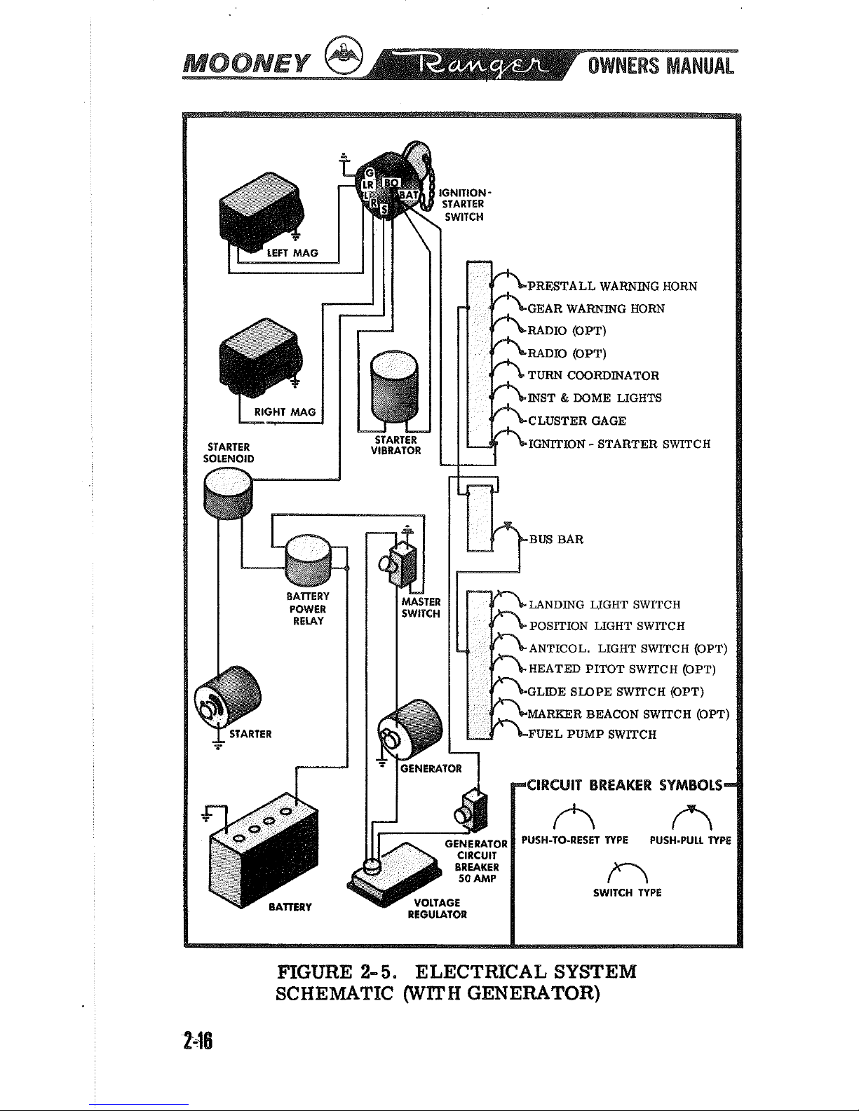
Figure
2-4
illustrates the main circuit breaker panel with its push-to-reset button-type standard equipment circuit breakers. All switch-type circuit
breakers are on the lower left side of the
pilot's instrument
panel.
If
an electrical circuit is found inoperative and its circuit
breaker button
is
in
the out position, it
is
advisable to wait
two or three minutes to permit the breaker contacts
to
cool
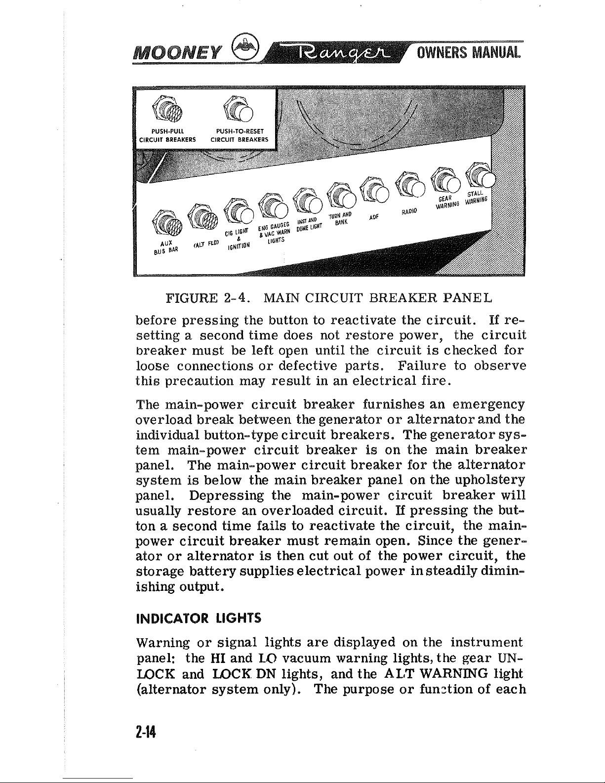
FIGURE
2-4.
MAIN
CIRCUIT
BREAKER PANEL
before pressing the button to reactivate the circuit. If re-
setting a second time does not restore power, the circuit
breaker must be left open until the circuit
is
checked for
loose connections or defective parts. Failure to observe
this precaution may result in an electrical fire.
The main-power circuit breaker furnishes an emergency
overload break between the generator or alternator and the
individual button-type circuit breakers. The generator sys-
tem main-power circuit breaker
is
on the main breaker
panel. The main-power circuit breaker for the alternator
system
is
below the main breaker panel on the upholstery
panel. Depressing the main-power circuit breaker will
usually restore an overloaded circuit.
If
pressing the but-
ton a second time
fails
to reactivate the circuit, the mainpower circuit breaker must remain open. Since the generator or alternator
is
then cut out of the power circuit, the
storage battery supplies electrical power in steadily diminishing output.
INDICATOR
LIGHTS
Warning or signal lights are displayed on the instrument
panel: the
HI
and
LO
vacuum warning lights, the gear
UN-
LOCK
and
LOCK
DN
lights, and the
ALT
WARNING
light
(alternator system only). The purpose or
funztion of each
TURN COORDINATOR
INST & WME LIGHTS
CLUSTER GAGE
IGNITION
-
STARTER SWITCH
ALTERNATOR
FIELD
LAXDING UGHT SWITCH
POSITION LIGHT SWITCH
ANTICOL. LIGHT SWITCH (OPT)
HEATED
PITOT SWITCH (OPT)
GLIDE SLOPE SWITCH (OPT)
MARKER BEACON SWITCH (OPT)
FUEL PUMP SWITCH
CIRCUIT
BREAKER
SYMBOLS
PUSH-TO-RESET NPE PUSH-PULL TYPE
SWITCH NPE
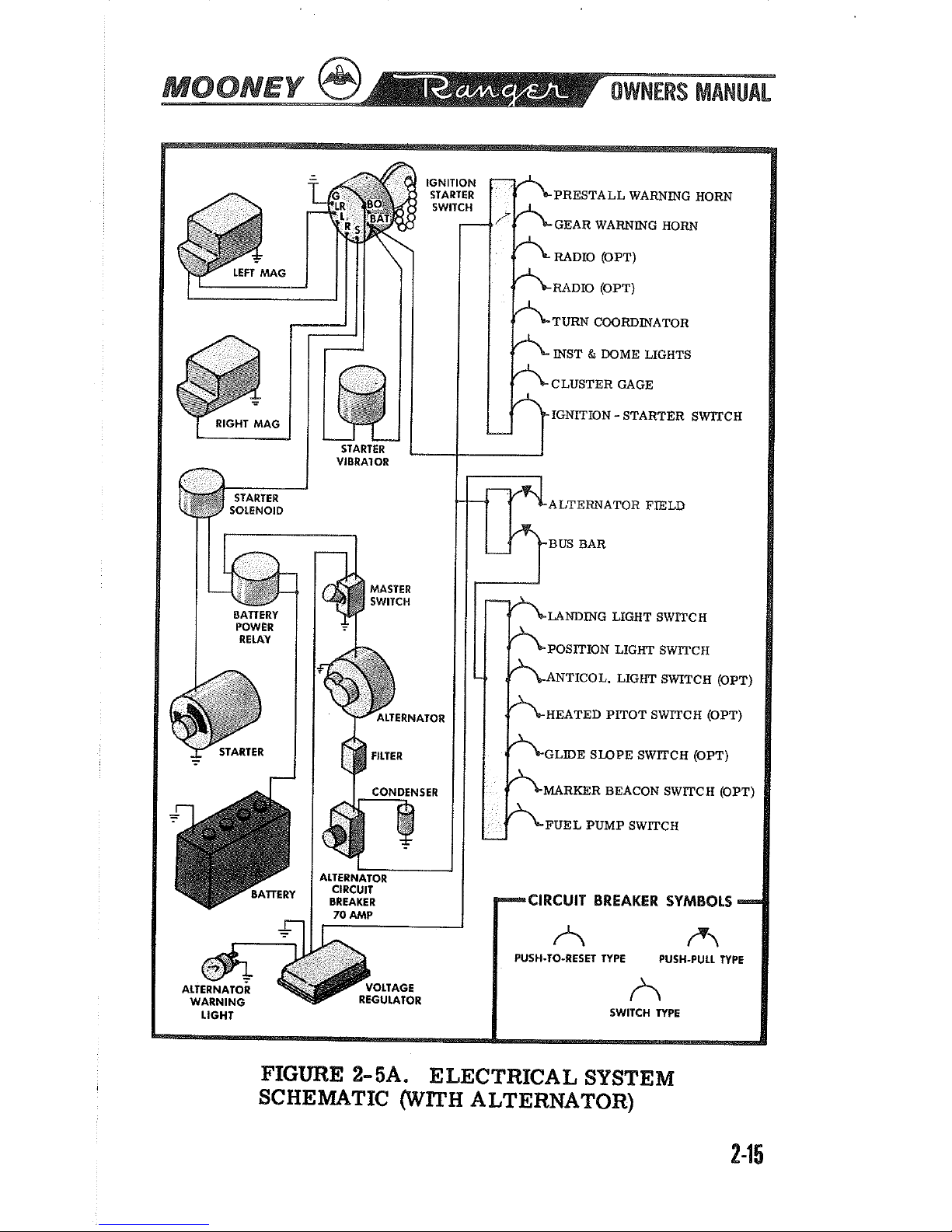
FIGURE
2-
5A. ELECTRICAL SYSTEM
SCHEMATIC (WITH ALTERNATOR)
INST & DOME LIGHTS
CLUSTER GAGE
IGNITION
-
STARTER SWITCH
LANDING LIGHT SWITCH
POSITION LIGHT SWITCH
ANTICOL. LIGHT SWITCH (OPT)
HEATED
PITOT SWITCH (OPT)
GLIDE SLOPE SWITCH (OPT)
FUEL PUMP SWITCH
CIRCUIT BREAKER SYMBOLS
SWITCH
TYPE
FIGURE
2-
5.
ELECTRICAL SYSTEM
SCHEMATIC (WITH
GENERATOR)
of these lights
is
discussed elsewhere in this chapter, All
but the alternator warning light may be dimmed for night
flight. Pressing forward on the lens housings tests the
warning lights; turning the lens housings dims the warning
lights. The
ALT WAWING light does not have a press-to-
test circuit
-
CABlN
LIGHTING
The rheostat knobs in the headliner control instrument
lights, overhead spot lights, and the compass light. Rota-
ting the knob clockwise turns on and increases light intensity. An overhead dome light illuminates the cabin.
CABIN
ENVIRONMENT
HEATING
8
VENTiUTiNG
SYSTEMS
Two
ventilating systems provide cabin environmental con-
trol suited
to
individual pilot and passenger preferences.
Fresh
air
heated
by
the engine exhaust muffler and
COOP
air
from an airscoop on the co-pilot side can be individually controlled and mixed to the desired temperature. The
louvered inlet in the center console
and the left and right
inlets forward of the center console under the instrument
panel control airflow. All three console inlets have adjacent control handles.
The cabin overhead ventilating system works independently
of the cabin heating and ventilating system. Rotating the
knob above the pilot seat extends or retracts the overhead
airscoop to control
air
intake.
Small directional vent deflectors with inner knob volume controls, within easy reach
of each occupant, distribute incoming outside air as individually desired.
The cabin heat control
is
marked
CABIN
NEAT. Opening
 Loading...