

MOONEY
OPERATORS MANUAL
MODEL
M2OC
SERIAL NUMBERS
20-1 147
&
ON
DECEMBER
1974
ISSUE
MOONEY AIRCRAFT CORPORATION
KERRVILLE, TEXAS
78028
m
MANUAL NUMBER
74-20C-O~-~
G#

LOG
OF
PAGES
Page
ONLY
the pages listed herein are applicable
to Model M20
C.
Serial Numbers
Date
..........
Title
12/2/74
............
i
12/2/74
............
ii
12/2/74
............
iii
12/2/74
............
iv
12/2/74
SECTION
I
Page
Date
SECT ION
I
I
Page Date
...........
2-1 12/2/71
...........
2-2 12/2/74
...........
2-3 12/2/74
...........
2.4 12/2/74
...........
2.5 12/2/74
...........
2.6 12/2/74
...........
2-7 12/2/74
...........
2-a 12/2/74
...........
2-9 12/2/74
..........
2- 10 12/2/74
..........
2-11 12/2/74
..........
2-12 12/2/74
..........
2-13 12/2/74
..........
2-14 12/2/74
.......
..
2-15
0,
12/2/74
..........
2-16 12/2/74
..........
2-17 12/2/74
..........
2-18 12/2/74
SECTION
Ill
Page Date
..........
3-1 12/2/74
..........
3-2 12/2/74
3-4
..........
12/2/74
3-5
..........
12/2/74
..........
3-6 12/2/74
3-7
..........
12/2/74
3-8
..........
12/2/74
3-9
..........
12/2/74
..........
3- 10 12/2/74
..........
3-
11
12/2/74
..........
3-12 12/2/74
.
..........
3 13 12/2/74
..........
3-14 12/2/74
..........
3- 15 12/2/74
3-6
..........
12/2/74
..........
3- 16 12/2/74
.
..........
3 17 12/2/74
..........
3-18 12/2/74
..........
3-19 12/2/74
..........
3-20 12/2/74
3-21
..........
12/2/74
..........
3-22 12/2/74
3-23
..........
12/2/74
3.24
..........
12/2/74
3-25
..........
12/2/74
3-26
..........
12/2/74
SECTION
1V
(FAA
APPROVED)
Page Date
4-1
..........
12/2/74
4- 2
..........
12/2/74
4-3
..........
12/2/74
4-4
..........
12/2/74
4-5
..........
12/2/74
4-6
....
.,
.....
12/2/74
.
4 7
..........
12/2/74
4-8
..........
12/2/74
4-9
..........
12/2/74
4-10
.........
12/2/74
LOG
OF
PAGES (CONT.)
SECTION
V
(FAA
APPROVED)
Page
Da
f
e
SECTION
VI
Page
Date
SECTION
VII
/
Page
Date
GENERAL DESCRIPTION
..........
SECTION
SYSTEMS OPERATIONS
...........
SECTION
NORMAL PROCEDURES
...........
SECTION
..................
LIMITATIONS SECTION
........
EMERGENCY PROCEDURES SECTION
................
PERFORMANCE SECTION
.................
SERVICING.
.4
SECTION
This manunl is issued as your operating guide for the
Vooney IIANGEIt. It is important that you--regardless
of
your
previous experience-- carefully read the hand-
boolc
from
cover to cover and review
it
frequently.
IMPORTANT: THIS MANUAL CONTAINS Federal
Aviation Administration APPROVED LIMITATIONS
AND MUST
I'IE CARRIED
IN
THE
AIRCRAFT AT
ALL, TIMES.
All
~~ilormation :incl illustrations in this manual are based
on the latest procluct information available at the time of
1)ut)lic~ttion al)provnl.
'The right is reserved to ~nalce
cliangcs :it any
tillic
without notice.
Every
etfort has been
m:itle 1 o
present the material
in
;L
clc:ir
ancl
convenient
ni:lnllrr to c~iablc you to use the m;i~iii:~l
:is
:I
ready ore-
sent:~tion :incl (*ontent recommenclations is solic.itec1.
Mooney warrants each Aircraft (which includes
its
accessories and equipment) sold hereunder,
to be free from defects in materialand
workmanship under normal use and service when operated
in accordance with Mooneyfs operating instruc-
tions during the period of six
(6)
montlls following
delivery of the Aircraft to
the original retail pur-
chaser or
the first user or during the period of
one
(1)
year follo~ving the date of issue of the original airworthiness certificate for the Aircraft,
whichever
period
fir
st terminates. Mooney does
not
malie ally warranties with respect to equipment
-
and accessories not manufactured by Mooney but
Mooncy assigns
Gny owner of sucll Aircraft (to
the extent same may be assignable) any warra~ities
Mooney has receivecl from the
manufacturers
of
such
ecluipment
ancl
accessories and will,
on
request, provide and execute such instruments as may
be reasonably required to evidence such assignment.
Mooneyfs
obligztion under this warranty
is
limited
to repairing or replacing, at Mooney's option, any
part or parts
which within the applicable warranty
period set forth above, shall be returned, transportation charges prepaid, to Mooney's plant in
Kerrville, Texas or to such other location designated by Mooney, and which upon examination, shall
disclose to Mooney's satisfaction that such part is
defective.
A
new warranty period is not established
for parts replaced hereunder. Parts replaced hereunder are warranted for the remainder of the original
warranty periocl applical~le to Aircraft solcl hereunder.
The
repair or replacement of defective parts under
this warranty shall
be macle by Mooney without charge
for the parts, or
labor for removal, installation and/
or actual
repair of defective parts.
5,
This warranty does not apply to Aircraft, equipment,
accessories, or other parts manufactured or sold by
Mooney which have been subject to misuse, negligence,
accident or improper installation, or
which"1ave been
repaired or altered outside of Mooney's plant in a
way which, in the opinion of Mooney, adversely
affects its performance or reliability. Further, this
warranty does not include
norinal maintenance services (such as engine tune-up, cleaning, control rigging, brake and other mechanical
adjustn~ents,
n~aintenance inspections, etc. ) and the replacelllent
of service items (such as sparlr plugs, brake linings,
filters,
hoses, belts, tires, etc. ) nlade in connection
with such services or required as maintenance,
nor
to normal deterioration of soft trim and appearance
itellis (such as, paint, upholstery, rubber-like items,
etc. ) clue to wear anct exposure.
This warranty shall extend to any owner (hereafter
"Owner") of the Aircraft
making claiill within the
specified warranty period.
THIS WARRANTY BY IdIOONEY IS tIADE EXPRESSLY IN
LIEU OF ANY OTHER P'ARRANTIES EXPRESSED OR
IIIPLIED IN FACT OR BY LAW, INCLUDING ANY IIIPLIED
WARRANTY OF MERCHANTABILITY OR FITNESS FOR A
PARTICULAR PURPOSE, AND IS IN LIEU OF ANY
OTHER
OBLIGATION OR LIABILITY CPJ THE PART OF iiOONEY
TCI ANYONE OF ANY NATURE PIHATSOEVER BY REASON OF
THE
IIANUFACTURE
AND/OR
THE
SALE
AND/OR
THE
USE
OF SUCH AIRCRAF1 , 1100NEY SHALL IN NO E'JENT BE
LIABLE TO ANY OWNER OR TO ANY OTHER PARTY OR
PARTIES FOR SPECIAL, INCIDENTAL OR
CONSECUEN-
TIAL LOSS OR DAiiAGES OR FOR
ANY
OTHER LOSS OR
DAMAGE
TO
PROPERTY
AND/OR INJURY
OR
DEATH
TO
PERSONS OTHER THAN FOR THE PROPERTY DAliAGE TO
SUIIJECT AIRCRAF r PROXIMAl-ELY RESULT
I
I'JG
FRO/, ANY
BRtACH BY MOONEY OF THE AFORESTATED l.!ARRANTYt
IIOONEY NEITHER ASSUMES NOR AUTHORIZES BU'IER OF
ANYONL ELSE TO ASSUllE FOR IT ANY OBLIGATION OR
LIABILITY IN CONNECTION WITH THE AIRCRAFT SUBJECT HEREOF, OTHER THAN THOSE EXPRESSLY SET OUT
HEREIN, NO BILL OF SALE OR TRANSFER OF TITLE
TO THIS AIRCRAFT SHALL NULLIFY THE PROVISIONS
HEREOF,
SECTION
I
.
GENERAL
DESCRIPTION
DESIGN
FEATURES
AIRFRAME
...........................
1.
2
POWERPLANT
........................
1-2
FLIGHT CONTROLS
.....................
1.
3
LANDING
GEAR
.......................
1.
3
SPECIFICATIONS OUTLINE
POWERPLANT
........................
1-3
PROPELLER
.........................
1-4
LANDING
GEAR
......................
-1-4
FUEL & OIL
.........................
-1-5
WEIGHT
&
LOADING
...................
-1-5
BAGGAGE
COMPARTMENT
..............
-1-5

MANUAL
DESIGN
FEATURES
The MOONEY RANGER (M20C) is a low-wing four-
place aircraft with a retractable gear.
A
fourcylinder engine powers the aircraft for economical,
high-performance flight. Licensing under Federal
Aviation Administration regulations assures that
your
Mooney meets the requirements of Normal Category
aircraft.
AIRFRAME
The airframe has a welded, tubular-steel cabin structure enclosed in sheet-aluminum skins. Stressed skins
rivet to main and auxiliary spars in the wing, stabilizer,
and vertical fin. The laminar-flow wing has full wraparound skins with flush riveting over the forward top
two thirds of the wing area.
For pitch trim control, the empennage pivots on the aft
fuselage. A torque-tube-driven jack screw, bolted to
the rear
tail con^
bulkhead, sets the stabilizer angle.
The forward-opening cabin door provides access to both
front and rear seats. The baggage compartment door is
above the wing trailing edge to enable baggage loading
from the ground.
POWER PLANT
The
powerplant is a four-cylinder air cooled engine that
develops 180 horsepower.
A
60-ampere 12-volt alterna-
tor supplies ample electrical power for all standard and
optional equipment at all engine speeds
from warmup to
flight power settings.
The hydraulic propeller governor, using oil pressure for
increasing blade pitch to control engine speed, regulates
the controllable-pitch constant-speed propeller. Spring
and blade aerodynamic forces decrease blade pitch.
FLIGHT
CONTROLS
Conventional dual controls link to the control surfaces
through push-pull tubes. The co-pilot's rudder pedals
are removable.
The Mooney Positive Control (P. C.
)
system
is
standard
equipment.
P.
C.
is
a lateral stability augmentation system that provides a high degree of roll and yaw stability,
thereby enhancing the inherent wings-level flight characteristics of the aircraft. The system works full time
from takeoff through landing but can be easily deactivated
or overpowered for flight maneuvers.
P.
C . allows you,
the pilot, to devote more time to navigation, traffic surveillance, and communications.
LANDING
GEAR
The tricycle landing gear allows maximum taxi vision and
ground maneuvering.
Hydraulic disc brakes and a
steer-
able nose wheel aid in positive directional control during
taxiing and crosswind landings.
The landing gear is electrically actuated. A gear warning
horn along with red and green position lights
help
prevent
inadvertent gear-up landings.
The retraction
syste11l in-
corporates
a
squat switch that prevents gear retraction un-
til a safe airspeed is attained. An emergency gear extension system is provided.
SPECIFICATIONS OUTLINE
POWER
PLANT
TYPE : Four- cylinder, air cooled, horizontally opposed,
$4
*
x,~~~~~
e-
OPERATORS MANUAL
and carbureted engine with a wet-sump hubricating
system.
.......
Model (Lycoming). 0-360-AID
Rated Horsepower
@
2700 RPM
. .
180 BHP
.............
Bore 5.125 IN.
............
Stroke 4.375 IN.
.......
Displacement 361.0
CU.
IN.
........
Compression Ratio 8. 7:l
...
Carburetor, Marvel-Schebler MA-4-5
...
Magnetos, Scintilla S4LN-200 Serie
PROPELLER
TYPE : Constant-speed, hydraulically controlled
propeller with a single-acting governor.
Model (Hartzell)
...
HC-C~YK-
1B/7666 A-2
............
Diameter. 74 IN.
Blade Angle
(@
30 IN. STA)
:
............
Low 130 + 0°
............
High 2g0+20
-
LANDING GEAR
TYPE:
Electrically retracted tricycle gear with rub-
ber
shock discs, steerable nose wheel, and hydraulic
disc brakes.
.......
WheelBase 5FT6-9/16IN.
........
Wheel Treaci
9
FT 3/4 IN.
Tire Size
:
.............
Nose 5.00~ 5
............
Main. 6.00~ 6
Tire Pressure:
..............
Nose 30 PSI
Ma
..............
30 PSI
*
-~~ONEV
OPERATORS
MANUAL
FUEL
&
OIL
Usable Fuel Capacity
.......
52 GAL
Minimum Fuel Octane Rating
(aviation grade)
........
91/96
Oil Capacity
(6
QTS
MIN
for flight)
.
8
QTS
WEIGHT
&
LOADING
Gross Weight
..........
2575 LBS
Approximate
Einpty Weight
(with standard equipment)
...
1525 LBS
Useful Load
...........
1050 LBS
Wing Loading
@
Gross Weight
.
.
15.1
PSF
Power Loading
@
Gross Weight
. .
14.3
PHP
BAGGAGE COMPARTMENT
Maximum Baggage Loading (unless limited
by
weight envelope)
.........
120 LBS
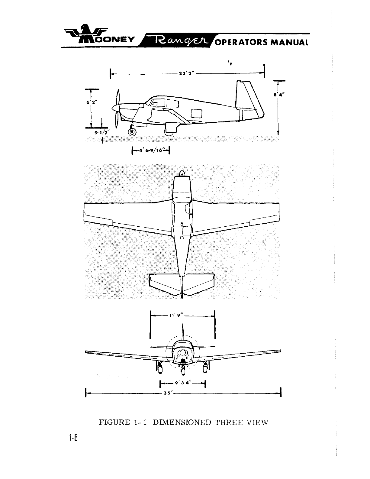
FIGURE
1- 1
DIMENSIONED THREE VIEW
1-6
SECTION
II
.
SYSTEMS
OPERATIONS
POWER
PLANT
.....................
ENGINE CONTROLS 2-4
.....................
IGNITION SYSTEM 2-5
.......................
FUEL SYSTEM 2-5
.........................
OIL
SYSTEM 2-6
ENGINE COOLING
.....................
2-6
.....................
VACUUM SYSTEM 2-6
INSTRUMENTS
.................
FLIGHT INSTRUMENTS 2-7
FLIGHT CONTROLS
............
PRIMARY FLIGHT CONTROLS 2-8
POSITIVE CONTROL
...................
2-9
TRIM CONTROLS
.....................
2-10
WING FLAP CONTROLS
.................
2-10
LANDING GEAR
ELECTRIC GEAR RETRACTION SYSTEM
.....
2-11
EMERGENCY GEAR EXTENSION SYSTEM
.....
2-12
BRAKE
&
STEERING SYSTEMS
............
2-12
ELECTRICAL POWER
ALTERNATOR & BATTERY
...............
2-12
CIRCUIT BREAKERS
...................
2-13
ANNUNCLATOR LIGHTS
.................
2-15
INSTRUMENT
&
PLACARD
LIGHTS
.........
2-16
CABIN LIGHTING
.....................
2-16
CABIN ENVIRONMENT
HEATING & VENTILATING SYSTEMS
........
2-16
WINDSHIELD DEFROSTING SYSTEM
........
2-17
CABIN
SEATS
&
SAFI~Y
BELTS
................
2-18
BAGGAGE
&
CARGO AREAS
..............
2-18
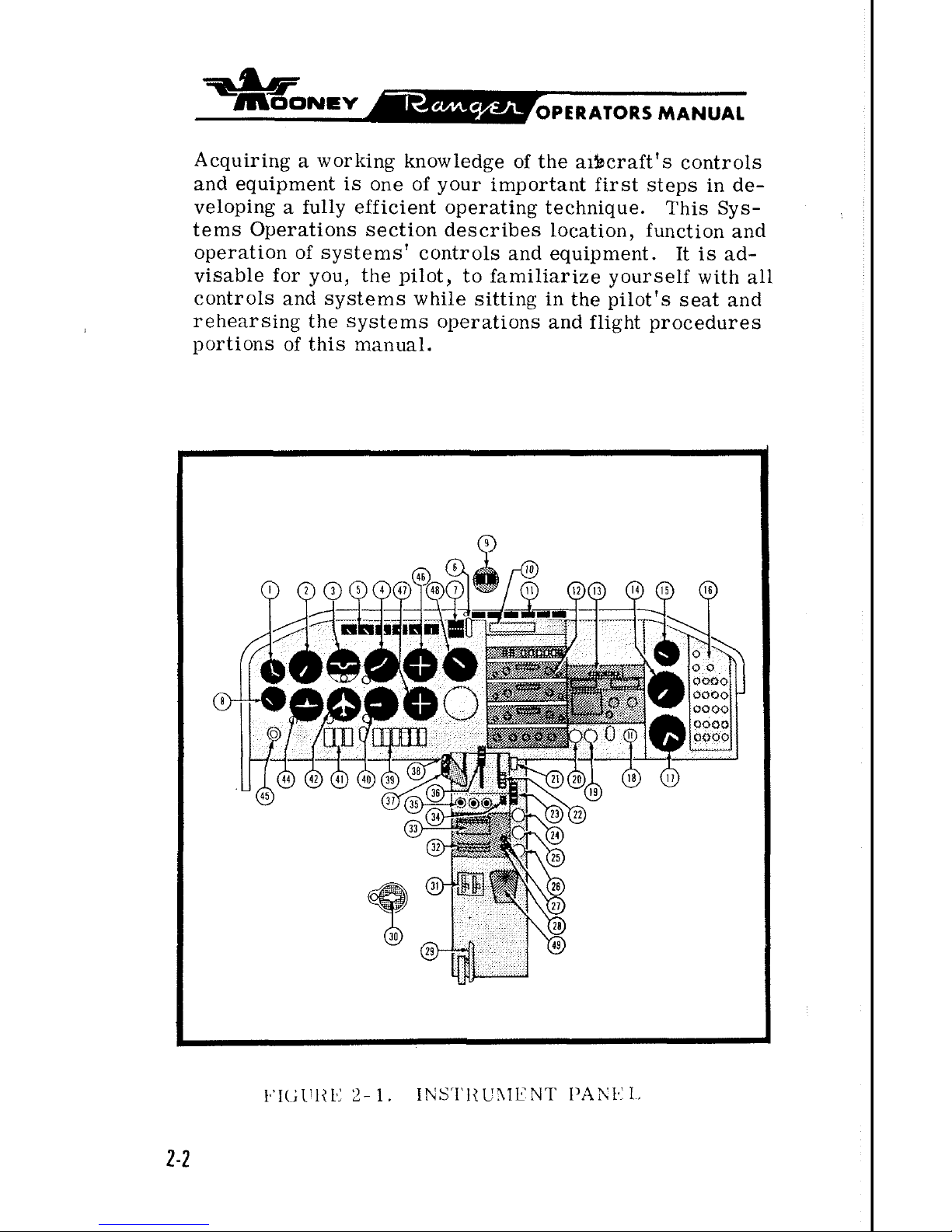
Acquiring a working knowledge of the aibcraft's controls
and equipment is one of your important first steps in developing a fully efficient operating technique. This Sys-
tems Operations section describes location, function and
operation of systems' controls and equipment. It is advisable for you, the pilot, to familiarize yourself with all
controls and systems while sitting in the pilot's seat and
rehearsing the systems operations and flight procedures
portions of this manual.
-
moo~evE
OPERATORS MANUAL
POWER
PUNT
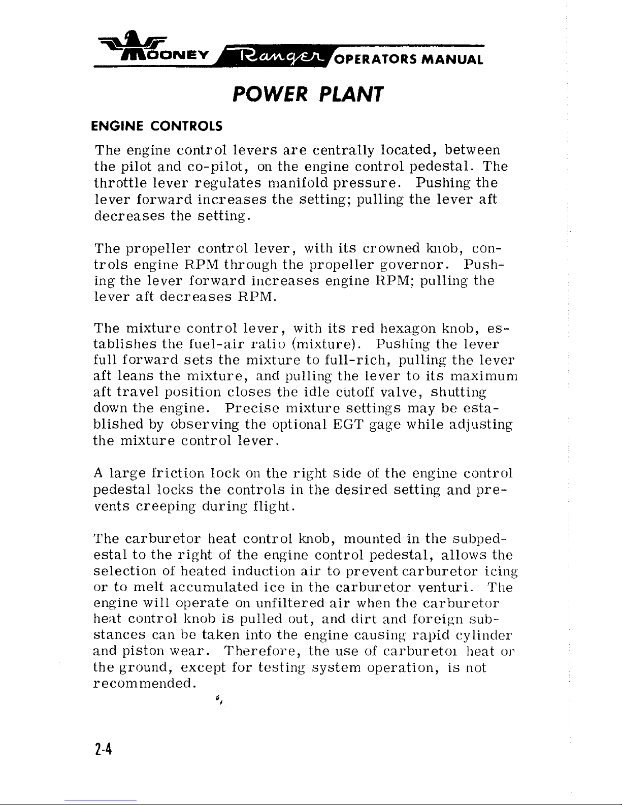
ENGINE CONTROLS
The engine control levers are centrally located, between
the pilot and co-pilot, on the engine control pedestal. The
throttle lever regulates manifold pressure. Pushing the
lever forward increases the setting; pulling the lever aft
decreases the setting.
The propeller control lever, with its crowned
knob, controls engine RPM through the propeller governor. Pushing the lever forward increases engine
RPM:
pulling the
lever aft decreases RPM.
The mixture control lever, with its red hexagon knob, es-
tablishes the fuel-air ratio (mixture). Pushing the lever
full forward sets the mixture to full-rich, pulling the
lever
aft leans the mixture, and pulling the lever to its maximum
aft travel position closes the idle cutoff valve, shutting
down the engine. Precise mixture settings may be established by observing the optional
EGT
gage while adjusting
the mixture control lever.
A
large friction lock on the right side of the engine control
pedestal locks the controls in the desired setting and pre-
vents creeping during flight.
The carburetor heat control knob, mounted in the
subped-
estal to the right of the engine control pedestal, allows the
selection of heated induction air to prevent carburetor
icing
or to melt accumulated ice in the carburetor venturi. The
engine will operate on unfiltered air when the carburetor
heat control
knob
is pulled out, and dirt and foreign sub-
stances can
l-te
taken into the engine causing rapid cylinder
and piston wear. Therefore, the use of
carburetoi heat o13
the ground, except for testing system operation, is not
recommended.
',
-ar
~sJONE~
OPERATORS
MANUAL
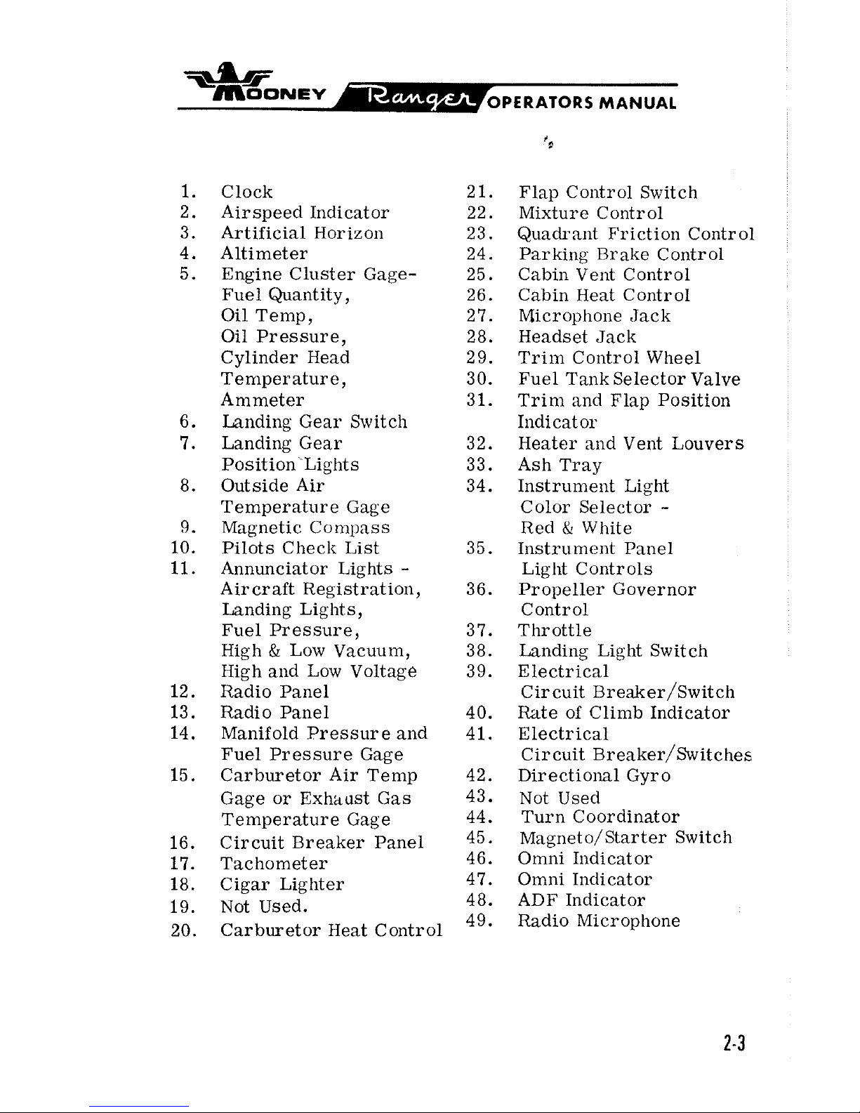
Clock 21.
Airspeed Indicator 22.
Artificial Horizon
23.
Altimeter 24.
Engine Cluster Gage- 25.
Fuel Quantity, 26.
Oil Temp,
2
7.
Oil Pressure, 28.
Cylinder Head
2
9.
Temperature, 30.
Ammeter 31.
Landing Gear Switch
Landing Gear 32.
Position Lights 33.
Outside Air 34.
Temperature Gage
Magnetic
Conlpass
Pilots Checlr List 35.
Annunciator Lights
-
Aircraft Registration, 36.
Landing Lights
,
Fuel Pressure, 3 7.
High
&
Low Vacuum, 38.
High
and Low Voltage 39.
Radio Panel
Radio Panel 40.
Manifold Pressure
and 41.
Fuel Pressure Gage
Carburetor Air Temp 42.
Gage or Exhaust Gas 43.
Temperature Gage 44.
Circuit Breaker Panel
45.
Tachometer 46.
Cigar Lighter 47.
Not Used. 48.
Carburetor Heat Control
49.
Flap
Contr 01 Switch
Mixture Control
Quadrant Friction Control
Parking Brake Control
Cabin Vent Control
Cabin Heat Contr
01
Microphone Jack
Headset Jack
Trim Control Wheel
Fuel
Tank Selector Valve
Trim and Flap Position
Iildicat or
Heater
and Vent Louvers
Ash Tray
Instrument Light
Color Selector
-
Red & White
Instrument Panel
Light Controls
Propeller Governor
Control
Throttle
Landing Light Switch
Electrical
Circuit
~reaker/~witch
Rate of Climb Indicator
Electrical
Circuit
~reaker/~witches
Directional Gyro
Not Used
Turn Coordinator
Magneto/Starter Switch
Omni Indicator
Omni Indicator
ADF Indicator
Radio Microphone
-
~OONEV
OPERATORS MANUAL
All engine instruments except the EGT gage, tachometer and fuel and manifold pressure gages are grouped
in the left instrument panel. Color arcs on instrument
faces mark operating ranges.
Proper interpretation of
engine instrument readings
is
essential for selecting
optimum contr
01 settings and for maintaining maximum
cruise fuel economy.
Engine limitations are given in
Section
IV.
IGNITION SYSTEM
The left magneto has a set of fixed retard breaker points
that aid in smoother, easier starting. A battery-powered
starting vibrator supplies a long-duration, boosted spark.
The starter-ignition switch, mounted on the left of the instrument panel, combines both ignition and starting functions. Turning the ignition key clockwise through
R,
L,
and BOTH to the START MAG position and then pushing for-
ward on the key and receptacle engages the starter. Re-
leasing the key when the engine starts allows the switch to
return by spring action to the BOTH position.
For safety,
the starter-ignition switch must be left at OFF when the
engine is not running.
FUEL
SYSTEM
Two integral sealed sections carry the fuel in the forward
inboard area of the wings.
Full fuel capacity
is
52
gallons.
There are sump drains
at
the lowest point in each tank for
taking fuel samples to check for sediment contamination
and condensed water accumulation.
Section VII discusses
the fuel sampling procedure.
The .recessed three-position fuel selector handle on the
cabin floor sets the selector valve below the floorboard
for LEFT tank, RIGHT tank, or the OFF position. The
fuel selector
va%e assembly contains a valve for draining
condensed water and sediment from the lowest point in the
=.LIF
~OONEV
OPERATORS
MANUAL
fuel lines before the first flight of the da~ and after
each refueling. Section
VII discusses the selector
valve flushing procedure.
Fuel feeds from one tank at
a
time to the selector valve
and through the electric fuel pump
enroute to the enginedriven pump and the carburetor unit. Electric fuellevel transmitters in the tanks operate fuel gages in the
engine cluster. The master switch actuates the fuel
quantity indicator system to maintain an indication of
fuel remaining in each tank.
The fuel pressure gage
registers fuel pressure in the line to the carburetor.
Vents in each fuel tank allow for overflow ventilation.
OIL SYSTEM
The engine has a full-pressure wet-sump oil system with
an
8
quart capacity. The automatic bypass control valve
routes oil flow around the
,oil cooler when operating tem-
peratures are below normal or when the cooling radiator
is
blocked.
The engine oil should be kept at
6
to 8 quarts.
Lycoming
Service Instruction
1014
(latest revision) gives recom
-
mended oil specifications and oil change intervals.
ENGINE COOLING
The down-draft engine cooling system provides ground
and
inflight power plant cooling.
Engine baffling directs
air
over and around the cylinders and out the cowl flap
openings.
Cowl flap doors are fixed in
a
position that
allows proper air flow on the ground and in flight.
VACUUM
SYSTEM
An engine-driven vacuum pump supplies suction for the
vacuum-operated gyroscopic flight instruments and the
MANUAL
Mooney Positive Control system. Air entering the
vacuum-powered instruments is filtered; hence,
sluggish or erratic operation of vacuum-driven instruments may indicate that a clogged vacuum filter element
is
preventing adequate air intake.
The vacuum an-
nunciator light will illuminate steadily for
Hi
Vac
and flashes for Laow Vac indication.
INSTRUMENTS
FLIGHT INSTRUMENTS
All
primary flight instruments are grouped on the shockmounted flight panel directly in front of the pilot's seat.
Optional gyro instruments may be installed in the standard
T-grouping with the attitude gyro at top center and the
directional gyro immediately below. The standard airspeed
indicator and sensitive altimeter cross the
"T".
The stan-
dard turn coordinator and optional vertical speed indicator
at
left of center complete the flight instrumentation.
The magnetic compass
is
mounted on the windshield post
above the instrument panel. A remote indicating gage is
installed in the left of the flight panel. There
is
space
and lighting for four optional radio indicators on the right
side of the flight panel.
&bF
~OONEV
PERATORS
MANUAL
A
pitot tube, mour~ted on the lower surfaw of the left
wing, picks up airspeed indicator ram air.
A
heated
pitot prevents pitot tube icing when flying in moistureladen air. A drain valve is located on the forward
bottom skin of the left wing just outboard of the wing
fillet. Static ports on each side of the tail cone supply
static air pressure for the altimeter, the airspeed
indicator, and the vertical speed indicator. A drain
valve is located on the fuselage bottom skin below the
tail
cone access door.
An alternate static
pressure
source valve will
be
found under the left side of the
flight panel.
A
stall warning horn, mounted in the cabin head liner
and triggered by a sensing vane on the left wing leading
edge, will sound when airspeed drops to near stall
speed. The sound becomes steady as the aircraft
approaches a complete stall.
There are two landing gear position lights; one is a green
GEAR
DOWN' light and the other is a red IN-TRANSIT light.
No, light shows when the gear is full up. Inadvertent posi-
tioning of the gear switch to the up position while the air-
craft is on the
ground will cause both the red and green
to
be
illuminated and the warning horn to souild if the
throttle is closed.
FLIGHT
CQNTROLS
PRIMARY FLIGHT CONTROLS
Push-pull tubes with self-aligning rod end bearings actuate
the primary flight control surfaces. Beveled aileron trail-
ing edges help reduce pilot control forces required for flight
maneuvering.
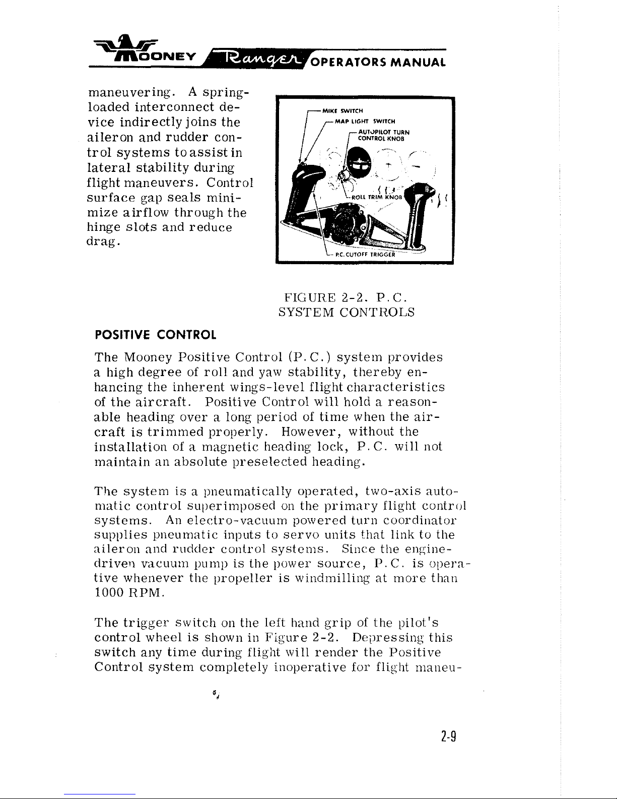
A
springloaded interconnect device indirectly joins the
aileron and rudder control systems to assist in
lateral stability during
flight maneuvers. Control
surface gap seals minimize airflow through the
hinge slots and reduce
drag.
MAP
LIGHT
SWITCH
I'
FIGURE
2-2.
P.C.
SYSTEM CONTROLS
POSITIVE CONTROL
The Mooney Positive Control (P.
C.)
system provides
a high degree of roll and yaw stability, thereby en-
hancing the inherent wings-level flight characteristics
of the aircraft.
Positive Control
will
hold a reason-
able
heading over a long period of time when the air-
craft is trimmed properly.
However, without the
installation of
a
magnetic heading lock, P. C. will not
maintain an absolute preselected heading.
The system
is
a pneumatically operated, two-axis auto-
matic control
sul)erimposecl on the primary flight control
systems.
An
electro-vacuum powered turn coordinator
supplies pneumatic inputs to servo units that link to the
aileron
and rudder control systems. Since tlte engine-
clrivert vacuum
pump
is the power source,
P.
C.
is opera-
tive whenever the propeller
is
windmilling at more than
1000
RPM.
The trigger
switch on the left hand grip of the pilot's
control wheel
is
shown in Figure 2-2. Depressing this
switch any time during
flight will render the Positive
Control system completely inoperative for flight
maneu-
MANUAL
vers or manual flying. When the cutoff gwitch
is
re-
leased, the aircraft will return unassisted to
wings-
].eve1 flight.
P.
C.
can be manually overridden with little
effort if the system should malfunction. Manually
over-powering the system will not damage the aircraft
or the
P.
C
.
components.
The roll-trim knob on the turn coordinator, as shown in
Figure 2-2, provides an aileron trim function through
the
P.
C.
system. Rotating the ltnob trims the aircraft
about its roll axis to compensate for asymmetrical fuel
and passenger loadings.
The
P.
C.
systeim
is
installed to help alleviate pilot
fatigue.
But
lilte any other system in the aircraft,
P.
C
must be monitored for proper functioning.
TRIM CONTROLS
For pitch trim control, the entire empennage pivots on
the tail
cone attachment points to increase or decrease
the horizontal stabilizer angle. This design allows flight
trim establishment with
minimum control surface deflec-
tion.
A
trim indicator located on the console indi-
cates stabilizer trim position.
Forward rotation of
the trim wheel lowers the nose; rearward rotation
nises the nose in flight.
WING FLAP CONTROLS
The flap control on the right
of
the engine control pedestal operates the electrically-actuated wide-span wing
flaps. Moving the control to the
UP
position, retracts
the
flaps. The position of the flaps can be noted from
the flap position indicator.
The control has a
detent
to assist the pilot in detecting the takeoff flap setting.
*
~OONSV
OPERATORS
MANUAL
ELECTRIC GEAR RETRACTION SYSTEM
The two-position electric gear control switch, iden-
tified by
its
wheel-shaped knob, is located at the top
of the instrument panel above the
throttle.
There are three ways to see that the electrically-
actuated gear
is
down-and-locked:
(1)
The green gear -down annunciator light illumi-
nates.
(2)
The indicator marks align as seen on the floorboard visual gear-position indicator.
(3)
The gear warning horn does not sound at
approach power setting of below
12
inches mani-
fold pressure.
A
green GEAR
DN
light, a red IN TRANSIT light,
and a warning horn provide visual and audible gear
position signals. The green light (GEAR DN) shows
continuously when the gear is fully extended. Both
lights are out when the gear is fully retracted.
The illuminated gear-down position indicator in the
floorboard aft of the center console has two
marks
that align when the gear is down.
Retarding the throttle below
12
inches inanifold
pressure causes the gear warning horn to enlit a
regular, intermittent tone unless the gear
is
down-
and- locked.
A mechanically actuated "Squat-Switch" in the re-
traction system prevents
inadvertent landing gear
retraction. The safety switch is not intended to
substitute for the gear switch in keeping the gear
extended while taxiing, taking off, or landing.
EMERGENCY GEAR-EXTENSION SYSTEM
The emergency gear extension handcrank on the left upholstery panel near the pilot's knee
is
for manually driving
the electric gear actuating motor to extend the gear
if
the
electrical system should malfunction. Section
IV
dis-
cusses the emergency gear extension procedure.
BRAKE 8 STEERING SYSTEMS
The main gear wheels incorporate self-adjusting disctype hydraulic brakes. The pilot's rudder pedals have
individual toe-actuated brake cylinders linked to the
rudder pedals. Depressing the toe pedals and pulling out
the parking brake control on the console sets the
brakes
fax
parking. Pushing the parking brake control
forward releases the brakes.
It
is
inadvisable to set the parking brake when the brakes
are overheated after heavy braking or when outside temperatures are unusually high. Trapped hydraulic fluid
may expand with heat to damage the system. Wheel chocks
are normally used for long-term parking and mooring.
Rudder pedal action steers the nose wheel. Gear retrac-
tion relieves the rudder control system of its nose wheel
steering and centers the wheel to
permit retraction
irito
the nose wheel well.
ELECTRICAL
POWER
ALTERNATOR 8 BATTERY
A
35-ampere-hour
12
volt negative-ground storage battery
under the left engine cowl and a 60-ampere alternator
$*
supply electrical power for equipment operation. The
ammeter in the engine instrument display indicates
battery charging rate.
A
power loss in the alternator
or voltage regulator will be shown as
a
discharge read-
ing on the ammeter; a discharged battery will be indi-
cated
as
a
high-charge reading.
The voltage regulator adjusts alternator output to current
load while maintaining a constant voltage level.
A11
alter-
nator
warning light illuminat es steadily w hen voltage
regulator output exceeds voltage limits. It flashes when
the voltage
is
low.
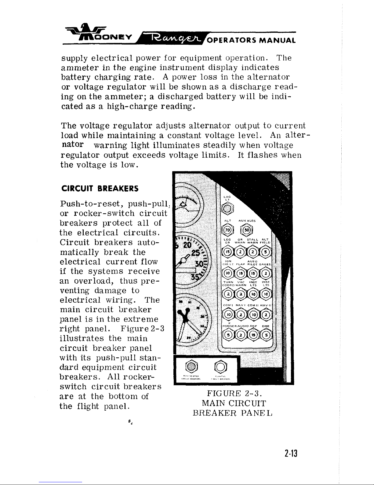
CIRCUIT
BREAKERS
Push-to-reset, push-pull:
or rocker-switch circuit
breakers protect all of
the electrical circuits.
Circuit breakers auto-
matically break the
electrical current flow
if
the systems receive
an overload, thus pre-
venting damage to
electrical wiring. The
main circuit breaker
panel
is
in the extreme
right panel. Figure
2-3
illustrates the main
circuit breaker panel
with its push-pull standard equipment circuit
breakers. All
rocker-
switch circuit breakers
are
at
the bottom of
FIGURE
2--3.
the flight panel. MAIN CIRCUIT
BREAKER
PANEL
ias
~OONEV
OPERATORS MANUAL
*a
LANIIING GEAR
GEAR WARNING
STALI. WARNING
ALTERNATOIT FIELD
IGNITION
&
CIG LTR
A U'I'O1'11.OT (OW"
INSTl{lJh1EN1'S
I'C TITIGGEIT
8.
'TUIIN COOI~rl
VACUUhl WAftNING
INSTRUMENT LTS (LEFT)
INSTRUMENT LTS (RIGlfT)
FUEL
BOOS'I'
PUMP
PITOT HEAT
STRODE 1,IC;HT
ROTATING BLACON (OPT)
RADIO
MASTFII
NAV I (Ol"1
i
COM
11
(01"I'I
NAV 11 101"1'l
'I'I~ANSl'ONI>I~~II lOl>'l'l
AUDIO (OPT)
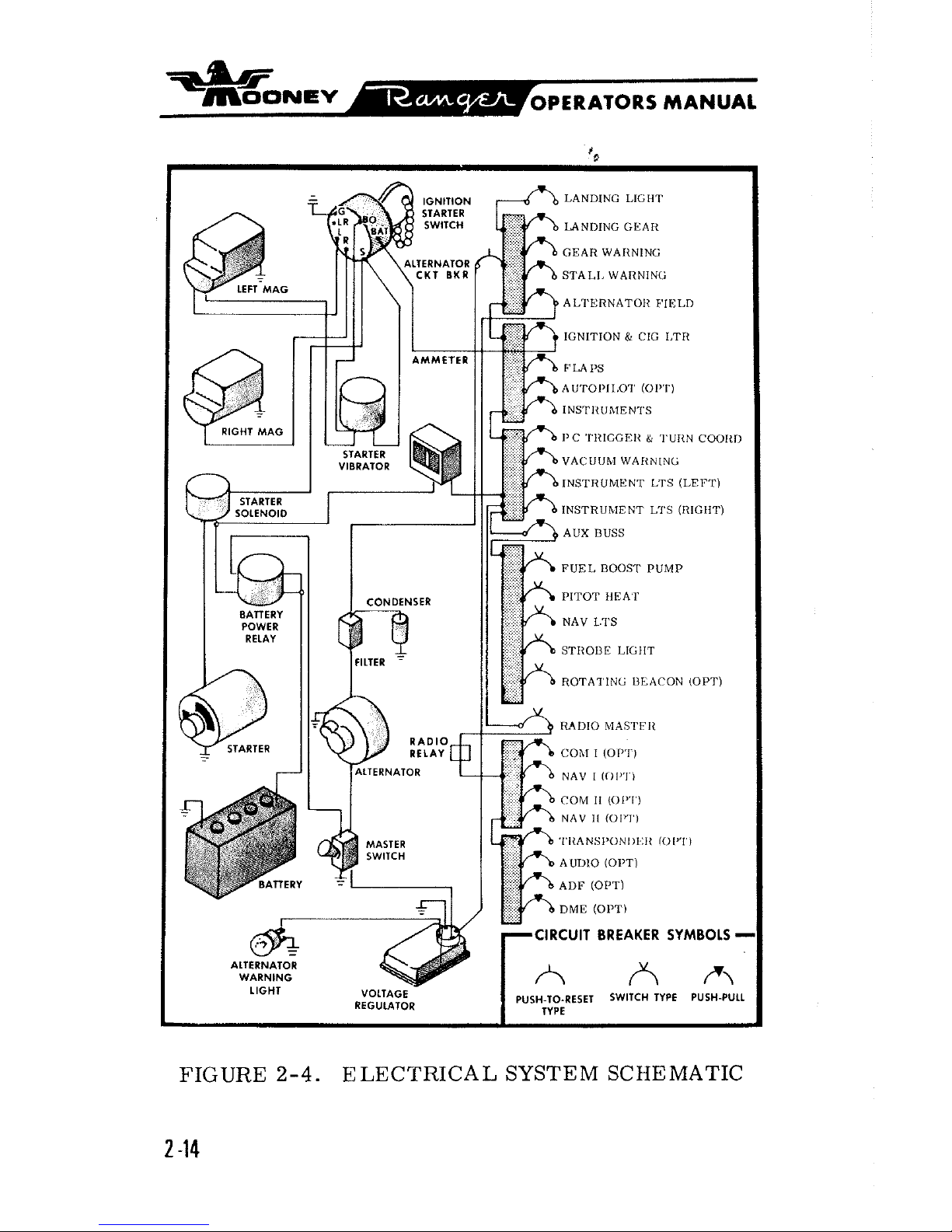
FIGURE
2-4.
ELECTRICAL SYSTEM SCHEMATIC
2 -14
idb
~OONEV-
OPERATORS
MANUAL
The alternator push-pull circuit breaker on the main
breaker panel furnishes an emergency overload break
between the alternator and the individual push-pull
circuit breakers. Resetting the alternator circuit
breaker will usually restore an overloaded circuit. If
pressing the button a second time does not reactivate
the circuit, the alternator circuit breaker must re-
main open and the alternator-field circuit breaker must
be pulled out to break the alternator excitation circuit.
Since the alternator is then cut out of the power circuit,
the storage battery supplies electrical power in steadi-
ly diminishing output with the master switch on.
The alternator-field push-pull circuit breaker furnishes
an emergency break in the alternator field excitation
circuit in the event of alternator or voltage regulator
malfunction. If the regulator output voltage exceeds
limits, the red alternator warning light illuminates
steadily. Turning off all radio equipment, and then
turning master switch off and
on, will reset the voltage
regulator. The alternator annunciator
light should
remain out. If the alternator light comes on again,
pulling out the alternator-field circuit breaker cuts the
alternator out of the power circuit.
Once again the bat-
tery is the only source of electrical power; therefore,
all electrical
equipmerlt not essential for flight should
be turned off and the flight terminated as soon as practical to correct the malfunction.
ANNUNCIATOR LIGHTS
The landing gear lights are at the top of the instrument
panel by the landing gear switch. Annunciator lights

for the registration number, landing light, nlternator
,
vacuum, and fuel pressure are in the glare s hielcf.
The purpose and fullction of each of these lights is
discussed elsewhere in this section.
INSTRUMENT
&
PLACARD LIGHTS
All
instrun1e:lt faces 2nd placards are floodlighted by
light bulbs in the glare shield. Rheostat lulobs on the
control quadrants control
the intensity of instru~nent
ancl placard lighting.
Roi
ating the knobs clockwise
tul.11~
011
;III{I
il~(-l.(';\s~s light intcllsity.
CABIN LIGHTING
An
ad~ust~lble eyetx111 dome light illuminates the c.aI,it~
ancl also serves
ns
a bacliup ~i)o!light for illuminating
the
instrume:~t ;)anel; its
OV-OFF-DIM
switch is slight-
ly forward ancl
to
the right of the dsmle light.
CABIN ENVIRONMENT
HEATING
&
VENTILATION SYSTEMS
T\vo ventilating systems l~rovicle cabin environmental con-
trol
suited
to
indivittual pilot ancl passenger prefcre!~.:es.
I.'resh
air healotl i)y the :tn;:ino r:xlt;i?rst. ml~ifler
,
nntl
cool
air I'rol.r1 ail ail-scoop oil
thit
c:o-pilot sicle, can I)e indivicl-
u;\lly controllecl :\ntl tnixed to the clesireil temlicrnture.
The left side fresh-air scoop has an adjustable eyeball
inlet near the pilot's knee.

*
'\-~OONEV
OPERATORS
MANUAL
The cabin overhead vcntilaling systenl worl<s independently of the cabin heating and ventilating systenl.
Rotating the
knob above the pilot seat eXte1lds or re-
tracts the overhead
airscoop t:, control air intake and
to prevent air-buffeting at high cruising speeds.
Small
directional vent deflectors @ith inner knob air volumn
controls, within easy reach of each occupant, distribute
incoming outside
air
as
individi~ally desired.
The cabin heat control is marked CABIN
HEAT.
Opening
the side
;xirscoop control (labeled CABlN VENT) and
setting the cabin heat control turns on cabin heat.
To
lower cabin temperature, the cabin heat control is
pushed toward the
OFF
j~osition. Conlpletely closing the
cabin heat control and fully opening the cabin vent
con-
tr 01, with the overhead :tirscoop extended, supplies
maximum fresh air circulation. In case of engine fire,
the cabin heating
systenl must be turned off.
The right side
airscoop has outlets undel- the
side
panel
for
installatio!~ of radio or autol~ilot ecluil)ment cooling
ducts.
WINDSHIELD DEFROSTING SYSTEM
The defrosting system talces warm air from the cabin
heating system
ductwork and distributes this air over the
windshield interior surfaces. The system works full
time without a separate control.

*
~OONEV
OPERATORS MANUAL
SEATS & SAFETY BELTS
The front seats are individually mounted and may be
adjusted fore and aft to fit individual comfort preferences. Resetting a seat back is accomplished by
pulling the seat back forward, rotating the large cam
selector
lmob at the lower back juncture, and allowing
the back to return to the new position. The rear seat
back can be adjusted by leaning forward in the seat,
pulling the catch lever at the forward end of the side
panel arm rest, and adjusting the seat back to the
desired position.
Safety belts, if
worn properly, keep occupants firmly in
their seats in rough
air and during maneuvers.
These
belts are mechanically simple
nuct conlfortal~le to wear.
They are
attached to the seat so the seat can be moved
without readjusting the belt.
BAGGAGE & CARGO AREAS
The baggage compartnlent has
15
cubic feet
of
baggage
or cargo space and two pair of floor
tiedo\vn straps. The
loose equipment, consisting of
tiedown eyebolts, jack-
points,
tiedown rings, a fuel sampling cup, and a towbar
is stowed in the baggage compartment. The rear seat
backs can be removed for additional cargo space by pulling the
springloacled lock pins at the seat bac.1~ I~ase
a!ld
sliding the seat back rearward.

SECTION
Ill
.
NORMAL
PROCEDURES
GROUND OPERATIONS
PREFLIGHT
.........................
3-2
...................
PREFLIGHTCHECK 3-3
....................
BE
FORE STARTING 3-5
..............
BEFORE-STARTING CHECK 3-5
STARTING
..........................
3-6
.....................
STARTINGCHECK 3-7
...............
Flooded- Engine Clearing 3-8
Cold- Weather Starting
................
3-9
......................
Hand Cranking 3-9
WARMUP & TAXILNG
...................
3-9
BEFORE-TAKEOFF CHECK
..............
3-11
FLIGHT OPERATIONS
TAKEOFF
.........................a.
3-12
.............................
CLmB 3-13
............................
CRUISE 3-15
STALLS
............................
3-17
SPINS
..............................
3-18
POSITIVE CONTROL
..................
-3-20
FUEL MANAGEMENT
...................
3-21
INFLIGHT RESTARTING
................
3-22
LETDOWN
.........................
-3-22
BEFORE- LANDING CHECK
...............
3-23
LANDING
...........................
3-23
AFTER.LANDING
....................
-3-25
SHUTDOWN CHECK
....................
3-25

db
m00hlcv
OPERATORS
MANUAL
Before flying your Mooney, it is necessary that you become thoroughly familiar with all techniques needed to
operate its systems and equipment safely
and efficiently.
This section of the manual provides you with a quick and
easy reference to normal operating procedure recommend-
ations. Checklist procedures are enumerated in steps that
cover cockpit contr
01s and instruments in left-to-right and
top-to-bottom patterns. These procedures are intended to
assist you in developing good flying techniques under average conditions. While close attention to each step is
impor-
tant for safe and efficient operation, sound judgment may
occasionally be called for in making exceptions when circumstances require
a
deviation in operating procedure.
GROUND OPERATIONS
PREFLIGHT
In addition to completing the preflight check, visually in-
spect all of the
airwaft exterior prior to each flight with
particular attention to detection of loose rivets and dents.
When
checking under the aircraft, look for fuel and oil
leaks indicated by oil runs or fuel dye stains.
WARNING: Check the aircraft weight and balance
before proceeding with the flight. Consult the
Weight
&
Balance Record, furnished in the air
-
plane file, for detailed data needed to calculate
load distribution and limitations.
Standard atmospheric
teinperatures are below freezing
above
8000
feet altitude, and it is possible that condensed
water in the fuel lines will freeze to cause fuel starvation.
Therefore, always drain the fuel selector
~~11111
(as de-
scribed in Section
VII) at each preflight inspection.

*
mm
OPERATORS MANUAL
FIGURE 3-1.
PREFLIGHT WALK
AROUNU LIIAGIZAM
PREFLIGHT CHECK
1.
Ignition Switch--OFF.
Master Switch--ON to check outside lights,
then OFF.
Fuel Selector Drain--Selector handle on R; pull
ring and hold for five seconcls.
Repeat pr ocedure
with selector handle on
L.
2.
Instrument Static Port-- UNOBSTRUCTED.
Tail
Tiedown-- RE MOVE.
3. Empennage--CHECK.
Remove all ice, snow, or frost.

4.
Tail Cone Access Door--SECURE?
Instrument Static Port- -UNOBSTRUCTED.
Static System Drain--CHECK.
5.
Wing Skins--CHECK.
Flap and Attach Points--CHECK.
Aileron and Attach Points- -CHECK.
Wing Tip and Navigation Light-
-
CHECK.
Remove all ice, snow, or frost.
6.
Left Wing Leading Edge--CHECK.
Pitot Tube and Stall Switch Vane-- UNOBSTRUCTED.
Fuel Tank--CHECK QUANTITY; SECURE CAP.
Chock and Tiedown--REMOVE.
Left Main Gear Shock Discs and Tire--CHECK.
Fuel Tank Sump Drain--SAMPLE
.
Pitot System Drain--CHECK.
Tank Vent-
-
UNOBSTRUCTED.
Fuel Selector Drain Valve-
-C LOSED.
Windshields--C LEAN.
Left
Side Engine Cowl Fasteners-- SEC URE.
7.
Propeller--CHECK for nicks and cracks.
Forward Engine Components--CHECK starter,
alternator belt, etc.
Induction Air Filter--CHECK clean and sealed.
Landing Light--CHECK.
Nose Gear--CHECK tire; check for towing damage.
Shock Discs--CHECK.
8.
Right Side Engine Cowl Fasteners- -SECURE.
Engine Oil Level--CHECK (full for extended
f
lig it).
Windshield--CLEAN.

*
~OONEV
OPERATORS MANUAL
Fuel Tank Sump Drain--SAMPLE
.
Tank Vent-- UNOBSTRUCTED.
Chock and Tiedown--REMOVE
.
Right Main Gear Shock Discs and Tire- -CHECK
Fuel Tank--CHECK QUANTITY; SECURE CAP.
9.
Right Wing Leading Edge--CHECK.
Wing Skins--CHECK.
Wing Tip and Navigation Light--CHECK.
Aileron and Attach Points--CHECK.
Flap and Attach Points--CHECK.
Remove all ice, snow, or frost.
10.
Baggage Door
-
-
SE C URE
.
BEFORE STARTING
After everyone has entered the aircraft, close and latch
the door.
Be sure all baggage is secure and that all
necessary charts, computers, and other loose items are
aboard and securely stowed so that they will not be
thrown about the cabin if rough air
is
encountered in
flight. See that all safety belts are fastened and that
the seats are adjusted and locked in comfortable positions. With the pilot's seat properly set, you should be
able to fully deflect all flight controls. Be sure
thereis
a flashlight aboard for night flights.
BEFORE STARTING CHECK
1.
Fuel Selector Handle--SET for fuller tank.
2.
Parking Brake Control--PULL ON.
3.
Ignition and Master Switches--OFF.

*
~OONBV~
OPERATORS MANUAL
5.
Landing Gear Switch- - DOWN.
*9
6.
Mixture Control--IDLE CUTOFF
7.
Propeller-- HIGH RPM.
9.
Boost Pump--OFF.
10.
A11 External Light--OFF.
11.
Radios--ALL OFF.
12.
Cabin Heat--OFF.
13.
Main Circuit Breaker Panel--CHECK.
STARTING
Before starting the engine, make sure the surrounding
area
is
clear. It is good practice to call "CLEAR"
before engaging the starter, and to direct the propel-
ler blast to an open area before running up the engine.
To prevent
prcpeller damage, keep engine RPM low
when operating on loose gravel.
The engine will require
some priming for smooth starting.
The standard fuel system does not incorporate a separate
priming system;
priming is accomplished by pumping the
throttle with the electric fuel pump turned on and the mixture control lever in the FULL RICH position. For
nornlal
starts, pump the throttle twice. A cold engine will require
three or more "priming shots" depending upon the ambient
temperature.

'rhe
sc'lrti
heckli list
is recnmmendr el~xl
starti, edures; however, unde~
,lit-
climatic,
conditicli' dter the starting procetl~ A to accommod:;
existing 8 iiditions. If the engi11~. does not start aftel
10
or
15
~jrlds of cranking, discontinue cranking and
al-
1
t
t$<
rtzr to cool for approximately five minutes
t)efox I-ranklllg adgain.
A11
\$
1,1!:
the
sf
nrter to cr!ol in-
terrnltt ~ntly will
p~olcnlv
*
-
tar
life.
The engine
is
air-r2r r:ooled and depel
3
on the
forward speed of
if
tincraft
to maintain
j3,
$per cooling.
Particular
egre
is
necessary, therefore,
:
hen operating
the engine
oil
the ground. To help prei
s
overheating,
always
!IC;;~
the aircraft into the wind tl~d avoid pro-
longed
engitle ground operation.
STARTING
CHECK
1.
Master Switch--ON
2.
Fuel Quantity Indicators riECK for conformity
to observed quantity.
3.
Annu~~ciator 1,ights- IyRESS to TEST.
5.
Electric Fuei Pump--ON.
6.
Mlxture Control- --Open to FULL RICH.
7.
Throttle--PUMP 'I'WICE to prime engine; then
OPEN
approximai ely one-quarter.
8.
Ignition Starter hitch--turn to "START" and PUSH
forward. When engine starts, release to "BOTH".

*
~OONEV
OPERATORS MANUAL
1.
Oil Pressure Gage--25 PSI MIN (If there
is
no
pressure indication within
30
seconJs, PULL
mixture control to IDLE CUTOFF and check oil
system.
)
12.
Carburetor Heat--ON momentarily to check operation. (RPM should drop.
)
CAUTION: Limit the use of carburetor heat
during ground operation to the time required
to make sure the system
is
functioning prop-
erly.
Heated carburetor air does not pass
through the air filter; consequently, dust,
dirt, and foreign substances can be drawn into
the engine to cause accelerated cylinder and
piston ring wear.
13.
Fuel Pressure Gage--GREEN ARC
14.
Lights--As required.
15.
External lights- -ON as required.
16.
Pitot Heater--CHECK and note ammeter de-
flection.
17.
Radios--QN and CHECK.
18.
Stabilizer Trim Indicator--TAKEOFF.
19.
Fuel Selector I-Iandle- - CHECK right and left.
Flooded- Engine Clearing
1.
Throttle--FULL OPEN.
2.
Mixture Control--IDLE CUTOFF.

*
-~OONEV
--
OPERATORS MANUAL
3.
Electric Fuel Pump--OFF
4.
Ignition Starter Switch--turn to "START" and
PUSH
forward.
5.
Throttle--RETARD when engine starts.
6.
Mixture Control--Open slowly to FULL
RICH.
Cold- Wea ther Starting
The starting procedure for a cold engine is the same as
the normal starting procedure, except that additional
priming (mixture control set at FULL RICH) may be
necessary. During extremely cold weather it
is
advisa-
ble to preheat the oil and engine compartment with
ground heaters
.
Hand Cranking
Hand cranking is not recommended.
WARMUP
&
TAXIING
Allow the engine to warmup at
1000
to
1200
RPM; normally,
taxiing will sufficiently warm the engine. The engine is
warm enough for takeoff when it will develop full RPM and
when the throttle can be opened without backfiring, skipping,
or
a
reduction in oil pressure.
Release the parking brake,
and as the aircraft moves forward apply the toe brakes
lightly to check brake effectiveness.
Nose wheel steering,
through rudder pedal action,
is
ordinarily sufficient for
ground maneuvering. But, when necessary, make tighter
turns by applying inside braking.
CAUTION: Never rely on the retraction safety
switch to keep the electric gear extended while taxiing, taking off, or landing. Always check the elec-
tric gear switch position.

Taxi with the mixture
FULL
RICH and the propeller
at
HIGH RPM to prevent engine overheating. Avoid prolonged ground
operation.at low RPM that will tend to
foul the spark plugs.
WARNING:
While taxiing before takeoff, make sure
that the Positive Control system
is
functioning normally and that the gyro instruments have erected
properly
.
The control wheel will tend to move in the opposite direction from the taxi turn when
P.
C.
is
working properly.
The absence of flight control movement, or extreme control movement in either direction without prompt return
to neutral, indicates a P. C. malfunction that should be
corrected before flight. Taxi turns also present an
opportunity to check the directional gyro for proper indi-
cation. The turn coordinator should indicate a bank in
the direction of the turn.
Before
runup, head the aircraft into the wind and center
the nose wheel. It is always a good practice to stop the
airplane with the nose wheel centered, since running up
the engine or starting to taxi with the nose wheel in a
cocked position imposes high side loads on the nose gear
Minimize engine ground operation to prevent overheating.
Monitor cylinder head and oil temperatures. Check the
propeller governing system by advancing the throttle to
1700 RPM; then, pull the propeller control full aft (de-
crease RPM). As soon as a 100
RPM
drop is noted,
return the propeller control to
FULL
INCREASE
RPM.
In cold weather, repeat the cycle two
or three times to
flush the system
with fresh, warm oil. Then, check
R
and L magnetos, returning the switch to BOTH between
checks. Neither magneto should drop off more than 125
RPM when operated individually nor should the
difference between the two exceed 50 RPM. With this check
completed, slowly close the throttle to 1000-1200 RPM
and complete the before-takeoff check.

*
~OONEV
OPERATORS
MANUAL
BEFORE-TAKEOFF CHECK
1.
Flight Controls--CHECK for unrestricted travel.
2.
Fuel Selector Handle--SET for fuller tank.
3.
Altimeter--SET to field elevation. (Obtain tower
or weather station barometric pressure; check
altimeter barometric pressure to determine deviation.
)
4.
Directional Gyro-- SET to magnetic compass.
5.
Flight Instruments--CHECK.
6.
Engine Instruments--CHECK.
7.
Clock--SET and wind
as
needed.
8.
Stabilizer Trim--SET for TAKEOFF
9.
Propeller--CYCLE and CHECK
at
1700 RPM
10.
Magnetos--CHECK at 1700
RPM.
11.
Wing Flaps--SET for TAKEOFF or as desired.
12. Electric Fuel Pump--ON. (Check rise in fuel
pressure.
)
14. Seat Belts--FASTENED.
15. Door and Pilot
Window-- LATCHED closed.
Before applying power for takeoff, quickly recheck for:
1.
~ropeller-j4?~L~ INCREASE.
2.
Trim Indicator--TAKEOFF.
fg
3.
Flap Indicator--TAKEOFF or as desired.
4.
Fuel Selector Handle--FULLER TANK.
WARNING: Do not change fuel tanks imme-
diately before takeoff.
5.
Carburetor Heat--OFF.
Proceed with takeoff as soon as the above checklist is
complete. If
it
is
necessary to hold for clearance in-
structions, run the engine at 1400- 1500
RPM
to insure
proper cooling and to minimize spark plug fouling.
NOTE:
During takeoff from high elevation airports
or during climb, engine roughness or loss of power
may result from over-richness. In such a case ad-
just mixture control only enough to obtain smooth
operation--not for economy. Observe instruments
for temperature rise.
FLIGHT
OPERATIONS
TAKEOFF
When ready for takeoff, apply power slowly to avoid
picking up loose stones, etc.
,
with the propeller.
(On short fields you may prefer to hold the brakes un-
til gaining full power.) As the aircraft accelerates
continue increasing power until reaching full throttle.
Have the control friction lock tight enough to prevent
throttle creep.
As
speed increases during the takeoff roll, apply back
pressure on the control wheel at about 65-75 MPH (56
to 66 Knots).

The aircraft will tend to rock into a nose-high attitude
as
it breaks ground. To compensate for this tendency,
slowly relax some of the elevator back pressure as the
nose wheel leaves the runway. Keep the nose on the
horizon just after the aircraft breaks ground to allow
smooth flight from the runway without an abrupt change
in pitch attitude.
When making a cross-wind takeoff, hold the nose wheel
on the runway longer and accelerate to a higher speed
than normal.
PulI up abruptly to avoid contact with the
runway while drifting. When clear of the ground,
make
a coordinated turn into the wind to correct for drift.
Retract the landing gear only when safely airborne and
in good control. Retract the flaps when the aircraft has
cleared all obstacles and has gained an indicated airspeed of about 80 to 90
MPH
(70 to
78
Knots).
After takeoff:
(1)
Apply the brakes to stop wheel rotation.
(2)
Retract the gear.
(3)
Retract the flaps.
(4)
Establish climb- out attitude.
(5)
Turn off the electric fuel pump at a safe altitude
and check the fuel pressure indication to insure
that the engine-driven fuel pump is nlaintaining
fuel pressure.
CLIMB
An enroute climb speed of 115-120
MPH
(100-104 Knots)
IAS is
recommended for improved engine cooling and
forward visibility.
The speed for maximum rate of
climb
i~ a straight-line variation froill 100
MPH
\
(
87
Knots) IAS at s,ea Ievel (decreasing approximately one

MPH per 1000 feet increase in a1titude)'ko 91 MPH (79
Knots)
IAS
at 10,000 feet.
The speed for maximum
angie of climb (for obstacle clearance at full power,
gear and flaps up)
is
about 80 MPH (70 Knots)
IAS
at
full power. The recommended power setting for nor-
mal climb
is
2600 RPM and 26 inches manifold pres-
sure
.
Manifold pressure will drop with increasing altitude
at
any throttle setting. Power can be restored by gradually opening the throttle until reaching full throttle.
WARNING: Do not fly this aircraft into known
icing conditions.
Under certain moist atmospheric conditions, it
is
pos-
sible for ice to
form in the induction system, even in
summer weather. The formation of ice in the induction system will be reflected by a drop in manifold
pressure. When an unaccountable loss of manifold
pressure is noted, apply full carburetor heat and open
the throttle to the limit of manifold pressure. The use
of carburetor heat
inay cause the engine to run rough;
if so, lean the mixture until the engine smooths.
WARNING: Do not use partial carburetor heat
unless the aircraft is equipped with a carburetor
air temperature gage. Moisture in crystnlform
that would ordinarily pass through the induction
system as crystals can be
melted withapplication
of partial carburetor heat. This moisture in turn
can form carburetor ice due to the temperature
drop as the air passes through the carburetor
venturi. Therefore, when applying carburetor heat,
always pull the control FULL ON. When turning
carburetor heat OFF, move the control to the
FULL OFF position.

*
~OONEV
PERATORS
MANUAL
After establishing climb power and trimming the aircraft
for climb, check to insure that all controls, switches,
and instruments are set and functioning properly.
CRUISE
Careful and detailed flight planning for each trip will increase operating efficiency. The weather, route, load
and starting and arrival time will affect altitude selec-
tion and over-all flight efficiency.
The performance tables in Section
VI
will aid in selection
of optimum cruise power settings. Cruise power
is
that
portion of the power spectrum where the mixture may be
leaned.
Leaning is limited to
75
percent power or less
for aircraft not equipped with an EGT gage.
Leaning a-
bove
75
percent power may cause detonation and engine
damage unless exhaust gas temperature
is
maintained
200°F below peak EGT on the rich side. Monitor cylinder head temperature when leaning. (Ref. Service Instruc-
tion Lycoming No.
1094B).
Upon reaching cruise altitude, allow acceleration to
cruise
airspeed,
then trim the aircraft for level flight,
reduce manifold pressure and
RPM
to desired cruise
power. When cruising at
75
percent power or less,
lean the mixture once cruise power is established.
For
best economy, slowly pull the mixture control lever toward the lean position, continue leaning until the engine
runs rough. Then, enrich the mixture until the engine
runs smooth. For increased power, enrich the mixture,
increase
RPM,
advance the throttle, and repeat the
leaning procedure.

CAUTION: Do not lean the mixture l?eyond 2000F
below peak EGT on the rich side at power settings
above 75 percent rated power. In selecting a cruise
RPM, the engine must not be continuously operated
within the range of 2000 to 2250 RPM. Recommended
cylinder head temperature
for
continuous cruise
operation
is
4000F or less.
Very exacting fuel-air mixtures can be selected by observing the optional exhaust gas temperature gage (EGT) while
adjusting the mixture control. Operate the mixture control
slowly to allow for the slight lag in the EGT indicator.
For best economy below 75 percent rated power, lean the
mixture by pulling the mixture control lever aft until the
EGT indicator shows a
peak (maximum) temperature and
starts to decrease. Then, enrich the mixture by pushing
the
control lever forward until
the
temperature drops
25'F
(one mark on the gage) froin peak temperature.
For best power (maximum airspeed) below 75 percent power,
lean the mixture by pulling the mixture control lever aft until the
EGT indicator shows a peak (maximum) temperature,
and then enrich the
mixture by pushing the control lever
forward until the EGT shows a drop of
100~~ (four marks on
the gage) below the peak temperature.
When making power changes it is advisable to always
increase RPM before increasing
ma~lifold pressure,
and to decrease manifold pressure before reducing
RPM. Always stay within the established operating
limits, and always operate the controls slowly
and
smoothly.
Aerodynamic efficiency is optimum
in the normal indi-
cated cruise
ranqcs.
'I'he airsl~eed indicator
is
nlarlted
with a green arc from
64
to 175
MI'H
(56
to 152 Knots)

and a yellow arc from 175 to
200
MPH
(152 to 174 Knots).
The yellow arc indicates the range of airspeeds in which
you must exercise caution when flying in rough
air
or
gusts.
(Rough
air
is
defined
as
flight in turbulence of
a
degree that is uncomfortable to the pilot and passengers.
)
Reduce speed when encountering rough air or gusts, and
operate in the airspeed indicator green arc range.
WARNING: Operate this aircraft as
a
Normal
Category airplane in compliance with the opera-
ting limitations stated in the form of placards,
markings, and manuals. Do not attempt maneu-
ver
s
involving full application of rudder, elevators,
or ailerons above
132
MPH (115 Knots) CAS. No
aerobatic maneuvers including spins are approved.
STALLS
The
stall
characteristics of the airplane are conventional
and rapid recovery from a stall is affected by releasing
elevator back pressure and applying power
.
Power - off
stall speeds
at
various bank angles are presented in Sec-
tion VI.
It is
important to remember that while stalls are a permis-
sible maneuver; they should not be practiced to learn how
to stall the airplane but, rather, to learn how to recognize
an incipient stall and to take prompt corrective action before the aircraft completely stalls.
Turn on the electric fuel pump prior to practicing stall
recovery and apply full carburetor heat before reducing
power.
For power-on stalls, the FAA
recolntnends about
65
percent power.
Enter stalls only
from coordinated
flight, regardless of the method of entry or airplane configuration.
Flight controls will remain effective t
hrou~l~out all nor ma1
stall maneuvers. Approach the stall slowly, but positively,

idb
~OONEV
PERATORS
MANUAL
by reducing airspeed with about one mildoan hour decrease
per second, until detecting the first evidence of the ap-
proaching stall. The stall warning horn will give the first
indication of the approaching stall and this may be followed
by downward pitching, aerodynamic buffeting, rapid decay
of control effectiveness, and/or a rapid loss of altitude with
the control wheel aft.
Upon recognizing the approaching
stall, recover by releasing elevator back pressure and
applying power.
WARNING:
Do not deactivate the stall wa.rning
horn when practicing stalls; the stall warning
horn is required aircraft equipment.
If stall recovery
is
not initiated during the approach to the
stall, the airplane will stall and the nose will pitch down-
ward. Recovery from the complete stall is conventional,
with release of elevator back pressure and the addition of
power.
Holding the aircraft in a stall with the control wheel fully
aft
may result in a roll to one side or the other, unless
precise control coordination is maintained. The rudder
may
prove inore effective than the ailerons in preventing
the roll; however,
recovery from the conlylete stall and
possible roll
is
again achieved with normxl
use
of the
controls. Delay the
al)l)licatioli
of
power, to prevent
k~uilcl-up
of
excessive airspeed,
if
the aircraft assumes a
steep nose-down attitude.
SPINS
intentional
spins are not permitted in this airplane;
I~owever, if stall recovery is delayed or
if
the air-
plane is
lleld in the stall, in an uncoordinated manner,
the airplane will likely go into
a
spin.
A
spin is a
stall
coillbinecl with rotation, with the airplane rotating
downward in
a
descending corliscrew-like path. The
outside wing in the rotation
moves fastest and produces
some effective lift, while the wing toward the inside of

the spin moves slower and produces little or no effective
lift.
A
spin
is
generally caused by an uncoordinated
yawing of the aircraft while in a stalled condition.
Should
a
spin occur employ the following recovery pro-
cedures immediately:
1.
Neutralize the ailerons and close the throttle.
2.
Briskly apply full rudder against the spin.
3.
Follow with rapid forward movement of the con-
trol wheel to pitch the nose down.
4.
Hold the rudder in full antispin configuration until
rotation stops.
5.
Recover from resulting dive.
NOTE:
If spin recovery is delayed until the
aircraft has made one complete turn in the spin,
rotation may continue up to one additional turn
after
antispin controls are fully applied.
WARNING:
Up to
2000
feet of altitude may be lost
in a one-turn spin and recovery; therefore stalls
at low altitude are extremely critical.
On
entering a spin, the aircraft will roll, very much like
a
barrel roll. The wings will be ~lear vertical at about
the first
quarter turn of the spin.
At about the half turn
point, the wings are
approachiny level but,
now, the nose
will be very
low--approacl~ing vertical. After one fill1
turn llas been con~l~letect, the nose will come
up
somewhat,
but will
remain well below the horizon.
The rate of ro-
tation during the
first
portion of the spin is quite rapici and
occupants of the aircraft will likely become disoriented.
On subseq~ient turns, the wings may be near level or
slightly lower
tBward the clirection of the spin. The nose

*
~OONEV
OPERATORS MANUAL
will continue to be pointing more nearlyr#oward the ground
than the horizon, as the ;~irplane revolves and descends.
As
tlie spin progresses, it may enter into what is re-
ferred to
as
a flat spin. When the spin becollies flat, the
aircraft nose comes
up
and relliains more on the horizon,
with possibly
some shallow up and down oscillation. The
rate of descent and rate
of
rotation both become slower.
An aircraft in a flat spin
becomes stabilized into autoro-
tation and once in this condition, the co~itrols beconle
ineffective
and
recovery is very difficult or nlay not be
possible.
I11 complying with the
FAA
Regulation for Nor ma1 Category
aircraft, it has been demonstrated that the airplane will
recover after delayed stall recovery
up
to and including
one
-
t
ur
11
spins.
Tiiis one-turn "margin of safety" is designed to provide
adequate controllability when
recovery from a stall is
tlelayecl.
The one-tiu-n "margin of safety"
1s
~col)arclized
if
tlie airplane is not recovered when the lirst evlclence
of
a
stall is detected.
POSITIVE
CONTROL
Positive Control will hold an approximate heading over a
period
of
time: however, it will not hold an esact heading
without the installation of a magnetic
Ileacling locl~ To
checlc for a
P.
C. m~~lfuiiction while in flight, first esta-
blish
a
inoderate I~anlr; then, release the controls to see
if the aircraft will
return to straight wings-level flight as
indicatecl by tlie artificial horizon, Repeat the ~~rocedure
with a turn in the opposite direction. Slu:;<isl~, erratic,
or incomplete
banli recovery warns of a ~nalfunction in
the
1'.
C . systeni.
WA
FINING:
rI'horougl~ly familiarize yourself with
the flight
char;lcterislics
of
the aircraft with Positive
Control
i~iol)t?rative. 7':iis
can
be
clone 1)y simply
scjucezin?
the tLiltoff trigscr while 1n:iliing turns

and i~~aneuvei-s. Check the
P.
C.
system fre-
quently during
each flight to insure that it is
functioning properly, particularly when
IFR
or
marginal weather inay be encountered.
In the event of a complete engine power loss,
P.
C.
will
continue to operate as long
as
the propeller is wincl-
milling at
1000
RPM
or more.
Loss of
vacuum (indi-
cated by a
LO
vacuum annunciator light) will automatical-
ly make the
P.
C. system inoperative.
However, the
turn coordinator will continue to operate on electrical
power. The turn coordinator can be used
as
a flight refer-
ence
if
other gyro instruments become inoperative.
FUEL MANAGEMENT
Proper fuel n~nnagement during flight will help maintain
lateral trim and
ill
also serve
as
a fuel cluantity check.
After takeoff with both
tailks full, use fuel from one tanlr
for one hour: then, switch to the other tank and note the
time.
Use all the fuel from the second tank.
The
relnainillg fuel endurance in the first tank can be calculatecl from
the time it took to deplete the secolld tank, less one hour.
You must
rememher , however, that this eudurance cnl-
culating ~)roceclure can be relied upon only if power and
mixture renlain the same aild
an
allowallce is lnade for the
extra fuel
used during clinlb.
For estimation purposes,
coilsider fuel consu111l)tion tluriilg a full-power climb to
be
40
percent higher than that of best-power cruise, and
50
percent higher than that of best-erol:omy cruise.
CAUTION:
Do not allow the engine to lose l)onler
or quit before switcliin~:
fuel
talllis.
A
red "I'acl
I1rcss"
:xnnunci:xtor will il1uinitl;ile wllen prcssurc
clrol)s to the n~ininiun~ :illowable i~irlicntilig fuel
exh,tustion or erlgirle clriven fuel
pump
tnalfulic~tion.
Switch fuel tanks or turn on I~oost pump ns ~~ccded.
If a tanlr runs dry :~ncl tile engine quits, rctard llle
a*

*
moo-
OPERATORS MANUAL
throttle before restarting. Restarting qith an
advanced throttle
may cause engine over speeding
that can lead to mechanical malfunction.
IN FLIGHT RESTARTING
1.
Propeller--HIGH RPM.
2.
Fuel Selector-- Fuller tank.
3.
Mixture Control--IDLE CUTOFF.
4.
Boost Pump--ON.
5.
Throttle--OPEN
1/4
travel.
6.
Ignition Switch-- BOTH.
7.
Mixture Colltrol--Move slowly and smoothly to
FULL
RICH.
8.
Ite-establish cruise power and IZPM, then lean
niixtur e
.
LETDOWN
Plan your letdown well in advance of estimated landing
time. Generally, a power-on descent is most desirable.
A gradual rate of descent at cruising speed
perlnits
power settings sufficiently high to maintain proper engine
temperatures and to prevent spark plug fouling. Sudden
power reductions at higher airspeeds can damage the
engine
Isy causing it to cool too rapidly.
WARNING: Apply full carburetor heat when
reducing power for descent or landing.
Establish a gradual letdown by reducing power below
cruise while
inaintaining cruise air speed throughout
the
clesceilt. Monitor cylinder head and oil tempera-

tures throughout descent to guard against over cooling.
Oil in the oil cooler can congeal very rapidly after a
power reduction when flying in cold weather.
CAUTION:
Do not lower gear above 120 MPH
(104 Knots) IAS. Do not lower flaps above 125
MPH (109 Knots) IAS. Do not exceed 125 MPH
(109 Knots) IAS with the flaps down or 120 MPH
(104 Knots) IAS with gear down.
BEFORE-LANDING
CHECK
1.
Seat Belts--FASTENED.
2.
Fuel Selector Handle--SET for fuller tank.
3.
Electric Fuel Pump--ON.
5.
Carburetor Heat--FULL ON.
6.
Airspeed--REDUCE to 120 MPH (104 Knots).
7.
Propeller-- FULL INCREASE.
8.
Landing Gear--DOWN and LOCKED; green an-
nunciator light on.
9. Flaps--As required.
10. Trim--As required.
LANDING
Ordinarily, you should complete the Before- Landing
Check
011
the downwind leg.
To allow for a safe mar-
gin above stall speed throughout
approach, hold
air-
speed above
99,
MPH
(78
Kilots) until the flaps
are
lowered.
~eglfee of flap deflection needed will vary

PERATORS MANUAL
according to landing conditions, but fodomost landings
you should lower flaps about half way just prior to
turning on to base leg.
Extend flaps as required on
final approach to adjust for variations in wind, glide
angle, and other variables.
WARNING: The
stall
warning horn and the
landing gear
warning horn are inoperative when
the
nlaster switch
is
in the OFF position.
On final, trim the aircraft to fly hands-off at an
approach speed of about
80
MPH
(70
Knots). As you
cross the runway end markers, reduce power to idle.
Slow the rate of descent by increasing back pressure
on the control wheel until the aircraft settles on the
runway in a slightly nose-high attitude. (When high,
gusty winds prevail, or when landing crosswind,
approach at a higher airspeed.
)
Slowly relax back
pressure and gently lower the nose wheel to the run-
way after main gear contact so the nose gear steering
system can
be used to help control landing rollout
direction.
CAUTION: Do not allow the aircraft to touch
down in a nose-low attitude or at too high an
airspeed. Either
of these conditions will allow
the nose wheel to contact the runway first,
which may cause the aircraft to porpoise and
damage the gear.
Unless a short roll is necessary, you should allow the
aircraft to slow to
a
moderate taxi speed before applying
brakes. After leaving the runway, turn off the electric
fuel pump, retract the flaps, and reset the
trim to
TAKEOFF.
Hold taxi power setting between
1000
and
1200
RPM
to permit uniform engine cooling.
Execute short-field landings with partial power and full
flaps on final approach. Reduce power to idle
during

*
-moo~ev
OPERATORS
MANUAL
flare-out, and touch down first on the main wheels before
allowing the nose wheel to make contact. You may apply
brakes
as
soon
as
all wheels are firmly on the ground.
For maximum braking effect, raise the flaps and apply
back pressure on the control wheel
as
you apply brakes.
Do not skid the main wheels, as doing so will reduce
braking effectiveness and damage the tires.
AFTER LANDING
1.
Electrical Fuel Pump--OFF.
2.
Carburetor Heat--OFF.
3.
Wing Flaps--RETRACT.
4.
Stabilizer Trim--TAKEOFF.
5.
Throttle--1000 to 1200 RPM.
SHUTDOWN CHECK
1.
Throttle--IDLE at 1000 to 1200 RPM until cylinder head temperature starts to drop.
3.
Electrical Switches--OFF.
4.
Mixture Contr 01--IDLE CUTOFF
.
5.
Throttle--RETARD as engine stops firing.
6.
Ignition Switch--OFF when propeller stops.
7.
Parking Brake--Set (for short-time parking).

*
~OONEV
PERATORS
MANUAL
10.
Master Switch--OFF.
yo
11.
Control Wheel--LOCK with seat belt.
12.
Overhead Air Scoop--CLOSED.
13.
Wheel Chocks and Tiedown--As required.

SECTIONS IV. & V.
FAA APPROVED
AIRPLANE FLIGHT MANUAL
SECTION
IV.
AIRCRAFT LIMITATIONS
AND OPERATIONS
M0014EY MODEL
111
20C
RANGEF!
MOONEY AIRCRAFT COPPORATION
SERIAL NO.:
REGISTRATION NO.:
This Manual Must
Be
Kept Onboard The Airplane At All Times
CHIEF, ENGINEERING & FIANUFACTURING BRANCH,
SOUTHLIEST REG ION ,FEDERAL AVIATION AD141 N ISTRATION
DATE:
J&ZL
;~~.flf

FAA APPROVED MOONEY
M2OC
LOG
OF REVISIONS
LETTER PAGE DATE APPROVED
,

FAA
APPROVED MOONEY
M20C
12/2
/74
OPERATING LIMITATIONS
The following limitations must be observed in the
operation of this airplane
:
AIRSPEED LIMITATIONS
Never Exceed Speed
.
. .
.
200 MPH (174 Knots) CAS
Max Structural Cruising
Speed
. . .
.
. . . .
175 MPH (152 Knots) CAS
Max Maneuvering Speed
.
.
132 MPH (115 Knots) CAS
Max Gear
Operatingspeed
.
120 MPH (104 Knots) CAS
Max Gear Extended Speed
.
.
120 MPH (104 Knots) CAS
Max Flap Operating Speed
.
125 MPH (109 Knots) CAS
AIRSPEED INSTRUMENT MARKINGS
Radial Red Line
.
. . . .
.
200 MPH (174 Knots) CAS
(Denotes never exceed speed which is the maxi-
mum safe airspeed)
Yellow Arc
.
.
.I75 to 200 MPH (152 to 174 Knots) CAS
(Denotes range of speeds in which operations
should be conducted with caution and only in
smooth
air)
Green Arc
. . .
.
70 to 175 MPH (61 to 152 Knots) CAS
(Denotes nor
inal operating speed range)
White Arc
. .
. .
63 to 125 MPH (55 to 109 Knots) CAS
(Denotes speed range in which flaps may be
safely lowered)

FAA APPROVED
12
/2
/71
MOONEY
M20C
POWER PLANT
+v
Engine
........
Lyconlillg Model 0-360-AID
Engine limits
for all
operations
......
180
BHP,
2700 RPM
Fuel
.........
100/130 octane aviation
gasoline
Propeller.
......
IIartzell Constant Speed
Hub HC-C2YK-1B
Blade 7666A-2
Pitch
Setting at 30-inch
station: High
2g0: - 2O;
Low 13O
-
+
0°
POWER PLANT INSTRUMENTS
Tachometer
....
Rndial Red Line (Rated).
.2700 RPM
Green Arc-- Narrow (Itateci operating
range)
...........
2300-2700 IiPlll
Green Arc- -Wide (Recommended oper:~ting
range)
...........
2300-2500
IIPM
IZecl Arc--Wide (No continuous operation
in
this range)
.........
2000-2250 RPhI
Cylinder Head Temperature
...
Radial Red Line (Maximunl) 500 DEG
F
Green Arc (Operating
350-450
DEG
F
Oil Pressure
Radial
Red Line (Minimunl idlins)
. .
25
PSI
....
Itadial Red Line (Mnsiniunl).
100 I'SI
(ireen Arc (0l)erntilig range)
.
.
GO
to
00 I'SI
Yellow Arc (Iclliiy r:tngc)
...
25
to
60 I'SI
Yellow Arc (Startiny K \var ni-up
range)
............
90
to
100
131

FAA
APPROVED
12/2
/73
MOONEY
M20C
Fue 1 Pressure
Radial Red Line (Minimum)
....
0.5 PSI
Radial Red Line (Maximum)
....
6.0 PSI
Green Arc--Wide (Normal
operating range)
......
2.5 to 3.5 PSI
Green Arc--Narrow Operating
range)
...........
0.5 to 6.0 PSI
Oil Temperature
...
Radial Red Line (Maximum)
245 DEG
F
Green Arc (Operating range)100 to 225 DEG
F
OTHER INSTRUMENTS AND MARKINGS
Vacuum Warning Lights
HI Light
..........
5.00 IN. Hg
LO Light
..........
4.25 IN.
Hg
Illumination of a HI or LO vacuum annunciator light
indicates that the vacuum
system has n~alfunctionecl.
The following equipment is vacuum operated:
1.
Artificial horizon (if installed)
2. Directional gyro (if installed)
3.
Turn coordinator (will operate electrically)
4.
Positive contr 01 system.
WEIGHT & CENTER-OF-GRAVITY LIMITS
.......
Maximum Gross Weight 2575
LBS
Center of Gravity Limits (Gear Down)
Forward CG Limit
(FUS
STA
K.
'i
MAC)
2100 LBS Most
FWD
.....
42.0
IN.
(15.0'0

FAA
APPROVED
12
/2
/74
MOONEY
M20C
2575 LBS Forward Gross
.
.
46.5
I%.
(22.6%)
Aft CG Limit
(FUS
STA
&
%
MAC)
A11 Weights
.........
49.0
IN.
(26.8%)
MAC (Wing station 93.83)
......
59.18
IN
Datum (station zero)
is
the nose gear attaching bolt
center line, which
is
33 inches forward of the wing
leading edge
at
wing station 59.25.
MANEUVERS
This airplane must be operated as a normal category
airplane. Acrobatic maneuvers,
including spins, are
unauthorized.
NOTE
:
Maneuvers involving approach to stal-
ling angle or full application of elevator, rudder, or aileron should be confined to speeds
below maneuvering speed. No snap maneuvers
or whip stalls are approved at any speed.
No
inverted maneuvers are approved.
FLIGHT
LOAD
FACTORS
Maximum Positive Load Factor,
.................
Flaps Up
3.8
Mrtxin~um Positive Load Factor,
.............
Flaps Down (33')
2.0
Maximum ~eiative Load Factor,
.................
Flaps Up
1.5

FAA
APPROVED
12
/2
/74
MOONEY
M20C
TYPES OF OPERATION
Do not operate in known icing conditions.
This
is
a normal category aircraft approved for
VFR/IFR,
day or night operations, provided the
following instruments and equipment are installed
and operating properly.
REQUIRED EQUIPMENT
VISUAL FLIGHT RULES
--
DAY
Airspeed indicator
Altimeter
Magnetic direction indicator (mag compass)
Tachomet er
Manifold pressure gage
Oil pressure gage
Oil temperature gage
Cylinder head temperature gage
Fuel quantity gage for each tank
Fuel pressure gage
Landing gear position indicator
Gear warning horn
Stall warning system
Master switch
Battery and alternator
Circuit breakers and fuses
Seat belts for all occupants
Emergency locator transmitter
VISUAL
FLIGHT
RULES
--
NIGHT
All equipnient and instl.un~ents specified for
VFR
--
day
Position lights
Electric landing light (if used for hire)
Anticollision light

FAA
APPROVED
MOONEY
M20C
12/2/74
INSTRUMENT FLIGHT RULES
All equipment and instruments specified for
VFR
--
night
Gyroscopic rate-of-turn indicator
Bank indicator
Sensitive altimeter adjustable for barometric
pressure
Clock with sweep second hand
Artificial horizon
Directional gyro
Adequate power source for each gyro instrument
Two-way radio communications system and navigational equipment appropriate to the ground facilities to be used
NOTE: Caution should be exercised when installed communications equipment interrupts
the navigation signal during transmissions.
OPERATING PROCEDURES
NORMAL
This airplane must be operated as a Normal Category airplane in compliance with the operating limi-
tations stated in the form of placards, markings, and
manuals, No acrobatic maneuvers, including spins,
are
appr oved.
The lateral stability augmentation system cutoff valve,
located in the left hand grip of the pilot's control wheel,
cuts off the system when depressed.

FAA
APPROVED
12/2
/74
MOOMEY
M20C
The roll-trim knob on the turn coordinator provides a
command trim function. Rotation in a clockwise direc-
tion trims right; counterclockwise rotation trims left.
Circuit breakers are located on the right hand side of
the co-pilot's instrument panel. The alternator circuit
breaker is on the circuit breaker panel. Circuit breakers
are push-pull or push-to-reset type.
A horn emitting an intermittent, then steady tone warns
of approaching stall.
A horn emitting an intermittent tone warns of a re-
tracted landing gear when power is reduced below 12
IN.
Hg manifold pressure.
All warning devices are inoperative when the master
switch
is
off.
Do not open storm window above 150 MPH (130 Knots).
Turn full carburetor heat on when reducing power for
descent or landing.
To preclude fuel starvation, avoid extreme sustained
side slips toward the tank in use when that tank con-
tains less than 36 pounds of fuel.
Retract flaps after landing.
EMERGENCY
Emergency procedures are contained in the Emergency
Procedures section of
the
Operator's Manual.

FAA
APPROVED
MOONEY
M20C
12/2/74
LOADING
IMFORMATJOM
It
is
the responsibility of the airplane owner and the
pilot to insure that the airplane
is
properly loaded.
Load the aircraft in accordance with the loading
schedule.
WARNING: See Weight
&
Balance Record for
loading schedule.
The
front seat positions can adversely affect CG limitations at the most rearward loading. Allowable baggage weight may be dictated by seat positions.
Maxi-
mum allowable weight in the baggage compartment
is
12
0
pounds.
WARNING: Maximum allowable weight in the
optional
hatrack
is
10
pounds. Carry only
soft, light objects in the
hatrack.

FAA APPROVED
SECTION
V.
EMERGENCY OPERATION
AND
PROCEDURES
MOONEY IvlODEL
M
20C
RANGER
MOONEY AIRCRAFT CORPORATION


FAA APPROVED MOONEY
M20C
12
/2
/74
EMERGENCY OPERATlONS
&
PROCEDURES
In case of engine fire, turn cabin heater off.
Turn carburetor heat FULL ON
if
icing conditions
are inadvertently encountered.
WARNING:
A
discharged storage battery may
prevent the gear
froin fully extending by elec-
trical power.
EMERGENCY GEAR-EXTENSION
To manually extend the landing gear:
1.
Pull landing gear actuator circuit breaker to
OFF position.
2.
Place gear switch in DOWN position.
3.
Push handci-ank engage lever forward to engage
drive mechanism.
4.
Crank handcrank cloclawise to fully lower the gear.
The gear is down-and-locked when the green light
comes on. In case of electrical
malfunction, check
the visual gear-down indicator marks for alignment.
CAUTION: Do not attempt to manually retract
the electric
lanciing gear.
WARNING: Do
not operate landing
gear
elcc-
trically with handcrank engaged.

FAA APPROVED MOONEY
M2OC
12/2
/74
POSITIVE CONTROL (LATERAL STABILITY +UGMENTATION
SYSTEM)
The pilot can override the system
at
any time in the
event of
a
P.
C. malfunction. Complete disengage-
ment may be accomplished by squeezing the cutoff
trigger
.
In the event of a partial or complete vacuum failure
(indicated by
a
red light on the glareshield), the
lateral stability augmentation system will automatically become inoperative.
ALTERNATOR
POWER
LOSS
Resetting the main alternator circuit breaker will
usually restore an overloaded circuit. If after allowing the circuit breaker to cool, pressing the button
a second time does not reactivate the circuit, the
alternator circuit breaker must remain open and the
alternator field circuit breaker must be pulled out to
break the
alternat8r excitation circuit.
If the red alternator annunciator light illuminates
steadily, turn off all radio equipment and turn the master switch off and on to reset the voltage regulator. If
the alternator light comes on again pull the alternator
field circuit breaker out. All electrical equipment not
essential for flight should be turned off and the flight
terminated
as
soon
as
practical to correct the mal-
function.

SECTION
VI
PERFORMANCE
TAKEOFF DISTANCE
....................
6.
3
LANDINGDISTANCE
....................
6.4
CLIMBPERFORMANCE
..................
6.5
AIRSPEED CORRECTIONS
...............
-6-6
STALLSPEEDS
........................
6-6
ALTITUDE CONVERSION
.................
6.
7
CRUISE & RANGE
......................
-6-8

*
=~OONEV
OPERATORS
MANUAL
All performance tables and graphs are gl'ouped in this section of the manual for quick and easy reference. This graphic information is presented to show performance that may
be
expected from the aircraft, and to assist you in planning
your flights with reasonable detail and accuracy. All data
has been compiled from test flights with the aircraft and
engine in good operating condition while using average piloting techniques. Note that the cruise performance data
(pages
6-8
thru
6-14)
makes no allowance for wind and nav-
igation errors.
All performance charts and graphs are
based
on operation with no wind on level, paved runways.
In using this data, allowances must be made for actual conditions.
A carefully detailed and analyzed flight plan will yield maximum efficiency
.
After malring a flight plan based on
estimates taken from the data in this section, you should
check your actual performance and note the difference be-
--
tween your forecast conditions and actual flight performance so that your future estimates
may be more accurate.

TAKEOFF DISTANCE (OVER-50 FOOT OBSTACLE)
5000
TAKEOFF CONDITIONS:
WING
FLAPS
--
TAKEOFF POSITION
HARD
SURFACE RUNWAY
POWER
--
2700 RPM,
MAX
MANIFOLD PRESSURE ZERO
WEND
41"
0"
900
740
660
540
1560
1280
1340
1000
960
715
2300
1715

LANDING DISTANCE (OVER 50-FOOT OBSTACLE)
WING
FLAPS
--
FULL
DOWN
APPROACH
IAS
--
80
MPH
/
69
KTS
GLIDE RANGE

CLIMB
PERFORMANCE
1.
GEAR
UP
3.
FULL
RICH
MIXTURE

AIRSPEED CORRECTIONS
iilic~t~s. Airspeed inclic;~turs
may
Ilnve
errors
up
to
2.
5
MPII
(2.
2
Knots).
STALL SPEEDS (POWER OFF)
GEAR
DOWN
GEAR
DOWN
1
KNOTS
49
53
60
7
8
CONDITIONS:
1.
GROSS WEIGHT
3.
IAS
IN
MPH
&
KTS
2.
POWEROFF
4.
FORWARD CG
.

ALTITUDE CONVERSION
TAS
=
CAS
X
Example: If ambient temperature is
80°F
and pressure altitude is
4000
feet,
standard altitude is
6000
feet and the factor
I/&=
is
1.093.
TEMPERATURE

CRUISE & RANGE DATA CONDITIONS:
All Cruise
and Range Data tables alhw for: a climb
out at
lrlaxiilluin availzble power, full-rich mixture,
and best rate-of-climb airspeed to cruise altitude; a
cruise to destination at the specified power and mixture setting; and a 45-minute fuel reserve at the same
altitude and power setting. The data is also based on
52
gallons of usable fuel, standard atmosphere, and
no
wind. Talte-off weight is
2575
pounds or 2200pounds.
2.
The data
is
taken from flight tests at full-rich mixture
setting above
75
percent rated power and at a leaned
mixture setting for cruise at
75
percent rated power
or less. (See page 3-16)
3.
When interpolating the cruise and range data for non-
standard conditions, note that each
10'~ increase above standard temperature will cause a one percent
reduction in horsepower, while each 10°F decrease
below standard temperature will cause
a
one percent
increase in horsepower
.

CRUISE
&
RANGE
AT
SEA LEVEL
59°F

CRUISE & RANGE
AT
2500
FT,
50°F

CRUISE & RANGE
AT
5000
FT,
41°F

CRUISE & RANGE
AT
7,500
FT,
32°F

CRUISE & RANGE AT 10,000
FT,
23°F


SECTION VII
.
SERVICING
GROUND HANDLING
.............................
TOWING 7-3
............................
TIEDOWN
7-3
C
.
*
SERVICING
REFUELING
..........................
7-4
ENGINE LUBRICATION
..................
7-6
..................
GEAR & TIRE SERVICE 7-8
BATTERY SERVICE
.....................
7-8
MAINTENANCE
PROPELLERCARE
.....................
7-9
EXTERIOR CARE
......................
7.
9
INTERIOR CARE
.......................
7.10
......................
REQULRED DATA 7.
11

*
=moofUU-
OPERATORS MANUAL
GROUND
HANDLING
Scheduling of preventive maintenance is largely your responsibility as the aircraft operator. A general knowledge
of the working order of the aircraft
is
necessary to perform
day-to-day service procedures and to deter mine when unusual service or shop maintenance
is
needed.
Service information in this section of the manual is limited
to service procedures which you, the operator, will normal-
ly perform or supervise yourself. Accomplishment of these
service procedures will not adequately substitute for
50-
hour, 100- hour, and annue.1 inspections and specialized main-
tenance at Mooney Service Centers.
It
is
wise to follow a planned schedule of periodic lubrication
and preventive maintenance based on climatic and operating
conditions where your aircraft is in service. Federal Avi-
ation Administration regulations require that all airplanes
have annual
inspectiolls perfornled by a designated FAA
representative. A 100-hour periodic inspection by an
"ap-
propriately-rated mechanic" is required if the aircraft
is
flown for hire. YAA Regulations also state that "the owner
or
operator of an aircraft is primarily responsible for main-
taining that aircraft in an airworthy condition
. . . .
In ad-
dition, he shall ensure that
mairltenance personnel make
appropriate entries in the aircraft and engine records indi-
cating the aircraft has been released for service.
"
This
responsibility also includes keeping
"a chronological listing
of compliance with mandatory service bulletins, Airworthiness Directives, and the method of compliance." It
is
fur-
ther the responsibility of the aircraft owner or operator to
obtain service information pertaining to his aircraft. The
manufacturer
makes this information available to the owners
through its distributors and dealers, and also
froin the fac-
tory. An index of current service information
pertainirg to
aircraft, by serial number, may be obtained by
subscription
(without cost) from Mooney Aircraft Corporation from its
distributors
and dealers. It is advisable that Mooney owners
keep in contact with authorized Moorley service facilities to
ensure compliance with pertinent service information.

Should an extraordinary or
difficult problem arise con-
cerning repair or upkeep of
your aircraft, consult the
Customer Service Department, Mooney Aircraft
Corp. Box 72,
Kerrville,
Texas 78028. Phone Area
Code 512 257-4043.
TOWING
For maneuvering the aircraft in close quarters, in
the hangar, or on the ramp,
use the tow bar furnished
with the aircraft loose FIGURE
7-
1.
TOWING
equipment. Figure
7
-
1
shows the tow bar attached
to the nose gear for manual
ground maneuvering. When using the tow bar, never ex-
ceed the maximum nose
gear
"
turning angle indicated on the
nose wheel turn indicator.
Towing the aircraft with an-
other vehicle
is
not recom-
mended, as damage to the
gear structure could result.
TIEDOWN
As a precaution against wind
damage, always tie down the
aircraft w hen parked outside.
Removable wing
tiedown eye-
bolts, supplied with the loose
FIGIJRE 7-2. REMOV-
equipment, screw into wing
ABLE
TIEDOWN
EYE
receptacles marked HOIST
BOLT LOCATION
POINT just outboard of each
'I,

idb
~OON~V
ERATORS
MANUAL
main gear as shown in Figure
7-2.
~e~lac& these eyebolts
with jack point fixtures when it
is
necessary to lift the air-
craft with jacks.
The tail
tiedown ring
is
under the tail skid.
To tie down the aircraft:
(1)
Park the airplane facing the wind.
(2)
Fasten the co-pilot seat belt through the flight control
wheel.
(3)
Fasten strong ground-anchored chain or rope to the installed wing
tiedown eyebolts, and place wheel chocks
fore and aft of each wheel.
(4)
Fasten a strong ground-anchored chain or rope to the
empennage
tiedown ring.
FIGURE
7-3.
TIEDOWN
REFUELING
Integral sealed tanks
in
the front inboard sections of the
wings carry the fuel. With the aircraft standing on level

*
m00NIEV
ERATORS MANUAL
ground, service each fuel tank after flight with 100/130
octane aviation-grade gasoline.
Before filling the fuel tanks when planning a maximum
weight flight configuration, consult the Weight
&
Balance
Record in the airplane file for loading data.
CAUTION: Never use aviation fuel of a lower
grade than
100/130 octane.
Aviation fuel grades
can be distinguished
by
their color:
80/87 octane
is red, 91/96 octane is blue,
100/130 octane is
green,
115/145 octane is purple.
Sample fuel from the sump drain in
each tank before the
first flight of the day and after each refueling to check for
water or sediment contamination.
WARNING: Allow five
minutes after refueling for
water and sediment to settle
in the tanli and fuel
selector valve drain before taking fuel
sainples or
draining the selector valve.
FIGURE
7-4.
FUEL
SAMPLdFG
Figure 7-4 shows tank sump
drain access. These drains
are near each
wing root for-
ward of the wheel wells.
A
small plastic cup is supplied
in the loose equipment kit
for obtaining fuel samples.
To
collect a fuel sample,
insert the cup actuator prong
in the sump
drain receptacle
and gush upward to open the
valve
nlollientarily and drain
fuel into the cup. If water is
in the fuel, a distinct line
separating the water
from
the gasoline will be seen

*
-mooruav-
OPERATORS
MANUAL
through the transparent cup
wall. Water, being heavier.
will settle
to'the bittom of
'
,
the cup, while the colored
fuel will remain
on top.
Continue taking fuel samples
until all water is purged
from the tank.
The fuel tank selector valve
drain
control
is
on the cabin
floor forward of the pilot's
seat. To flush the fuel selec-
7-5. SELECTOR
tor valve sump and the lines
VALVE CONTROLS
leading from the wing tanks
to the selector valve, turn the selector handle to the left,
and pull the fuel drain control
for, about five seconds. Re-
peat
the
procedure for the right tank, being sure that the
fuel drain control
lu~ob
is
returned to the closed position
and that the drain valve is not leaking.
ENGINE LUBRICATION
The new Lycoming engine
has been carefully run-in
I
and rigidly tested at the
factory.
byerate the new
engine at full power within
the
limitations given in Sec-
tion
V.
I3efore every flight,
check
the engine oil level
nncl
replenish as necessary.
(During the first
50
hours
of
ol~erntion, add only
straight mineral oil. Do
not add a detergent-type
oil.
)
Oil capacity is eight
quarts. Figure 7-6 shows
<he dipstickand
its
access
FIGURE
7-6.
OIL DIP- cover located in the rear
STICK ACCESS
area of the engine cowling.

idb=
i-
OPERATORS MANUAk
The preservative oil in the new engine should be removed
after the first 25 hours of operation. Replace the original
preservative oil with only straight mineral oil. Do not
change to or add additive-type oil (high detergent or compounded) during the first
50
hours of operation, or until a
normal rate of oil consumption
has
been established.
After oil consumption has stabilized, any straight mineral
or additive-type engine oil may be used that conforms to
Lycoming specification No.
301E. Following the break-in
period
it
is permissible to change from straight mineral
(break-in) oil to an additive (high detergent)
oilsand observe
the normal oil-change intervals.
However, when changing from straight
mineral oil to an
additive-type oil at a later time (up to 250 hours after break-
in), the following precautionary measures should be observed
:
(1) Change the oil againafter not more than five hours of
(2)
Check all oil screens for evidence of sludge or plugging.
Change the oil every 10 hours
if
sludge conditions pre-
vail. Change the oil at normal intervals after sludge
conditions improve.
(3)
If the engine has been allowed to operate on straight
mineral oil for several hundred hours, or if the engine
is
in an excessively dirty condition, defer the change to
additive oil until after engine overhaul and operation
for at least 50 hours.
Your Mooney service and marketing center will change the
engine oil in addition to performing all other service and
inspection procedures needed when you bring your airplane
in for its 50-hour, 100- hour, and annual periodic inspections.
The engine oil should, however, be replaced at 25-hour
intervals after prolonged flight
ic
adverse weather, after
continuous operation at high power settings, or when making
short flights with
long ground-idle time. Excessive oil sludge
buildup indicates
that
the oil system needs servicing
at
less
than 50-hour intervals.
'i

*
moo~._v-
OPERATORS
MANUAL
Lycoming Service Instruction No. 1014 (latest revision) lists
recommended oil types
apd replacement intervals. Your
=
Mooney service and marketing centers have approved brands
-
of IuDrlcating oil and all consumable materials necessary to
servlce your airplane.
GEAR TIRE SERVICE
The aircraft
is
equipped with standard-brand tires and tubes.
Keep the main gear tires inflated
at
30 PSI and the nose tire
at
30 PSI for maximum service life. Proper inflation will
minimize' tire wear and impact damage. Visually inspect the
tires at preflight for cracks and ruptures, and avoid
taxi
speeds that require heavy braking or fast turns. Keep the
gear and
exoosed gear retraction system components free of
mud and ice to avert retraction interference and binding.
The gear warning horn may be checked in flight by retard-
ing the throttle with the gear up. The gear
'
horn should
sound with
a
regular, intermittent note at about 12 inches
manifold pressure.
BATTERY SERVICE
The 12-volt 35-ampere-hour electrical storage battery is
located in the left side of the engine compartment. Check
battery fluid level every 25 flight hours or each 30 days,
whichever comes first. To gain access to the battery, open
the battery access door in the top left engine cowling.
To service the battery, remove the battery box cover and
check the terminals and connectors for corrosion. Add
distilled water to each battery cell
as
necessary; keep the
fluid
at
one-quarter inch over the separator tops. Check
the fluid specific gravity for
a
reading of 1.265 to 1.275.
A
recharge
is
necessary when the specific gravity
is
1.240

MANUAL
or lower. Start charging
at
four amperes and finish at two
amperes; do not allow
Eattery temperature to rise above
120'~ during recharging. Keep the battery at full charge
,
"i
to prevent freezing in cold weather and to prolong service
life.
CAUTION: The alternator and voltage regulator operate only as
a
one-polarity system. Be sure the
polarity
is
correct when connecting a charger .or
booster battery.
If
appreciable corrosion
is
noticed, flush the battery box
with a solution of baking soda and water. Do not allow soda
solution to enter the battery cells. Keep
cable connections
clean and tightly fastened, and keep overflow lines free of
obstruction.
MAINTENANCE
PROPELLER
CARE
'
The high stress to'which propeller blades are subjected
\a.
makes their careful inspection and maintenance vitally im-
portant. Check the blades for nicks, cracks, or indications
of other damage before each flight. Nicks tend to cause
high-stress concentrations in the blades which,
if
ignored,
may result in cracks. Have any nicks deeper than approximately
.0l0
inch removed before the next flight.
It
is
not unusual for the propeller to have some eid
as
a result of manufacturing tolerances in the parts. This end
play has no adverse affect on propeller
performance, be-
cause centrifugal force firmly seats the blades when in op-
eration.
EXTERIOR CARE
As with any paint applied to a metal surface, an initial curing period
is
necessary for developing the desired qualities
t
of durability and appearance. Therefore, do not apply wax
or polish to the new aircraft exterior until two or three
months after
deuvery. Wax substances will seal paint from
I

 Loading...