

Mooney Mustang M22 1967 Maintance Manual
MOOhfEY
M22
MUSTANG
SECTION
SECTION
SECTION
SECTION
SECTION
SECTION
SECTION
SECTION
SECTION
APPENDIX
PRELIMINARY
I.
II.
III.
TV.
V.
VI.
VII.
vm.
IX.
SERVICE
TABLE
GENERAL
GROUND
POWER
FUEL
LANDING
FLIGHT
INSTRUMENTS
OF
INFORMATION
HANDLING,
PLANT
SYSTEM
GEAR
CONTROLS
ENVIRONMENTAL
EZ~ECTRICAL
SERVICE
LUBRICATION
MAINTENANCE
CONTENTS
SERVICING,
CONTROLS
SYSTEM
MAMJAL~
GUIDE
AND
INSPECTION
,´•r
ISSUED
REVISED
REVISED
REVISED
REVISED
REVISED
JANUARY
31-6
05-
08-03-67(
11-15-87’
03-11,-68
04-22-68
1967
MOONEY
Box
12
Kerrville,
I
..I
AIRCRAFT,
Texas
INC
18028
LIST
OF
REVISED
PAGES
ISSUED
~fSER’r
LATEST
Title
Table
REVISED
PAGE
Page
of
Contents
PAGES
Section
DESTROY
I
1-2
1-4
1-5
1-8
Table
2-2
of
Cor,tents
Section
II
2-3
2-10
2-13
2-16
rs,
2-
19
2
3-
3-4
3-
13
14
3-
3-17
3-20´•;
3-35
1
5-
6-4
6-12
6-12A
Table
7-1
7-6
8-1
thru
thru
thru
thru
thru
of
2;18
2-
32
7A
5-
Contents
7-4
7-
15
Section
VII
8-2
8-5
8-8
8-9
Table
9-3
9-4
9-8
9-
10
of
thru
Contents
54
9-
Section
M
SUPERSEDED
.´•´•i:.;
PAGES.
LATEST
r´•
.t_:
DATE
OF
REVISION
04-
22-
04-22-68"
04-22-68*
11-
15-67
11-15-67
04-22-68"
11-
15-
04-22-68"
11-15-61
11-15-67
04-22-68"
04-22-68"
03-
081
’10~-’9-2-68"
l~´•.i-
11-’15-67--
’olii~2-
i)
E~8
11-15-67
11-15-67
04-22-68"
22-
04-
22-
04-
11-15-67
11-15-67
11-15-67
11-15-61
11-15-67
11-15-67
~1-
15-67
:ll-d5-S7
68"
67
7
6
7´•´•
6
s*
68"
6%´•~
´•e
;rt
83
3URCHASED
*THE
LETED
kSTE~ISK
BY
COP~S
TIiE
FRO1Vi
~IzATEs
0~3*
CI~RENT
YO’iiFC
R~VISION.
LOCAL
PXGES
REVISIONS
MOONEY
i.’´•
TKIS
OF
DISTRIBUTOR
’O~DE-.
PUBLICATION
OR
MAY
DEALER.

SECTION
GENERAL
INFORMATION
I
SECTION
GENEEEALINFQRMATION
I,
,´•u:
,t
.´•i
PAIZA
1-1,
1-2´•
1-5,
1-6,
1-7.
1-8,
1-9,
1-10,
1-11.
1-12,
1-14,
1-15,
1-16,
´•r
.1-171
1-General
Description
General
Engine,,,,,,,,,
Propeller
Airframa
Engine
Landine;
Nose
Brake
Flight
Positive
Electric
Fuel
Instruments....
Cabin
Systems....,
Emergency
TABZtE
Information
Specifications,
Coivling
Gear
Gear
System
Steering
System
Control
Control
Power
System
System
System.,.,..,.~
Pressurization,
Exit
OF
System
System
Entrance
or
CONTENTS
Heating
,,.,~.,.1-1
,,,,,,,1-2
........~-8
Ventilating
i.
(I
.-t
I~i’
:PBGE
1-2
1-5
1-6
i~-6
~-6
,’1-?
~1-c7
1-9
REVISEI)
04-22-68
1-I.
-GENERAL
INFORhlATION.
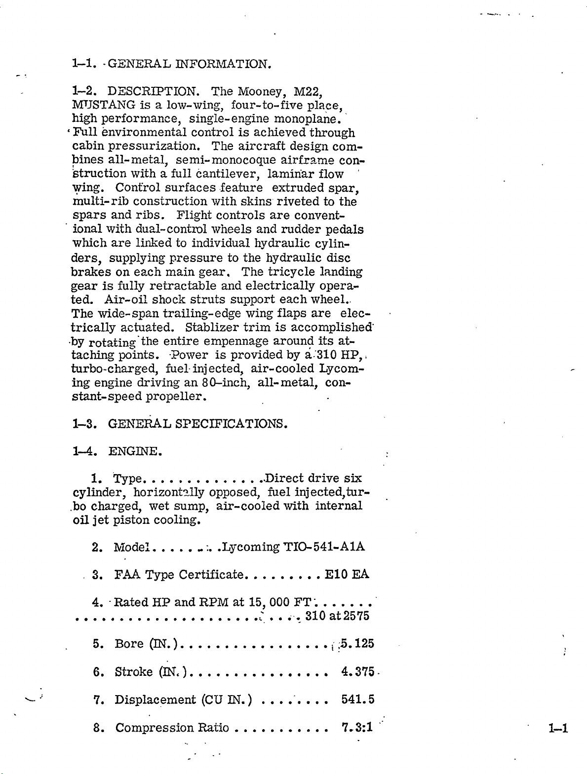
1-2,
MT3STANG
DESCRIPTION.
high
Full
environmental
cabin
~ines
’struction
wing.
multi-rib
spars
ional
which
ders,
brakes
gear
ted.
The
trically
pressurization.
all-metal,
with
Control
construction
and
ribs.
with
duzl-cont~ol
lin~ed
are
supplying
each
on
is
fully
Air-oil
wide-span
actuated,
´•by
taching
points,
turbo-charged,
ing
engine
stant-speed
is
a
lo~y-wing,
a
surfaces
main
retractable
shock
trailing-edge
entire
Euelinjected,
driving
propeller.
The
four-to-five
single-en~ine
control
The
semi-monocoque
full
cantilever,
feature
with
Flight
to
pressure
Stablizer
´•Power
an
controls
wheels
individual
gear,
struts
empennage
is
80-inch,
to
and
support
provided
~ooney,
monoplane
is
achieved
aircraft
lamin‘ar
extruded
skins.
are
and
hydraulic
the
hydraulic
The
tricycle
electrically
wing
trim
around
air-cooled
all-metal,
M22,
place
through
design
airframe
flow
riveted
rudder
to
convent-
cylin-
landing
opera-
each
flaps
is
wheel..
are
accomplished’
its
a:310
by
Lycom-
com-
con-
spar,
the
pedals
disc
elec-
at-
BP,:
con-
1-3,
1-4.
1.
cylinder,
.bo
charged,
oil
jet
2.
3.
4.
5.
6.
GEjhTEItAL
ENGINE.
Type,,,,,...,,,.,
horizontc~lly
wet
piston
Model,..,.,
F,4A
Rated
Bore
Stroke
cooling.
Type
HP
~I.
Displacement
SPECIFICATIONS.
opposed,
sump,
Certificate.
and
air-cooled
RPM
(CU
.~coming
at
IN.
..Direct
fuel
,.,.....E10
000
15,
´•i:.
drive
injected,tur-
FT;
internal
310
at2575
with
TIO-541-AIA
i
:5,
six
EA
125
4.375-
541.
i
5
8.
Compression
Ratio
7,
3:1
I-1
9.
(LBS)
Standard
Dry
Weight,
wit’h
accessories
......570~
1-5
1-6,
PROPE
1.
Type..............
2.
Model
Diameter
3´•
4.
Low
5.
HighBladeAngle
Governor.
6.
7.
AIRFRAME
I.
st.
Clearance
Tip
Dimensions
Wing
LLER.
Blade
span
.Hartzell,’
~T.).,.........
Angle
to
(FT)
KC-CBPK-
~EG)
Ground
Constant
Single
(IN.
Speed
1B/8415-
c...80.
O-FOO
30’’20
acting
13.75
35.
4
0
0
b.
;c.
d,
2.
a.
b.
c.
d.
e.
f.
g.
Fuselage
Tail
Stabilizer
Areas:
´•Wing.
Ailerons
Flaps
Vertical
Rudder
Horizontal
Elevators
height
(SQ
(SQ
length
(FT)...........21.
(FT)..........:.,..
(SQ
FT)
FT)
(SQ
(FT).
FT)...........
18.
FT)8´•
span
(SQ
fin
FT)
Stabilizer
FT)
(SQ
0
tVane
2
(SQ
r
Dorsal
FT)
0
9.0.
11.
7
93
166.
5
11.
25
4.
25
Ili´•
Y~CO
6.9
5
21.
0
12.
3.
a.
REVISED
Wsights
Weight
04-.22-68
and
empty
t~oadings:
(I;BS)
2425,
I~L
c
b,
Gross
Weight
(LBS)
,,,,,,,,,,3080,
STA
;i
Useful
c,
d,
Wing
Power
e,
4.
Wings:
Airfoil
a.
Airfoil
b,
Mean
c,
93,
83i,,
icO
d..
Center-of-Gravity
Geometric
e.
Load
Loading
(LBS),,,,.,,,,,,.
(LBS/SQ
(LBE/HP).......
atWin~Root
atWing
Aerodynamic
Tip
I~wist
.....NACA
Modified
Chord
Range.....
~EG)..
FT)
10,
,,,,,,22,
NACA
(IN,
2~
63~-215
at
wing
Llf´•
-to
31~0
,1255,
.11.87
641-
,59,18
1030’
t
05
MAC
Incidence
f.
DihedralAngle
g;
h,
Aspect
i.
Taper
5,
Fuselage:
Cabin
a,
(1)
(2)
(3)
(4)
(5)
Ratio
Dimensions
Keight
Width
Length
Cabin
Cabin
An~;´•le
Ratio
(IN.
Door
Door
(DEPJ)~’$
(DEG)........,.50
..,.....,........1.
Width
Keight
(IN,
(~N.
29
i""’
i"
17,
35,
30(
30’
338
935
89.
42,
118
34;
Q;
b,
.......5.
(1)
Maximum
Pass.
4
-Paas.
Compartment:
Loading-r;E~‘
´•,Co~figuration...
-Configura-tidn
i´•...
1’00,
270,
1-3
(2)
Baggage
Space
(CU
FT),,,,,,,,25,
c,
(3)
(bL)
(5)
Eandin~
(1)
(2)
(3)
(4)
0)
(6)
Baggage
Baggage
I:at
Racl~
Gear:
Type........
Operation
Wheel
Wheel
Tire
Tire
Tire
Size-nose
Size-main
Pressure-nose
~oor
Door
Track
Base
VJicith
Heiirht
Capacity
.Tricycle
(FT),,,.,,,,,,,.
(FT)......,.,,,,8,
(6
(6-ply
(~N.
(I]i~.
(LFS)
ply
rating),,6,
rating),,6,
(PSI).......45
Retractable
Electrical
21,
10,
II,
OOxB
00x6
4
25
Tire
(8)
Strut
(9)
Strut
(10)
the
center.
Fuel
FL:el
Strut
Strut
axle
(II)
(12)
´•´•´•´•´•´•´•´•´•´•´•´•´•´•´•´•´•´•´•´•´•´•´•´•26´•40L1/8
6,
a.
Pressure-main
Pressur~-nose
Pressure-main
Extension,
Extension,
Strut
(St’atic
and
Oil:
Capacity
extension
center
with
(r;sable
(PSI)
:ERtended
Extended
,,,,,,42
(PSI~
(PW)..
´•´•´•´•´•´•´•´•´•´•´•´•135.
measured
attaching
fuel.
U.S.
Static
43
Static
gallons).,
"1/8
from
Nose,
,,,,,25,
Main,
is
to
the
full
80´•
bar
92
b,
grade)
c,
d.
REVISED
r~el
Oil
Capacity
Minimum
11-15-67
Octane
(G~T)..............
Safe
Oil
Quantiijr
t~vel
aviation
(QT).,
.5~4.
4,
-1-4
I-?.
has
ENGINE
two
panel,
cam-locks
-ing
upward
maintenance.
tain-two
control
rods.
pull
fore
plete
flaps
top
ring
skin,
cess
the
the
cowling
the
are
just
cowling
to
ring
through
baffles
Cooling
the
sf
the
lower
able
cowl
required
varying
full-open
cylinder
at
all
times.
engine
ly.
COWLJNG.
side
cowl
side
The
at.the
to
cowl
torque-arms
These
side
and
engine
installed
forward
can
the
top
cowl
cylinder
insure
air
also
engine
cowl
flaps
cylinder
fight
for
doors
cowl
doors
front,
provide
The
flaps
cowl
lower
cowling.
be
of
opening
cooling
access
side
connected
by
rods
doors
in.the
of
the
removed
the
engine.
and
adequate
enters
compartrrieni,
flap
openings.
dllow
conditions.
ground
the
head
operations,
fiinged
bottom,
cowl
quick-disconnect,
must
can
nose
Two
lower
firewall.
is
fins.
cooling
the
pilot
temperatures
Open
head’temperatures´•closely~
must
shutdown
Cowl
flaps
to
dissipate
The
engine
to
fastened
are
and
to
the´•engine-for
doors
the
to
be
disconnected
be
raised.
section
additional
nose
in
one
Ram
forced
Tightly
for
accessory
and
is
’I’he
to
maintain
cowl
and
be
residu~il
cowling
the
top
rear,
each
cowl
skin
section
The
piece
air
enters
downward
sealed
the
engine.
section
exhausted
six
adjust-..
under
flaps
monitor
full-open
heat
cowl
with
open-
con-
flap
push-
be-
A
n~se-
com-
cowl
complete
for
ac-
through
the
at
even-
1-8.
cally
steerable
LAND7NG
operated
air-oilstruts,
nose
gear
nacelle,
into
the
wing.
spring-loaded
landing
down
traction
Safety
break
gear
by
switches,
the
cidental-gear
The
landing
position
retraction
cronized
extension:
REVISED
nose
retracts
while
control
bungee
mechanism
gear
retraction
gear
wheel
by
linkage.
r$close’the
to
Gear
11;-15-61
GEAR
tricycle
wheel,
and
hydraulic
aft
the
main
main
The
mechanical
springs
in
acGtauted
actuator
is
well
Nose
position
SYSTER~.
landing
a
shimmy
into
gear
lever.
which
an
circuit
on
doors,
nose
indicator
disc
the
retracts
gear
locks
The
overcenter
strut
by
the
enclosed
gear
~heel
.The
gear
dampener,
brakes.
lower
held
is
linked
gear
preload
compression,
to
prevent
ground.
in
actuated
door~
doors
lighas
electri-
has
engine
inboard
up
to
is
the
position.
the
by
are
are
a
the
held
up
gear
syn-
upon
re-
ac~
The
by
pro-
I-E
vided
warning
has
mit
15
on
3N.
manual
st
manual
horn
HOvith
electrical
dlectrically
not
Do
retract
the
instrument
sounds
override
lowering
malfunction,
while
the
the
landing
the
ge’ar
panel.
when
on
the
of
Do
manual
manually.
the
the
gear
gear
not
A
throttle
up.
gear
in
operate
override
gear-throttle
is
reduced
The
systenl
actuator
the
event
the
is
engag~ed.
to
of
gear:
to
per-
an
1-9,
steerable
by
engaged
~pedals
cam
wheel
to
nose
limits.
1-10.
are
are
rudder
pedals
provide
Shuttle
NOSE
a
push-pull.
centers
well.
right
gear
stalled
installed
individually
upon
for
and
A
BRAKE
pedals.
are
hydraulic
valves
automatically
brake
pedals
control,
panel,
tains
craft
´•-the
lated
The
operates
pressure
is
parked.
brakes.
slush
parking
parking;
and
overnight
servoir
of
the
is
firewall.
GEAR
nose
rudder
left
can
hydraulic
standard
as
linked
located
and
brake
use
located
linked
gear
tube
gear
the
The
is
which
retraction,
control
nose
nose
of
center.
is
only
wheel
wheel
..-´•rIwhentowingthe
be
da!naged
if
shimmy
equipment.
SYSTEM.
on´•each
controlled
Both
switch
when
are
on
a
on
~Lse
water
wheel
parking.
to
hydraulic
pressure
either
depressed.
the
parking
the
Do
not
overheated,
is
chocks
in
the
Hydraulic
main
by
the
pilot
brake
the
pilot’s
brake
brake
set
could
designed
for
The
nose
landing
SYSTEM.
to
the
rudder
automatically
freeing
during
upon
Observe
will
entry
easter
turn
aircrajPc,
turned
dampener‘l:s
toe
and
cylinders
to
operate
hydraulic
pilot
The
lower
discs
parking
freeze
for
mooring
hydraulic-fluid
wheel
beyond
gear.
pressure
co-pilot
or
parking
valve
while
when
or
the
short-duration
The
the
flight.
into
18
limits
in-
brakes
dise
which
the
pressure
co-pilot
instrument
which
the
brakes
brakes.
well
forward
pedals
dis-
rudder
The
the
degrees
asthe
its
Brakes
on
rudder
brakes.
brake
m~ain-
air-
when
accur~u-
re-
the
the
control
pilot
arril
control
flight
the
conventional
tubes
to
FLIG~‘IT
or
bell
CONTR~r)L
system
co-pilot
in
operation,
cranks
wheels
can
seat.
and
SYSTEM.
be.operated
All
utilizing
to
link
rudder
flight
the
from
controls
push-pull
control
pedals~
The
dual
either
are
surfaces
1-f;
rudder
i
inter’connectbtrngee
linked
are
mechanism
controlled
’~laps
panel,
are
m’nich
A~ongitudinal
-’~perated
rotating
wheel
POS~TnTE
Positive
two-~uris,
senses
the
meters
units.
and
control
element.
all
little
or
is
Control
P.Ci’system.
system
trim
differential
1-12.
Mooney
equipment.
erated,’
that
from
is
superimposed
consists
and
which
servo
rudder
and
Positive
landing
pilot’s
pneumatic
sense
lieves
inoperative.
with
craft
an
by
assist
to
operates
trim
the
set
to
appenna~rre
pneum~tically
androtary~valve
bei~veen
CONTROL
Control
The
system
both
roll
engine-driven
on
of
a
gyro
vacuum
The
bell
cra~s
operates
is
wheel.
relay,
which
Depressing
servo
effort
vacuum
The
~nd
P,ilerg~n
control
in
smitch
a
by
areversible
is
manually
stduilier
principal.
operated
rudder
system
is
automatic-control
and
y~ur.
vacuum
manual
the
sense
pressure
to
The
are
provide
from
servos
supplies
and
system
can
with
and
spring
coordination,
the
on
angle
The
instl-ument
electric
attach
of
directional
means
by
controling
trim
SYSTEM,
a
pneumatically-op-
element
a
button
the
renders
no
servo~.
standa-rd
is
Power
pump.
flight
to
cylinder-pis’ton
lirLited
dual
a
t~eoff
cutoff
operates
vacuum
cutoff
be
overpowerec~
damage
mechanism
is
The
control
(rate
to
button
button.
the
to
systems
motor.
vacuum
der:ived
sSlstena
g3rro~
the
ai:l~ron
system.
throu6,rh
orr
a
the
to
sys’tcm
the
The
the
by
of
system
the.
~ro
re-
alr-
trim
a
1-13.
power
hour
storage
partment,
voltage
warning
panel
1-1~.
turns
sealed,
inboard
the
rear
vent
These
to
pump
downward
prevent
in
ELECTRXC
is
supplied
iLLLt=lllaLVJ.
The
re~ulator,
light.
power
FUEL
integral
section
out5oard
vents
freezing,
each
battery
system
A
Sk’STENI.
W:nba
of
through
designed
are
tanl;
POWER
a
by
d~lLI
located
z?
overvoltage
battery
and
on
tar;ks
each
corner
A
provides
SUPPLY.
12-volt,
o
/C)Tlnl´•C
IL1’
L~
in
a
switch
off.
The
trarLsistorized
fuel
haS
located
wing.
of
lower
the
a
as
submerged
positive
?O-AMP,
YV
the
engine
relay,
on
system
Tznir
each
wing
Electric
35
ampere-
the
overhead.
the
in
vents
tanir,
electric
fue~flow
self-
com-
and,c;t
has
for´•´•c~rard,
in
arc~
an.d
surfa;:e.
boost
and
1-’
takeoff
of
Tank
fuel
the
the
tank;
lowest
on
fuel
the
selector
fuel
right
drains
ends
pumplic,
engine
boost
An
the
point
of
gages
The
the
emergency
right
rear
pump
electric
section
supplements
i
".landing.
the
.:i
bottom
compartment.
actuation
is
and
the
bjr
driven
the
engine
stalled
selector
fuel
system.
cated
tank,
fuel
console.
is
energized
emergency
fuel
pump
crankcase.
at
lowest
valve
the
at
and
are
controlled
by
point
drain
Fuel
inboard
wired
a
fuel
is
mounted
quantity
and
to
is
by
switch
pump
Fuel
in
at
outboard
fuel
the
in
switch.
on
sump
each
the
transmitters
quantity
pump
valve
panel
engine-
rear
are
fuel
in
are
each
on
and
in
and
of
in-
the
lo-
the.
1-15.
mounted
on
wires.
Engine
-pane’l
vides
The
each
winds.
sure
instrumentation
ment
manual
mental
pilot’s
valve
’panel´•for
1-16.
INSTRUMENTS.
tracks
The
instruments
as
air
static
side
This
for
panel
and
control
lower
is
CABTN
on
for
is
pressure
of
operation
located
’E~mergency
VENTILATING
Pressurization.
achieved
charging
by
system.
turbocharger
cabin
pressurization
exchanger,
components.
operational
an
rated
differential
airflow
have
percent
pressure
and
Pressurization
trols
pressure-dump
the
easy
flight
the
system
the
system
lighting
automatic
panel.
pilot’s
acceleroineter.
fuselage-to
using
instruments
panel,
access
panel
are
to
operate
uses
supplies
of
the
static
equipment
dimming
An,dlternate
behin~d’the
operation
PRESSURIZATION,
SYSTEMS.
land
air-flow
The
power
power,
of
is
set.
and
cp
bleed
The
its
system
five
entirely
shutoff
system
controls)
duct
settings
while
of
to
Pilot
using
and
with
been
All
to
is
fully
installed
two
altimeter
Cabin
air
system,
and
is
4.
1
Seven
automatic
operated
valves
shock
the
instruments
slides
the
on
The
yjitot
airspeed
buttons-one
mounted.
flight
which
instrument
static
compensate
atmospheric
and
other
pressure.
incorporates
systems.
located
are
static
pilot’s
instrument"e
’of’i6struments;´•´•i
HEATING,
pressurization
from
pressure
designed
maintaining
PSIup
the
turbo-
is
composed
the
on
as
pouirj~er
engine,
ram-air
a
control
to
low
to
24,
once
emergency
are
provided.
a.s
are
outward
lines
and
co-pilot’s
System
indicator.
on
for
cross-
pres-
The
instru-
both
Environ-
the
on
pre~sure‘?’
AND
is
of
the
the
heat
be
fully
25
cabin
a
000
feet
minGte.
the
con-
pro-
:i’
1-8
-WAR~TING
The
pressure
the
aft
defective
2.
Heating.
may
do
set;
A
obtained
tb´•
reduce
which
maximum
temperature
through
changer.
ation
the
ambient
cabin.
manifold
Hot
ing
ambient
heat
air
side
duct,
A
from
ventilating
circulates
tributing
heating
3.
head
is
airscoop
unpressurized.
4.
Defrosting.
frosting
duct
windshield.
When
system
dividual
1-11.
it
through
to
ring
to
open
cabin
throuph
(below
the
cabin
entry!
pressure
not
i;ari~per
valve
through
the
temperature
reach
engine
controlled
is
the
conditioning
A
shutoff
in
conSunction
exchanger
or
turbo-’charger-
heater
provides
the
the
to
heat
corltrol
of
air
blower
cabin
system
or
cooling
Ventilation.
provides
obtained
is
through
defrosting
EMERGENCY
is
impossible
the
baggage~compartment
release
the
door.
the
outer
the
door
regulating
bulkhead
with
must
Cabin
the
ram-air
a
temperature
loads
valve
duct,
muff
a
muff
source
surrounding
is
exchanger
cabin
in
the
air
through
to
provide
air.
A
Heated
from
a
nozzies
the
locking
Tb
baggage
handle)
nor
the.bagga=e
or
any
valves
c~8
these
be
replaced.
air
temperature
heat
the
of
20,
by
side
in
with
allows
bleed
sent
000
varying
of
the
a
of
au~ilary
through
and
at
temperature.
aft
end
the
even
manually
ventilation
air,
the
cabiii
control
at
EXIT
to
OR
open
pins
~gain
emergency’
do’or,.’i~ress
and
t;;rn
windoui’which
located
f~36t(lr’Y
valves.
control
exchanger
turbonbleed
200’F
of
feet.
the
cabin
free-
selection
airflow
of
overhead
distr8bution
operated
for
valve
the
ENTRANCE.
the
and
door
Cabin
air
heat
pressuriz-
air
the
right
cabin
the
mixed
the
cabin
when
windshield
pre~ssurization
~ind
~base
cabin
door.
turn
entranc’i~
handl’e‘.
the
can’be’opened
will
on
under
flow
ex-
valve
of
to
the
condition-
with
A
dis-
over-
the
ducts´•to
of
each
door,
Pull
the
the
provide
is
used
air,
air
in
either
exhaust
heat.
re-
of
cabin
de-
exit
the
handle
~o
thU~1Sd
If
in-
the
release
neither
break
exit
or
1~9
SECTION
GROUND
SERVICING,
INSPECTION
HANDLING,
AND
´•_.´•_
SECTION
.___
U,
GROUND
HANDI;~G,
._´•
_´•
_I
SERVIC~O,
r´•
AND
I
PARA
2-1.
22´•
2-3.
2-4,
2-5,
2-6,
2-7,
28,
2-9.
2-10,
2-11,
2-12,
2´•13´•
214´•
215;
2-16,’
2-17,
218.´•
2-19.
2-20..
221,
2-22,
2~23.
2T24,
2-25.
2-26,
2-27.
2;-28.
2-29,
2-30.
231.
2-32.
2-33,
2-34,
2-35,
Ground
Towing
Warmup
Parking
Emergency
/General
Fuel
Fuel
Fuel
Servicing
Sump
SeZector
Defueling
Engine
Engine
Battery
Tires
Hydraulic
Brake
Nose
Nose
Main
Servicing
Gear
Gear
Gear
Oxygen
Oxygen
Cleaning
Windshields,
Engine
Interior
Jacking.
Leveling
Weight
_
Outdoor
Longtime
Returning
Inspection
Check
Aircraft
PolnLs
Engine
TABLE
OF
randling
and
Taxing
and
Mooring
Procedures
Air6raft
Drains
Oil
Induction
Brake
Shock
Servicing
Valve
Air
Reservoir
and
Strut.
Steering
Shock
Struts
System.
Fac"e
Masks
Windows,
Compartment.
and
Upholstery
and
Balance.
Storage
Storage
Plircraft
File
Inspection
Functional
CONTENTS
Drain
Filter
Bleeding
Shimmy
to
Service
Check
and
Damp
Boors.
I
..,.,.,,21
,..,...2-4
........21.
......,...28´•
........2-11
.........2-13,
.,......2-14~
.,.,...2-41.
..,,2-3
PAGI
21
..21?
2-1
2-1
2-2,
23
23
2-4.
25,
2-6,
28
29´•
29
210
210
210
2-11
~12
2-12
212
21L~
2-17.
Z1P.
2-
1’9
2-i9
2-t0.
~d-
z
rC
;TION
II.
GROUND
HANDLING,
TABLE
(Continued)
SERVICn;IG,
CONTENTQ
OF
AND
INSPECTIOW
PARA
i-36
2-37
2-38
2-39
2-40
2-41
2-42
2-43
2-44.
2-45
2-46
2-47
2-48
2-49
2-50
2-5~
2-52´•
25-Hour
fj0-Hour
100-Hour
Scope
Engine
Inspection........´•
Inspection.
lOeHour
of
Inspection.......´•´•
Propeller
Landing
Fuel
AircraftExterior
Internal
Special
AircraftInterior
Flight
Instrument
Cabin
Electrical
Post
Gear
Sjrstem
Aircraft
1000-Hour
Control
Pressurization
Inspection
Inspection
periodic)
(or
Inspection.........´•´•´•´•´•´•
Retraction’System
Inspection
Inspection
Inspection.......´•´•
Inspection......´•´•´•
Inspection......´•´•´•
Inspection.........
Ins9ection
Leakage
Functional
Flight
Test...........´•´•´•
Test
Inspection...
Inspection
Test
PAGE
21
2-
2-22
2-23
2-23
2’
2-25]
2-26)
2-20’;
2-27
2-28!
2-28
2-28~
2-20j
2-30
2-32
2-
24
32
.,I
REVISEI/
’-.´•:j-5
2-1.
C~OUhTD
KA~DLING.
2-2.
:ai~craft
iing
TOW~G.
in
.hangar.
taches
aircraft
t~he
~tLtively
When
iin
hand
wings,
board
peller
equipment
CAUTION:
the
the
of
result
no
moving
is
aircraft
nose
180
portion
either
by
close
to
the
smooth
towbar
the
permited:
on
(2)
hub.
is
When
wheel
if
this
Use
hand
and
quarters
nose
providing
and
is
aircraft
the
of
propeller
Towing
not
recommended,
maneuvering
exercise
past
side
turning
a
for
on
wheel
the
the
available,
is
on
(1)
wing
tips,
by
caution
normal
its
of
center.
angle
towbar
ateerin~
the
axle.
ground
tires
r~quired,
the
blades
tractor
is
for
ramp
The
One
surface
are
properly
when
or
leading
and
(3)
or
or
not
to
swivel
Damage
exceeded.
moving
and
maneuver-
in
or
towbar
man
assistance
pushing
edges
on
adjacent
other
towing
turn
angle
will
the
a
at-
can
move
is
re-
inflated.
by
of
the
in-
to
pro-
powere~d’
2-3.
who
WARMUP
service
checked
personnel
aircraft.
Start
1.
Manual).
2.
Taxi
their
test
3,
While
nose
turn
reaction
sponse
2-4.
the
and
the
gear
4.
Check
coordinator
5.
Check
6.
Check
PtlRKL~G
aircraft,
aft
parking
out
by
before
and
forward
effectivness.
steering.
during
to
engine
of
main
brakes
AND
and
handle
qualified
attempting
warmup
taxing,
operation
during
operation
turns.
engine
control
AND
install
wheels.
TAXDI~G.
the
pilots
few
a
make
of
turns.
of
instruments
wheel
be´•
may
c~ircraft
or
to
engine
feet
and
shallow
gyro
PC
System
movements.
chocks
For
short-duration
used.
Ground
should
other
warmup
~2efer
check
turns
instruments
for
sluggish
When
for
personnel
be
responsible
taxi
or
to
Owners
brakes
to
test
for
control
parking
the
to
and
re-
parking,
,-I

_:,´•
’wheel.
three
side
outboard
’tensil
.~hor
tiedown
ring
either
nose
belt
snug.
craft.
NOTE:
brakes
and
ing
when
i.
moor
a.
b.
c.
of
d.
to
e.
and
f.
gear
g.
2.
Do
&re
slush
cold
aircraft
MOORING.
the
Read
Place
Drive
feet
outboard
the
tailskid.
Install
of
strength
ground
rope.
Tie
the
anchor
side
For
and
Lock
through
For
not
overheated
acculuulation
weather.
airplane
aircraft
chocks
stakes
tiedown
each
rope
stake.
center
rope
of
tail.
additional
anchor
controls
the
maximum
set
tied
is
When
as
i~nto
fore
in’ground,
of
main
to
of
ends
control
protection,
parking
or
could
Do
not
down.
parking
follows:
the
anc!
each
rings
gear.
each
Allow
a
rope
to
security,
to
a
ground
by
looping
wheel
brakes
wl;en
freeze
set
parking
outof
wind.
aft
approximately
main
in
the
Tie
tiedown
little
a
to
ground
attach
right
when
moisture
doors,
of
each
gear
and
and
wing
a
GG~3-pound
ring
slack
tail
skid
stakes
a
stake.
seat´•
drawing
hangar
ciur-
brakes
ma;,n
to
either
receptacles
!min.)
and:
an-
in
each
tiedown
at
the
to
safety
the
air-
rope
the
belt
2-5.
of
EMERGENCY
i.
Engine
fire
a
starting,
take
ing,
Close
a.
Turn
b.
Set
c.
Turn
d.
Pull
e.
f.
Discharge
compartment
2.
Fuselage
fire
in
wheel
’immediateljr
controls
the
aircraft
REVISED
in
the
if
the
inixture
firewall
in
the
to
04-22-68
Fire
During
engine
the
fire
following
c’owl
.9ll~switches
’flaps.
control
fuel
well
place,a’il
selector
fire
through
or
(or
OFr"
extinguish
Wheel
PROCEDURES.
Starting.
compartment
is
not
.put
action:
´•off.
at
to
OFF
shutoff
valve
extinguisher
the
nose
Well
in
the
cabin
electrical,
position;.
the
flames.
IDLE
cowl
Fire.
then,
In
during
out
by
CUTOFF.
to
OFF.
into
openings.
In
fuselaEEe
or
fuel,
the
the
and
engine
cranlr-
case
event
engine
of
;ti-ea),
ig;lition
22
k
3.
(exccpt
ed
by
that
automatically
overload
an
df
an
the
aflit
Electrical
the
circuit
electrical
alternator
Make
for
Fire.
ignition-starter
breakers
interrupt
short
or
sure
electrical
fire,
circuit
turn
iield
that
electrical
All
circuits)
(orcircuit-breaker
of
flow
battery
extin,ruisher,
used.
off
switch
only
fires,
the
occurs.
the
immediately.
fire
a
is
circuits
are
In
protect-
power
the
switch
switches)
when
event
requirements
~ig
,´•~ubrication
r
$ervicing
meet
I~
conditions.
ing
environmental
perature
humidity
high
facilities,
shorten
27.
through
tank
has
capacity
filled
~half
lation
30-gallon
be
may
GENE,stAL
intervals
avera~e
ranges,
or
service
FUEL
filler
a
capacity
is
to
of
moisture
indicator
viewed
AIRCRAFT
are
Guide
requirements
When
conditions,
dusty
and
unusual
and
SERVICING.
ports
95’1J.S,
minimize
through
outl!:r?ed
Fi~ure
considered
are
operating
atmospheric
moisture,
operating
maintenance
on
top
of
47
gallons.
condensation
within
installed
is
the
SERVICING.
in
under
such
unimproved
Fuel
of
the
U.S.
gallons:
Keep
the
tartls.
filler
the
Service
These
adequate
normaJ.
under
as
abnormal
extreme
conditions,
airport
requirements,
intervals.
tanks
wings.
fuel
in
each
opening.
A
are
and
serviced
Each
total
tanks
accumu-
visual
tank
Servic-
and
to
operat-
tem-
fuel
at
and
least
vehicle
ing
WITHDI~
NOTE:
mosphere
vent
surface,.
each
Z-8.
valve
tank
to
Drain
’REVISED
nozzle
openings
flight.
FUEL
locared
is
provide
fuel
must
to
FEET
50
Each
at
C~heck
SUMP
for
sumps
11-15-61
The
be
wing
fuel
its
are
in
aircraft
grounded.
and
aircraft
of
tank
outboard
located
vents
GRAINS.
aft
the,
drainage
the
fuel
and
Ground
allow
is
for
inboard
NO
or
vented
rear
corner;
the
on
obsti´•uction~before
A
flush
corner
of
moisture
small
plastic
service
servic-
SMOKING
ve‘nicle.
the
to
lower
fuel-
~t-
wing
drain
of
and
cup
i
each
sediment.
23
furnished
tank
the
first
service.
and
with
selector
flight
of
the
valve
each
loose
equipment.
sumps
and
day
before
after
Drain
each
wing
fuel
NOTE:
fuel,
and
checking
fuel
29.
fuel
selector
fuel
system,
control
a
drain
1.
fuel
pull
2.
fuel
pull
3.
control
not
leaking
NOTE:
~requently
for
wait
sediment
selector
FUEL
the
Switch
drain
Switch
drain
After
knob
ice
After
at
both
SELECTOR
valve
and
the
on
fuel
draining,
is
outside
During
formation.
servicing
least
to
the
valve
has
fuel
selector
fuel
selector
valve
fuel
selector
control
full
cold
check’the
five
settle
fuel
drain.
at
is
a
console
control
for
be
forward
the
minutes
before
tank
VALVE
the
drain
valve:
sure
aircraft.
weather
fuel
the
lowest
valve
for
valve
10
and
a~rcraft
draining
sumps
DRAIN.
valve
fn
the
10
seconds.
fuel
that
operation,
selector
for
and
point
operated
cabin.
L
to
seconds,
R
to
drain
the
with
moisture
the
in
tank
tank
valve
drain
i
and
The
the
by
To
and
and
valve
is
210.
ed
boost
through
rmARNING
container
Allow
WITTHIN
boost
electric
to
and
by
i.
a.
b.
reach
c.
remove
d.
DE
FUE
pumping
pumps
the
hTO
50
defuel
To
pumps:
Disconnect
boost
Connect
fuel
Turn
Turn
fle’peat’.lsteps
LING.
fuel
or
by
filler
Ground
during
SM~KING
FEET
pump.
recepticle.
fuel
filler
boost
on
and
c
The
out
of
siphoning~fuel
ports.
aircraft
the
all
defueling
OR
OPEN
of
the
the
aircraft
fuel
line
flexible
a
selector
from
cap
pumps
dto
drain
fuel
tanks
the
tanks
operations.
FLAME
defueline;
by
at
output
line
of
valve
filler
until
other
may
with
from
and
the
area.
operating
fitting
suitable
to
desired
port.
tank
tanhr
the
is
be
the
tanks
fuel
the
length
empty.
drain-
electric
of
tank
2-4
L~-
---I---
To
2.
sump
stops
2-11.
oils
drains
running,
ENGINE
that
straight
CAUTION:
mineral
or
specification
in
Lycoming
the
is
responsibility
ufacturer.
1014
Oatest
I.
Oil
operation.
engines
first
the
sumption
Recommendations
2.
PnainP
nn
II-
for
oil
oil
engine
switch
several
should
is
to
afterthe
changing
compounded
steps:
Do
a.
oil.
clean
five
sludge
element
sume
ditions
Drain
b.
hours
c.
screen,
Do
or
normal
completely
and
fuel
OIL.
appear
mineral
Any
superior
oil
lubrication
compounded,
No,
engines.
Consult
revision)
Recommendations
Operate
on
straight
50
hours
has
stabilized,
hPPn
hnn
’’"U
UYY--
hundred
undertaken
be
in
an
extremely
additive
en~ine
from
not
oil,
the
has
straight
take
mur
straight
change
not
operate
before
Check
all
plugging.
every
10
oil
impi~ove.
and
301E
of
Lycoming
new~,
of
operation,
VrY-
oil
been
additive
the
oil
hours
drain
drain
fuel
selector
There
in
their
oil,
must
to
be
Proof
the
lubricating
for
oil
or
For
LIIIILP
hours,
with
di~ty
should
overhauled.
mineral
the
following
oil
mineral
filtelaand
the
engine
first
screens
Change
oil
if
sludge
periods
system,
drain
are
performance
use
conform
acceptable
of
Service
recommendations.
aviation
either
such
until
is
recommended.
straight
with
for
conformity
oil
Instru~tion
Elor’P~w-engine
mineral
or
ctraiahf
YI-
a
change
overhauled
oil
until
Oil.
If
netjvly
Changing
nn
V1I
caution.
condition,
deferred
be
When
oil
ar~d
replace
change.
for
oil
ar~l2
after
oil
additive
to
precautionary
straight
from
longer
evidence
filter
oil
is
evident.
sludge
opel´•ate
fuel
additive
to
Lycoming
use
man-
uuring
oil
con-
When
minprnl
to
additive
the
the
until
mineral
the
oil.
than
of
con-
LSI
or
engine,
Re-
Zt
CILUTI~N:
"compounded"
to
Do.
to
which
refer
cylinder
which
not
Do
refer
to
oils
to
improve
not
do
"top
as
remover"
oil.
engine.
cumstances.
The
a
them
use
used
class
certain
to
not
Such
terms
in
of
for
such
lubricanij’
are
such
use
oils
"detergent:’
manual
this
aviation
substances
aircraft
materials
cn&ine
use.
commonly
"dopes"
sonetimes
prnducts--they
automotive
can
oil
cause
"additive,
are
have
These
and
added
under
engine
intended
lubricating
"carbon
to
added
terms
known
fuel
been
damage-the
any
failure.
and
or
cir-
fJ.
engine
stopped
sump.
quarts..
door
the
4.
instdlled
is
refill
and
every
months
cumulated.
5.
-filterat
filter
-the
oil
suctioniscr’eenp,i31ean
;Examine
NOTE:
ation
when
with
and
,when.conditions
Checking
level
oil
long
Maintain
Access
the
in
Draining
in
sump
hours~of
50
if
50
Engine
the
right
cartridge
screeii’anrl
During
in
dusty
flights
prolonged
filter
~neine
after
enough
the
to
top
Oil
the
hours
Oil
have
element
Oil
for
engine
filler
the
cowling.
Sump.
oil
sump,
with
operation,
of
flying
Filter.
rear
of
each
at
filter
periods
areas,
been
idling
each
warrant.
oil
the
in
time,
Level.
the
to
oil
cap
A
quick-drain
Drain
the
correct
or
time
Remove
engine
oil
inspect
for
of
prolonged
cold
of
short
25
engine
drain
level´•
is
once
have
chdnge.’
metal
climates,
~ange
hours
Check
back
at
gained
the
every
the
and
and
!?articles.
duration
or
the
has
into
~31
to
through
fitting
oil
sump
grade
been
not
engine
replace
Remove
reinstall.~
oper-
or
oil
the
more-often
been
1´•B
of
four
the
oil
oil
I
ac-
the
d12.
ENCLNE
importaxlce
cannot
motes
be
fuel
dry-type
times
before
of
over
economy
filter
replacement
~NDUCTfON
f~eeping
the
emphasized.
and
can
usually
induction
longer
be
is
ATR
FILTER.
A
clean
engine
washed
necessary~
air
filter
life;
six
filter
to
The
clean´•.
pro-
The
eight
2-6
Replace
hours
first.
1.
2.
side
or
To
Remove
Direct
of
filter
the
at
clean
one
induction
year
induction
the
filter
jet
of
a
(opposite
filter
air
interva3s,
against
to
aircraft.
normal
from
air
whichever
air
every
filter;
the
air
500
down
flow).
occurs
or
clean
NOTE:
nozzle
a
3.
filter
4.
for
dam~e.
gasket.
NOTE:
of
carbon,
ing
5.
minutes;
to-five
deposits
NOTE:
recommended.
is
Keep
element.
After
steps
Soak
then,
minutes
Do
not
pressure
air
nozzle
Cover
cleaning,
Discard
If
the
soot,
5
through
fi3ter
~1Cate
to
Donaldson
use
greater
filter
or
in
nonsudsing
filter
free
Do
a
compressor
at
Icast
entire
inspect
a
ruptured
shows
oil,
8.
the
11-1400
not
than
area
filter
an
continue
back
filter
Filter
use
?Init.
100
t7;vo
inches
with
and
filter
accumulation
with
detergent
and
forth
element
Cleaner
solvents.
PSZ.
air
gasket
or
with
from
jet.
broken
clean-
for
for
of
15
two-
6.
water
bulb
or
8.
filter
replace
9.
airvalve
10.
proper
2-13.
distilled
plates
weather,
and
water.
gravity
1.
2.
quired.
Rinse
until
Dry
air
Inspect
before
filter
Check
in
Reinstall
sealing
BATTERY.
water
at
all
charge
to
Remove
Check
filter
rinse
filter
heated
for
a
light
with
flapper
wheel
and
times.
Keep
batter3r-box
electrolyte
element
water
is
thoroughly._
above
damage
bulb.
a.
new
vdlve
well
for
filter
in
security.
Service
to
maintain
After
battery
battery
freezirig.
with
cl~ar.
180~F
and
If
damage
one.
in
ram
proper
aircraft,
the
adding
long
above
cover.
and
service
stream
a
Do
not
for
ruptures
air
operation.
battery
electrolyte
water
enough
225
1.
use
drying
by
is
duct
making
using
to
specific
battery
of
clear
a
light
filter.
holding
evident,
and
sure
above
in
freezing
mix
electrolyte
as
of
only
re-
2´•7

3.
ed
electrolyte.
4.
st
use
water
Check
To
solution
to
neutralize
clean
battery
cables,
bicarbonate
of
box
terminals,
corrosion
for
corrosion;.
soda
of
and
spilled
and
and
Sattery
and
spill-
box,
clean
electrolyte.
CAUTION
bicarbonate
cells--permanent
Rinse
5.
6.
’S’i~i_ne
To
7.
petroleum
CAUTION:
ulator
system
when
Determine
load
214.
connecting
test
TIRES.
recommended
retard
jelly
are
only;
When
of
with
battery
after
The
designed
make
battery
least
~it
Keep
the
in
cleaning,
soda
to
damage
clean
water.
with
clear
corrosion,
cleaning
alternator
for
sure
a
charger
condition
twice
tires
the
Servicing´•and
enter
use
bf
each
coat
do
the
will
dry
terminals
and
tightening.
and
voltage
on
one-polarity
correct
booster
or
means
by
year.
at
the
Lubricatioa
allow
not
battery
result.
cloth.
polarity
airpressure
with
reg-
battery.
of
a
Guide,
2.
page
215.
Check
quently
a
hydraulic.
to
back~bleed
bleeder
cation
45
PSI.
CAUTION:
leased
servicing.
may
Check
Check
or
pulling.
HYDRAULIC
the
hydraulic.
for
proper
pressure
valves.
MILrO-
prior
be
under
tires
valve
the
5806.
Be
The
fluid
system
Use
sure
to
starting
high
for
stem
BRAKE
brake
~service
hydraulic
Pressui´•ize
fluid
pressure
wear,
for
reservoir
level.
through
parking
hydraulic
in
the
cuts,
evidence
RESERVOIR.
best
For
unit
~3ressure
the
fluid
service
brakes
wheel
due
to
and
bruises.
of
tire
fre-
results
wheel
(red)
unit
are
system
cylinders
expansion.
slip-
use
pot)
cylinder
specifi-
~at:
re-
28
2-~6.
Remove
i.
and
plug
into
line
2.
Immerse
fluid
unit
vdlve.
bubbles
shuttlevalve.
wheel
line
5,
install
container.
3.
to
4.
5.
6.
7.
and
8.
Attach
Depress
When
cylinder
Remove
BRAKE
install
filler
wheel
Depress
Feed
end
at
bleed
To
6.
filler
SERVIC~TG
hydraulic
suitable
hole.
open
pressurized
cylinder
the
fluid
of
into
flexible
co-pilot’s
Repeat
flow
is
bleeder
opposite
flexible
plug.
end
bleeder
pilot’s
system.
step
clear
fluid
fitting,
of
hydraulic
line
brake
of
valve
brake,
line
AND
flexible
brake
4.
air
from
BLEED~nTG.
reservoir
to
valve
pedal.
Check
immersed
pedal
bubbles,
and
remove
repeat
reservoir
attach
line
fluid
and
filler
flexible
in
service
open
for
air
in
to
reposition
close
service
steps
hydrai~lic
fluid.
4,
3,
and
re-
NOTE:
into
hole
9.
10.~
Resistance
are
depressed.
gear
flation
ton
over
shock
will
rough
servicing
NOTE:
strut
grit
the
pressure.
the
Check
Check
NOSE
and
not
piston
so
barrel
Hydraulic
system
brake
brake
must
GEAR
strut
extension
bottom
surfaces.
details.
Keep
not
as
with
fluid
through
lining
pedals
solid
be
SHOCK
shouldbe’checked
to
when
the
cut
to
may
the
for
for
when
insure
the
Refer
exposed
free
or
damage
resulting
be
reservoir
excessive
spongy
STRUT.
that
aircraft
to
paragraph
part
from
loss
gravity
brake
the
of
for
the
of
dust
fluid
feel.
pedals
The
proper
strut
is
the
seals
fed
filler
wear.
nose
taxied
shock
and
and
5-
pis-
~1
in
in-
for
i.
piston
Wipe
with
exposed
a
clean,
(polished)
cloth.
dry
area
of
shock
strut
29
tETdiii~TING:
Rsliova
ing
turns
~trut
2-18.
’DAMPER,.~
~iteering
through
Bhimmy
pydraulic
all
inch
3/4
counterclockwise
with
hydraulic~fluid.
NOSE
arm
the
damper
fluid
damping
Remove
pressure
(thin)
GEAR
The
are
hydraulic
level
action
~Lir
in
nut
on
before
STERRING
nose
connected
s~iimmy
should
checked
fails
to
valve
strut
air
gear
by
v-,ivo
to
removed
be
when
function
cap.
eurn-
2
servicing
SHIMMY
gr.
steering;
the
nose
damljer.
steering
properly.
1/4
bar
and
and
wheel
The
the
or
Check
inflation
landing
terrain.
details.
the
or
2-17.
2-20.
when
and
oxygen.
-the
the
bracket.
OXYGEN
fG.lly
1800
’Pn
snap-on.
co-pilot’s
Release
2.
Remove
3.
sembly
Refill
4.
oxygen
(Federdl
equivalent).
install
5.
mova!
procedure.
GEAR
main
and
when
Refer
(See
serviced
gear
extension
the
to
NOTE
SYSTEM.
PSIpressure,
refill
To
crain
LCVVVYY
~ULII
plastic
seat.
clamp
oxygen
cylinder
Specification
cylinder
SRUCK
shock
to
prevent
aircraft
paragraph
and
WAR~NING,
at
standard
contiains
the
oxygen
f~
nu~rapn
´•´•V
V1IJ
cover
securing
cylinder
with
in
STRUT~,
strut
taxied
is
5-11
The
oxygen
temperature
cylinder:
~vlinrlPr
VJ
bV1I
on
the-right
cylinder
and
aviator’s
BB-0-925,
reverse
piston
bottoming
over
for
servicing
paragraph
4.5cubic
just
re~ulator
breathing
sequence
_pbsition
un
rough
cylinder
(70bF)
feet
rpmn´•trp
J´•
UIIIV
forward
to
mounting
or
of
as-
re´•
for.
proper
of
of;
WAR~ING:
linder,
other
or
oxygen
oxygen
hazard.
do
not
lubricants
system
in
contact,
i
’Ci:hen
allow
components.
servicing;
oil,
to
come
creates
the
grease,
in
a
Oil
fire
oxygen
solvents,
contact
v~ith
or
cy-
with
pure
explosion
2r
2-/0
2-21.
face
When
the
masks
servicing
face
OX"ITGEN
masks
dition.
i~22.
?fdequate
CLEAN~G.
inspection
components;.
the
appearance
it
reduces
Before
i.
brake
cool
2.
3.
discs,
Flush
Wash
water.
are
the
pitot
away
with
FACE
stowed
oxygen
and
hoses
and
Not
only
of
an
probability
washin~
head,
loose
mild
a
I\liASKS.
with
system
to
Cleanliness
ru~mtenance
does
aircraft
of
aircraft
and
dirt
aircraft
Disposable
the
oxygen
include
determine
is
cleanliness
but,
corrosion.
exterior,
static
and
cylinder.
an
their
a
inust
of
most
ports.
mud.
detergent
oxygen
inspei~tion
oon-
9or
aircraft
enhance
important,
cover
and
~f
~md
4.
5.
pre-wax
6.
for
the
7.
edges
reduce
NOTE:
fluid
surfaces,
ing.
NOTE:
flushed
be
followed
aircraft
CAUTION:
household
exterior.
finish
skins
Use
To
remove
cleaner.
Apply
protection
Apply
of
wings,
drag
containing
treated
Do
detergents
Such
and
cause
soft
a
exterior-finish
an
a
heaty
empennage,
and
abrasion.
When
remove
Spilled
by
with
with
a
thorough
away
detergent
nait
detergents
corrosion
cleaning
heavy
of
acrylic
coating’of
fuel,
dye
at
battery
water,
bicarbonate
solution.
so
use
to
cloth
oxidation
enamel.
hydraulic
is
spilled
once
electrolyte
washing
wash
and
to
and
called
may
on
or
film,
wax
wax
nose
fluid,
on
prevent
the
of
soda
"mild’’
aircraft
the
damage
aluminum
chamois.
use
recommended
the
to
section
or
paihted
stain-
must
area
solution
with
mild
a
a
leading
to
other
be
must
NOTE:
~:leaners
period.
and
clean,
90
days
Do
during
Use
after
not
only
cool
apply
the
mild
water
delivery
wax
initial
or
paint
aircraft
during
or
repainting.
use
detergent:
pre-wax
curing
the
first
2-23.
Pressurized
doors
than
require
those
I.
shields
kind.
2.
hear
depth
prior
saturated
the
3.
require
4.
to
5.
-W~INDSiIIEL;DS,
aircraft
of
Prior
for
scratches,
Pay
especidll~
outer
Scratches
Flush
wiping.
Remove
with
more
hon~ressurized;
to
flight,
edges
installation
windshield
grease
kerosene.
stringent
which
Never
windshields,
inspection
air~raft,.
check
windows
cracks,
pane~
exceed
and
wipe
or
~ttentioli.´•
of
a
windows
with
oil
while
close
of
-4NDI)OORS.
windows,
fissures
or
010
0.
new
pane.
a
with
dry.
soft
and
to
inches
and
wind-
water
cloth
and
care
of
defects
in
any
CAUTION:
carbontetrac
tin~uisher
household
or
windows
soften
6.
static
7.
leakage.
8.
silicone’
9.
proper
2-24.
of
dirt
fire
a
spection
fluid,
or
or
craze
Clean
windows
plexiglas
Check
If
Check
operation,
ENGINE
and
hazard
door
seals
stick-type
cabin
oil
requirements.
Never
use
hloride,
de-icer
window
windshields.
the
surface.
and
cleaner.
seals
are
dry,
lubricant.
’and
COMPARTMENT.
within
and
the
hampers
gasoline,
acetone,
fluid,
cleaning
Such
windshields
for
damage
lubricate
~baQ;gage
engine
completion
benezene,
fire
ex-
lacquer
sprays
solvents
lightly
ddor
compartment
on
with
that
mechanism
An
accumulation
of
could
with
thinner,
will
an
a
vital
anti-
cause
for
creates
in-
NOTE’:
cowl.
1.
Wash
’compartment
2.
Wipe
pal´•tq~nt
2-25.
Use
dry
INTERIOR
normal
Consult
´•.opening
down
engine
using
engine
after
household
paragraph
instructions.
non-flamabl~
a
cowling
washing?
AND
3-2
cowling
and
arid
eng´•lne~com-
UPHOLSTTE,Y
cleaning
practi~tes.
for
engine
engine
solvent,
1
2-12
for
routine
i.
holstery
dust
and
2.
panels
a
With
~loth.
interior
Frequently
panels
dirt.
Clean
with
leather
mild
a
slightly
Remove
care.
vaccum-clean
headliners
and
aircraft
damp
grease
or
cloth
vinyl
and
spots
seats,
to
remove
upholstery
detergent.
with
dry
using’ajel~y
rugs,
surface
and
Wipe
a
soft
kick
spot
up-
clean
dry
lifter.
NOTE:
terior
solvents
NOTE:
for
vinyl;
be
can
dition
cleaners
NOTE:
ution
which
padding
of
carpets,
and
rub
to
remove
remain
CAUTION:
solvents
commercial
pounds,
tions
and
up
Never
furnishings.
which
Foam-type
leather,
used
the
to
entire
are
Never
could
materials.
keep
in
circles.
foam.
also
damp;
Do
interior
on
cleaning
follow
carefully.
the
area
apply
hai´•mful
are
shampoos
and
remove
interior.
recommended.
saturate
damage
foam
Do
dry
thoroughly,
not
use
manufacturer’s
the
Spillage
dried
furniture
IMost
plastic
stains
fabrics
To
minimize
as
dry
Use
a
not
allow
ali=ohol
plastics.
and
thoroughly.
polish
polishes
to
vinyl.
and
materidls
and
Sp;´•ay-on
with
the
backing
as
vacuum
carpets
or
When
finishing
should
to
contain
cleaners
to
con-
a
and
wetting
possible
cleaner
strong
using
com-
instruc-
be
cleaned
in-
sol-
to
L~
2-26.
aircraft
the
i.
holes
’the
nose
lage,
CAUTION:
be
on
to
jack
cinlrlp
the
structural
REVISED
~ACKTNG.
Install
outboard
jacir-pad
ten
inches
used
the
nose
install
point.
ia~lr
nose
0~-22-68
off
jack
of
The
to
obtain
jack
separate
nninf
or
using
damage.
the
aftof
Do
When
ground:
points
each
adapter
jack-pad
proper
points.
not
a
main
the
jacks
raise
~lcina
single
it
in
~zrewdll
is
necessary
the
gear,
adapter
weight
Do
under
tile
cPnarntP
YVr-I-U-V
jack
tie
beneath
not
nose
down
and
bulkhead.
must
distribution
s_ttelnpt
each
by
lacks
J
point
to
raise
mounting
i3osition
the
fuse-
nose
using
under
can
cause
a
21
2.
minimum
each
adapter.
to
contact
3.
j~evel
4.
liistzll
Raise
as
possible.
Secure
standard
42-inches
of
ack
j
Holdinl;
jack
aircraft,
safety
point
points
jack
aircraft
overall
and’
points
firmly.
keeping
locks
under
on
jacks,
extension,
the
nose
in
place,
wings
each
jack.
´•CX~7ith
5
raise
as
nearly
under
ack
a
pad
jacks
CAUTION:
out
of
10
I~IPI-I.
NOTE:
bleed
taneously
level
NOTE:
without
not
being
and
aft.
2-21.
aircraft
on
250.
the
LEVELING.
upper
Adjust
decreasing
by
raising
aircraft
boards,
Adjust
in
jack.
the
tire
@efert9
doors
When
off
pressure
ar,ci
it
as
is
The
raising
raised
determined
is
aircraft
air
or
laterally,
~orward
aircraft
on
Do
not
when
lowering
evenly
lowered.
nose.
the
skin
pressure
lowering
~lace
and
level
the
high
Figure
raise
the
wind
the
all
on
to
keep
wheel;
entire
should
Longitudindl
by
placing
line
between
level
in
the
a
center
side
the
velocity
aircraft
jacks
may
aircraft.
be
checked
the
jacks.
spirit
the
of
by
decreasing
or
by
aircraft
simul-
the
be
leveling
a
Station
I
by
nose
To
level
front
lowering
on
is
over
on
jacks,
aircraft
raised
Wheels
fore
of
spirit
level
225
increasing
wheel
level
the
on
seat
pressure
the
jacks
the
tire
the
floor-
tracks.
and
or
or
~28.
aircraft,
1.
listed
2.
3.
4.
of
each
5.
craft
6.
2-21.
WEIGHTAND
select
Check
the
in
Weight:
Ground
Drain
Position
of
the
Place
scales.
on
up
Level.
a
for
installation
aircraft
engine
a
three
a
ramp
aircraft
level
oil
2000
wheels.
BALANCE.
work
Balance
and
sump.
L~B
capacity
each
on
described
as
of
drain
area
dll
Record,
scale
Toweighthe
and:
equipment
fuel
tanks.
scale
and
move
in
paragraph
as
in
front
air-
2-14
 Loading...