

Mooney M20r, M20V, M20TN, M20U Service Bulletin

MOONEY INTERNATIONAL
CORPORATION
165 Al Mooney Road North
Kerrville, Texas 78028
THIS BULLETIN DOES NOT CHANGE AIRCRAFT TYPE DESIGN
SUBJECT: Mooney Aircraft Flight Control Balancing After Painting
MODELS/ SN M20R - S/N 29-0520 thru 29-0525
AFFECTED: M20TN - S/N 31-0128 thru 31-0143
M20U - S/N 32-0003
M20V - S/N 33-0004, 33-0006, 33-0007
TIME OF Before Next Flight
COMPLIANCE:
INTRODUCTION: Mooney International Corporation has determined a flight control balance issue may exist after
final paint by outside vendors. Mooney Engineering has determined that the aircraft listed will
need to have the specified control surfaces removed and balanced per Mooney specifications
found in the applicable Service and Maintenance Manual and Mooney Spec 20 Section 35. If
Rudder and/or Elevator Control Surface is found to be out of specification, you will need to use
STEPS 3.0 in this Service Bulletin. A Limitation Placard must be installed prior to flight for Aircraft
requiring flights to a maintenance facility. Compliance with this Service Bulletin will be considered
a one-time inspection and repair, requiring no additional inspections, unless flight control(s) are
repaired, replaced or repainted, which will then need to be rebalanced as required.
INSTRUCTIONS: Read entire procedures before beginning work.
SERVICE BULLETIN
SERVICE BULLETIN M20-335B
Date: January 2, 2019
NOTE:
All work to be done in accordance with FAA AC43.13.
NOTE:
Record ALL Surface Rigging Values before removing components. Run trim wheel up, all the way to the
stop before removing components.
- CAUTION -
DO NOT move control surfaces to extreme angles. Be gentle with tabs and do not bend them.
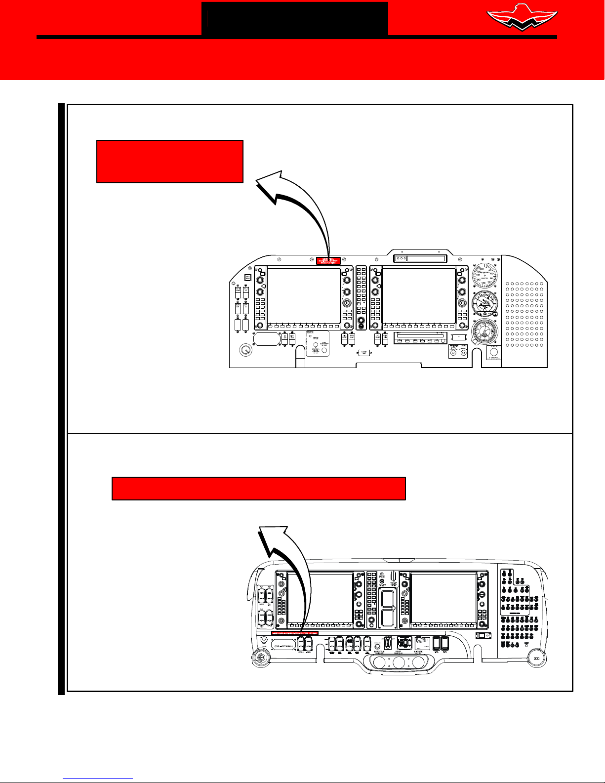
STEP 1 - LIMITATION Placard (for Aircraft requiring flights to a maintenance facility)
1.0 PLACARD INSTALLATION - Refer to Figure SBM20-335-1
1.1. Install placard P/N M20-335-901 or M20-335-902 on instrument panel, refer to Figure
SBM20-335-1 for effectivity, clean surface area with isopropyl alcohol before applying
placard, this will remove any oils or debris from surface.
1.2. Fly Aircraft to approved Mooney Repair Station for compliance with this Service Bulletin.
- CAUTION -
DO NOT EXCEED SPEEDS INDICATED ON INSTALLED PLACARD SBM20- 335- 901 OR SBM20-335-902.
STEP 2 - Checking Flight Control Balance - Rudder and Elevator Only
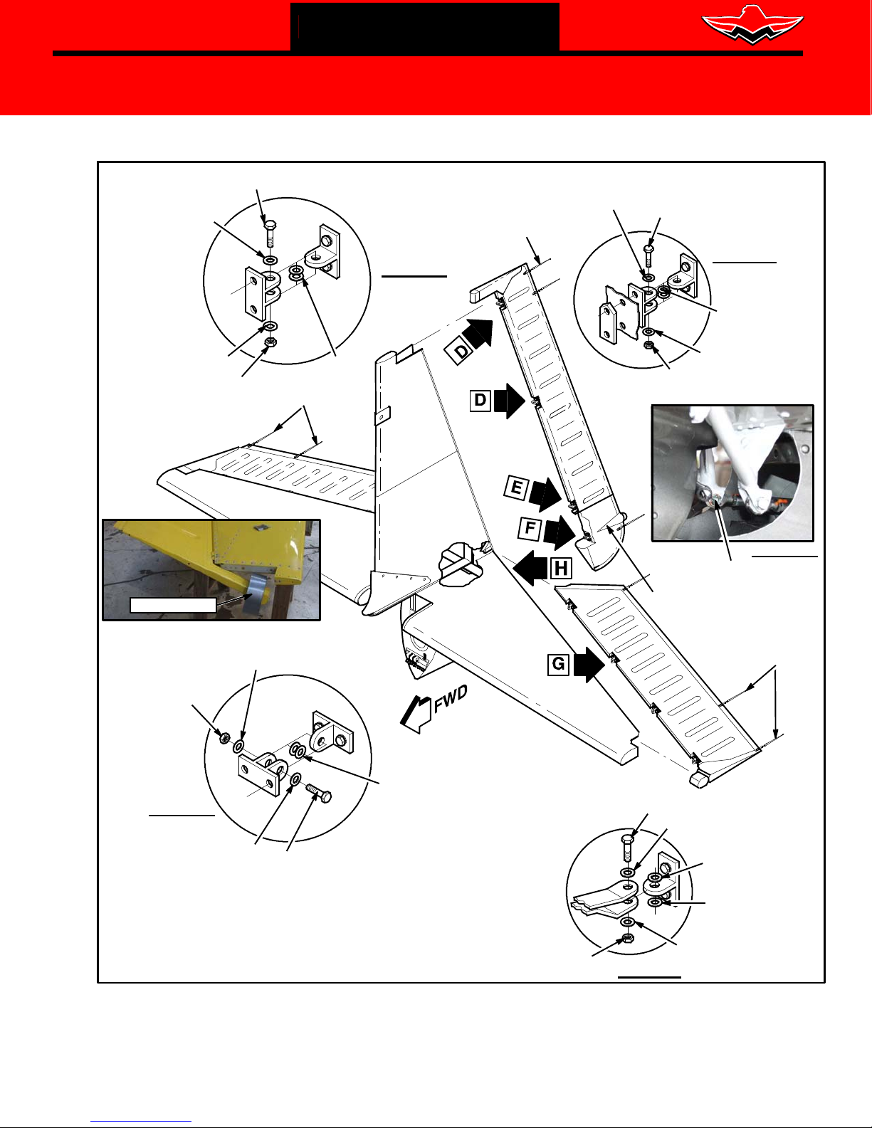
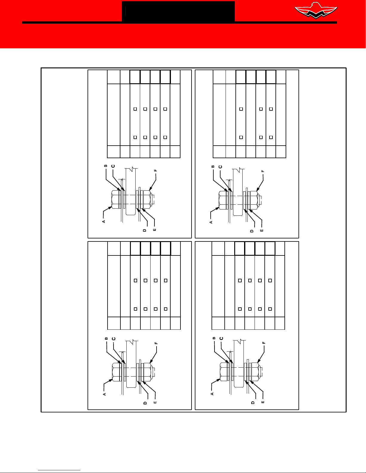
RUDDER REMOVAL/INSTALLATION - Refer to Figure SIM20-335-2
2.1. Disconnect rudder push- pull tube from rudder horn by removing Bolt AN3-10, Washers
NAS1149F0332P, Nut MS17825-3 and Cotter Pin MS24665-151, refer to Figure SIM20-335-2.
2.2. Disconnect (un-pin) Strobe Light harness from lower tailcone/rudder area.
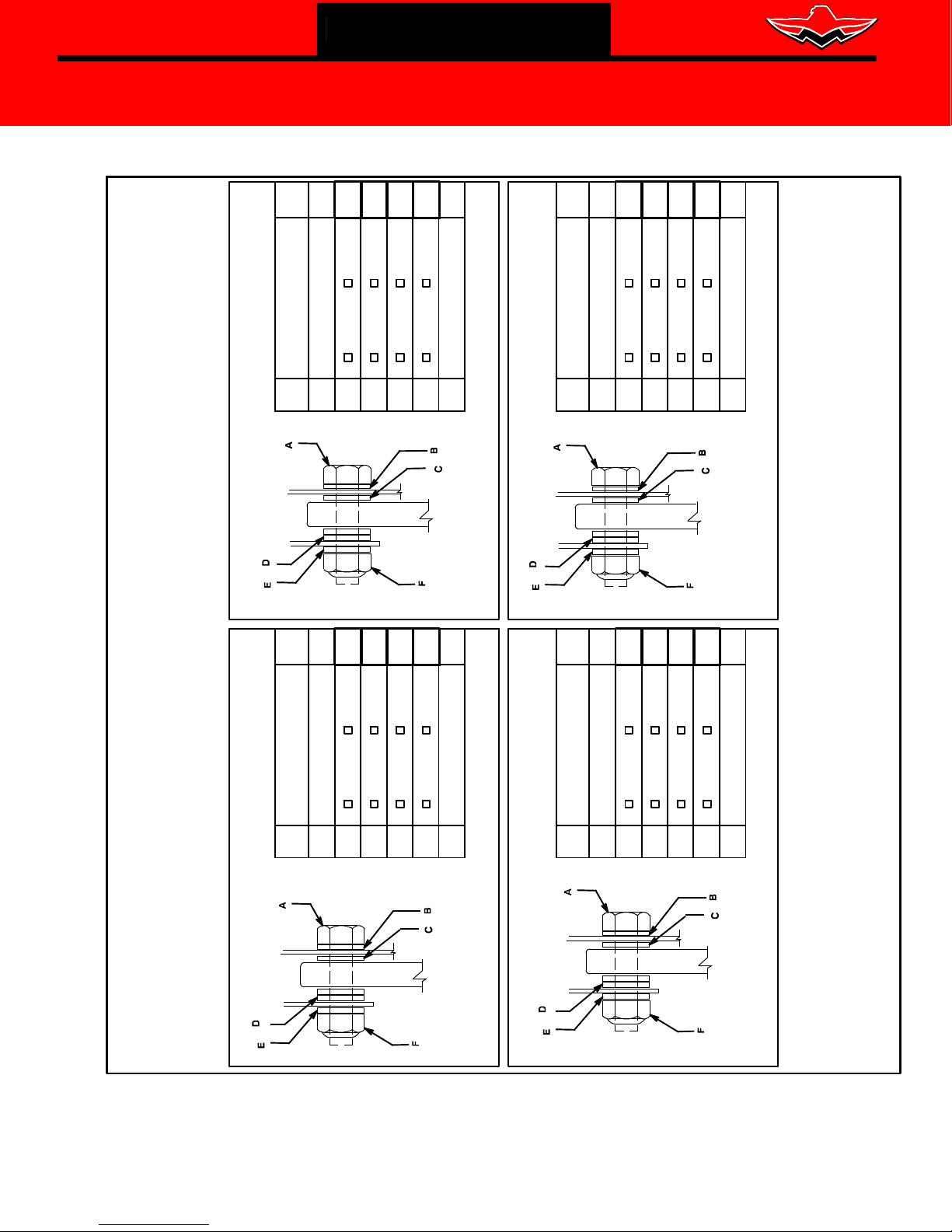
2.3. Remove attaching hardware at rudder hinges, note each hinge hardware on zone chart(s) Figure
SIM20-335-8.
MOONEY INTERNATIONAL CORPORATION 165 Al Mooney Road North, Kerrville, T exas 78028 tel: 830-896-6000 www.mooney.com
SBM20-335B Page 1

MOONEY INTERNATIONAL
CORPORATION
165 Al Mooney Road North
Kerrville, Texas 78028
THIS BULLETIN DOES NOT CHANGE AIRCRAFT TYPE DESIGN
2.4. Secure and stow control rods to prevent damage to painted skins.
2.5. Remove rudder by pulling it straight aft.
2.6. Balance rudder to specifications found in Chapter 27- 91- 00 of the applicable Mooney Service
and Maintenance Manual and Mooney Spec 20 Section 35, be sure to install all static wicks
and Strobe Light (if removed).
2.7. Fill out Flight Control Balance Sheets from Figures SIM20-335-9 and SIM20-335-10 for
balance criteria
SERVICE BULLETIN
SERVICE BULLETIN M20-335B
Date: January 2, 2019
.
2.8.
If Balance is within Specifications, continue to STEP 2.10.
2.9. If Balance is NOT within Specifications, continue to STEP 3 - Adding or Replacing Weight..
2.10. Re- Install IN reverse sequence as removed, refer to Chapter 5 in the applicable Service and
Maintenance Manual for hardware torque values. Refer to
SIM20-335-8 for stack- up of hardware (use new nuts and cotter pins upon reassembly).
ELEVATOR REMOVAL/INSTALLATION - Refer to Figure SIM20-335-2
Rudder Hinge Zone chart Figure
NOTE:
It may be feasible to use a roll of duct tape to hold the Elevator at a slight angle, to aid the removal of
hardware. Damage could occur if extending Elevator at extreme angles.
NOTE:
Keep Control Yoke from moving in/out with a piece of PVC or suitable tube, as
damage could occur if control rod assembly snags on painted skins.
2.11.
2.12. Remove bolts, nuts and washers from the four attaching hinges, note each hinge hardware on
Disconnect elevator push pull tubes, by removing removing Bolt AN3-10, Washers
NAS1149F0332P, Nut MS17825-3 and Cotter Pin MS24665-151, refer to Figure
SIM20-335-2.
zone chart(s) LH Figure SIM20-335-6 and RH Figure SIM20-335-7 as required., refer to
Figure SIM20-335-2.
2.13. Remove both elevators by pulling it straight aft.
2.14. Balance elevators to specifications found in Chapter 27- 91- 00 of the applicable Mooney Service
and Maintenance Manual and Mooney Spec 20 Section 35, be sure to install static wicks
(if removed).
2.15. Fill out Flight Control Balance Sheets from Figures SIM20-335-9 and SIM20-335-10 for
balance criteria.
2.16.
If Balance is within Specifications, continue to STEP 2.18.
2.17. If Balance is NOT within Specifications, continue to STEP 3 - Adding or Replacing Weights.
2.18. Re- Install IN reverse sequence as removed, refer to Chapter 5 in the applicable Service and
Maintenance Manual for hardware torque values. Refer to Elevator
Figure SIM20-335-6 and RH Figure SIM20-335-7
and cotter pins upon reassembly).
MOONEY INTERNATIONAL CORPORATION 165 Al Mooney Road North, Kerrville, T exas 78028 tel: 830-896-6000 www.mooney.com
Hinge Zone chart(s) LH
for stack- up of hardware (use new nuts
SBM20-335B Page 2

MOONEY INTERNATIONAL
CORPORATION
165 Al Mooney Road North
Kerrville, Texas 78028
THIS BULLETIN DOES NOT CHANGE AIRCRAFT TYPE DESIGN
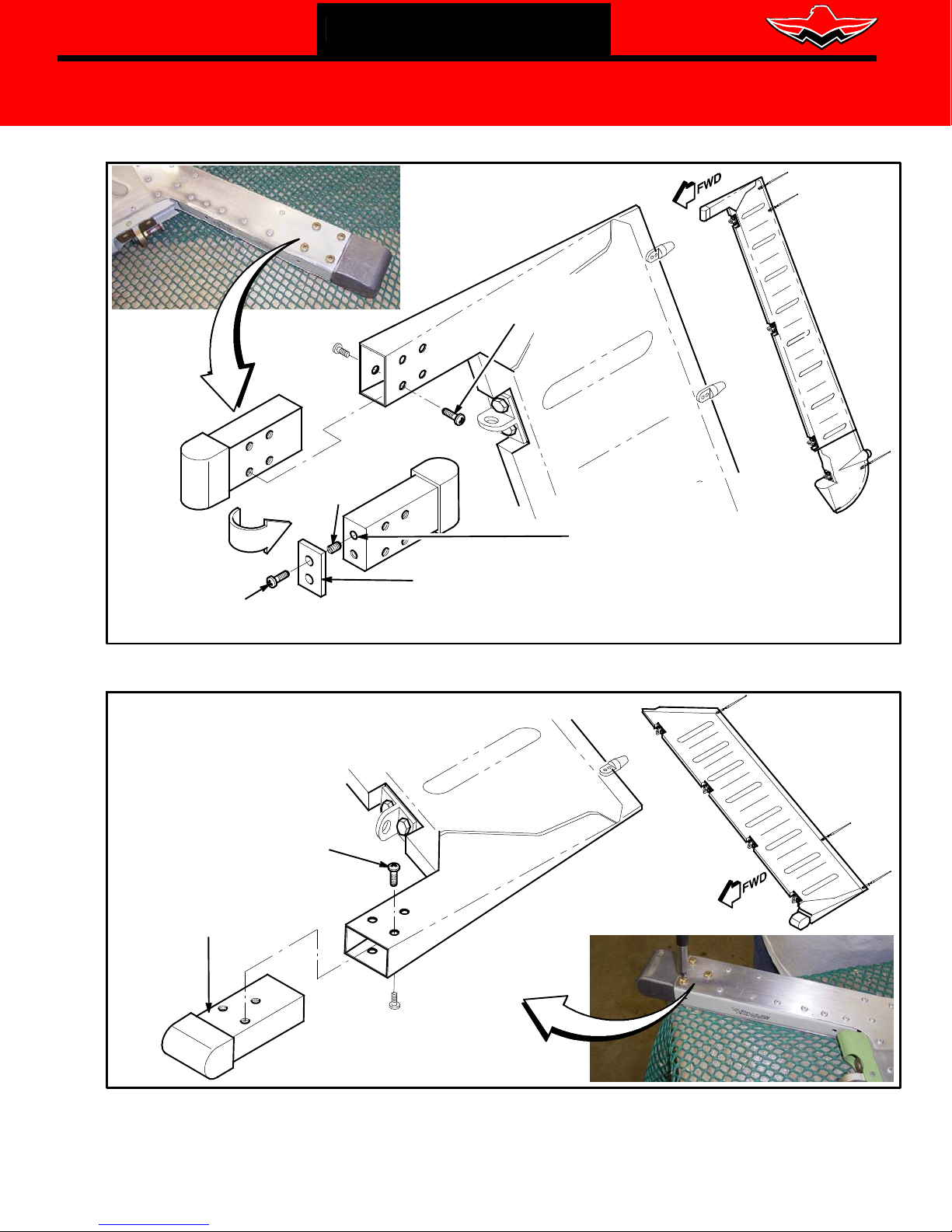
STEP 3 - Adding or Replacing Weights on Rudder and/or Elevator Flight Control
It may be required to slightly file (with rasp) control weight(s) to fit in flight control slot.
Use Proper Handling of Lead Control Weight(s) Personal Protective Equipment (PPE) gloves, non - per-
meable clothing and approved respirators are recommended.
3.1. Contact Mooney Product Support for details on adding weight.
Adding weight to Rudder (Top Weight Only): WEIGHT LIMIT (LBS) MAX = 3.85 AND MIN = 3.20
3.2a. Remove factory counterweight from Rudder by, removing (8) NAS623- 3- 1 screws (keep for
reassembly, refer to
3.2b. Add additional weight(s) 430055-003 as required, based on STEP 2 - Checking Flight
Control Balance, match them to end of factory weight and drill (2) .203” .010” diameter
thru added weights at a depth of .41” into end of factory counterweight as required, refer to
Figure SIM20-335-3. Drill slowly and use care when drilling weight to prevent drill bit
breakage. The use of “Boelube”, “Wax” or “Soap” is recommended on drill bit to prevent
breakage.
3.2c. Install (2) Helicoil inserts R1191-3 to both newly drilled holes in counterweight. Use Loctite
271 on helicoil inserts when installing.
3.2d. Temporarily install added weight(s) 430055-003 with (2) MS35207-XXX to new holes in
factory counter weight and Install counterweight to elevator with (6) NAS623- 3- 1 screws,
hand tighten only and balance per instruction in STEP 2 - Checking Flight Control
3.2e. When balance has been verified and within tolerance as specified in Mooney Service Manual
and Mooney Spec 20 Section 35, Install added weight(s) and correct length screws to holes
in factory counterweight, Using Loctite 222 on screws, hand tighten only. DO NOT OVER
TIGHTEN, doing so will pull helicoil inserts from weight..
3.2f. Install counterweight to Rudder with (8) NAS623- 3- 1 screws, hand tighten only.
DO NOT OVERTIGHTEN, doing so will pull helicoil inserts from weight.
3.2g. Touch-up paint as required, per Mooney Service and Maintenance Manual Chapter 20, refer
to Aircraft paint kit for color(s), contact Mooney Service Parts for availability.
3.2h. Install Rudder per STEP 2 - Checking Flight Control
SERVICE BULLETIN
SERVICE BULLETIN M20-335B
Date: January 2, 2019
NOTE:
CAUTION:
Figure SIM20-335-3.
Balance
Balance
Installing new weight to Elevator (LH/RH): WEIGHT LIMIT (LBS) MAX = 4.22 AND MIN = 4.00
3.3a. Remove factory counterweight from Elevator by, removing (6) NAS623- 3- 1 screws (keep
for reassembly, refer to
3.3b.
Temporarily install new weight 430055- 501 to Elevator with (6) NAS623-3-1, hand tighten only.
DO NOT OVERTIGHTEN, doing so will pull helicoil inserts from weight.
3.3c. Balance per STEP 2 - Checking Flight Control Balance, if balancing needs material to be
removed from factory counterweight, continue to
continue to STEP 3.3e.
3.3d.
Clamp the lead weight in a vice and use a rasp to trim the cone end of the weight until it weighs
the specific number from the b
3.3e. Install counterweight to Elevator with (6) NAS623- 3- 1 screws, hand tighten only.
DO NOT OVERTIGHTEN, doing so will pull helicoil inserts from weight.
3.3f. Touch-up paint as required, per Mooney Service and Maintenance Manual Chapter 20, refer
to Aircraft paint kit for color(s), contact Mooney Service Parts for availability..
3.3g. Install elevator(s) per STEP 2 - Checking Flight Control
MOONEY INTERNATIONAL CORPORATION 165 Al Mooney Road North, Kerrville, T exas 78028 tel: 830-896-6000 www.mooney.com
Figure SIM20-335-4.
STEP 3.3d, if balance is within tolerance
alance check per STEP 2 - Checking Flight Control Balance,
Balance
SBM20-335B Page 3

MOONEY INTERNATIONAL
CORPORATION
165 Al Mooney Road North
Kerrville, Texas 78028
THIS BULLETIN DOES NOT CHANGE AIRCRAFT TYPE DESIGN
STEP 4 - Return Aircraft To Service
4.0 RETURN TO SERVICE - Refer to the applicable Service and Maintenance Manual
4.1. Inspect flight controls for full travel, proper rigging, free- play, binding, security of mounting, proper
lubrication and proper direction of control surface movement with relation to control wheel
movement, refer to Chapter 27 of the applicable Service and Maintenance Manual.
SERVICE BULLETIN
SERVICE BULLETIN M20-335B
Date: January 2, 2019
4.2.
Check tail strobe operation.
4.3. Confirm level flight, refer to Chapter 27 of the applicable Service and Maintenance Manual.
4.4. Send all Flight Control Balance Sheets from
to support@mooney.com for aircraft records.
Figures SIM20-335-9 and SIM20-335-10,email
4.4. Remove Placard M20-335-901 or M20-335-902 from Instrument Panel.
NOTE:
Fill out compliance card and send by MAIL or FAX to Mooney International Corporation as
indicated on the attached Compliance Card. (See Figure SBM20-335-11).
4.5. Return aircraft to service.
4.6. Procedure complete.
WARRANTY: Mooney International Corporation will warrant labor 8 hours in accordance with procedures of
this Service Bulletin for aircraft currently covered under the Mooney International Corporation
factory warranty program.
Mooney International Corporation will warrant labor 2 additional hours per Flight Control requiring
balancing in accordance with procedures of this Service Bulletin for aircraft currently covered
under the Mooney International Corporation factory warranty program.
REFERENCE 1. Applicable Mooney Service and Maintenance Manual
DATA: 2. Product Support email: support@mooney.com or phone: 830-792-2919
3. Applicable Mooney Illustrated Parts Catalog
4. Mooney Spec 20 Section 35 (attached)
PARTS LIST: Mooney International Corporation, Service Bulletin Parts Kit(s): Not Ordered As Kit
Order parts as required below:
Item
P/N Description Qty
1. M20-335-901 Placard (for M20R and M20TN) 1
2. M20-335-902 Placard (for M20U and M20V) 1
3. 430055-003 Weight Bar (as required to Balance Rudder Assembly) A/R
4. R1191-3 Helicoil Insert (Mounting Added Rudder Weight) 2
5. MS35207-XXX Screw 10-32 x (XXX=Length determined by # weights) A/R
6. 430055-501 Weight, Elevator (file as required for Balance) 1
7. 222 Loctite, Low Strength (Shop Supplied) AR
8. 271 Loctite, Permanent (Shop Supplied) AR
MOONEY INTERNATIONAL CORPORATION 165 Al Mooney Road North, Kerrville, T exas 78028 tel: 830-896-6000 www.mooney.com
(Shop Supplied Hardware)
SBM20-335B Page 4
MOONEY INTERNATIONAL
CORPORATION
165 Al Mooney Road North
Kerrville, Texas 78028
THIS BULLETIN DOES NOT CHANGE AIRCRAFT TYPE DESIGN
PLACARD M20-335-901
LIMITATION:
MAXIMUM AIRCRAFT
SPEED 127 KIAS
29-0520 THRU 29-0528
31-0128 THRU 31-0143
SERVICE BULLETIN
SERVICE BULLETIN M20-335B
Date: January 2, 2019
NOTE: CLEAN SURFACE
WITH ISOPROPYL ALCOHOL
BEFORE APPLYING PLACARD
PLACARD M20-335-902
LIMITATION: MAXIMUM AIRCRAFT SPEED 127 KIAS
32-0001, 32-0003
33-0004, 33-0006, 33-0007
Figure SBM20-335-1 - PLACARDS, INSTRUMENT PANEL
MOONEY INTERNATIONAL CORPORATION 165 Al Mooney Road North, Kerrville, T exas 78028 tel: 830-896-6000 www.mooney.com
NOTE: CLEAN SURFACE
WITH ISOPROPYL ALCOHOL
BEFORE APPLYING PLACARD
SBM20-335B Page 5
MOONEY INTERNATIONAL
CORPORATION
165 Al Mooney Road North
Kerrville, Texas 78028
THIS BULLETIN DOES NOT CHANGE AIRCRAFT TYPE DESIGN
BOLT
AN3-11A
WASHER
NAS1149F0332P
SERVICE BULLETIN
STATIC WICKS (3)
SERVICE BULLETIN M20-335B
WASHER
NAS1149F0332P
Date: January 2, 2019
BOLT
AN3-11A
WASHER
NAS1149F0332P
MS21045-L3
ROLL OF TAPE
NUT
STATIC WICKS (3)
WASHER
NAS1149F0332P
SEE
NOTE
DETAIL D
DETAIL E
SEE
NOTE
WASHER
NAS1149F0332P
NUT
MS21045-L3
ELEVATOR PUSH
PULL CONTROL TUBES
TAIL STROBE
HARNESS
STATIC WICKS (3)
DETAIL H
NUT
MS21045-L3
DETAIL G
WASHER
NAS1149F0332P
BOLT
AN3-11A
NOTES:
USE AN960-10 AND/OR AN960-10L BETWEEN HINGE BLOCKS TO
ELIMINATE POSSIBLE GAPS AND END PLAY.
NAS1149F0363P THICK WASHER SAME AS AN960- 10
NAS1149F0332P THIN WASHER SAME AS AN960- 10L
Figure SBM20-335-2 - RUDDER AND ELEVATOR INSTALLATION
MOONEY INTERNATIONAL CORPORATION 165 Al Mooney Road North, Kerrville, T exas 78028 tel: 830-896-6000 www.mooney.com
SEE
NOTE
NUT
MS21045-L3
BOLT
AN3-7A
DETAIL F
WASHER
NAS1149F0332P
WASHER
NAS1149C0332R
WASHER
NAS1149F0363P
WASHER
NAS1149F0332P
SBM20-335B Page 6
MOONEY INTERNATIONAL
CORPORATION
165 Al Mooney Road North
Kerrville, Texas 78028
THIS BULLETIN DOES NOT CHANGE AIRCRAFT TYPE DESIGN
SERVICE BULLETIN
SEE NOTE:
HELICOIL (2)
R1191-3
SCREWS (8)
(REUSE FROM DISASSEMBLY)
NAS623-3-1
DRILL .203” HOLE
TO A DEPTH
OF .41 FOR HELICOIL
IN EXISTING WEIGHT
NOTE:
SERVICE BULLETIN M20-335B
Date: January 2, 2019
SCREW (2)
MS35207-XXX
LENGTH DETERMINED
BY QUANTITY OF WEIGHTS
Figure SBM20-335-3 - RUDDER ADDED WEIGHT INSTALLATION
SCREW (6)
SCREW (6)
NAS623-3-1
(REUSE FROM DISASSEMBLY)
(REUSE FROM DISASSEMBLY)
WEIGHT (IF REQUIRED)
NAS623-3-1
430055-501
WEIGHT (AS REQUIRED)
430055-003
MAXIMUM WEIGHT NOT TO
EXCEED 3.85 LBS
Figure SBM20-335-4 - ELEVATOR ADDED WEIGHT INSTALLATION
MOONEY INTERNATIONAL CORPORATION 165 Al Mooney Road North, Kerrville, T exas 78028 tel: 830-896-6000 www.mooney.com
SBM20-335B Page 7
MOONEY INTERNATIONAL
CORPORATION
165 Al Mooney Road North
Kerrville, Texas 78028
THIS BULLETIN DOES NOT CHANGE AIRCRAFT TYPE DESIGN
SERVICE BULLETIN
SERVICE BULLETIN M20-335B
Date: January 2, 2019
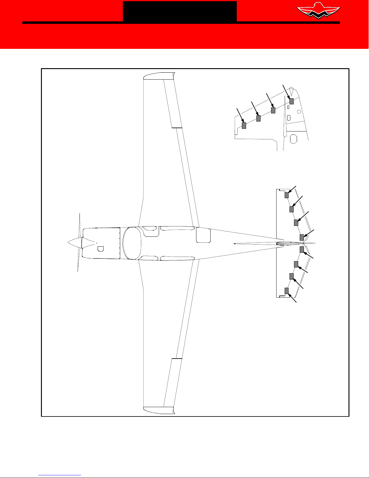
R4
R3
R2
R1
RUDDER HINGE ZONE
RHE1
RH ELEVATOR
LH ELEVATOR
RHE2
RHE3
HINGE ZONE
RHE4
LHE4
LHE3
HINGE ZONE
LHE2
LHE1
Figure SBM20-335-5 - OVERALL LOCATION OF CONTROL SURFACE HINGE ZONES
MOONEY INTERNATIONAL CORPORATION 165 Al Mooney Road North, Kerrville, T exas 78028 tel: 830-896-6000 www.mooney.com
SBM20-335B Page 8

MOONEY INTERNATIONAL
CORPORATION
165 Al Mooney Road North
Kerrville, Texas 78028
THIS BULLETIN DOES NOT CHANGE AIRCRAFT TYPE DESIGN
SERVICE BULLETIN
SERVICE BULLETIN M20-335B
Date: January 2, 2019
LHE2
1
QTY
Description
Part Number
Item
QTY
Thick Thin
Thick Thin
Thick Thin
AN3-11A BOLT
A
B
C
D
1
1
Thick Thin
MS210N44-N3 NUT
F
E
1
LHE4
1
QTY
Description
Part Number
Item
QTY
Thick Thin
Thick Thin
Thick Thin
AN3-11A BOLT
A
B
C
D
1
1
Thick Thin
MS210N44-N3 NUT
F
E
1
LH ELEVATOR HINGE ZONES
Description
Part Number
*Note - Denote "Thick" and/or "Thin" washer shim and quantity
LHE1
AN3-11A BOLT
A
Item
Thick Thin
Thick Thin
Thick Thin
B
C
Thick Thin
MS210N44-N3 NUT
D
F
E
LHE3
Description
Part Number
AN3-11A BOLT
A
Item
Thick Thin
Thick Thin
B
Thick Thin
Thick Thin
MS210N44-N3 NUT
C
D
F
E
NAS1149F0363P SAME AS AN960-10 (.063 Thick)
NAS1149F0332P SAME AS AN960-10L (.032 Thin)
NOTE:
Figure SBM20-335-6 - LH ELEVATOR HINGE ZONE CHART
MOONEY INTERNATIONAL CORPORATION 165 Al Mooney Road North, Kerrville, T exas 78028 tel: 830-896-6000 www.mooney.com
SBM20-335B Page 9
MOONEY INTERNATIONAL
CORPORATION
165 Al Mooney Road North
Kerrville, Texas 78028
THIS BULLETIN DOES NOT CHANGE AIRCRAFT TYPE DESIGN
SERVICE BULLETIN
SERVICE BULLETIN M20-335B
Date: January 2, 2019
RHE2
1
QTY
Description
Part Number
Item
QTY
Thick Thin
Thick Thin
Thick Thin
AN3-11A BOLT
A
B
C
D
1
1
Thick Thin
MS210N44-N3 NUT
F
E
1
1
QTY
Description
Part Number
Item
QTY
Thick Thin
Thick Thin
Thick Thin
AN3-11A BOLT
A
B
C
D
1
1
Thick Thin
MS210N44-N3 NUT
F
E
1
RH ELEVATOR HINGE ZONES
Description
Part Number
*Note - Denote "Thick" and/or "Thin" washer shim and quantity
RHE1
MOONEY INTERNATIONAL CORPORATION 165 Al Mooney Road North, Kerrville, T exas 78028 tel: 830-896-6000 www.mooney.com
Item
Figure SBM20-335-7 - RH ELEVATOR HINGE ZONE CHART
Description
RHE3 RHE4
Part Number
Item
Thick Thin
AN3-11A BOLT
A
B
Thick Thin
Thick Thin
C
Thick Thin
MS210N44-N3 NUT
D
F
E
NAS1149F0363P SAME AS AN960-10 (.063 Thick)
NAS1149F0332P SAME AS AN960-10L (.032 Thin)
NOTE:
Thick Thin
AN3-11A BOLT
A
B
Thick Thin
Thick Thin
C
Thick Thin
MS210N44-N3 NUT
D
F
E
SBM20-335B Page 10
MOONEY INTERNATIONAL
CORPORATION
165 Al Mooney Road North
Kerrville, Texas 78028
THIS BULLETIN DOES NOT CHANGE AIRCRAFT TYPE DESIGN
SERVICE BULLETIN
SERVICE BULLETIN M20-335B
Date: January 2, 2019
R2
UP
1
QTY
Description
Part Number
Item
Thick Thin
AN3-11A BOLT
A
B
Thick Thin
Thick Thin
C
D
1
Thick Thin
MS210N45-L3 NUT
F
E
1
QTY
Description
Part Number
AN3-7A BOLT
A
Item
1
Thick Thin
B
Thick Thin
NAS1149C0332R WASHER
C
D
1
Thick Thin
MS210N45-L3 NUT
F
E
UP
DOWN
1
QTY
1
1
QTY
DOWN
1
RUDDER HINGE ZONES
Description
Part Number
AN3-11A BOLT
*Note - Denote "Thick" and/or "Thin" washer shim and quantity
R1
A
Item
Thick Thin
Thick Thin
Thick Thin
B
C
Thick Thin
MS210N45-L3 NUT
D
F
E
R3 R4
UP
DOWN
UP
Description
Part Number
AN3-11A BOLT
A
Item
Thick Thin
Thick Thin
Thick Thin
B
C
Thick Thin
MS210N45-L3 NUT
D
F
E
DOWN
NAS1149F0363P SAME AS AN960-10 (.063 Thick)
NAS1149F0332P SAME AS AN960-10L (.032 Thin)
NOTE:
Figure SBM20-335-8 - RUDDER HINGE ZONE CHART
MOONEY INTERNATIONAL CORPORATION 165 Al Mooney Road North, Kerrville, T exas 78028 tel: 830-896-6000 www.mooney.com
SBM20-335B Page 11

MOONEY INTERNATIONAL
CORPORATION
165 Al Mooney Road North
Kerrville, Texas 78028
THIS BULLETIN DOES NOT CHANGE AIRCRAFT TYPE DESIGN
SERVICE BULLETIN
SERVICE BULLETIN M20-335B
Date: January 2, 2019
Figure SBM20-335-9 - FLIGHT CONTROL BALANCE SHEET
MOONEY INTERNATIONAL CORPORATION 165 Al Mooney Road North, Kerrville, T exas 78028 tel: 830-896-6000 www.mooney.com
SBM20-335B Page 12
 Loading...