

Mooney M20S 1998 Maintance Manual
SERVICE
OLDWILLWAYNE
A~19
PbI~Uat
IC~
M
AI
~T
T
E
~b
A
E
ORIGINAL
Pu~OO
~3
E
Y
ECERRVILLE,
NOV.,
AIRC
LOUIS
1998
C-~
RBFT
SCHREINER
TEXAS
COR
FIELD
780~8
MANUAL
O
P
R
NUMBER
ATIO
~J
iao
MOONEY
OLDWILLWAYNE
AIRCRAFT
COPORATION
KERRVILLE,
TEXAS
WARNING:
harm
public
This
warning
stalled
on
the
health
applies
Mooney
Manufactured
environment
and
to
placards
Aircraft
with
manufactured
Model(s)
1,1,1
destroying
by
addressed
Trichloroethane
ozone
at
Mooney
this
in
substances
in
the
upper
Aircraft
publication.
which
atmosphere.
Corporation
are
determined
facility
and
to
in-
WARNING:
harm
public
This
warning
Mooney
Aircraft
Manufactured
health
applies
Model(s)
and
to
environment
certain
addressed
with
adhesives
1,1,1
destroying
by
in
this
Trichloroethane
ozone
procured
publication.
from
substances
the
in
vendors
upper
atmosphere.
and
which
utilized
are
on
determined
the
applicable
to
MOONEY
OLDWILLWAYNE
AIRCRAFT
CORPORATION
M20S
SERVICE
AND
MAINTENANCE
MANUAL
LCIG
DP1TE
REVISION
OF
[1F
REVISIONS
SECTIONS
AF~FECTED
Always
destroy
superseded
DATE
REVISION
OF
paaes
when
you
insert
revised
SECTICINS
AFFECTED
NOT
A
list
EI
of
effective
oaaes
will
aDoear
at
the
keainnina
of
each
chaDter,
MOONEY
OLDWILLWAYNE
AIRCRAFT
CORPORATION
M20S
SERVICE
MAINTENANCE
AND
MANUAL
INTRODUCTION
manual
This
formation
30-0001
bers
fer
to
a
serial
by
The
Part
should
log
~applicable
worked
Mooney
any
ceptions
The
format
accordance
in
TURER’S
Specification
with
wiring
airplanes,as
at
lopes
Revisions
not
holders.
Technical
information
at
Schreiner
provides
the
for
limited
be
on.
and
number
Number’s
identified
The
Service
Electrical
on
and
ASSOCIATION
No.
schematics
necessary.
the
back
automatically
Holders
Publications
the
front
Mooney
Field,
Mooney
number
of
Model
to
correct
contents
with
2.
of
reissues
or
the
on
of
Aircraft
ON.
Service
Notification
another
tion
out.
service.
sired,
craft
manual
and
The
new
If
contact
Corporation
Correspondence
numbers
model
appears
aft
zontal
end,
num
on
left
stabilizer.
ASSIGNMENT
:e~eel:ontent
is
advises
additional
on
an
ber
the
hand
of
sent
is
that
manual
the
above
at
concerning
airplane
and
identification
side
OF
this
prepared
serial
Group
Chapter(System)
GROUP
These
able
tems
identified
are
broad
VS
Section
Subject
primary
separation
Powerplant
tabs.
by
(Sub´•system)
(Unit)
divisions
servicing
Model
Maintenance
of
aircraft
applicable
of
replacement
the
using
and
P/N
Center.
Components.
of
this
GENERAL
The
manual
for
These
the
manual
NOTE
provided
of
these
should
"YELLOW
the
Title
Corporation,
Kerrville,
Parts
Department.
to
known
no
more
will
require
Technical
department
896-6000,
(830)
should
number.
the
of
SUBJECT
publication
of
content,
systems.
and
M20S,
airplanes,
Illustrated
S/N
be
can
See
SECTION
manual
AVIATION
(GAMA)
the
various
are
texts
of
this
and
CARD’’
Page
TX.,
manual
to
replace
revisions
a
Publications
maintenance
contain
placard
tailcone
MATERIAL
is
of
the
These
maintenance
Serial
actions
be
will
or
repair
aircraft
of
ordered
are
is
supplemented
model
located
pages.
manual
to
manual
other
complete
and
send
Louis
78028,
holders
the
will
new
subscription
at
Mooney
ext.
the
The
serial
located
below
organired
manual
Airframe
ie.,
groups
Num´•
that
designated
parts
%ata´•
Parts
being
through
91
for
ex-
prepared
MANUFAC-
year
in
enve´•
are
Mooney
the
located
to
Attn:
when
subscrip-
be
sent
de-
are
Air´•
2092.
or
part
aircraft
number
the
on
hori´•
the
four
at
that
en´•
sys-
are
in´•
re-
CHAPTER
various
The
tion
such
systems
mended
are
number
ample,that
number
refers
tems.
The
into
by
re.,
bution
The
identified
bers,
manufacturer
ing
recommended.
Mooney
vising
tions
any
will
person
tribution
as
tion.
within
ney
come
"28’.
to
SECTION
major
sub-systems.
second
the
28´•20´•00.
portion
SUBJECT
individual
ie.,28´•20´•01.
upon
APPLICATION
Aircraft
all
GAMA
to
publication
conform
wishing
,28´•20-00,
These
each
series
more
quentially
The
table
provide
the
If
HAND
then
(Left
will
the
a
Chapter.
there
is
or
the
Hand)
apply
publications.
(System)
groups
as
flight
arranged
"Fuel"
The
the
General
(Sub-System)
systems
element
The
of
(Unit)
units
third
a
by
and
the
complexity
Corporation
applicable
format.
concerning
this
to
information
System
in
any
pages
system
of
aircraft.
complex
numbered
of
contents
list
of
systems
For
example:
28´•00
28-10
28´•20
28-40
a
reason
RIGHT
number
and
28-40-02
to
any
contain
controls,
numerically
assignment,
be
identified
sequence
information
of
an
These
element
the
may
OF
sub-systems
of
fuel
system.
within
element
This
number
or
of
NUMBERING
maintenance
When
basic
would
refer
maintenance
will
be
breakdown
As
Mooney
the
page
within
in
the
and/or
General
Storage
(Tanks,
etc.)
Distribution
(Boost
etc.)
Indicating
(Sender
gauges,
to
HAND
would
distinguish
fuel
be
(Right
expanded
major
landing
It
is
suggested
with~
of
numbers,
aircraft
the
sequence
´•20-
indicates
a
sub´•system
the
of
sequence
is
not
may
the
maintenance
isinthe
technical
this
effort
maintenance
concerning
the
to
numbered
in
aircraft
numbers
sub-systems.
front
of
subjects
vents,
pumps,
Units,
etc.)
quantity
expanded
Hand).
information
systems
gear,
%AMA
per
the
the
of
broken
are
are
of
assigned
be
used
SYSTEM
process
is
the
pages
onented
sequentially
current
the
each
repair,
fuel
lines,
quantity
between
sending
to
This
informa´•
etc.
recom´•
for
Chapter
28-00´•00,
Fuel
down
identified
numbers,
distri´•
the
may
of
num´•
by
depend´•
action
of
publica´•
completed
of
aircraft
Fuel
identified
publica´•
Moo´•
models
be
may
Chapter
covered
LEFT
units
28~40´•01
concept
throughout
The
ex´•
Sys´•
be
the
re´•
Any
Dis-
be´•
se´•
will
in
INTRODUCTION
INTRODUCTION´•1
SERVICE
OLDWILLWAYNE
AND
MAINTENANCE
MAN
UAL
M20S
MOONEY
AIRCRAFT
CORPORATION
The
following
on
components
listed
due
repair
Any~eublications
available
stations
through
As
publications
ENGINE
The
following
Products,
Overhaul
Illustrated
Maintenance
Service
Fuel
Injector
ACCESSORY
list
the
to
through
Mooney
PUBLICATIONS
P.O.
Manual
Parts
Bulletins
Manual,
PROPELLER
McCauley
dalia,
Propellers
0~.,45377.
of
Manufacturers
of
the
Mooney,
configurations
many
for
a
particular
available
Mooney
any
Aircraft
various
on
maintenance
Box
90,
Mobile,
for
Teledyne
Catalog
Operators
Specify
Form
PUBLICATIONS
Obtain
Model
avionics
from
Mooney
Service
Corporation,
components
VENDOR
publications
Alabama,
Continental
for
Teledyne
Manual
model
for
of
X30593A
publications
SUPPLEMENTARY
and/or
publications
M20S.
that
can
manufacturer.
Aircraft
Center.
these
should
become
ADDRESSES
can
No
be
be
USA,
Motors
Continental
Teledyne
enginefor
Continental
which
from
PUBLICATIONS
avionics
installed
Corporation
Most
manufacturer/vendor
be
obtained
available,
obtained
36601,
Aircraft
Motors
maintenance
McCauley
can
provide
equipment
in
the
are
will
they
PUBLICATIONS
through
Attn:
Accounts
10-550
10-550
Motors
Accessories
aircraft.
from
Engine
series
data
servicing
listed
the
added
be
Teledyne
aircraft
10-550
is
Division,
and
Manufacturers
These
in
the
publications
applicable
the
to
Continental
Receivable
Models,
engines,
aircraft
desired
3535
maintenance
or
publications
be
can
Parts
obtained
Price
are
Manufacturer/Vendor.
list
below.
Motors,
(Prepaid
Form
X30568A.
Form
engines,
when
Form
ordering.
McCauley
information
List
not
only).
X30569A.
from
and
availabel
X30565.
Drive,
are
the
are
Aircraft
Van-
Service
MAGNETO
Teledyne
cations
ALTERNATOR
Alternator
90,
Mobile,
STARTER
Service
36601,
FUEL
Teledyne
cations
IGNITION
Master
Aircraft
tors,
SPEED
Precise
Manual
Continental
Dept.,
Service
Alabama,
Manual,
Attn:
PUMP
Continental
Dept
Service
Flight,
No.
TCM
for
Instructions,
Teledyne
Publications
(Engine
SYSTEM
Manual,
Products,
BRAKES
Inc.,
780630
Motors,
USA,
Motors,
63120
(Bendix),
36601,
Continental
Dept
Driven)
TCM
P.O.
Box
Powell
for
McCauley
Aircraft
Type
Form
Aircraft
Ignition
90,
Butte
Products,
S6RN´•25
X30531-3,
Attn:
Motors,
Products,
Systems
Mobile,
C200
Publications
Alabama,
Rd.,
Bend,
series
P.O.
Series
Teledyne
Aircraft
P.O.
and
Components,
OR
constant
Box
90,
magnetos.
Continental
Dept.
Products,
Box
90,
USA,
97701,
speed
Mobile,
Mobile,
Form
36601,
Telephone:
propellers.
Alabama,
Motors,
P.O.
Alabama,
X40000,
Attn:
Aircraft
Box
90,
Publications
(503)
USA,
Products,
Mobile,
USA,
36601,
Teledyne
382-8684
36601,
Alabama,
Continental
Dept
Attn:
Attn:
P.O.
Publi-
Box
USA,
Publi´•
Mo´•
INTRODUCTION-2
INTRODUCTION
MOONEY
OLDWILLWAYNE
AIRCRAfT
CORPORATION
M20S
SERVICE
AND
MAINTENANCE
MANUAL
CHAPTER
4
1
5
6
7
8
9
CHAPTER-
SECTION
SECTION
00
10
20
00
10
00
00
10
20
30
TITLE
INDU(GUIDE
TITLE
RESERVED
LIMITS/MAINTENANCE
TIME
GENERAL
TIME
SCHEDULED
DIMENSIONS
GENERAL
LIFTING
JACKING
LEVELING
LEVELING
TOWING
GROUND
TOWING
TAXIING
EMERGENCY
LIMITS
AND
AND
MAY
MAINTENANCE
AND
WEIGHING
TAXIING
HANDLING
PROCEDURES
USED
BE
AREAS
LATER
CHECKS
CHECKS
20
21
24
10
11
12
00
10
20
00
10
20/30
00
10
20
00
00
40
50
60
00
30
40
50
PARKING
AND
GENERAL
PARKING
MOORING
PLACARDS
AND
GENERAL
MARKINGS
PLACARDS
SERVICING
SERVICING
REPLENISHING
SCHEDULED
STANDARD
PRACTICES
GENERAL
ENVIRONMENTAL
CABIN
HEATING
VENTILATION
COOLING
TEMPERATURE
ELECTRICAL
GENERAL
DC
GENERATION
EXTERNAL
ELECTRICAL
MOORING
MARKINGS
EXTERIOR/INTERIOR
SERVICING
AIRFRAME
SYSTEMS
SYSTEM
CONTROL
POWER
POWR
LOAD
DISTRIBUTION
INTRODUCTION
INTRODUCTION-3
SERVICE
OLDWILLWAYNE
AND
MAINTENANCE
MANUAL
M20S
MOONEY
AIRCRAFT
CORPORATION
CHAPTER
25
27
28
THISSECTION
INCLUDED
MAYNOTBE
IN
THIS
SECTION
00
M.
10
20
50
60
70
00
10
20
30
40
50
60
90
00
10
20
30
40
90
S
TITLE
EQUIPMENT/FURNISHI
GENERAL
FLIGHT
PASSENGER
CARGO
EMERGENCY
ACCESSORY
FLIGHT
GENERAL
AILERON
RUDDER
ELEVATOR
STABILIZER
WING
INTERCONNECT
MISCELLANEOUS
FUEL
GENERAL
STORAGE
DISTRIBUTION
DUMP
INDICATING
MISCELLANEOUS
COMPARTMENT
COMPARTMENT
COMPARTMENT
EQUIPMENT
COMPARTMENT
CONTROLS
SYSTEM
SYSTEM
SYSTEM
TRIM
SYSTEM
FLAP
SYSTEM
NGS
30
32
33
34
00
10
30
40
60
00
10
20
30
40
50
60
80
00
10/20
40
00
10
20
AND
RAIN
ICE
GENERAL
AIRFOIL
PITOT
AND
WINDSHIELDS
PROPELLERS
LANDING
GEAR
GENERAL
MAIN
NOSE
LANDING
LANDING
EXTENSION
WHEELS
AND
STEERING
POSITION
MISCELLANEOUS
LIGHTS
GENERAL
INTERIOR
PRACTICES
EXTERIOR
PRACTICES
NAVIGATION
GENERAL
PITOT
STATIC
SYSTEM
DIRECTIONAL
PROTECTION
STATIC
GEAR
GEAR
AND
BRAKES
WARNING
AND
LIGHTS
LIGHTS
AIR
GYRO
AND
AND
RETRACTION
MAINTENANCE
MAINTENANCE
PRESSURE
COMPASS
DOORS
DOORS
I
NTROD
UCTI
ON
´•4
NTROD
1
UCTI
ON
MOONEY
OLDWILLWAYNE
AIRCRAFT
CORPORATION
M20S
SERVICE
AND
MAINTENANCE
MANUAL
CHAPTER
35
37
39
51
52
SECTION
THIS
INCLUDED
SECTION
TITLE
OXYGEN
GENERAL
CREW/PASSENGERS
MAY
NOT
THIS
S
IN
M.
BE
00
10/20
VACUUM
00
10
20
30
40
00
10
GENERAL
DISTRIBUTION
INDICATING
REPAIR
OPERATIONAL
ELECTRICAL
COMPONENTS
GENERAL
INSTRUMENT
PROCEDURES
PANELS
AND
AND
CONTROL
PANELS
ELECTRONICS
20
ELECTRICAL
EQUIPMENT
AND
RACKS
STRUCTURES
00
10
GENERAL
STRUCTURAL
REPAIR
GENERAL
DOORS
00
10
30
GENERAL
CABIN
DOOR
PRACTICE
BAGGAGE
MAINTENANCE
MAINTENANCE
COMPARTMENT
PRACTICE
DOOR
53
55
56
57
00
10
20
30
40
50
00
10
20
30
40
00
10/20
50
00
10
20
30
40
50
FUSELAGE
GENERAL
FRAME
MAIN
AUXILIARY
PLATES/SKIN
ATTACH
FITTINGS
FILLETS/FAIRINGS
STABILIZERS
GENERAL
HORIZONTAL
ELEVATOR
VERTICAL
RUDDER
WINDOWS
GENERAL
WINDSHIELD
PLEXIGLASS
WINGS
GENERAL
FRAME
MAIN
AUXILIARY
PLATES/SKINS
ATTACH
FLIGHT
FITTINGS
SURFACES
STRUCTURE
STABILIZER
STABILIZER
CABIN
DRILLING
STRUCTURE
WINDOWS
INTRODUCTION
INTRODUCTION-5
SERVICE
OLDWILLWAYNE
AND
MAINTENANCE
MANUAL
M20S
MOONEY
AIRCRAFT
CORPORATION
CHAPTER
60
61
71
72
73
SECTION
00
10
20
40
00
10
20
30
60
00
00
10
20
30
TITLE
STANDARD
PROPELLERS
PROPELLERS
GENERAL
PROPELLER
CONTROLLING
BALANCING
POWERPLANT
GENERAL
COWLING
MOUNTS
FIRESEALS
NTAKES
AIR
I
ENGINE
GENERAL
ENGINE
FUEL
GENERAL
DISTRIBUTION
CONTROLLING
INDICATING
PRACTICES
ASSEMBLY
PROCEDURES
RECIPROCATING
SYSTEM
79
74
76
77
78
40
00
30
40
00
20
00
00
20
30
00
30
20
50
10
10
10
10
10
IGNITION
GENERAL
POWER
EMERGENCY
ENGINE
GENERAL
POWER
ENGINE
GENERAL
POWER
TEMPERATURE
PRESSURE
EXHAUST
GENERAL
INSTALLATION
EXHAUST
REPLACEMENT
OIL
GENERAL
STORAGE
DISTRIBUTION
INDICATING
TRANSDUCERS
TROUBLE
CONTROL
SHUTDOWN
CONTROLS
CONTROLS
INDICATING
INDICATING
SYSTEM
SHOOTING
RIGGING
COMPONENTS
80
INTRODUCTION-6
00
10
STARTING
GENERAL
CRANKING
INTRODUCTION
MOONET
OLDWILLWAYNE
AIRCRAFT
CORPORATION
M20S
SERVICE
AND
MAINTENANCE
MANUAL
CHAPTER
81
91
95
SECTION
THIS
INCLUDED
SECTION
MAY
NOT
THIS
S
IN
M.
BE
00
00
20
30
TITLE
TURBINES
GENERAL
SCHEMATICS
GENERAL
ELECTRICAL
CHARTS
SCHEMATICS
SPECIAL
SYSTEM
EQUIPMENT
HARDWARE
INTRODUCTION
INTRODUCTION-7
SERVICE
OLDWILLWAYNE
AND
MAINTENANCE
MANUAL
M20S
MOONEY
AIRCRAFT
CORPORATION
BLANK
INTRODUCTION-8
INTRODUCTION
CHAPTER
OLDWILLWAYNE
MAINTENANCE
TIME,
CH
LIMITSI
EC
KS
SERVICE
OLDWILLWAYNE
AND
MAINTENANCE
MANUAL
M20S
MOONEY
AIRCRAFT
CORPORATION
CHAPTER
SECTION
SUBJECT
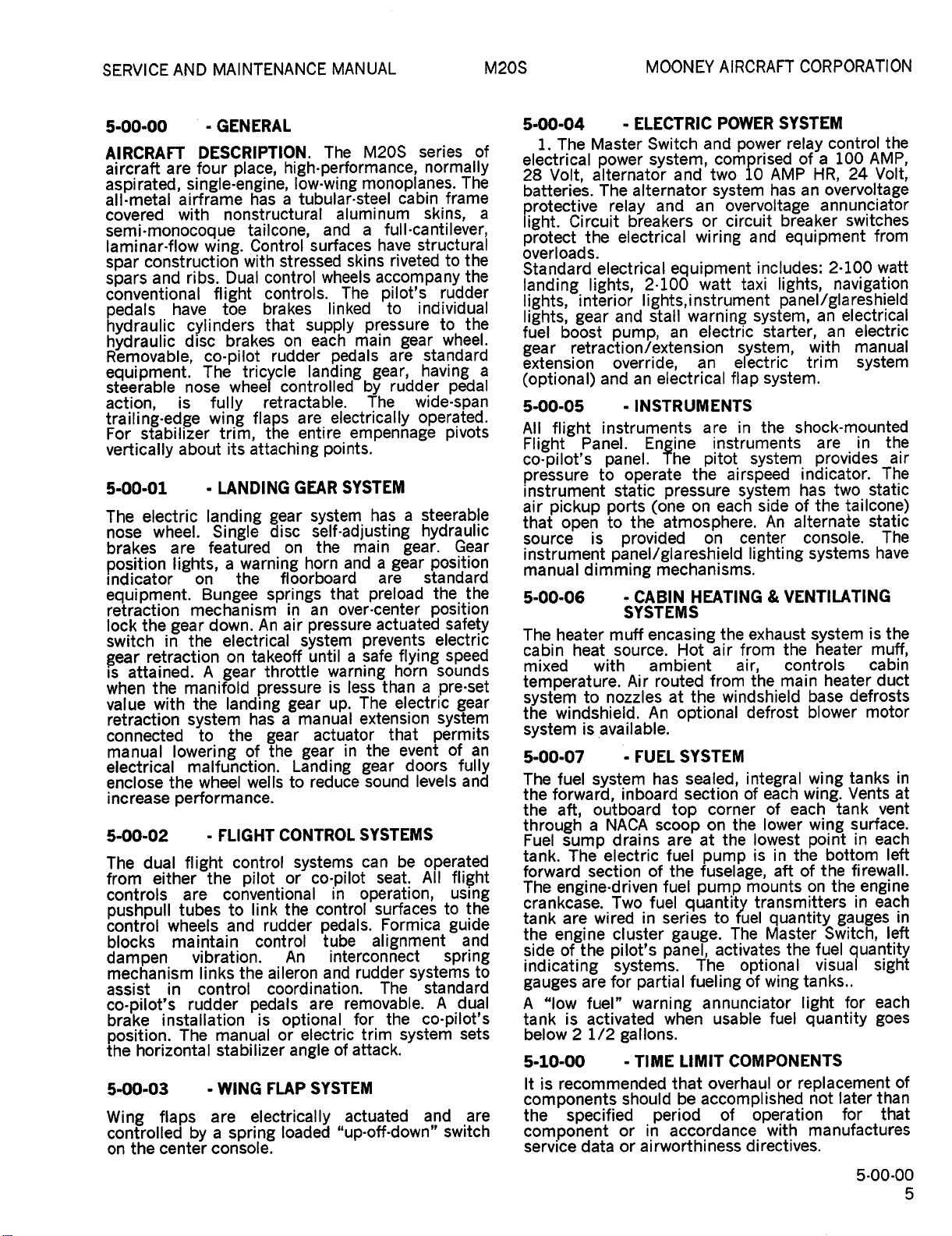
5-Effectivity
5-Contents
5-00´•00
5-10-00
5-20-01
5-20-01
5-20´•01
5-20´•01
5-20-02
5-20-06
5´•20´•06
5-20-06
5-20-06
5-20-06
5-20-07
5´•20´•07
5-20-07
5´•20-07
LIMITS/MAINTENANCE
TIME
LIST
OF
1/2BLANK.
3/4BLANK.
CHAPTER
EFFECTIVE
PAGE
5.
6.
7.
8.
9.
10.
11.
12.
13.
14.
15.
16.
17.
18.
19.
20.
5
CHECKS
PAGES
DATE
11-98
11-98
11-98
11-98
11-98
11-98
11´•98
11-98
11´•98
11-98
11-98
11-98
11-98
11-98
11-98
11´•98
11-98
11-98
5-EFFECTIVITY
1/2BLANK

MOONEY
OLDWILLWAYNE
AIRCRAFT
CORPORATION
M20S
SERVICE
MAINTENANCE
AND
MANUAL
CHAPTER
SECTION
SUBJECT
5´•00-00
5´•00´•01
5-00-02
5-00-03
5-00-04
5-00-05
5-00´•06
5-00-07
5-10-00
5-10-01
5-20-00
5-20-01
5-20-02
5-20-03
5-20-04
5-20-05
5-20-06
5-20-07
LIMITS/MAINTENANCE
TIME
TABLE
General.
Landing
Flight
Wing
Electric
Instruments
Cabin
Fuel
Time
Schedule
CHAPTER
OF
SUBJ
Gear
Control
Flap
Power
Heating
System
Limit
Overhaul
Maintenance
Check
Aircraft
Engine
First
25
50
Hour
Hour
100
Access
Lubrication
5
CONTENTS
ECT
System
Systems.
Systems.
System
Ventilating
Components
and
Replacement
Points,
Functional
File
Hour
Torque
Inspection
Inspection
Inspection
Inspection
Cover
Identification,
and
CHECKS
Checks
Values
Check.
Service
Sy;tems
Schedule
Guide
PAGE
5
5
5
5
5
5
5
5
6
6
6
7
11
11
11
11
12
17
5-CONTENTS
3/4BLANK
SERVICE
OLDWILLWAYNE
MAINTENANCE
AND
MANUAL
M20S
MOONEY
AIRCRAFT
CORPORATION
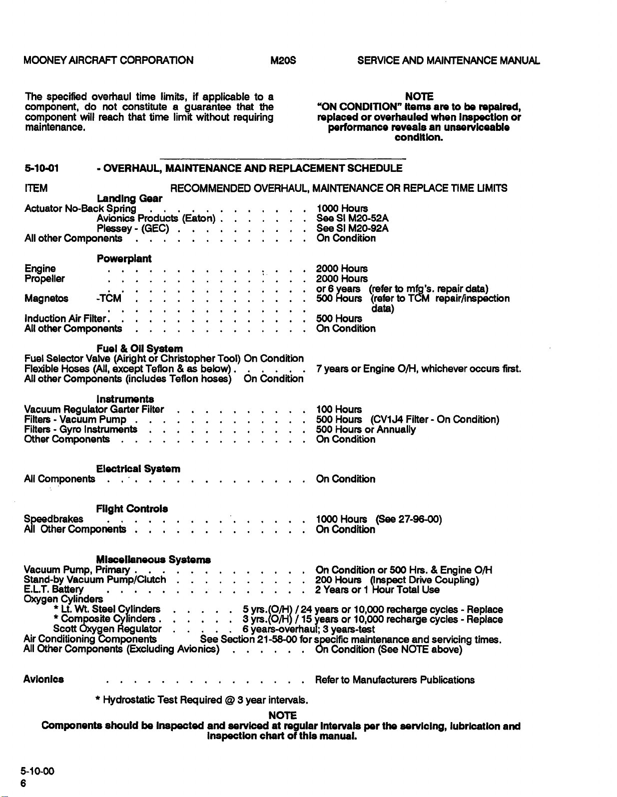
5-00-00
AIRCRAFT
aircraft
aspirated,
all´•metal
covered
DESCRIPTION.
four
are
single-engine,
airframe
with
semi´•monocoque
laminar´•flow
construction
spar
and
spars
conventional
pedals
hydraulic
hydraulic
Removable,
equipment.
steerable
action,
trailing-edge
stabilizer
For
vertically
5-00-01
electric
The
position
nose
brakes
Indicator
wheel.
equipment.
retraction
the
lock
switch
retraction
gear
attained.
is
the
when
value
connected
with
retraction
manual
electrical
enclose
increase
5-00-02
dual
The
eitherthe
from
controls
pushpull
control
blocks
dampen
mechanism
assist
co-pllot’s
bra’ke
position.
the
horizontal
5-00-03
Wing
controlled
the
on
wing.
ribs.l)ual
have
cylinders
dlsc
co-pilot
The
nose
is
wing
about
landing
featured
are
lights,
on
Bungee
mechanism
down.
gear
the
in
A
manifold
the
system
to
lowering
malfunction.
the
wheel
performance.
flight
are
tubes
wheels
i
ntai
ma
vibration.
links
control
in
rudder
installation
The
flaps
by
center
GENERAL
place,
has
nonstructural
tailcone,
Control
with
flight
toe
brakes
tricycle
wheel
fully
flaps
trim,
its
LANDING
Single
a
warning
the
electrical
takeoff
on
gear
pressure
landing
has
the
of
wells
FLIGHT
control
pilot
conventional
link
to
and
cent
n
the
pedals
manual
stabilizer
WING
are
electrically
a
spring
console.
M20S
The
high-performance,
low-wing
tubular´•steel
a
surfaces
stressed
control
controls.
brakes
that
supply
each
on
rudder
landing
controlled-bX~udder
ret
cta
ra
are
entire
the
monoplanes.
aluminum
and
a
skins
wheels
The
linkedilot’s
pressure
main
pedals
gear,
ble.
electrically
empennage
series
normally
cabin
skins,
full-cantilever,
structural
have
riveted
accompany
individual
gear
standard
are
having
operated.
of
The
frame
the
to
the
rudder
the
to
wheel.
pedalwide-span
pivots
points.
SYSTEM
system
self-adjusting
main
the
and
horn
rd
that
over-center
an
pressure
system
until
prevents
safe
a
warning
less
is
The
up.
manual
actuator
gear
reduce
extension
in
gear
SYSTEMS
can
co-pilot
in
operation,
control
pedals.
tube
interconnect
and
rudder
nation.
i
removable.
are
for
of
trim
attack.
electric
SYSTEM
actuated
"up-off-down"
has
a
gear.
a
gear
are
preload
actuated
flying
horn
than
electric
that
the
event
doors
sound
be
seat.
surfaces
Formica
alignment
systems
The
the
system
steerable
hydraulic
Gear
position
ndard
sta
thethe
position
safety
electric
speed
sounds
a
pre´•set
gear
system
permits
of
fully
ana
levels
operated
All
flight
using
to
guide
and
spring
standard
dual
A
co´•pilot’s
sets
and
switch
an
the
to
are
gear
disc
on
ii
springs
In
air
An
throttle
a
gear
the
CONTROL
or
the
rudder
An
aileron
coord
is
optional
or
FLAP
loaded
GEAR
oorboa
gear
Landing
to
systems
rol
angle
a
a
5-00-04
Master
The
i.
electrical
28
Volt,
batteries.
protective
lights,
Circuit
lights,
interior
gear
boost
retraction/extension
light.
Standard
landing
lights,
fuel
gear
extension
(optional)
5-00-05
All
flight
Flight
Panel.
co-pilot’s
pressure
instrument
air
pickup
that
open
source
instrument
manual
5-00-06
The
cabin
mixed
is
dimming
heater
heat
temperature.
system
the
system
5-00-07
The
the
the
through
Fuel
tank.
forward
The
crankcase.
tank
the
side
to
windshield.
is
fuel
system
forward,
aft,
a
sump
The
section
engine-driven
are
engine
the
of
indicating
gauges
A
tank
below
5-10-00
It
are
fuel"
"low
activated
is
2
recommended
is
1/2
components
the
specified
component
service
data
ELECTRIC
Switch
alternator
relay
breakers
electrical
system,
and
and
equipment
power
alternator
The
electrical
2´•100;
lights,instrument
stall
and
pump,
an
override,
and
instruments
to
ports
to
electrical
an
-INSTRUMENTS
operate
static
pressure
tone
the
atmosphere.
provided
panel/glareshield
mechanisms.
CABIN
SYSTEMS
muff
encasing
source.
Air
nozzles
inboard
NACA
drains
electric
Two
cluster
pilot’s
ambient
An
FUEL
has
of
fuel
in
routed
at
top
scoop
are
fuel
the
fuel
series
gauge.
panel,
with
available.
outboard
wired
systems.
for
partial
warning
when
gallons.
TIME
that
should
period
accordance
in
or
airworthiness
or
POWER
and
comprised
two
system
an
overvoltage
circuit
or
wiring
watt
warning
electric
an
flap
are
instruments
pitot
the
airspeed
each
on
on
HEATING
the
Hot
air
from
windshield
the
optional
SYSTEM
sealed,
section
corner
the
on
the
at
pump
fuselage,
pump
quantity
to
The
activates
The
fueling
annunciator
usable
LIMIT
be
COMPONENTS
overhaul
accomplished
of
SYSTEM
AMP
10
has
and
includes:
relay
breaker
equipment
lights,
power
taxi
panel/glareshield
system,
starter,
system,
electric
system.
in
shock-mounted
the
system
system
side
of
alternate
An
center
lighting
VENTILATING
exhaust
the
from
the
defrost
controls
main
air,
integral
of
each
each
of
lower
lowest
the
is
in
aft
mounts
transmitters
fuel
quantity
Master
the
optional
of
wing
fuel
or
operation
with
directives.
control
100
of
a
24
HR,
an
overvoltage
annunciator
switches
2´•100
navigation
electrical
an
electric
an
manual
with
trim
are
system
in
provides
indicator.
has
two
the
tailcone)
console.
systems
heater
tank
bottom
the
gauges
is
defrosts
motor
tanks
Vents
surface.
in
firewall.
engine
in
system
heater
base
blower
wing
wing.
wing
point
the
of
on
Switch,
fuel
qua
visual
tanks..
for
light
quantity
replacement
later
not
for
manufactures
5-00-00
the
AMP,
Volt,
from
watt
the
air
The
static
static
The
have
the
muff,
cabin
duct
in
at
vent
each
left
each
in
left
each
goes
of
than
that
MOONN
OLDWILLWAYNE
AIRCRAFT
CORPORATION
M20S
SERVICE
MAINTENANCE
AND
MANUAL
The
specified
component,
component
maintenance,
5-10-01
ITEM
Actuator
All
other
Engine
Propeller
Magnetos
Induction
All
other
Selector
Fuel
Flexible
All
Hoses
other
overhaul
do
not
will
reach
OVERHAUL
Landing
No-Back
Spring
Avionics
Plessey
Components
Powerplant
-T~M’
Air
Filter..
Components
Fuel
Valve
(All,
Components
time
constitute
that
limits,
time
if
a
guarantee
limit
without
MAINTENANCE
RECOMMENDED
Gear
(GEC)
011
System
(AirightorChristopher
except
(includes
Teffon
Teflon
as
below)
applicable
requiring
Tool)
hoses)
to
that
the
AND
OVERHAUL,
On
Condition
dn
i=ot;dit’ion’
a
"ON
replaced
REPLACEMENT
MAINTENANCE
1000
See
See
On
2000Hours
2000Hours
or
500Hours
500
OnCondition
7
CONDITION"
or
performance
SCHEDULE
Hours
M20-52A
SI
SI
M20-92A
Condition
6
years
Hours
or
years
Engine
overhauled
reveals
condition.
OR
to
(refer
(referto
data)
NOTE
Items
REPLACE
whichever
O/H,
be
to
are
when
unserviceable
an
inspection
LlME
repaired,
UMITS
repairdata)
repair/inspection
occurs
or
first.
Vacuum
Filters-Vacuum
Filters
Other
All
SDeedbrakes
All
Vacuum
Stand-by
E.L.’T.
Oxygen
Regulator
Instruments
Gyro
Components
Components
OtherComponentF;
Pump,
Vacuum
Battery
Cylinders
Wt.
Lt.
Composite
Scott
Air
Conditioning
Other
All
Avionics
Oxygen
Component~
Instruments
Garter
Filter
Pump
Electrical
Controls
Flight
Miscellaneous
Primary
Pump/Cl;tch
Steel
Cylinders
Cylinders.
Regulator
Components
(Excluding
System
Systems
Avionics)
~ee
Section
5
yrs.(O/H)
6
yrs.(O/H)
6
years-overhaul;
21-5800
100
Hours
Hours
500
Hours
500
On
Condition
On
Condition
1000Hours
Condition
On
On
Condition
Hours
200
Years
2
/24
years
/15
years
for
specific
On
RefertoManufacturers
or
or
3
years-test
Condition
or
10,000
10,000
maintenance
(CV1J4
or
Filter-
Annually
(See27-96-00)
Hrs.
500
or
[Inspsct
Hour
1
(See
Drive
Total
recharge
recharge
NOTE
On
Coupling)
Use
cycles
cycles
and
servicing
above)
Publications
Condition)
Engine
O/H
Replace
Replace
times.
Components
5-10-00
Hydrostatic
should
be
Test
Required
Inspected
S
serviced
and
Inspection
year
intervals.
NOTE
at
chart
regular
of
this
Intervals
manual.
per
the
servicing,
lubrication
end
SERVICE
OLDWILLWAYNE
AND
MAINTENANCE
MANUAL
M20S
MOONEY
AIRCRAFT
CORPORATION
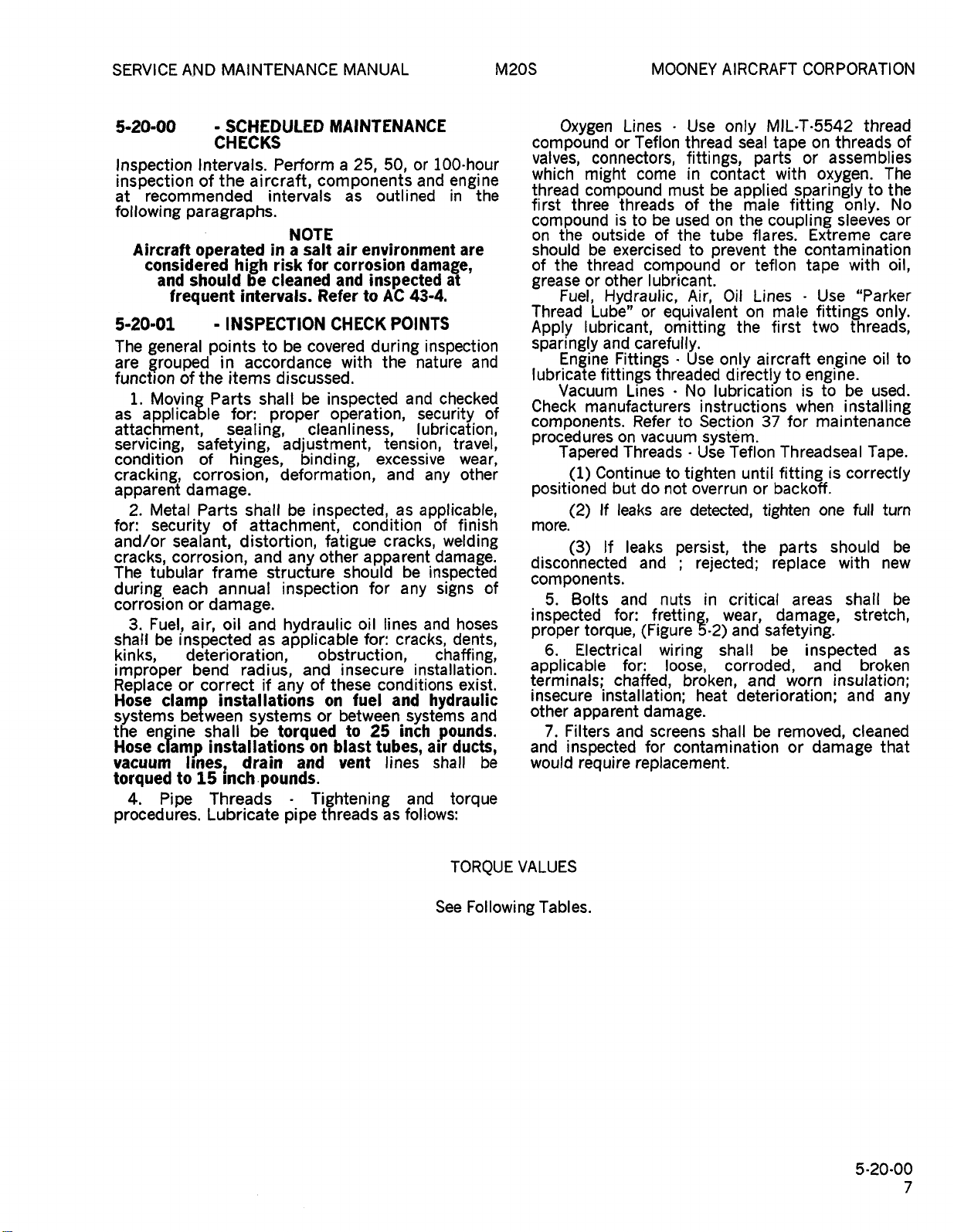
5-20-00
Inspection
inspection
recommended
at
following
Aircraft
considered
and
frequent
5-20-01
The
general
are
grouped
function
i.
as
of
Moving
applicable
attachment,
servicing,
condition
cracking,
apparent
Metal
2.
for:
security
and/or
cracks,
The
during
corrosion
shall
3.
sealant,
corrosion,
tubular
each
Fuel,
be
inspected
kinks,
improper
Replace
Hose
systems
the
Hose
vacuum
torqued
4.
or
clamp
between
engine
clamp
to
Pipe
procedures.
SCHEDULED
CHECKS
Intervals.
the
of
ai
paragraphs.
operated
high
should
he
intervals.
INSPECTION
points
in
accordance
the
items
Parts
for:
sealing,
safetying,
of
hinges,
corrosion,
damage.
Parts
shall
of
attachment,
distortion,
and
frame
annual
or
damage.
oil
air,
and
deterioration,
bend
radius,
correct
installations
systems
shall
be
installations
Ilnes
15
Threads
Lubricate
drain
jnch’
Perform
rcraft,
intervals
NOTE
in
a
risk
cleaned
to
be
discussed,
shall
proper
adjustment,
binding,
deformation,
be
any
structure
inspection
hydraulic
as
applicable
if
any
torqued
and
pounds.
pipe
MAINTENANCE
a
25,
com
ponents
as
salt
air
for
corrosion
and
Refer
CHECK
covered
with
be
inspected
operation,
cleanliness,
inspected,
condition
fatigue
other
should
obstruction,
insecure
and
of
these
fuel
on
between
or
to
blast
on
vent
Tightening
threads
50,
outlined
environment
damage,
inspected
A%
43-4.
to
POINTS
during
the
and
tension,
excessive
and
as
cracks,
apparent
be
for
any
oil
lines
for:
cracks,
conditions
and
systems
25
inch
tubes,
lines
and
follows:
as
100´•hour
or
and
engi
in
are
af
inspection
nature
checked
security
lubrication,
travel,
wear,
other
any
applicable,
of
finish
welding
damage,
inspected
signs
and
hoses
dents,
chaffing,
installation.
exist,
hydraulic
pounds.
air
ducts,
shall
torque
the
and
and
be
threads
assemblies
only.
sleeves
with
Use
"Parker
threads,
to
be
installing
is
correctly
full
one
should
with
shall
stretch,
insulation;
and
cleaned
thread
to
care
only.
oil
used.
Tape.
turn
new
broken
that
of
The
the
No
or
oil,
to
be
be
as
any
Oxygen
compound
valves,
ne
which
th’ead
first
three
compound
the
on
should
of
the
grease
Fuel,
Thread
Apply
sparingly
Engine
lubricate
Vacuum
of
Check
components.
p’ocedures
Tapered
(1)
positioned
(2)
more.
(3)
disconnected
components.
of
Bolts
5.
inspected
proper
Electrical
6´•
applicable
terminals;
insecure
Other
apparent
7.
Filters
and
inspected
would
Lines
Teflon
or
connectors,
might
compound
threads
istobe
outside
be
exercised
thread
other
or
Hydraulic,
Lube"
lubricant,
and
carefully.
Fittings
fittings
Lines
manufacturers
on
Threads
Continue
but
If
leaks
If
leaks
and
for:
Refer
torque,
for:
chaffed,
installation;
and
require
come
vacuum
and
replacement.
Use
thread
fittings,
in
must
of
used
of
the
to
compound
lubricant.
Air,
or
equivalent
omitting
Use
threaded
No
to
to
tighten
do
not
overrun
are
detected,
persist,
nuts
fretting,
(Figure
wiring
loose,
broken,
damage.
screens
for
contamination
only
seal
contact
be
applied
the
the
on
tube
prevent
or
Oil
the
only
directly
lubrication
instructions
Section
systim.
Use
Teflon
rejected;
in
critical
wear,
and
5´•2)
shall
corroded,
heat
deterioration;
shall
MIL´•T´•5542
tape
parts
with
male
coupling
flares.
the
teflon
Lines
male
on
first
aircraft
37
until
backoff.
or
tighten
the
replace
damage,
safetying.
be
and
be
removed,
on
or
oxygen.
sparingly
fitting
Extreme
contamination
tape
fittings
two
en~gine
to
engine.
is
when
for
maintenance
Threadseal
fitting
parts
areas
inspected
and
worn
or
damage
TORQUE
See
Following
VALUES
Tables.
5´•20´•00
MOONEY
OLDWILLWAYNE
AIRCRAFT
CORPORATION
M20S
SERVICE
MAINTENANCE
AND
MANUAL
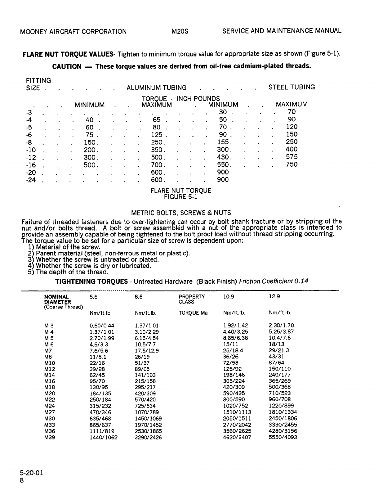
FLARE
FITTING
SIZE
.3
´•4
´•5
-6
-8
´•10
-12
-16
-20
´•24
Failure
and/or
nut
provide
The
torque
1)
2)
3)
4)
5)
NUT
of
an
Material
Parent
Whether
Whether
The
depth
TORQUE
CAUTION
threaded
bolts
assembly
value
to
of
the
material
the
screw
the
screw
of
TIGHTENING
VALUES-
MINIMUM
40
60
75
150
200.
300.
500.
fasteners
thread.
capable
be
set
screw.
(steel,
thread.
the
These
torque
due
bolt
A
of
for
a
non-ferrous
untreated
is
is
or
dry
TORQUES
Tighten
values
ALUMINUM
METRIC
to
over-tightening
screwassemgld~
or
being
tightened
particular
or
lubricated.
Untreated
minimum
to
TORQUE
MAXI~IUM
65
80
125
250.
350.
500.
700
600.
600.
FLARE
BOLTS,
size
metal
plated.
are
TUBING
FIGURE
to
of
or
plastic).
Hardware
torque
derived
INCH
NUT
can
the
screw
from
POUNDS
TORQUE
5-1
SCREWS
occur
with
bolt
is
dependent
(Black
value
a
proof
for
appropriate
oil-free
MINIMUM
30
50
70
90
155.
300
430
550.
900
900
NUTS
bolt
by
of
nut
load
Finish)
cadmium-plated
shank
the
without
upon:
fracture
appropriate
thread
Friction
site
as
STEEL
MAXIMUM
or
stripping
Coefficient
shown
threads.
70
90
120
150
250
400
575
750
by
class
TUBING
stripping
is
0.14
(Figure
of
intended
occurring.
5-1).
the
to
5-20-01
NOMINAL
DIAMETER
(Coarse
M3
M4
M5
M6
M7
M8
M10
M12
M14
M16
M18
M20
M22
M24
M27
M30
M33
M36
M39
Thread)
5.6
Nm/ft.lb.
0.60/0.44
1.37/1.01
2.70/1.99
4.6/3.3
7.6/5.6
11/8.1
22/16
39/28
62/45
95/70
130/95
184/135
250/184
315/232
470/346
635/468
865/637
1111/819
1440/
1062
8.8
Nm/ft.lb.
1.37/1.01
3.10/2.29
6.15/4.
10.5/7.7
17.5/12.9
26/19
51/37
89/65
141/103
215/158
295/217
420/309
570/420
725/534
1070/789
1450/
1970/1452
2530/
3290/2426
54
1069
1865
PROPERTY
CLASS
TORQUE
Ma
10.9
Nm/ft.
1.42
1.92/
40/3.
4.
8.
65/6.
15/11
25/18.4
36/26
72/53
125/92
198/146
305/224
420/309
590/435
800/590
1020/752
1510/1113
2050/1511
2770/2042
3560/2625
4620/3407
12.9
Ib.
25
38
Nm/ft.lb.
2.
30/1.70
5.
25/3.
10.4/7.6
18/13
29/21.3
43/33
87/64
150/110
240/177
365/269
500/368
710/523
960/708
1220/899
1810/1334
2450/
3330/2455
4280/3156
5550/4093
87
1806
SERVICE
OLDWILLWAYNE
AND
MAINTENANCE
MANUAL
M20S
MOONEY
AIRCRAFT
CORPORATION
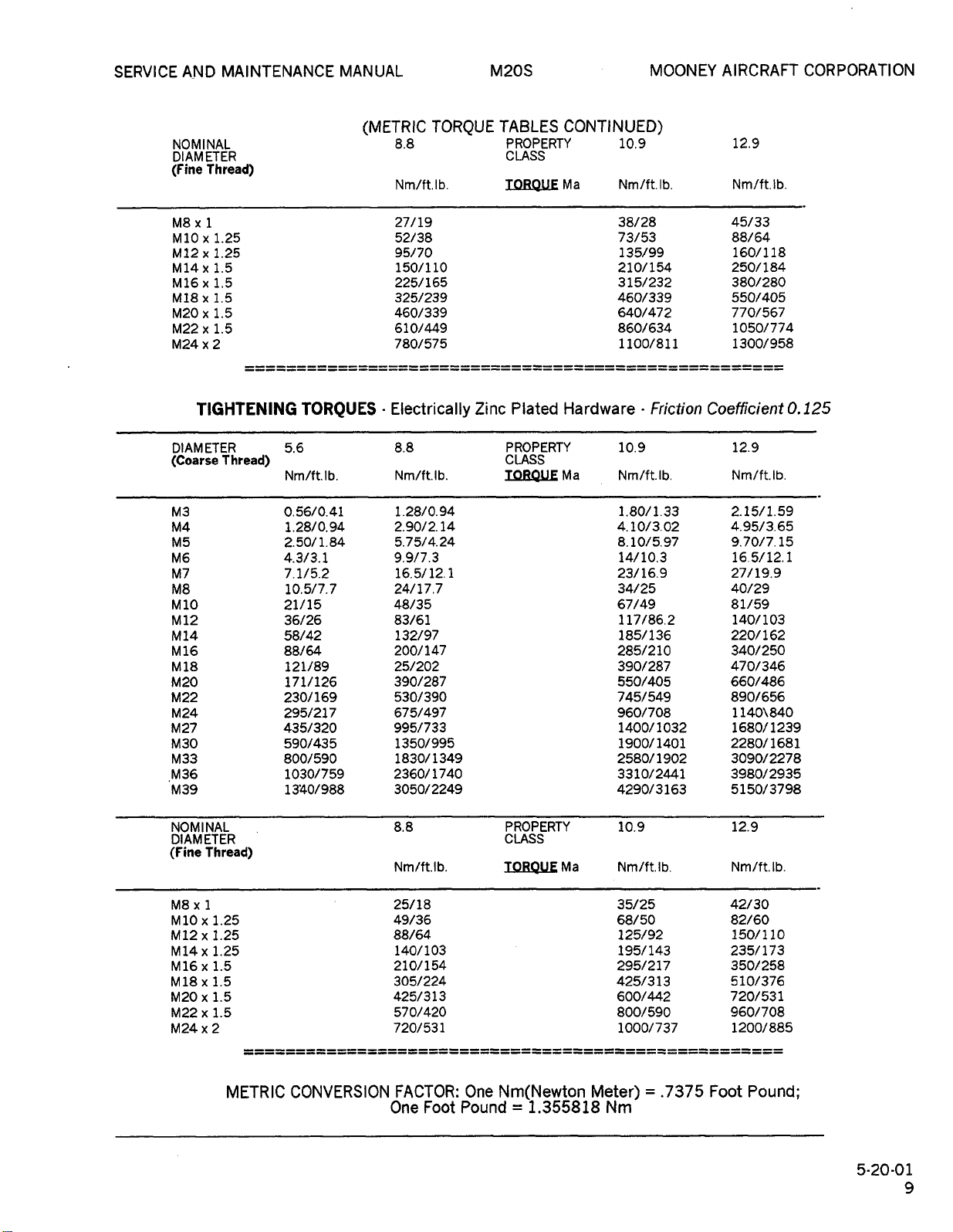
NOMINAL
DIAMETER
(Fine
Thread)
M8x1
M10
x
M12x1.25
M14x1.5
M16x1.5
M18x1.5
M20x1.5
M22x1.5
M24x2
TIGHTENING
DIAM
ETER
(Coarse
M3
M4
M5
M6
M7
M8
M10
M12
M14
M16
M18
M20
M22
M24
M27
M30
M33
M36
M39
1.25
Thread)
TORQUES
5.6
Nm/ft.
Ib.
56/0.41
0.
1.28/0.94
2.5011.84
4.3/3.1
7.1/5.2
10.5/7.7
21/15
36/26
58/42
88/64
121/89
171/126
230/169
295/217
435/320
590/435
800/590
1030/759
13’40/
988
(METRIC
8.8
Nm/ft.lb.
27/19
52/38
95/70
150/110
225/165
325/239
460/339
610/449
780/575
Electrically
8.8
Nm/ft.
1.28/0.94
2.90/2.
5.75/4.24
9.9/7.3
16.5/12.
24/17.7
48/35
83/61
132/97
200/
25/202
390/287
530/390
675/497
995/733
1350/995
1830/
2360/1740
3050/2249
TORQUE
Ib.
14
1
147
1349
Zinc
TABLES
PROPERTY
CLASS
TOROUE
Plated
PROPERTY
CLASS
TOROUE
CONTINUED)
10.9
Ma
Hardware
Ma
Nm/ft.lb.
38/28
73/53
135/99
210/154
315/232
460/339
640/472
860/634
1100/811
10.9
Nm/f
1.80/1.33
4.10/3.02
8.10/5.97
14/10.3
23/16.9
34/25
67/49 81/59
117/86.2
185/136
285/210
390/287
550/405
745/549
960/708
1400/1032
1900/
2580/
3310/2441
4290/3163
Friction
I
t.
b.
1401
1902
12.9
Nm/ft.lb.
45/33
88/64
160/118
250/184
380/280
550/405
770/567
1050/774
1300/958
Coefficient
12.9
Nm/ft.
2.15/1.59
4.95/3.65
9.70/7.
16.5/12.
27/19.9
40/29
140/103
220/1
340/250
470/346
660/486
890/656
1140\840
1680/1239
2280/1681
3090/2278
3980/2935
5150/3798
0.
125
Ib.
15
1
62
NOMINAL
DIAMETER
(Fine
Thread)
M8x1
M10x1.25
M12x1.25
M14x1.25
M16x1.5
M18x1.5
1.5
M20
x
M22x1.5
M24x2
METRIC
CONVERSION
8.8
Nm/ft.lb.
25/18
49/36
88/64
140/103
210/154
305/224
425/313
570/420
720/531
FACTOR:
One
Foot
One
Pound
PROPERTY
CLASS
T_OROUE
Ma
Nm(Newton
1.355818
10.9
Nm/ft.
Ib.
35/25
68/50
125/92
195/143
295/217
425/313
600/442
800/590
1000/737
Meter)=.7375
Nm
Foot
12.9
Nm/ft.lb.
42/30
82/60
150/110
235/173
350/258
510/376
720/531
960/708
1200/885
Pound;
5-20-01
MOONEY
OLDWILLWAYNE
AIRCRAFT
CORPORATION
M20S
SERVICE
AND
MAINTENANCE
MANUAL
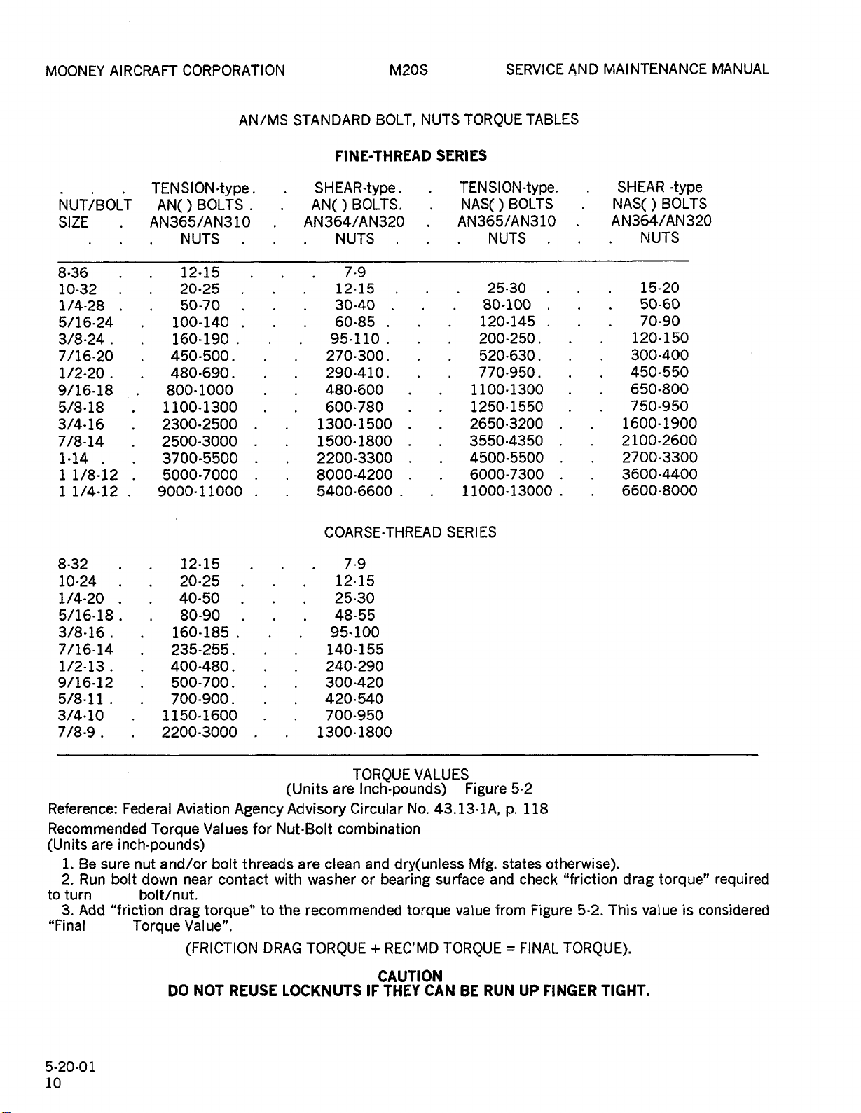
NUT/BOLT
SIZE
8-36
10-32
1/4-28
5/16-24
3/8-24
7/16-20
1/2-20
9/16-18
5/8-18
3/4-16
7/8-14
1´•14
11/8-12
11/4´•12
S
ION
TEN
BOLTS
AN()
AN365/AN310
NUTS
12´•15
20-25
50-70
100-140
160-190
450-500.
480-690.
800´•1000
1100-1300
2300-2500
2500-3000
3700´•5500
5000´•7000
9000´•11000
-type
AN/MS
STANDARD
FINE-THREAD
SHEAR´•type
AN()
AN364/AN320
NUTS
12-15
30-40
60-85
95-110
270´•300.
290-410.
480-600
600-780
1300-1500
1500-
2200-3300
8000-4200
5400-6600
BOLTS.
7-9
1800
BOLT,
NUTS
SERIES
TORQUE
SION
TEN
NASC)
AN365/AN310
11000-13000
BOLTS
NUTS
25-30
80-100
120-145
200-250
520´•630.
770-950.
1100-1300
1250´•1550
2650´•3200
3550´•4350
4500-5500
6000-7300
TABLES
´•type.
SMEAR
NAS()
´•type
BOLTS
AN364/AN320
NUTS
15-20
50-60
70-90
120-150
300´•400
450-550
650-800
750-950
1600-1900
2100´•2600
2700-3300
3600-4400
6600-8000
8-32
10´•24
1/4-20
5/16-18
3/8-16
7/16-14
1/2-13
9/16-12
5/8-11.
3/4´•10
7/8-9
Reference:
Recommended
i.
2.
turn
3.
Be
Run
Add
are
sure
bolt
"friction
(Units
to
"Final
12´•15
20-25
40´•50
80-90
160´•185
235-255.
400-480.
500-700.
700-900.
1150´•1600
2200-3000
Federal
Aviation
Torque
inch´•pounds)
and/or
nut
down
bolt/nut.
near
drag
Torque
Value".
(FRICTION
Values
bolt
contact
torque"
Agency
for
threads
to
DRAG
(Units
Advisory
Nut´•Bolt
are
with
the
COARSE-THREAD
7-9
12-15
25-30
48-55
95-100
140-155
240-290
300-420
420-540
700-950
1300-1800
TORQUE
are
Inch´•pounds)
Circular
combination
clean
and
washer
recommended
or
TORQUE
VALUES
No.
dry(unless
bearing
torque
REC’MD
SERIES
Figure
43.13´•lA,
Mfg.
surface
value
TORQU.E
and
from
5´•2
p.
states
118
otherwise).
check
Figure
FINAL
"friction
5-2.
This
TORQUE).
drag
value
torque"
is
required
considered
5-20-01
10
DO
NOT
REUSE
LOCKNUTS
CAUTION
IF
THEY
CAN
BE
RUN
UP
FINGER
TIGHT.
SERVICE
OLDWILLWAYNE
MAINTENANCE
AND
MANUAL
M20S
MOONEY
AIRCRAFT
CORPORATION
530-02
Aircraft
addition
the
100-hour
to
status
Regulations.
Airplane
Book,
Airworthiness
Engine
License
and
5-20-03
Prior
and/or
engine,
Then
recommended
record
engine
Flight
Propeller
Service
(if
Mooney
to
a
25
wash
perform
of
runup,
all
compression
and
abnormalities,
after
test
flight
5-20-04
one
The,
time,
inspection
condition,
the
require
including
Airplane
removal
components;
lubrication
all
should
be
maladjustment
first
the
After
operation,
recommended
1.
Visually
Inspect
operating
Inspect
exhaust
or
Inspect
Inspect
scratches
Inspect
Inspect
Inspect
Inspect
10.
Inspect
remove
of
on
evidence
and
and
etc.
cowling;
2.
been
operation
3.
oil
4.
installed
5.
external
to
6.
cracks,
7.
freeplay,
8.
obstructions.
9.
screws,
AIRCRAFT
examining
of
compliance
This
Manual,
Log
Certificate,
Information,
applicable),
service
ENGINE
scheduled
after
hours
down
an
engine
the
in
malfunctions
complete
check.
perform
completing
FIRST
25-hour
the
of
propeller,
Flight
of
however,
service
extensive
which
25
hours
refer
engine
inspect
cowling.
clean
and
alternate
engine
leaks.
security
engine.
fuselage,
dents.
and
windshields
scratches.
control
damage.
pitot
aircraft
service
and
and
annual
aircrafi
the
with
review
Aircraff
Book,
Weight
FAA
documents.
FUNCTIONAL
100-hour
installation
the
engine
runup
Airplane
and
To
a
verify
a
the
25-HOURS
inspection
a
prefiight
Manual.
all
access
it
should
requirements.
enough
might
of
to
a
paragraph
inspection.
propeller,
induction
under
air
door.
compartment
and
wing
of
damage.
systems
static
and
exterior
batteries.
INSPECTION
FILE
inspections
current
includes
Log
Registration
Aircraft
Airworthiness
or
of
and
in
accord
Flight
abnormalities.
differential
correction
second
inspection.
engine,
inspection
The
panels
include
detect
to
jeopardize
or
new
spinner,
air
dusty
for
condition
and
Pay
and
windows
for
systems
for
proper,
a
Federal
inspection
Book,
Engine
Balance
Radio
CHECK
annual
or
new
engine
components.
with
Manual.
(hot
malfunctions
of
engine
INSPECTION
consists
and
runup
aircraft
as
inspection
or
disassembly
completion
The
anydmage
night
ovemauled
5-20-05
and
if
filter
conditions.
evidence
of
empennage
particular
for
binding,
for
security
cover,
review
Aviation
of
Certificate,
Record,
Station
Directives,
inspection,
ovemauled
procedure
Make
After
engine)
and
visual
of
a
general
outlined
does
inspection
safety.
engine
for
engine
aircraft
Check
of
fuel,
equipment
attention
crazing,
excessive
possible
of
bolts,
the
Log
the
not
the
has
for
in
of
a
a
in
of
of
or
5-20-05
60-hour
The
25-hour
inspection
hours
newly
of
overhauled
inspection
filter.
and
1.
Engine.
for
A.
B.
C.
oil
Drain
Remove
and
Remove
data
strainer
cartridge.
Remove
D.
E.
Service
,,d
amount
F.
G.
Inspect
Inspect
evidence
security.
H.
Inspect
I.
Inspect
around
J.
Inspect
cylinders,
movement,
K.
Drain
L.
connections
Visually
M.
Visually
operation
71-62-00).
N.
2´•
Propeller.
A.
Inspect
mounts
Inspect
isolator
condition,
B.
Inspect
discrepancy
Cabin.
3.
A.
Inspect
systems
B.
Inspect
operation
C.
Inspect
proper
operation,
D.
Lights
glareshield,
lights.
E.
F.
4.
Landing
A.
B.
Inspect
pump
Inspect
Inspect
static
boost
attachments
inflation.
aircraft
-50-HOUR
inspection
inspection,
doors,
operating
including
(Refer
change
engine
and
plug.
and
engine
of
lubricating
engine
of
leakage,
spark
cylinders
baffles
engine
and
security.
and
clean
inspect
evidence
and
alternate-air
of
engine
for
propeller
looseness,
blades
prior
for
proper
trim
travel.
and
cabin
Inspect
position,
fuel
for
proper
Inspect
installed).
(if
Gear.
tires
shock
weight.
includes
plus
panels,
time,
engine
replacement
to
frequency)
oil
sump
clean
Safety
and
replace
clean
oil
intake
looseness
plug
for
freedom
and
controls
fuel
fuel
inspect
mount
security
and/or
for
to
next
brake
operation
system
and
and
sealing.
cabin
anti-collision
selector
operation.
oxygen
for
discs
INSPECTION
the
or
fairings.
a
new,
should
engine
suction
strainer
wire
fuel
injector
with
sump
oil.
and
elbows
for
evidence
secure
from
for
strainer.
and
of
leakage
induction
door
bolts
and
and
hub
oil
nicks
flight.
and
parking
and
and
baggage
interior,
valve,
system,
blisters,
cuts,
for
-(Repetitive)
all
requirements
necessary
After
re-manufactured,
be
given
the
of
manufacturer’s
oil
lubricating
strainer;
plug.
full-flow
the
fuel
proper
exhaust
or
damage.
and
shielding
of
overheating.
anchorage,
cracks.
full
travel,
lines
air
(refer
or
damage.
system;
firewall
far
to
oil
condition.
spinner
leakage.
cracks.
and
brake
fluid
level.
indicator
doors
instrument
and
landing
gascolator,
plumbing
wear
proper
removal
the
50-hour
a
reinstall
oil
strainer.
type,
systems
nuts
close
freedom
security
paragraph
for
general
Repair
for
for
damage,
and
and
extension
of
first
service
filter
grade,
check
Lord
any
control
free
panel,
and
and
proper
the
of
25
or
oil
for
for
fit
of
of
taxi
at
5-20-02
MOONEY
OLDWILLWAYNE
AIRCRAFT
CORPORATION
M20S
SERVICE
AND
MAINTENANCE
MANUAL
C.
Inspect
disc
wear,
installation.
5.
Wings.
A.
Inspect
B.
C.
D.
6.
Fuselage
A.
B.
C.
7.
See
Inspect
Inspect
operation.
of
Lubricate
Inspect
proper
Lubricate
Check
bellcranks
proper
evidence
necessary.
damage,
necessary,
inspections
5-20-06
(RefertoPig.
The
100-hour
searching
for
the
exterior,
all
fuselage,
plates,
bearing
fuselage
inspection
AIC
of
cover
and
to
replacements
testing
when
of
components
applicable.
Directives,
applicable
Bulletins
conformance
aircraft.
Recommended
requirements
EN61NE
1.
remove
engine
an
recommended
engine
and
engine
Operators
and
abnormalities,
test
after
set-up.
A.
Complete
compression
rev.):
necessary.
leakage.
for
clean
full-flow
and
obstruction.
clean
B.
Inspect
condition
C.
Drain
oil
safety.
Inspect
suction
oil
hydraulic
warpage,
surfaces
ailerons,
for
damage
flaps
binding.
and
stabilizer,
operation
Trim
Section
and
component
-100-HOUR
ANNUAL
5-3)
(or
inspection
engine
wing,
and
locations
mating
(See
Airworthiness
Mooney
and
FAA
to
100-hour/annual
outlined
are
INSPECTION.
cowling
engine
runup
in
Manual.
the
100-hour/annual
check
and
engine
oil
and
security.
engine
screens;
filter
cartridge;
Check
Safety
brake
hydraulic
and
tips
aileron
and
proper
and
attachments
flaps,
observe
per
Cycle
controls
Empennage.
elevators,
and
controls
System
5-20-07
proper
per
for
proper
for
any
service
INSPECTION
INSPECTIONS)
annual)
of
includes
and
and
fairings
inspection
entire
the
the
engine
empennage
at
all
(including
points).
Section
is
Comply
or
Instructions.
to
be
Directives
Vendor
5-10-01)
included
with
Specification
in
the
Prior
and
propeller
compartmentdown.
in
accord
TCM
To
perform
(Ref.
gap
cooler.
verify
a
for
oil
with
Engine
correction
a
differential
TCM
or
replace
evidence
Inspect
sump;
reinstall
second
replace
crank
wire
case
oil
filter
installation.
system
fluid
for
for
level
damage.
attachments,
operation,
for
travel
Section
and
fin,
attachment.
Section
operation,
repetitive
guides.
is
aircraft.
thorough
compartment,
inspection
systems
wing
attach,
and
Operating
at
applicable
Notes
mandatory
Check
2A3
for
and
special
following
to
the
paragraphs:
spinner.
100
Then
hour
Maintenance
of
runup
inspection
(hot
SE
M84-15
spark
of
oil
and
remove,
and
safety.
with
new
breather
disc
or
and
proper
damage
and
5-20-07,
rudder
5-20´•07,
50
for
a
thorough,
Preparation
cleaning
removal
doors,
hinge,
empennage
and
special
this
interval,
(AD’s),
Service
aircraft
for
M20S
Model
inspection
inspection,
Wash
perform
procedure
malfunctions
and
engine
engine)
current
or
plugs,
fuel
and
fuel
hoses
inspect
Remove
cartridge
lines
pad
and
and
any
for
hour
limit
FAA
and
and
flight
oil
and
for
grade,
security
Strainer.
check
and
heating
exhaust/manifold
if
manifolds
500
security
connections
if
synchronization
points
Inspect
cam
excessive
inspect
manual.
holes,
Inspect
broken
of
vacuum
and
damage
isolation
operation,
housing
attachment.
Service
71-00-50.
ignition
terminals,
system
for
solution
and
damaged
if
damage
cracks,
belts,connections
21-58-00.
proper
slip-joints
D.
and
E.
F.
Remove
fuel
BOOST
G.
H.
Remove
Hrs).
I.
follower
J.
Inspect
deformation,
K.
damage.
L.
M.
Cablecraft
life
of
N.
O.
P.
Inspect
obstruction.
Q.
Inspect
for
R.
S.
Inspect
T.
Inspect
torque.
U.
Inspect
Refill
quantity
inspect
and
condition
Inspect
system
PUMP
Inspect
air
(SEE
Inspect
and
in
Check
for
condition,
distributor
oil
magneto
Repair
cylinders
fins.
Inspect
Inspect
pumps
Inspect
and
mounts
Insped
full
travel,
swage
the
control
Inspect
information
Inspect
harness
and
for
condition
neutralize
to
evidence
area.
is
found.
Inspect
distortion
for
cracks,
fuel
and
fuel
with
air
connections
Para.
and
alternate
induction
of
inspect
"ON".
clean
oil
sump
lubricating
injector,
fuel
and
lines
mixture
ducting
for
5-20-06,1,Q,
Inspect
engine
all
systems
operation.
the
magnetos
(timing
to
clearance,
block
for
felt
for
proper
breaker
from
TCM/magneto
per
or
replace
baffles
for
accessory
hoses,
tubular
corrosion;
for
engine
at
control
lubricate
or
engine
battery
for
condition,
bumed
batteries,
Flush
exhaust
for
for
and
burned
baffle
firewall
security
and
proper
the
HEAD
NOTE
cables
cable.
for
for
IO´•550-G
cables,
chaffed
or
battery
and
battery
corrosive
system
of
leakage.
components,
sealant.
engine
inspect
corrosion.
Replaceorrepair
exhaust
and
looseness.
airconditioning
(if
installed).
exhaust
nuts,
couplings,
studs,
deformation,
with
oil.
fuel
line
noules
gascolator
and
connedions:
control
and
connections
leaks.
and
induction
air
door
all
air
system
for
engine);
lubrication,
close
and
and
anchorage,
fit
erosion
compartment.
secure
paint
case,
and
starter,
and
mount
all
condition.
propeller
connedion
tube
lubricated
are
DO
NOT
control
proper
cable.
set-up.
engine
electrical
secure
insulation.
mount
mount
action,
for
Replace
muffler
stacks
bolts,
for
compressor
Reference
etc.
seals,
leaks
the
proper
connections
TCM
(Ref
strainer,
at
IDLE
Leak
engine
R8S
air
and
air
filter
for
below).
ducting
leaks.
grounding
inspect
internal
cracks.
and
At
maintenance
if
required.
around
and
cracked
fittings
for
bolts
and
controls
(security)
and
REMOVE
and
wiring,
anchorage,
areas,
Inspect
areas
if
necessary.
cracks,
if
any
burned
For
damage
clamps
and
type,
SE).
reinstall
pressure
CUTOFF
in
cabin
check
exhaust
(replace
magnet
and
and
magneto
timing.
Inspect
remove
500
hours
cracks,
cylinders.
and
altemator,
for
security
cracks,
rubber
for
free
cable
of
security
the
for
seals
TCM
(See
Section
and
loose
and
vent
tube
blast
soda
with
looseness
or
repair
internal
areas,
installation,
SECTION
and
and
security.
for
all
at
for
of
5-20-06
12
SERVICE
OLDWILLWAYNE
AND
MAINTENANCE
MANUAL
M20S
MOONEY
AIRCRAFT
CORPORATION
V.
for
indication.
security
Inspect
operation,
2.
PROPELLER
A.
Remove
B.
Inspect
C.
Inspect
and
5,6.
D.
Inspect
blades
and
flight,
E.
Inspect
F.
G.
LANDING
3.
A.
Inspect
Inspect
hub
Inspect
condition.
propeller
necessary
INSPECTION.
slippage
approved,
Always
Retraction
removed
B.
Inspect
misalignment,
condition
at
250
warpage
leakage,
C.
D.
E.
F.
of
hour
Inspect
(Ref.
Inspect
inspect
dents,
Inspect
engagement
Check
G.
landing
landing
Jack
for
Inspect
or
H.
aircraft,
the
I.
Inspect
broken
Maximum
gear
Inspect
damage
following
nose
roll
assembly
heat
on
J.
Inspect
adjustment,
K.
Inspect
L.
Inspect
bellcranks,
distortion,
lubrication.
M.
Inspect
mounting,
and
damage.
re-install
and
condition,
INSPECTION.
spinner
securityofpropeller
hub
studs/nuts/bolts
damage.
hub
for
components
cracks
Anti-ice
spinner
spinner
fit..
GEAR
tires
excessive
if
necessary.
least
at
wheels
corrosion
seals
and
for
checks
cylinder
for
snug
and
tire(s),
run
felt
inteluals.
Cycle
andlor
brakes
Section
hydraulic
hydraulic
cracks
parking
and
release.
shock
assemblies.
leg
Landing
SECTION
(Ref.
recommended
as
inspections:
nose
gear
retraction
gear
pins.
allowable
is
1/32
inch
treated
nose
landing
wheel
alignment,
main
gear
landing
pivots
and
misalignment,
landing
cleanliness,
Check
motor
cowling.
proper
not
(if
Reference
nicks.
and
for
boots
and
bulkhead
bulkhead
3
rear
and
RETRACTION
proper
wear.
CAUTION
5
complete
after
replaced,
aircraft.
for
and
and
bearings;
for
disc
32-40-04).
reservoir
brake
chafing,
brake
disc
gap
(Ref.
Gear
components
cleanliness
for
tube
NOTE
towing
dent.
steering
corrosion,
cleanliness
for
gear
bearings
corrosion,
gear
and
indication
operation
opening
already
installation.
SECTION
for
Repair
security.
bulkhead.
inflation,
Replace
any
before
cracks,
bolt
and
for
lines
kinks
system
on
32-81-00)
32-82-00)
in
paragraph
bungees
damage
No
repair
gear
and
retraction
for
actuator
Check
cowl
and
removed).
for
proper
damage
and
prior
for
cracks
for
snug
fl
Use
cuts,
with
Landing
tire
has
flying
failure.
re-pack
pad
wear,
and
main
fluid
and
security.
for
for
and
for
on
is
hoses
and
allowed
proper
components.
mechanism
lubrication.
and
damage.
wear,
cleanliness,
for
security
of
overheating
and
brush
flap’s
position
torque,
61-00-20,
leaks,
to
ne~ct
and
between
shims
SYSTEIVI
blisters,
new,
Gear
been
the
distortion,
Inspect
bearings
and
disc
level.
proper
nose
hard
any
7-10-00,
damage.
sheared
leg
linkage,
damage,
and
wear.
for
for
as
of
Perform
N.
Section32-30-01.
4.
A.
seepage
B.
seepage
C.
and
water
D.
E.
selection,
OFF
F.
sediment,
G.
mounting,
condition
and
Check
(1)
"T
ing"
High
reading
H.
security
electrical
i.
security,
fuel
needed
5.
EXTERIOR
A.
damage,
FUEL
Inspect
and
Drain
is
Inspect
Inspect
Inspect
position.
Inspect
water
Inspect
into
boost
(mixture
Inspect
of
connections.
Inspect
and
filler
(Reference
Inspect
SYSTEM
evident.
contamination.
smooth
adequate
electric
line
operation
mounting
cap
loose
oilcans(stretched
deteriorated
B.
crazing,
installation.
C.
damage,
cracks,
freedom
weight
D.
Check
wear.
E.
loose
cracks,
attachment
operation,
F.
corrosion,
G.
lubrication
52-11-00
H.
paint.
Inspect
scratches,
Inspect
loose
condition
of
operation,
attachment.
Inspect
for
Inspect
or
popped
condition
of
manually
Inspect
nicks,
Inspect
and
for
rigging
Inspect
compartment
condition
i.
Inspect
J.
Inspect
K.
Inspect
condition
and
ventilating
and
for
adjustment
security,
condition
and
condition
33-43-00
location.
landing
INSPECTION.
fuel
tank
stain.
tank
and
fuel
tank
fuel-tank
fuel
selector
operation
gascolator
and
other
electric
of
fuel
fuel
condition
boost
fuel
and
wiring
boost
withacalibrated
full
RICH,
quantity
and
tank
O’rings
Section
INSPECTION.
fuselage
and
skins),
windshields
condition
wings,
or
flaps,
popped
of
free-play,
Speed
proper
cabin
Brake
operation.
empennage
rivets,
and
balance
and
door
dents,
hinge
cabin
proper
procedures.
baggage
for
damage,
to
door
operation
of
cargo
restraintsniedowns.
system
landing
proper
Decals/Placards
operational
gear
exterior
inspect
drains
vents
pump
should
for
for
valve
and
for
leakage;
contamination.
pump
pressure,
electrical
for
result
throttle-IDLE).
gauges
condition
filler
port
of
servicing
for
condition
28-00-01).
exterior
surfaces
popped
scratches,
and
of
sealant,
and
ailerons
rivets,
attaching
cartridges
for
free-play,
lubrication
weights
electrically.
door
and
security
door
lock
engagement.
door
corrosion,
frame
of
door
drain
and
taxi
adjustme
procedures.
evidence
for
tank
leakage,
obstruction.
for
leakage
any
inspect
for
leaks,
switch
connections.
proper
fuel
pressure
in
transmitters
and
of
for
cleanliness,
placards.
and
rivets,
windows
and
dents,
points,
travel,
for
(Ref.
27-96-01)
corrosion,
dents,
of
and
frames
and
mechanism
and
warpage,
and
locking
for
line
lights
nt.
condition
for
check
interior
sediment,
proper
security
operation,
operation
15
a
wiring
replace
for
corrosion,
cracks
for
security
for
corrosion,
scratches,
lubrication,
and
damage
scratches,
hinge
freedom
for
lubrication.
See
door
mechanism
obstruction.
for
See
per
fuel
of
when
tank
when
for
sump
gauge.
P.S.I.
for
and
cap
Inspect
dents,
and
cracks,
balance
damage,
points,
damage,
for
Section
baggage
hinge
seals,
security,
Section
and
5-20-06
in
of
by
if
of
or
of
13
MOONEY
OLDWILLWAYNE
AIRCRAFT
CORPORATION
M20S
SERVICE
AND
MAINTENANCE
MANUAL
L.
Inspect
Inspect
extremities
and
trailing
high
voltage/am
6.
INTERIOR
A.
cleanliness
condition
structure
mechanism
brackets
Inspect
B.
security
C.
restrict
35
location.
panels
and
D.
Inspect
this
of
E.
7.
INTERNAL
A.
B.
safetying,
control
Open
and
Inspect
(interior
adequately
C.
Inspect
D.
damage
\(Reference
specific
E.
F.
G.
and
Inspect
Inspect
and
Inspect
evidence
cracks,
lines
chaffing
Seal
H.
corrosion,
I.
Inspect
hardware
8.
FLIGHT
A.
travel,
Inspect
proper
mounting,
surface
movement.
All
inspected
B.
Inspect
lubrication,
all
bearings,
downspn’ng
mounting
C.
Inspect
lubrication,
static
wicks,
(vertical
edges
and
and
operation
for
lubrication.
Inspect
for
cleanliness,
of
attachment,
Inspect
movements.
O~gen
S
8
M
Inspect
inspection
fairings
wing
and
ABS
side
accomplish
forward
Inspect
(interior
Mooney
procedures
wing
of
damage
corrosion.
electrical
air
ducts
and
de-bonding.
all
receptacles
environment
Inspect
and
evidence
empennage
for
corrosion.
CONTROL
control
rigging,
proper
movement
control
flight
to
are
elevator
rigging,
pivots,
eyes,
and
proper
aileron
rigging,
exterior
wing
8
hon’zontal),
for
signs
damage.
INSPECTION.
seats,
seat
mounting
cracks,
safety
for
belts,
loose
system
manual.
Decals/Placards
INSPECTION.
as
required.
attaching
evidence
panels/carpet
this
side
tubular
side
panels
Service
required
ribs
and
wing
spars
for
security,
NOTE
with
wing
interior
of
INSPECTION.
column
free-play,
lubrication
with
CAUTION
components
that
verify
free
of
system
travel,
bellcranks,&
cable
pulley
relation
system
travel,
for
signs
antennas,
tips,
of
burned/charred
tracks,
security.
of
position
deformation,
hamess
condition,
equipment,
(if
installed)
doors
bolts
of
damage
and
will
inspection).
of
firewall
structure
will
Bulletin
annually).
and
stringers
corrosion.
for
wiring,
fuel,
damage,
and
plugs
Dow
Coming
for
fuel
leakage.
attachment
and
and
proper
relation
all
moisture
obstructions.
for
stop
adjustment,
and
to
control
for
adjustment,
stop
of
lightning
and
and
Inspect
locks.
latch
etc.
for
remove
for
require
for
for
require
damage,
oil
outside
foreign
control
binding,
direction
to
should
damage,
hinges
fittings,
movement.
damage,
empennage
propeller
or
upholstery
seats
Inspect
corrosion
and
attaching
operation
that
CHAPTER
per
condition
proper
and
corrosion
removal
damage.
corrosion
removal).
M20-208A
for
cracks
distortion,
and
hydraulic
interference,
cabin
#4.
material,
brackets
wheels
security
of
control
be
drain
holes
corrosion,
condition
wear
security
corrosion,
condition
strikes.
tips
other
for
for
seat
and
and
might
and
access
torque
and
for
and
and
for
full
control
wheel
of
on
of
of
to
of
security
D.
E.
guide
F.
All
with
bellcranks,
Inspect
and
relation
wheel
Inspect
proper
trim
threads
Check
for
position
control
the
rigging,
of
travel.
adjustment,
joints
blocks
27-42-00
n’gging,
push-pull
and
aircraft
hinges,
bolt
lubrication,
pivots
proper
movement
"OSe
a"d
rigging,
universal
actuator
and
SECTION
maintenance.
tubes
flap
actuator,
bellcranks
lubn’cation.
7)
Some
wrapped
ShowS
Trim
Y9265
signs
poiyurethane
tubes,
abrading
MAX.
TUBE
diameter
9.
condition
filter
Check
lights
reduction.
INSTRUMENT/AVIONICS
A.
Inspect
and
B.
Clean
on
vacuum
C.
Inspect
operation
or
vacuum
D.
Inspect
indication,range
indicator
marks,
E.
markings,
and
security
Inspect
compensation,
discoloration.
and
after
any
Degaussing
F.
Inspect
G.
Inspect
structure
H.
Inspect
will
Instruction
proper
and
markers.
of
shock
compass
Se"ice
markings,
freedom
reference
condition
with
8
security.
and
proper
rudder
rod-end
to
toe-brake
stabilizer
control
for
flap
condition
bearings,
control
free-play
for
lubrication,
for
looseness
for
system
system
wheel
travel,
indicator
for
tubes,
hinges
pivots
rigging
inspections
jacked
and
landing
elevator
wrapped.
VVEAR-.0O7
proper
and
security
Swing
tubular
not
synchronization
and
Avionics
trim
at
bulkhead
of
wear,
without
bulkhead
all
instrument
connections.
inspect
regulator.
vacuum
of
gage.
all
instruments
and
cracked
of
installation.
compass
compass
new
equipment
structure
compensate
M20-95.
altimeter
pointer
flight
panel
mounts,
condition
tape,
See
regulator
high-and
of
Equipment
and
relation
movement.
pedals
trim
control
shaft
and
and
Electric
for
rigging
and
stop
proper
flap
for
corrosion,
NOTE
and
gear
NOTE
tubes
penetrations.
re-wrap
tape
which
grommet
SE
in.
wall
wiring
vacuum
limit
markings,
or
mounting,
within
for
scale
readings,
of
for
freedom
of
ground
rod
end
control
to
for
damage,
of
hinges,
bolt
link
and
proper
system
stop
for
smooth
good
linkage
excessive
or
Trim
System
actuator,
adjustment.
operation.
rods,
should
leveled
retracted.
have
poly
tube
with
(1/2
tape
show
should
M20-185.
thickness
INSPECTION.
and
filter.
at
vacuum
low-vacuum
for
proper
loose
glass,
for
proper
liquid
annual
at
has
been
be
may
100.
error,
barometric
security
from
straps.
for
proper
bearings,
movement.
corrosion,
bellcranks,
security
Check
nuts
rudder
for
for
for
security
proper
operation,
working
for
corrosion,
weal:
bearing
push/pull
Check
Inspect
interconnects,
security,
be
made
Section
(Per
tape
If
tape
2"
wide
overlap).
signs
be
.014
or
plumbing
Replace
garter
manifold.
warning
pointel:
condition
slippage
lighting,
leakage
inspection
installed.
necessary
See
Mooney
discolored
setting
scale
of
mounting,
interference
operation
link
and
free
and
order,
See
and
of
in.
for
of
and
if
knob
with
5-20-06
14
SERVICE
OLDWILLWAYNE
i.
Inspect
obvious
lines
security
leaks.
J.
for
K.
damage
Inspect
of
Inspect
aerodynamic
for
lines
attachment.
attemate
freedom
for
10.
ELECTRICAL
Check
A.
B.
Check
Check
C.
lighter.
D.
Check
E.
Checkoperation
Check
lights.
dropouts.
F.
G.
H.
Check
only)
Check
Check
duration
MAINTENANCE
AND
Avionics
defects,
or
head
pitot
cracks,
bends,
static
dents,
attachment.
static
smoothness
cracks,
Drain
system
pressure
of
valve
movement.
FUNCTIONAL
operation
operationoflanding
operation
operation
rheostat
operation
observing
by
operation
operation
Antennas,
for
kinks,
Drain
ports
at
port
dents,
and
source
of
navigation
of
of
anticollision
of
travel
for
of
pitot
ammeter
of
cluster
of
fuel
MANUAL
wiring,
obstruction;
port
proper
system
for
installations.
kinks,
inspect
located
TEST.
dome
instrument
dimming
head
gauge,
gauges.
bend
and
obstruction
and
for
on
lights.
taxi
lights.
lights
lights,
needle
shielding
radius
inspect
security
leaks.
flight
and
and
without
heater
flucuation,
for
inspect
and
for
and
Inspect
Check
panel
cigar
placard
any
(short
M20S
of
MOONEY
Check
i.
switch.
J.
solenoid.
K.
(See
(See
L.
Section
Section
Check
Check
During
operation
operation
operation
24-36-00
32-00-00).
post
setting/operation
Check
M.
Push
switch
illumination
fluctuation
N.
Inspect
proper
covered
attachment
Flight
malfunctions
aircraft
V~ng
between
installation
11.
MISCELLANEOUS/OPTIONAL
A.
12~
POST
test
log
access
Component
"ON",
during
Inspect
previous
by
and
INSPECTION
the
book.
model
locations
operation
(BLUE
batteries,
any
obvious
and
covers
year
of
of
of
inspection
of
stall
warning
of
observe
light).
action
cycle
connection
corrosion
other
paragraphs
damage
aircraft
abnormalities.
may
aircraft.
remain
AIRCRAFT
annunciator
ignition
landing
32-60-00)
"Prop
prop
Observe
of
and
installed
FLIGHT
to
verify
Make
vary
basically
CORPORATION
light
switch,
gear
and
flight,
horn.
De-ice"
de-ice
timer.
3
battery
cleanliness.
EQUIPMENT
for
proper
malfunctions.
or
TEST.
correction
proper
to
unchanged.
press-to-test
and
position
warning
check
installed).
(if
annunciator
ammeter
areas
equipment
operation,
entries
some
degree
starter
lights
horn
proper
of
for
for
for
not
all
in
5-20-07
ITEM
NUMBER
1
2
Access
See
No
periodic
use
Change
Change
Inspect
Service
REFERENCE
covers
ITEM
Flight
Vacuum
Control
Control
Engine
Vacuum
last
page
Aeroshell
garter
instrument
Stand-by
Letter
ACCESS
DESCRIPTION
Instruments
Vacuum
Turn
Rod
Universal
Bellcranks
of
lubricant
22,
filter
No.
FIGURE
riveted
in
COVER
place
Regulator
Coordinator
Filters--Replaceat
System
Column
End
Adjustments:
Bearing
Bearings
Joints
Cowling
Pumps
section
on
Mobil
on
filters
Vacuum
for
Avionics
28
vacuum
at
Pump
lubrication
or
500
34)
FOR
LOCATION
production
5-3
during
IDENTIFICATION,
Ball
symbol
Products
MIL-G-81322
regulator
hours,
drive
#102000-2.
ONLY.
every
clean
coupling
NOTE
legend.
100
every
every
OF
THE
need
LUBRICATION
If
necessary
hours.
100
hours.
200
hours.
FOLLOWING
removed
be
not
AND
LUBRrCATION
SYMBOL"
\y
W
C
C
0
Q
to
(Refer
COMPONENTS
for
SERVICE
relubricate,
to
Airborne
routine
GUIDE
inspections.
INTERVAL
(HRS)
500
100
100
100
100
100
500
5-20-07
15
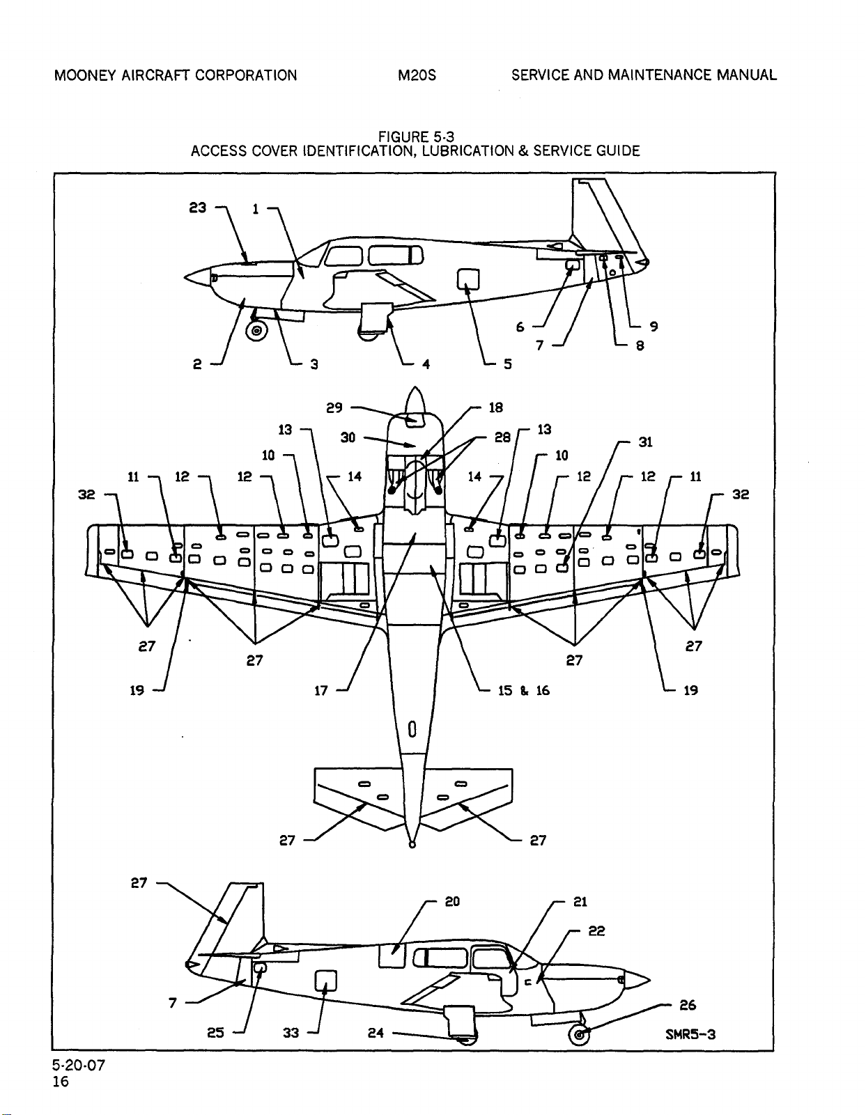
MOONEY
OLDWILLWAYNE
AIRCRAFT
CORPORATION
M20S
SERVICE
AND
MAINTENANCE
MANUAL
ACCESS
23
7
COVER
1
FIGURE
IDENTIFICATION,
5-3
LUBRICATION
SERVICE
GUIDE
I
1
2
L
3
L
4
29
13
30
10
11
32
12
12
14
I’
14
’I
6
7
L
5
18
28
13
10
12
I
I I I
L
9
L
8
31
12
11
32
r
o
0
27
19
o
000
oooo
27
000
C)
Q
o
o
ooo,.
00
000
o
0
27
27
17
c
o
o
o
15616
19
27 27
27
20
21
22
5-20´•07
16
CI
7
25
33
24
---~J
1
26
SMR5-3
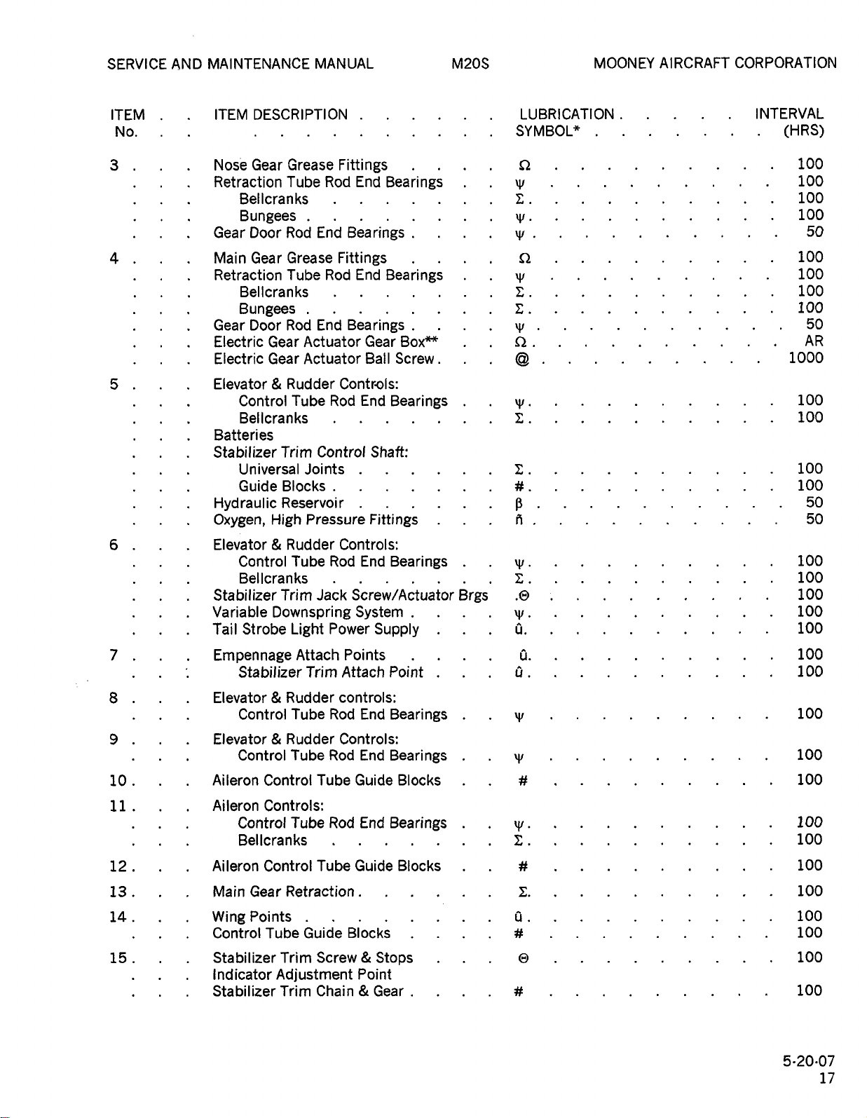
SERVICE
OLDWILLWAYNE
AND
MAINTENANCE
MANUAL
M20S
MOONEY
AIRCRAFT
CORPORATION
ITEM
No.
3
4
5
6
7
DESCRIPTION
ITEM
Gear
Nose
Retraction
Bellcranks
Bungees
Gear
Door
Gear
Main
Retraction
Bellcranks
Bungees
Gear
Door
Electric
Electric
Elevator
Gear
Gear
Control
Bellcranks
Batteri
es
Stabilizer
Universal
Guide
Hydraulic
Oxygen,
Elevator
Stabilizer
Variable
Tail
High
Control
Bellcranhs
Downspring
Strobe
Empennage
Stabilizer
Grease
Tube
Rod
Grease
Tube
Rod
Actuator
Actuator
Rudder
Tube
Trim
Joints
Blocks
Reservoir
Pressure
Rudder
Tube
Trim
Jack
Light
Attach
Trim
Fittings
Rod
End
Bearings
End
Bearings
Fittings
End
Rod
End
Bearings
Bearings
Gear
Ball
Box"
Screw.
Contr~[s:
Rod
End
Bearings
Control
Shaft:
Fittings
Controls:
End
Rod
Bearings
Screw/Actuator
System
Power
Points
Attach
Supply
Point
Brgs’
LUBRICATION.
SYMBOL"
Q
\y
\y.
yl
Q
\y
C.
C.
\V
ZZ
yl.
C~.
P
A
\y.
.O
\y.
0.
0.
Li.
INTERVAL
(HRS)
100
100
100
100
50
100
100
100
100
50
AR
1000
100
100
100
100
50
50
100
100
100
100
100
100
100
8
9
10
12
13
14
15
11
Elevator
Control
Elevator
Control
Aileron
Aiieron
Control
Controls:
Control
Bellcranks
Aileron
Main
Control
Gear
WingPoints
Control
Stabilizer
Indicator
Stabilizer
Tube
Rudder
Rod
Tube
Rudder
Tube
Rod
Tube
Tube
Rod
Tube
Retraction
Guide
Screw
Trim
Adjustment
Chain
Trim
controls:
End
Controls:
End
Guide
End
Guide
Blocks
Point
Bearings
Bearings
Blocks
Bearings
Blocks
Stops
Gear
y,
W.
y,
Q.
100
100
100
100
100
100
C.
0
100
100
100
100
100
5´•20´•07
17

MOONEY
OLDWILLWAYNE
AIRCRAFT
CORPORATION
M20S
SERVICE
AND
MAINTENANCE
MANUAL
ITEM
No.
16
17
18
19.
20.
21
22
23
24
DESCRIPTION
ITEM
Elevator
Control
Bellcranks
Guide
Flap
Electric
Electric
Electric
Gascolator
Control
Control
Control
NLGr
Rudder
Rudder-Aileron
Hyd.
Aileron
Outboard
Baggage
Cabin
Engine
Radios
Engine
Oil
Wheels
Wheel
Tube
Blocks
Indicator
Flap
Flap
Boost
Systems:
Tube
Yoke
Steering
Pedal
Brake
Control
Hinges
Latches.
Lock
Seals
Hold
Open
Door:
Hinges
Latches.
Lock
Seals
Hold-Open
Instruments
Controls
Stick,
Dip
8(
Bea
Brake
Shock
Pressure
Guide
Discs
Rudde;
Rod
Cable
Actuator
Actuator
Controls:
End
Pump
Rod
End
(Lower
Link
Rod
Cross
Shaft
Bungee
Cylinder
Tube
Flap
Stops
Compartment
arm:
Arm.
Oil
Filler
Brakes:
rings
Plates
Pins
Bearings
Gear
Ball
Bearings
Section)
End
Pedal
Rod
End
Door:
Tube
Anchor
Box
Screw
Brgs.
Linkage
Brgs
Bolts
LUBRICATION.
SYMBOL"
C.
C
R
8.
C
\y.
C
5.
C
C.
C.
Q.
C.
C.
a.
b.
C.
C.
a.
W.
V
yl
Q
INTERVAL
(HRS)
100
100
100
100
500
100
50
100
100
100
100
100
100
100
100
100
100
100
100
100
100
100
100
100
100
AR
250
50
50
25
26
27
28
5´•20-07
18
Elevator
Nose
Wheel
Shock
Control
Exhaust
Wheel:
Bea
Surface
Assy
Rudder
Discs
ri
ngs
Hinges
Control
Stops
Q.
Q
C.
a.
100
250
50
100
100
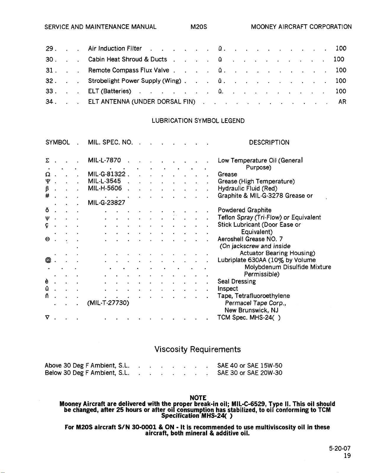
SERVICE
OLDWILLWAYNE
MAINTENANCE
AND
MANUAL
M20S
MOONEY
AIRCRAFT
CORPORATION
29.
30
31
32
33
34.
SYMBOL
C
n.
p
5
\V
c
0
b
Q
ii
V
Air
Induction
Cabin
Remote
Heat
Strobelight
ELT
(Batteries)
ELT
ANTENNA
MIL.
SPEC.
MIL´•L-7870
MIL-G´•81322
MIL-L-3545
MIL´•H-5606
MIL´•G-23827
Filter
Shroud
Compass
Power
NO.
(MIL;27j30)
Ducts
Flux
Supply(Wing)
(UNDER
LUBRICATION
Valve
DORSAL
FIN)
SYMBOL
a.
a
Q
Q
Q.
LEGEND
Low
Temperature
Grease
Grease
(High
Hydraulic
Graphite
Powdered
Teflon
Stick
Q
Spray
Lubricant
Equivalent)
Aeroshell
(On
Grease
jackscrew
Actuator
Lubriplate
Molybdenum
Permissible)
Seal
Dressing
Inspect
Tape,
Tetrafluoroethylene
Permacel
New
Brunswick,
TCM
Spec.
DESCRIPTION
Oil
Purpose)
Temperature)
Fluid
/Red)
MIL-G´•3278
Graphite
(Tri-Flow)
(Door
NO.
and
Bearing
630AA
Tape
(10~
Corp.,
NJ
MHS´•24(
(GeneraJ
Grease
or
Ease
7
inside
Housing)
by
Disulfide
100
100
100
100
100
AR
or
Equivalent
or
Volume
Mixture
Above
Below
30
Deg
30
Deg
Mooney
be
changed,
For
Aircraft
M20S
F
Ambient,
F
Ambient,
aircraft
after
are
S.L.
S.L.
delivered
hours
25
S/N
or
30-0001
Viscosity
with
after
aircraft,
Requirements
the
oil
Specification
ON
both
NOTE
proper
consumption
It
is
mineral
SAE
SAE
break-in
has
MHS-24~
recommended
additive
40
30
MIL-C-6529,
oil;
stabilized,
SAE
or
or
to
oil.
15W-50
SAE
20W-30
to
use
multiviscosity
Type
oil
conforming
II.
This
oil
oil
in
to
should
TCM
these
5-20´•07
19
MOONEY
OLDWILLWAYNE
AIRCRAFT
CORPORATION
M20R
SERVICE
MAINTENANCE
AND
MANUAL
BLANK
5-20-07
20
 Loading...