

Mooney M20M Service Bulletin
alrg~
SUBJECI:
1
MODEUS/N
AFFECTED:
TIME
OF
COMPLIANCE:
INTRODUCTION:
INSTRUCTIONS:
1.
2
3.
4.
5.
6.
7.
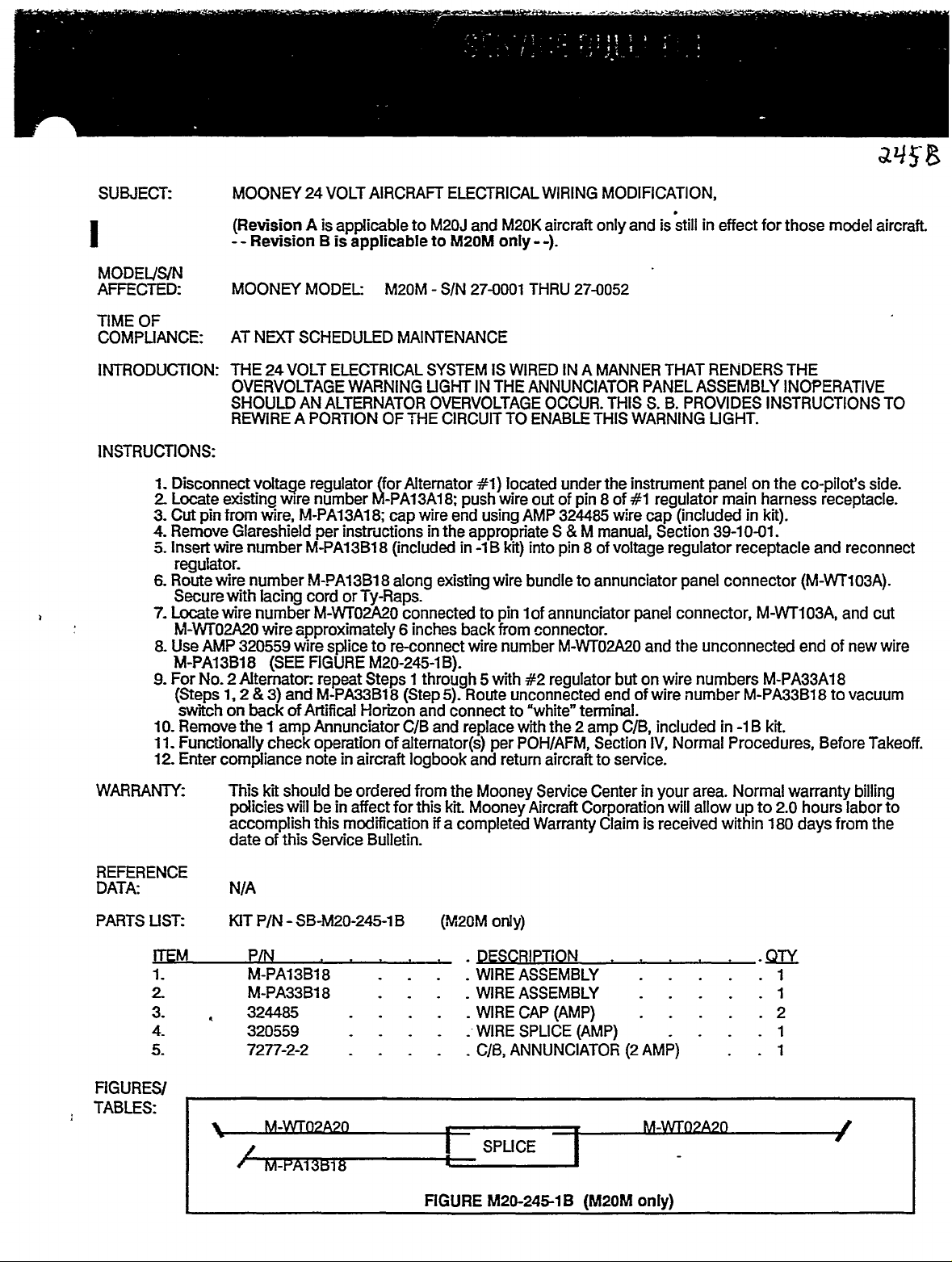
8.
9.
10.
I.
1
12.
MOONEY
(Revision
MOONEY
AT
THE
OVERVOLTAGE
SHOULD
REWIRE
Disconnect
Locate
Cut
Remove
Insert
pin
wire
existino
from
Glareshield
regulator.
wire
Route
Secure
Locate
with
wire
M-V1~02C\20
Use
AMP
M-PA13B18
For
(Steps
switch
Remove
No.
2
1,
on
Functionally
Enter
compliance
24
A
Revision
MODEL:
NDCT
SCHEDULED
VOLT
24
AN
A
PORTION
voltage
wire,
number
number
lacing
regulator
~Mre
M-PA13A18;
M-PA13B18
M-PA13B18
cord
number
wire
320559
wire
nGUREM20-245-1B).
(SEE
Altemator:
2
and
3)
backofArtifical
the
1
amp
check
note
VOLT
AIRCRAFT
is
applicable
B
is
applicable
ELECTRICAL
WARNING
ALTERNATOR
number
per
M-PA13A18;
instructions
or
TyRaps.
M-WT02A20
to
splice
Steps
repeat
M-PA33B18
Horhon
Annunciator
operation
in
aircraft
to
M20J
to
M20M
MAINTENANCE
SYSTEMiSWIRED
LIGHT
OVERVOLTAGE
OF
THE
Altemator
(for
wire
cap
in
(included
along
existing
connected
inches
6
re-connect
1
through
(Step
and
and
C/B
of
altemator(s)
logbook
ELECTRICAL
and
M20M
only--).
27-0001
S/N
IN
THE
CIRCUTT
#1)
wire
push
end
using
the
appropn’ate
-1B
in
wire
to
pin
back
from
wire
with
5
Route
5);
connect
replace
per
and
WIRING
M20K
aircraft
THRU
27-0052
IN
A
ANNUNCIATOR
OCCUR.
ENABLE
TO
iocated
out
AMP
into
kit)
bundletoannunciator
1
of
connector.
number
#2
unconnected
"white"
to
with
POH/AFM,
return
THIS
under
of
pin
324485
S
M
8
pin
annunciator
M-WT02A20
regulator
terminal.
2
the
amp
Section
aircrafttoservice.
MODIFICATION,
stillineffect
and
PANEL
S.
WARNING
instrument
of
#1
wire
cap
voltage
is
THAT
PROVIDES
B.
regulator
(included
Section
regulator
only
MANNER
THIS
the
8
manual,
of
panel
connector,
panel
tile
and
butonwire
endofwire
C/B,
included
Normal
IV,
number
RENDERS
ASSEMBLY
LIGHT.
on
panel
main
in
39-10-01.
receptacle
connector
unconnected
numbers
M-PA33B18
in
-1B
Procedures,
for
those
model
THE
INOPERATIVE
INSTRUCTIONS
the
co-pilot’s
harness
receptacle.
kit).
and
(M-WT103A).
M-WT103A,
end
of
M-PA33A18
kit.
to
Before
side.
reconnect
and
new
vacuum
Takeoff
aircraft.
TO
cut
wire
WARRANIY:
REFERENCE
DATA:
PARTS
FI
LIST:
mM
1.
2
3.
4.
5.
GURESI
TABLES:
This
kit
should
policies
will
accomplish
dateofthis
N/A
KIT
P/N
P~
M-PA~3B18
M-PA33B18
324485
320559
7277-2-2
be
ordered
beinaffect
this
modification
SeM’ce
SB-M20-245-1B
Bulletin.
for
from
this
if
FIGURE
the
Mooney
kit.
MooneyAircraft
a
completed
(M20M
only)
DESCRIPTION
WIRE
WIRE
WIRE
WIRE
C/B,
SPUCE
M20-24518
Service
Corporation
Warranty
ASSEMBLY
ASSEMBLY
CAP
(AMP)
SPLICE
(AMP)
ANNUNCIATOR
-I
(M20M
Center
in
your
will
Claimisreceived
(2
AMP)
only)
area.
allow
Normal
up
within
to
180
.QK
warranty
hourslabor
2.0
days
1
1
2
1
1
from
I
billing
to
the
THIS
SERVICE
BULLETIN
IS
FAA
APPROVED
FOR
ENGINEERING
DESIGN.
SUBJECT:
MODEL
AFFECTED:
TIME
COMPLIANCE.
S/N
OF
INTRODUCTION:
Some
aircraft
Corporation
will
that
recommended
retrofrt
INSTRUCTIONS:
I.
Remove
Service
stamp
Check
2.
per
3.
Remove
on
screw
fairings
action
S
each
modified
be
and
and
on
for
M
the
outboard
(inboard
will
owners
is
offering
that
will
be
replace
Maintenance
fork
the
proper
No.
150.
ABS
8
side)
be
modified
MOONEY
MOONEY
AT
OWNERS
WEIGHT
have
the
in
order
aircraft
the
co-ordinated
the
center
lover
operation
Section
flap
hinge
fairing.
attaching
pn~or
TLS,
MODEL
DISCRETION
ABOVE
expressed
retrofit
for
the
be
procedures
brought
by
Main
Landing
Manual
link)
and
riggingoflanding
32-30-00.
fairings.
The
two
ABS
re-installation.
to
M20M.
INCREASED
M20M.
POUNDS.
3200
desiretoincrease
a
aircraft
back
Product
the
retraction
M)
(S
and
a
(4
inboard
fairing
SIN
of
be
to
No.
ink
each
on
fairings
to
TAKEOFF
27-0001
MANDATORY
BUT
this
Service
flown
at
to
Mooney
Support
truss
Section
150,
"A-2"
stamp
retraction
gear
wing)bydrilling
have
the
inboard
(See
Step4below)
THRU
27-0052
useful
the
Bulletin
the
increased
Aircraft
Department,
assembly,
32-10-00.
after
paint.
screws
wing
flap
WEIGHT
IF
AIRCRAFT
load
of
to
accomplish
takeoff
Corporation
telephone
520024501
P/N
The
out
after
the
system
attaching
hinge
RETROFIT
IS
M20M
the
weight
for-the
truss
new
replacement
rivets
them
to
aluminum
arm
TO
this.
(512)
(UH)
will
on
the
BE
aircraft.
There
of
3368
retrofit.
896-6000.
be
fairing
fuselage
FLOWN
are
pounds.
Scheduling
and
-502
identified
of
retraction
flanges
fairing.
AT
Mooney
several
(R/H)
and
belly
All
ABS
A
Aircraft
It
by
truss
fairing
TAKEOFF
areas
is
of
the
M20M
per
"A-2"
an
assembly
side
the
and
hinge
flap
metal
rivet
one
1
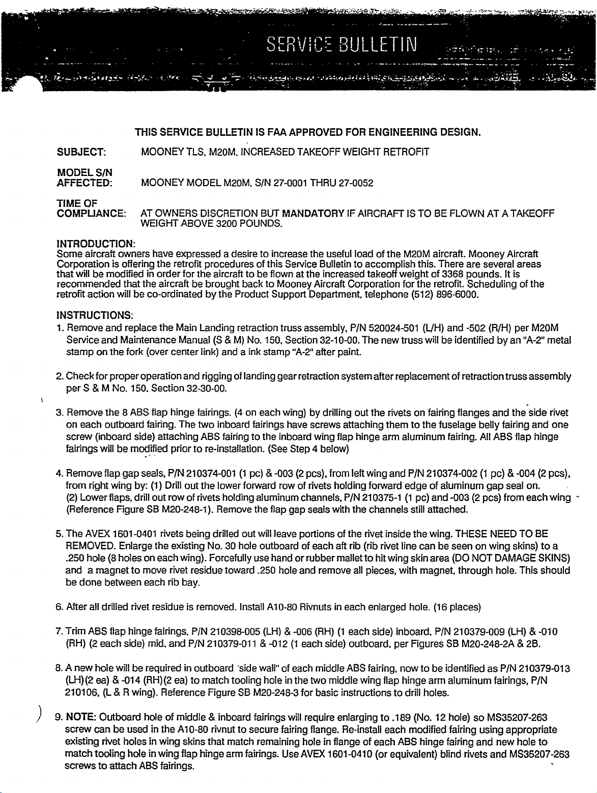
4.
Remove
from
(2)
(Reference
The
5.
REMOVED.
.250
and
be
After
6.
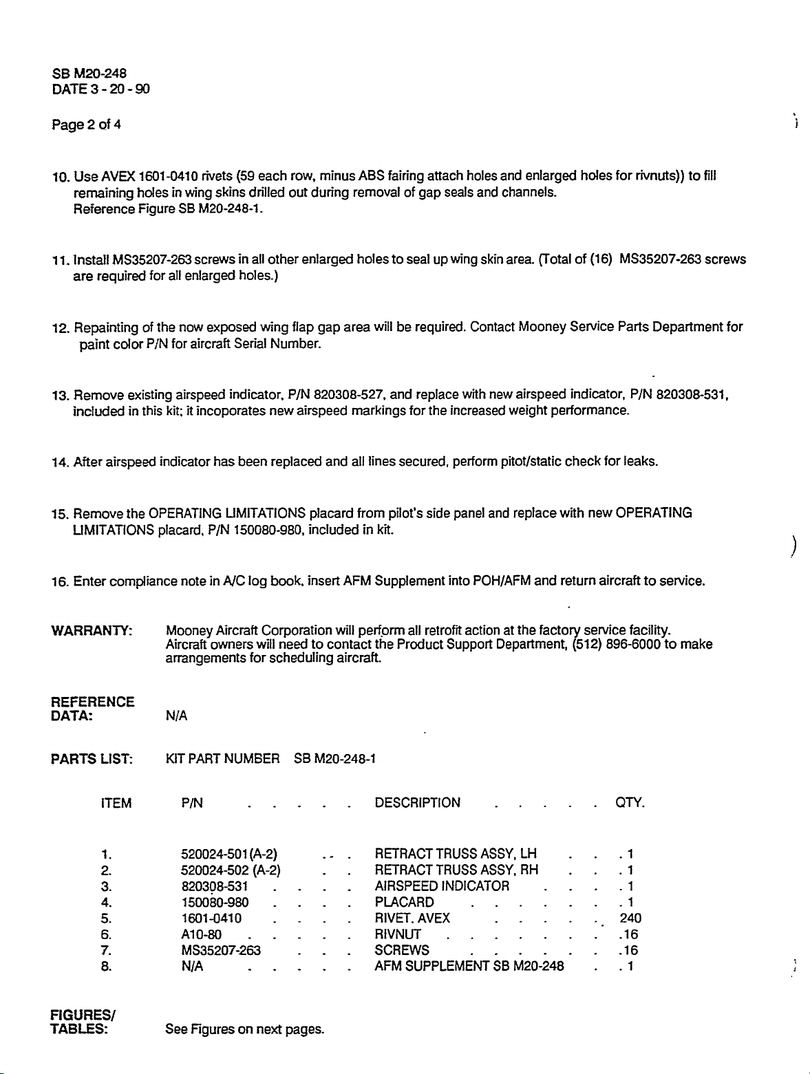
Trim
7.
(RH)
A
8.
new
(LH)(2
210106,
NOTE:
9.
screw
existing
match
screws
flap
wing
right
Lowerfiaps,
Figure
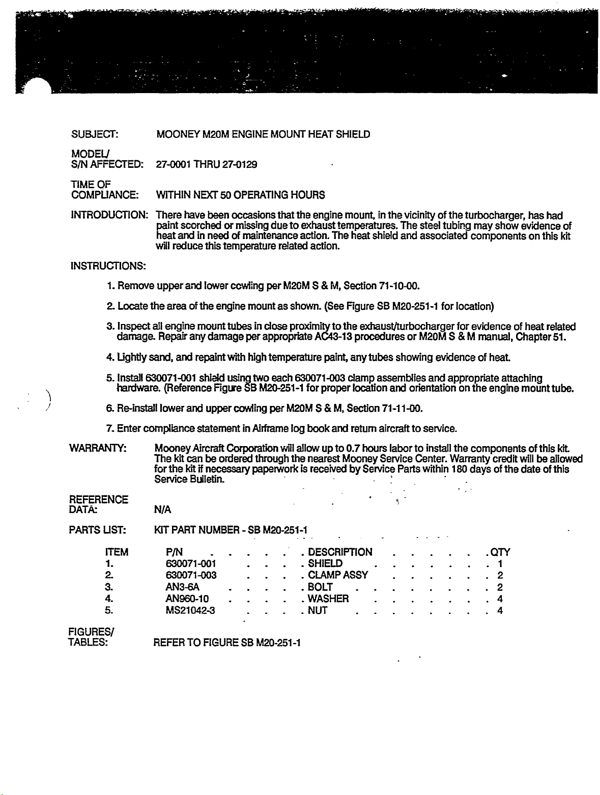
AVEX
1601-0401
hole
(8
a
magnet
done
between
all
drilled
ABS
flap
each
(2
will
hole
ea)
(L
Outboard
be
can
rivet
tooling
attach
to
seals,
gap
by:
drill
Enlarge
holes
on
to
move
each
rivet
hinge
side)
be
required
074
(RH)(2
R
wing).
holeofmiddle
usedinthe
holes
hole
ABS
P/N
Dn’ll
(1)
out
row
SE
M20-248-1).
rivets
the
existing
each
rivet
rib
residue
fairings.
and
mid,
Reference
in
wing
in
wing
fairings.
210374-001
out
of
being
wing).
residue
bay.
is
P/N
P/N
in
to
ea)
A10-80
skins
flap
the
rivets
drilled
No.
Forcefully
removed.
210398-005
210379-011
outboard
match
Figure
8
rivnut
that
hinge
lower
holding
Remove
30
toward
tooling
inboard
match
arm
(1
pc)
forward
the
out
hole
use
Install
’side
SE
M20-248-3
iairings
to
secure
fairings.
-003
row
aluminum
flap
gap
will
leave
outboard
hand
.250
hole
A10-80
(LH)
-012
wall"
of
in
hole
will
fairing
remaining
Use
pcs),
rivets
from
holding
(2
of
channels,
with
seals
portions
of
each
rubber
or
and
remove
R’Nnutsineach
-006
(RH)
each
the
for
middle
two
basic
side)
middle
(1
each
require
fiange.
in
hole
AVM
flange
1601-0410
left
210375-1
P/N
the
of
the
aft
rib
malletto
all
each
(1
outboard,
ABS
wing
instructions
enlarging
Re-install
of
wing
forward
channels
rivet
inside
rivet
(rib
hit
pieces,
enlarged
side)
fairing,
flap
to.189
each
each
(or
and
P/N
edge
(1
pc)
still
the
line
can
skin
wing
with
magnet,
hole.
inboard,
Figures
per
to
now
hinge
drill
holes.
to
(No.
modified
ABS
hinge
equivalent)
210374-002
of
aluminum
and
-003
attached.
THESE
wing.
be
seen
area
(DO
through
(16
places)
210379-009
P/N
SE
be
identified
aluminum
arm
12
hole)
fairing
fairing
blind
(1
pc)
gap
(2
pcs)
NEED
on
wing
DAMAGE
NOT
M20-248-2A
as
fairings,
M835207-263
so
using
and
and
rivets
-004
seal
on.
each
from
TO
skins)
This
hole.
(LH)
8r
28.
210379-013
P/N
appropriate
hole
new
MS35207-263
(2
pcs),
BE
to
SKINS)
should
-010
P/N
to
wing
a
M20-248
SE
DATE
Page
Use
10.
remaining
Reference
20
of
AVD:
90
4
holes
601-0410
1
holes
Figure
in
wing
SE
rivets
(59
skins
M20-248-1.
each
drilled
row,
out
minus
dun’ng
ABS
removal
fairing
of
gap
attach
seals
holes
and
and
enlarged
channels.
for
rivnuts))
fill
to
3
2
install
1
1.
are
required
12.
Repainting
paint
Remove
13.
included
After
14.
Remove
15.
UNIITAIIONS
Enter
16.
WARRANTY:
MS35207-263
for
of
PIN
color
existing
this
in
airspeed
OPERATING
the
compliance
screws
all
enlarged
the
now
exposed
aircraft
for
airspeed
it
kit;
incoporates
indicator
placard,
P/N
note
Mooney
Aircraft
arrangements
in
holes.)
Sen~al
indicator,
been
has
UMITATIONS
150080-980,
in
AVC
log
Aircraft
owners
all
other
flap
wing
Number.
P/N
new
replaced
book,
Corporation
will
need
for
scheduling
enlarged
gap
820308-527,
airspeed
and
placard
included
insert
to
contact
area
markings
all
AFM
will
aircraft.
holes
to
will
and
lines
from
pilot’s
kit.
in
Supplement
perforn
the
seal
be
required.
replace
for
secured,
side
retrofit
all
Product
up
the
Support
skin
wing
Contact
with
increased
perform
and
panel
into
POH/AFM
actionatthe
area.
CTotal
Mooney
new
airspeed
weight
pitot/static
replace
and
factory
Department,
of
(16)
Service
indicator,
performance.
for
check
with
new
aircraft
return
service
896-6000
(512)
MS35207-263
Parts
Department
P/N
820308-531,
leaks.
OPERATING
service.
to
facility.
to
screws
for
make
REFERENCE
DATA:
PARTS
LIST:
ITEM
i.
2.
3.
4.
5.
6.
7.
8.
FIGURES/
TABLES:
N/A
KITPARTNUMGER
P/N
520024-501
520024-502
820308-531
150080-980
1601-0410
Al
0-80
MS35207-263
NIA
See
Figures
on
(A-2)
(A-2)
next
SE
pages.
M20-248-1
DESCRIPTION
RETRACT
RETRACT
AIRSPEED
PLACARD
RIVET.
RIVNUT
AVEX
SCREWS
AFM
SUPPLEMENT
TRUSS
TRUSS
INDICATOR
ASSY,
ASSY,
SE
LH
RH
M20-248
QT/.
1
1
1
1
240
.16
.16
1
SE
M20-248
DATE3-20-90
Page
4
of
3
MS20600AD4
(61
REPLACE
DRILL
PLCS)
MIS
WITH
~210374
1601-0410
ROW
FLAP
OF
GAP
AVEX
RIVETS
SEALS
RIVETS
TRIM
DOTrrD
OUT.
EXISTING
DO
EXTEND
LINES
MS20600AD4
REPLACE
DRILL
210375
MS20470AD4
NOT
HOLDING
FIGURE
ABS
INDleArr
WITH
THIS
CHANNELS
(61
DRILL
FLAPS
CHANNELS
SE
FAIRINGS
UNTRIMMED
PLCS)
(67
16019410
ROW
OF
AVEX
RIVETS
RIVETS
PLCS)
THESE
AND
RIVETS
DRILL
OUT.
OUT
ON.
M20-248-1
DIMENSIONS
TO
SHOWN.
CONFIGURAT;IPH
OUT.
UPPER
ROW
OF
240014
RIVETS
FLAP
ASSY
-009
(SHOWN)
-olo
(092)
OFa\n\NC~>
3-CS
CONFKiURATION
NEW
~.Z5
210379
PIK
FIGURE
FAIRINGS
SE
FA\RI~G
M20-248-2A
OPP
’------I
\.2J
I
-011
-012
(SHOWN)
(OPP)
t
SE
DATE
Page
M20-248
3
4
of
90
20
4
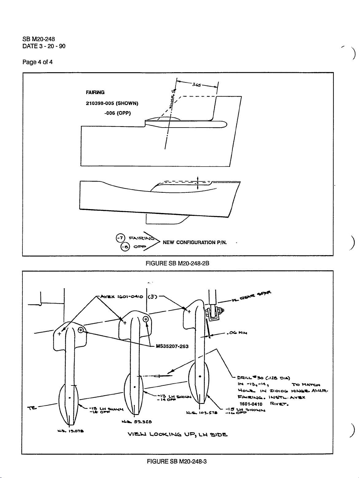
FAIRING
210398-005(SHOWN)
-006
(gpp)
0-~
o~c;
FIGURE
Slu2-I
NEW
CONFIGURATION
SE
M20-248-28
t
PIK
i/
-F
16019410
4P~C
LY
C.12~
Z1010CI
DI~
~o
hv~x
Rtvrr.
~VLX
160~-M\D
I I
I
(J)
V
klS35207-263
,*L~C
I
1´•11
’~b
L~
OCe
SE
Wow
U.L
UP)
M20-248-3
~De
-I~
--IcO~o
w
-14
I
I~-ts
~LI-
Izcn~
-\4´•
orr
*LI
COD~\huo
FIGURE
SUBJECT:
MODEU
AFFECTED:
SIN
TIME
OF
COMPLIANCE:
MOONC/
27-0001
WITHIN
M20M
THRU
NMT
ENGINE
27-0129
OPERATING
50
MOUNT
HOURS
HEAT
SHIELD
INTRODUCTION:
INSTRUCTIONS:
1.
Remove
2
Locate
3.
Inspect
damage.
4.
Lightly
5.
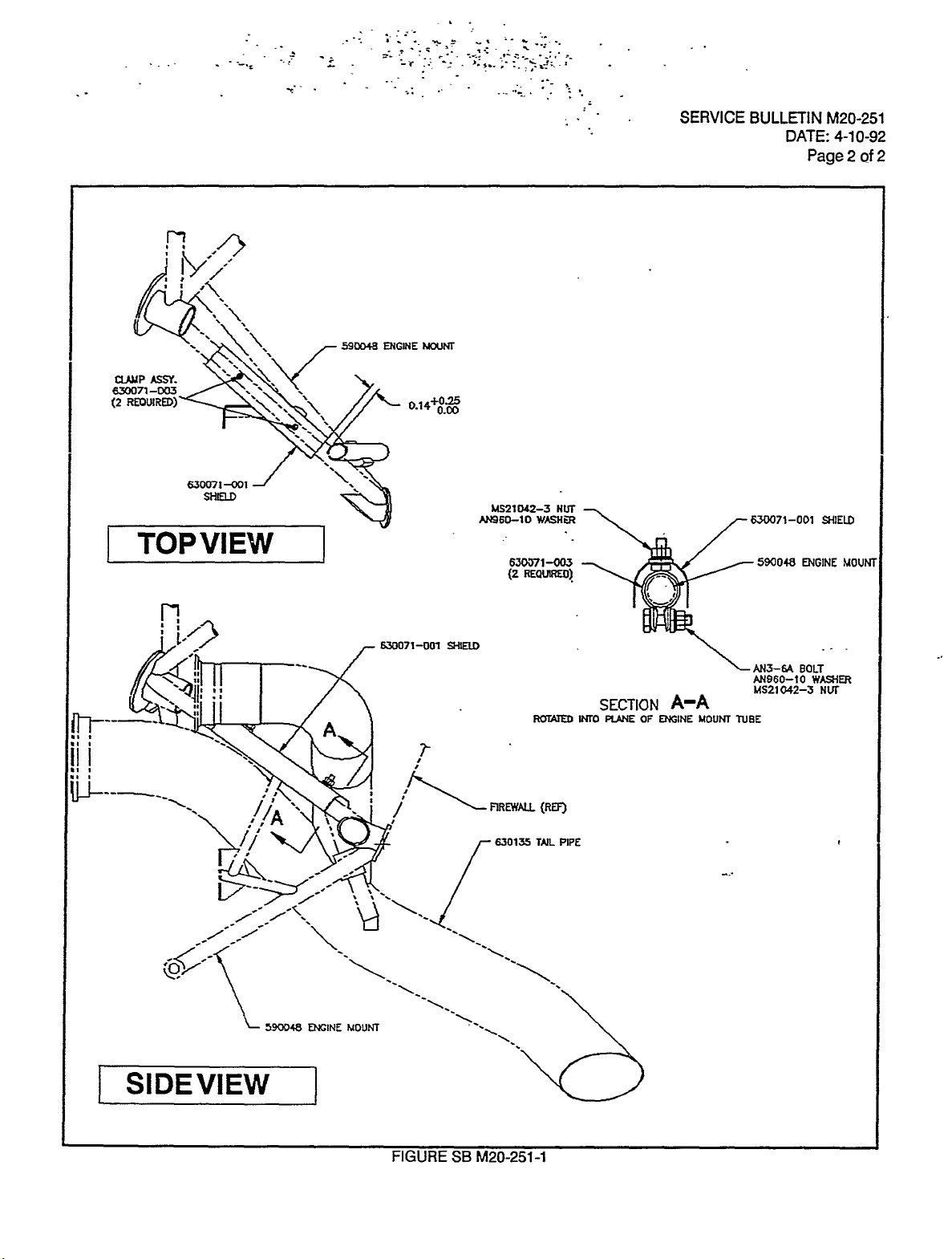
Install
hardware.
Re-install
6.
7.
Enter
WARRANP~
REFERENCE
DATA
There
have
scorched
paint
and
heat
will
reduce
upper
the
area
all
engine
Re~iir
and
sand,
630071-001
(Reference
lower
compliance
Mooney
kit
The
forthe
Service
N/A
in
and
of
mount
any
repaint
and
statement
Aircraft
can
kit
Bulletin
been
need
this
lower
the
engine
damage
shield
Figure
upper
be
ordered
if
necessary
occasions
or
missing
maintenance
of
temperature
ccwling
mount
in
tubes
appropriate
per
with
high
two
using
SE
MM251-1
cowling
in
Aimame
Corporation
through
paperwork
the
that
duetoexhaust
action.
related
M20M
per
shown.
as
dose
proximity
temperature
each
630071-003
for
M20M
per
book
log
will
allow
the
nearest
is
engine
The
action.
S
M,
(See
to
AC43-13
paint,
proper
S
and
up
received
mount,
in
temperatures.
heat
shidd
Section
SE
Figure
the
procedures
tubes
any
assemblies
damp
location
Section
M,
aircraft
retum
0.7
to
hours
Mooney
Service
by
the
vicinity
The
steel
and
associated
71-10-00.
M20-251-1
M20M
or
showing
and
orientation
71-11-00.
to
labortoinstall
Service
Center.
Parts
of
evidence
and
service.
within
the
turbocharger,
tubing
may
components
for
location)
for
evidence
S
M
appropriate
the
on
the
components
Warranty
180
days
show
manual,
of
heat.
attaching
engine
credit
of
evidence
of
Chapter
mount
will
dateofthis
the
has
on
heat
of
this
this
be
had
of
kit
related
51.
tube.
kit
allowed
PARTS
FIGURESI
TABLES:
USTr
ITEM
1.
2
3.
4.
5.
KIT
PART
P/N,,....
630071-001
630071~03
AN3-6A
AN960-10
MS21
REFER
NUMBER
042-3
TO
FlGURE
-SB
SE
M20-251-1
M20-251-1
DESCRIPTION
SHIELD
CLAMP
BOLT
.WASHER
NUT
ASSY
.QTY
1
2
2
4
4
I;
-T
T
~-ci.
CUUP
ASSY.
530071-003
(2
REOWRED)~
TOP
n
i´•/´•l~
SHIELD
VIEW
590048
~t
ENGINE
NOUNT
0.00
MM1M2-3
AN950-10
WASHER
630371-003
~2
REaVatEO)
HUI
Ifi~
SERVICE
BULLETIN
/-530071-001
590048
DATE:
Page
PICINE
M20-251
4-10-92
2
SHIEU)
.UOUNI
2
of
ii
i
ii~----_,
SIDEVIEW
-~3
~Jm
V
sylml-atn
I
~iRREWW.
4lmo
AN3-6A
SECTION
550
ROTATED
1-
(RD)
630135
WL
PUIEIE
PIPE
A-A
OF
~GINE
LIDUNI
TUBE
AN860-10
MS21042-3
BOLT
WASHER
NLIF
-i
d
´•ti
FIGURE
SE
M20-251-1
SUBJECT:
MODEU
AFFECTED:
S/N
TIME
OF
COMPLIANCE:
.tions.
tions
of
cal
some
stop
This
have
has
found
ofthe
has
components
INSTRU~TIONS:
i.
Raise
Remove
2
not
caused
that
components
been
developed
of
SE
aircraft
M20M
LANDING
M20M
27-0137,
WlTHlN
Some
aircraft
difficulty
some
wilt
Kit
allow
on
composite
S/N
27-0107
27-0142,
NMT
within
of
the
is
recommended.
to
be
field
jacks
per
belly
GEAR
27-0144,
FLIGHT
25
the
with
the
mechanism
installed
personnel
Service
skins
RIGG)NG
THRU
HOURS
above
27-0147
27-0150
S/N
INSPECTION
OR
block
retraction/extension
components
To
eliminate
in
the
wheelwells.
retrofit
to
and
Maintenance
M
S
per
manual,
AND
HAD
NDCT
have
27-0115,
INSTRUCTIONS
SCHEDULED
experienced
(S/N’s
HAVE
AT
cycle
have
gone
the
possibilityofexceeding
The
instructions
(S
Section
aircraft.
h;l)
53-30-00.
applicable
MODIFICATION.
27-0123,
landing
in
of
the
any
beyond
manual,
normal
of
Section
27-0127,
OF
SE
ACCOMPLISHED).
MAINTENANCE.
inner-door
gear
cases.
Maintenance
tolerance.
tolerances,
Service
this
71-10-00.
27~131,
Replacement
mechani-
a
Bulletin
malfunc-
inspec-
and
and
rods
spections
Instructions
When
landing
mechanical
attaching
550075501
ces,
which
hole
attached
Perform
3.
4.
On
(5),
5.
Re-n’g
stop
Aircraft
6.
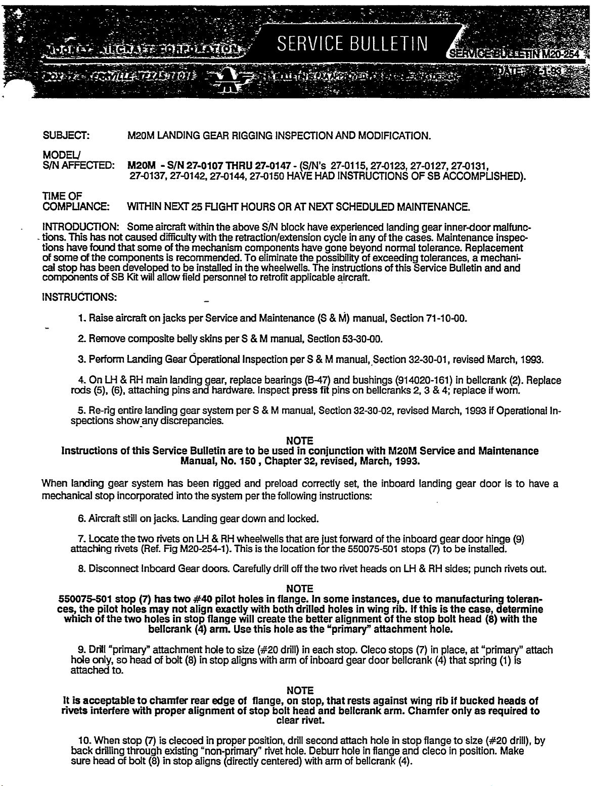
Locate
7.
Disconnect
8.
the
ofthe
Drill
9.
only,
LH
(6),
entire
showany
of
gear
incorporated
still
the
rivets
stop
holes
pilot
two
"primary"
so
to.
Landing
RH
Gear
main
attaching
landing
discrepancies.
this
Service
system
on
jacks.
rivets
two
(Ref.
Fig
Inboard
has
(7)
may
holes
bellcrank
attachment
headofbolt
dperational
landing
and
pins
gear
Bulletin
Manual,
has
been
into
the
Landing
on
M20-254-1).
Gear
two
#40
not
align
in
stop
(4)
(8)
gear,
hardware.
system
system
LH
doors.
fiange
arm.
hole
in
stop
replace
are
No.
n’gged
gear
RH
Carefully
pilot
exactly
to
aligns
Inspection
Inspect
S
3
per
to
be
150
and
the
per
down
whedwells
This
is
holes
with
viill
create
this
Use
size
(i5~20
with
per
bearings
press
M
manual,
NOTE
used
Chapter
preload
following
and
locked.
that
the
location
drill
off
NOTE
in
flange.
both
the
hole
dn’ll)
arm
S
(B-47)
fit
Section
in
conjunction
revised,
32,
correctly
instructions:
are
just
for
the
two
In
some
drilled
better
the
as
in
each
of
inboard
M
manual,~Section
and
bushings
bellcranks
on
pins
32-30-02,
with
March,
the
inboard
of
heads
forward
the
rivet
set,
550075-501
instances,
in
holes
alignment
’primary"
stop.
gear
wing
of
attachment
Cleco
door
32-30-01,
(914020-161)
3
2,
revised
M20M
1993.
March,
Service
landing
the
inboard
stops
LH
on
doe
rib.Ifthisisthe
the
stops
bellcrank
gear
(7)
RH
to
manofacturing
bolt
stop
hole,
in
(7)
(4)
revised
in
4;
replace
and
gear
be
to
sides;
head
place,
that
bellcrank
1993
Maintenance
door
door
installed.
punch
case,
at
"primary"
spring
March,
(2).
if
worn.
if
Operational
istohave
(9)
hinge
rivets
toleran-
determine
with
(8)
is
(1)
1993.
Replace
In-
a
out.
the
attach
It
rivets
back
sure
is
10.
acceptable
interfere
When
drilling
head
of
to
with
stop
through
bolt
chamfer
proper
is
(7)
(8)
alignment
decoed
e>dsting
in
stop
rear
edge
in
proper
"non-primary"
aligns
(directly
of
Range,
of
stop
position,
NOTE
on
bolt
head
clearrivet.
drill
rivet
hole.
centered)
stop,
second
Deburr
with
and
that
arm
rests
bellcrank
attach
hole
of
bellcrank
against
hole
in
Range
arm.
in
wing
Chamfer
stop
and
(4).
rib
Range
cieco
if
bucked
only
size
to
in
position.
as
heads
required
(#20
Make
drill),
of
to
by
SERVICE
BULLETIN
DATE:
M20-254
Page
4-1-93
2of4
lNSTRUCTIONS:
11.
Rivet
rivets
12
Leave
in.
way
Two
mechanics
Retract
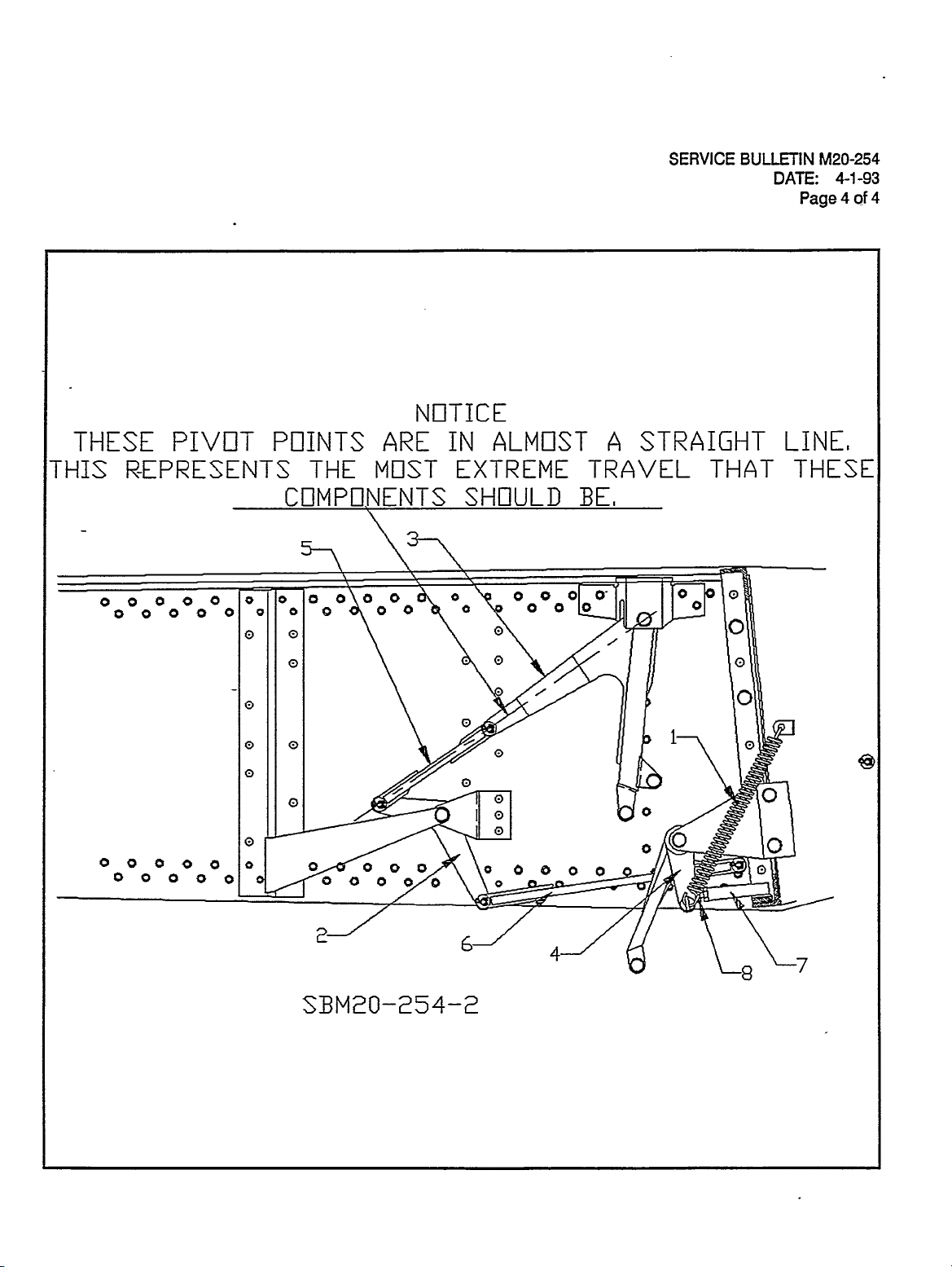
13.
door
gear
bellcrank
(2),
(5)
14.
Adjust
rods
(5)gr(6)
head
(8)
15.
Repeat
whedwdl.
16.
Cycle
after
cycles
done
as
M,
17~
Ccmplete
included
has
(3)
(6)
is
(con’t)
stops
in
spring
landing
traveled
center
should
stop
become
in
correct
installation
landing
for
any
in
Step
lag
P/N
(1)
550075-501,
kit.
Re-attach
attached
t/),
this
(personnel)
other
gear
as
line
be
now
bolt
head
loose
position.
of
through
gear
interference,
No.
3.
boole
entry
Inboard
clevis
to
be
safety
it
-(5)
loaded
a
OUT
load
required
the
willgo
will
until
may
inside
using
far
as
of
rod
in
(8)
(no
Tighten
stop
(7)
(Steps
five
complete
bindingorimproper
and
retum
each
of
aircraft
wheelwell
Gear
inboard
for
in
by-pass
during
in
be
a
condition
it
rests
feltoneither
nut
7
thru
aircraft
on
jam
at
the
doors
door
NOTE
the
next
operating
switch
(See
its
retraction
straight
and
feel
bellcrank
on
rod).
bolt
(8)
and
11)
line
location
before
bellcrank
several
the
landing
S
cycle.
(Reference
very
(4)
Bellcrank
against
adjustment
retraction/extension
operation.
to
service.
cycling
(4).
steps.
Section
M,
In
tight.
arm.
(2)
tube
cycles;
Reference
descn’bed
landing
Bolt
head
One
switch.
gear
32-30-01,
this
position,
Figure
Continue
will
on
M20-254-2).
also
become
stop
procedures
inspect
Operational
gear
(8)
under
to
(7).
(Steps
in
steps
for
should
steps
the
adjust
all
components
8
9
following
be
screwed
the
aircraft
5, 6,
pivot
points
Components
bolt
head
loose
when
12
thru
Inspection
above
steps.
7)
14)
and
until
of
OUT
bolt
in
during
in
S
using
all
the
inboard
until
other
the
and
WARRANP~
REFERENCE
DATA:
PARTS
UST:
lTEM
1
2
3
4
5
6
7
8
9
10.
11.
be
FlGUREl
TABLES:
At
some
available
will
Aircraft
be
forms
Mooney
Kit
warranty
N/A
KIT
PART
.P/N
~550075601
.550082-503
.550082-505
.91
4020-1
.8-47
.MS20392-2C7
.MS20392-2C9
.MS20392-2C17
.AN381-2-6
.AN470AD5-13
M20M
later
date
the
field
to
SEE
NDCT
ordered
within
NUMBER
61
S
M
the
complete
and
PAGES
Corporation
through
180
days
SBM20-254-1
S
be
not
may
FOR
FlGURES
will
allow
Mooney
of
M
will
included
hours
3.0
Service
the
issue
DESCRIPTION
STOP
ASSY.
LOWER
ROD,
UPPER
ROD,
BUSHING
BEARING
CLNIS
PIN,
CLNIS
PIN,
CLEVIS
PIN,
COTTER
PIN,
RIVET
Chapter
be
revised
in
this
SBM20-254-1
labor
Centers
dateofthis
(PRESS
(PRESS
kevised
32,
and
Chapter
Service
with
will
Bulletin.
and
to
comply
credit
Service
FIT:BELLCRANK
FIT-BELLCRANK
3-93’
as
32,
Bulletin
AND
kit.
SBM20-254-2
this
be
revised
issued
Service
upon
4)
i&
in
March,
3)
Bulletin.
receipt
QTY
.2
.2
.2
.2
.2
.2
.4
.2
.8
.4
.1
1993,
Parts
of
will

SERVICE
BULLETIN
DATE:
M20-254
Page
4-1-93
3of4
2
--~21
I,I
al
61
spi~P
dp"‘’
3~
5~
II
II
p’’
a
a
SBM20-25
I!
11
O
a
o~
I
~\o
a
o
a,
\~4
0\
L.9
4´•-1
NI7I1CE
SERVICE
BUU-FTIN
DATE:
M20-254
Page
4-1-93
4
of
4
THESE
THIS
PIVDT
R-EPRESENTS
P[71NTS
THE
CDMP
ARE
M[7ST
ONENTS
ALMOST
IN
EXIREME
SHOULD
i
A
TRAVEL
BE,
STRAIGHT
THAT
LINEI
THESE
o
SBM20-254-2
SERVICE
ISSUEDATE:
BUU~ETIN
Novemberl’l,
M20-255A
1993
I
SUB3ECT:
MODELSISIN
AFFECTED:
OF
TlME
COMPLIANCE:
INTAODUCTION:
INSTRUCTIONS:
PART
(S/N
it
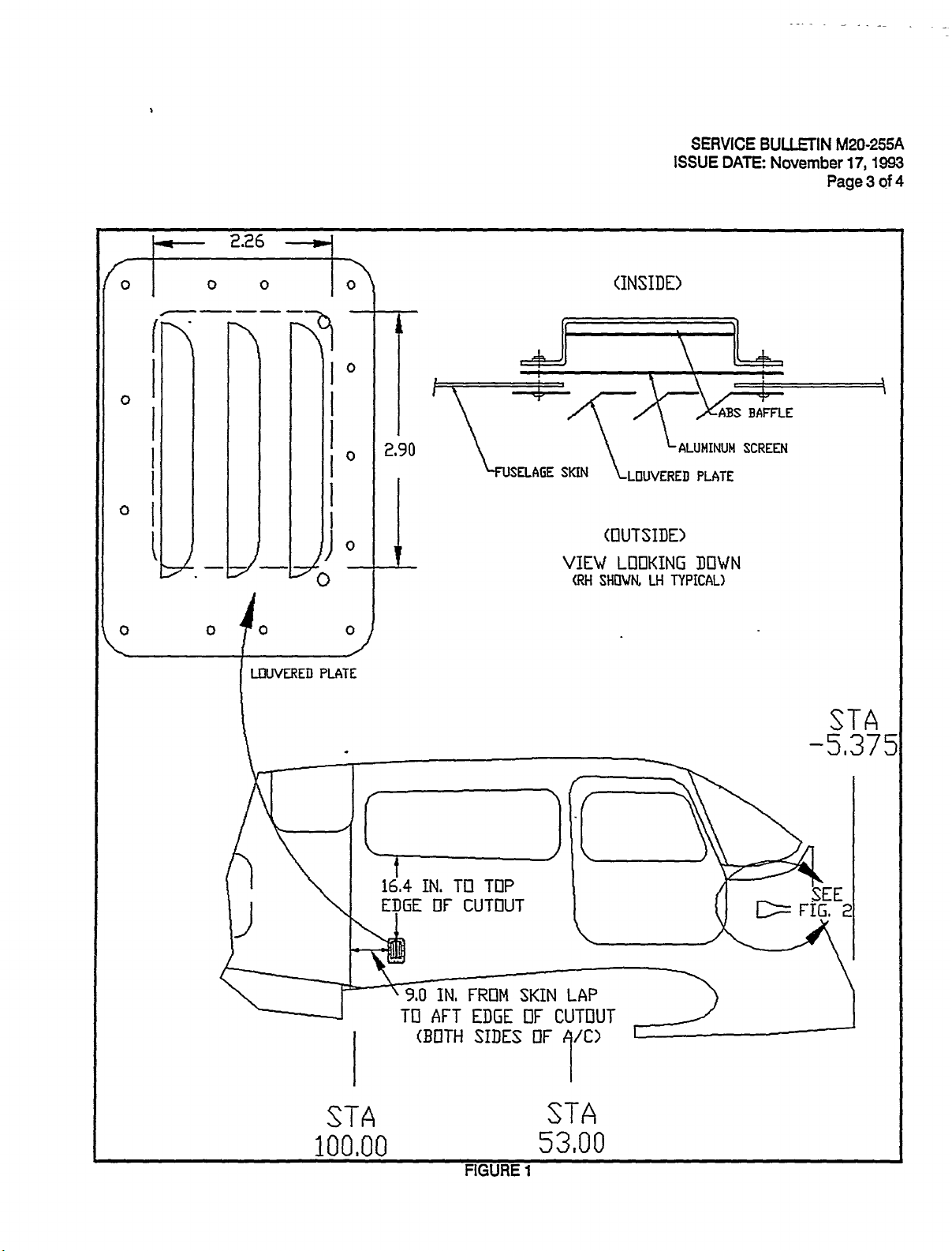
1.
sides.
restrained
to
accomplish
Caution
Locate
Z
skin
lap,
of
each
with
vertical
Deburrcut-out
3.
Cleco
4.
in
baffle
should
sembly.
After
5.
screen
awl.
Repeat
Place
6.
M20-255-1.The
ches
edge
holesinlowered
hole..
install
7.
(insideoffuselage
screen
for
UH
Clean
3.
Paint
9.
Enter
10.
RI
Il.
Mooney
PART
PART
PART
Within
In
needs
ADDCABIN
27-0002
is
recommended,
The
long
UP
to
the
be
area
forward,
cut-out
skin
640296-001
lowered
and
Ident~y
NOTE:
drilling
between
for
640130-000
R/H
distance
lowered
RM
between
side.
area
up
rivets,
compliance
and
out
1:
2:
3:
next
order
to
to
thru
ABS
panels,
provide
retrofit
observed
drill
of
fuselage
9.0
should
lap.
lowered
Be
i4~30
baffle
UH
side
RIH
location
should
plates
skin)
ABS
and
attaching
return
M20M,
Retrofit,
M20M
M20M
M20M
25
Right
provide
be
accomplished
D(HAUSTVENTS
27-0167,
but
not
forward
access
S/N
SM
SRN
hours
a
excluding
essential,
to
during
through
inches
be
Recommended
ABS
plate
sure
matching
skintobe
and
inches
29
baffle
are
plates
that
and
any
dawn
matched.
as
louvers
holes
UH
sub-assembly.
lowered
the
of
lowered
be
maintained
(13
places
plate
(outside
with
install
note
Avex
and
ABS
lowered
in
log
inside
book
baffle
pre-addressed,
cabin
27-0002
27-0053
27-0002
at
or
continual
for
to
the
of
the
inside
out
cut
electrical
cut
16.4
high
radiusonall
lowered
to
a
Drill
RIH
and
will
in
baffle
lowered
in
plate
plate
far
each
of
fuselage
1691-0410-05
surface
interior
plates,
and
stamped
exhaust
next
purge
serial
THRU
THRU
THRU
vents
27-0137
27-0167
27-0052
scheduled
of
the
numbers
on
cabin
listed
(F1G.SBM20-255-1)
S/N
27-0094)
aft
remove
baggage
skin.
hole
of
wiring,
out
by
inches
and
2.26
plate
all
UH
have
and
plate;
position,
does
for
all
plate).
of
panels,
match
to
return
compliance
pilot
during
fasteners.
rivetsand
fuselage
interior
campartment
These
long
and
drilling
ABS
measuring
from
lower
wide.
inches
for
holes
of
UH
this
comers
openings
lowered
punch
matching
RIH
over
have
not
Reference
R/H
skin),
skinasshown
ii
remaved.
exterior
aircrafttoservice.
fuselage
(D(CEPT
(EXCEPT
maintenance
air,
compliance
above.
baggage
panels,
ABS
rivet
of
from
or
the
panels
edge
Keep
cut-out
side
sub-assembly
#30
out
to
procedure.
toward
sandwich
plate,
cut-out
be
to
#30
Pig.
aluminum
paint
card.
exact,
SE
color.
Drill
AN960-6
sideslcabin
S/N
S/N
panels
holes
tubular
baggage
of
ah
vertical
is
.125
holes.
the
aft
holes
hole,
holes
M20-255-1.
screen
washers.
ventilation
27-0094)
27-0094)
action.
of
this
compartment
will
need
be
may
window
inches.
endofthe
through
however,
in
in
Fig.
removed,
in
fuselage
structure.
campartment/cabin
skin
sides
to
verify
Repeat
a
640247-003,
screen
in
accordance
a
fuselage
Repeat
and
640246-002
Sandwich
SE
M20-255-1.
Service
ABS
be
to
clrt-out.
of
cut-out
(Fig.
for
aircraft.
minimum
skin
system
Bulletin
panels,
pulled
if
skin
parallel
SE
M20-255-1)
that
all
side
R/H
aluminum
mesh
with
to
match
for
UH
aluminun
both
UP
desired,
soas
area,
The
size
pilot
sub-as-
with
Fig.
of
.31
#30
cut~ut
ABS
Repeat
modifiction.
and
not
to
vertical
holes
an
SE
inr
baffle
I
I
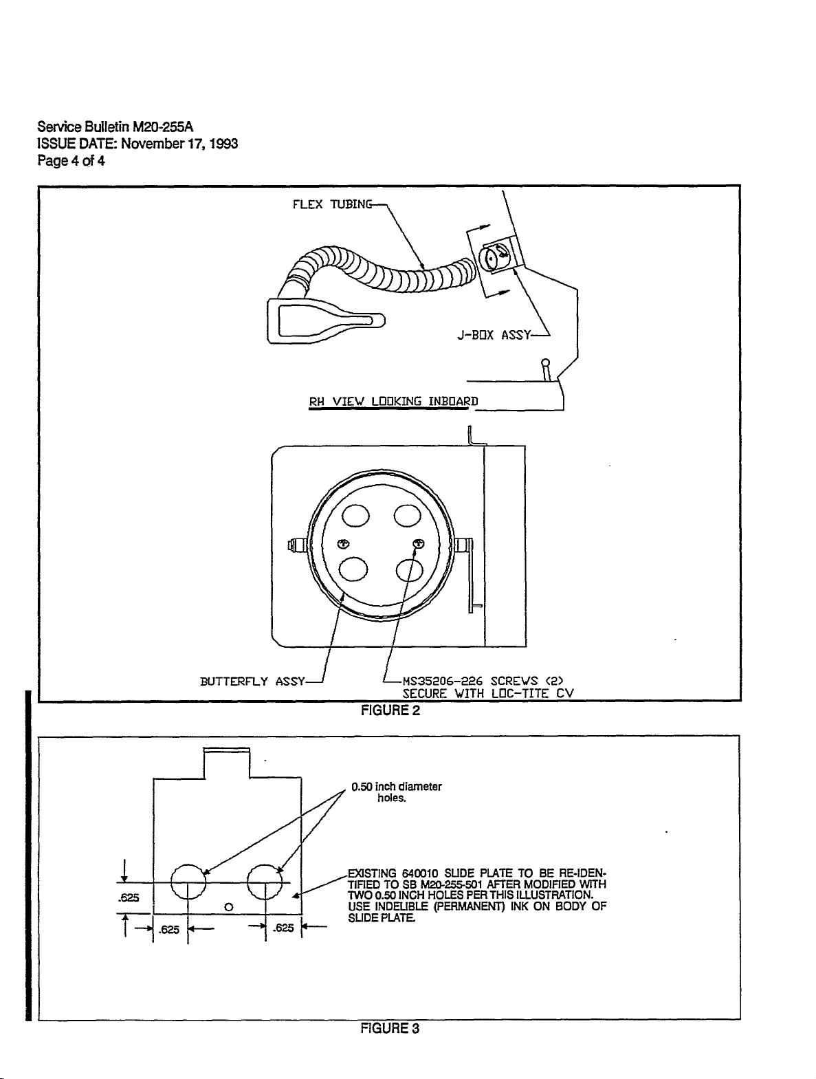
PART
1,
2.
replace
255-2
3.
4.
5.
2:
REPLACE
27-0053
(S/N
Locate
Access
cabin
J-Box
existing
Re-instaI(ffextubingto
Enter
compliance
Fill
out
and
THRU
ventilation
assembly
640326-505
note
retum
pre-addressed,
27-0167
J-Box
by
butterfly
J-Boxwith
in
ASSEMBLY
excluding
in
loosening
book
log
SIN
forward,
QS100-M40S
assembly
QS100-M40S
and
retum
stamped
1N
CABrN
27-0094)
RH
cabin
with
new
clamp.
aircraft
compliance
VENLlVITION
immediately
J-Box
at
clamp
640326-511
to
service.
card.
J-BOX
behind
and
butterfly
(FIG.
firewall.
flex
tubing
assembly,
SE
M20-255-2)
connection;
SE
Fig.
I
M20-
SERVICE
ISSUE
2
Page
BULLETIN
DATE:
of
4
November
M20-255A
17,
1993
PART
3:
(S/N
1.
2.
connection.
sembly/cable
3.
SE
P/N
4.
and
5.
6.
installation
7.
8.
9.
Applicable
WARRANP~
Mooney
S/N’s
paper
Aircraft
27-0002
work
(September
MODIRCATION
27-0002
Locate
Access
Modify
M20-255-3.
on
Re-install
hardware.
Position
Verify
Re-install
Enter
Fill
kits
cabin
J-Box
Use
640010-000
body
slide
of
compliance
outand
should
Corporation
TH
RU
is
received
29,
1993)
OF
SUDE
THRU
27-0052)
stops
Slide
slide
of
modified
slide
plate
flex
ventilation
slide
needle
from
Plate
plate.
prate
operation
tubing.
plate
nose
slide
slide
must
slide
MS16562-4
so
J-Box
assembly
pliers
plate.
plate
now
plate
is
flextubingtoJ-Boxwith
in
return
be
27-0137
from
of
this
note
pre-addressed,
ordered
will
and
Service
Service
from
allow
1.0
log
4.0
hours
Center
Bulletin.
PLATE
in
forward,
to
remove
Remove
dnlling
by
be
into
J-Box
roll
smooth
QS100-M40S
book
stamped
Mooney
hours
labor
by
Normal
CABIN
ON
loosening
by
e~dsting
two
re-identified
assembly.
can
pin
and
and
retum
Service
labor
on
A/C
Mooney
warranty
VENTILATION
RH
cabin
QS100-M40S
MS16562-4
640010-000
0.50
as
be
inserted
complete
clamp.
aircraft
compliance
Centers.
to
incorporate
S/N’s
Service
immediately
roll
pin
inch
diameter
SE
P/N
Attach
travel
M20-255-501;
cable
into
can
to
service.
card.
applicable
27-01
38
Parts
Department
procedures
J-BOX
clamp
from
slide
hole
be
THRU
on
(FIG.
behind
on
slide
platetrom
in
holes,
assembly
through
obtained
portions
27-0167
and
parts
SE
firewall,
J-Box
plate.
locations
use
with
outlet
in
if
within
kit
M20-2553)
outlet
air
Remove
J-Box.
showninFIG.
as
indelible
existing
air
flex
both
directions,
of
Service
this
compliance
180
days
components
cable
ink
cable
of
flex
to
tube
card
tubing
as-
mark
stops
opening.
prior
Bulletin
and
the
will
to
on
warranty
on’ginal
be
followed.
AIC
date
REFERENCE
DATA:
PARTS
UST:
2
3.
4
5.
6.
7.
8.
NOTE
1.
2
3.
FIGLERES/
TABLES:
Item
1.
Matching
NIA
PART
..Part
.640130-000,..
,640247-003
1691-0410-05
.AN960-6
-64029~-001
.640296-002
Paint
,Compliance
paint
PART
6$0326-511
.MS35206-226
Compliance
See
Figures
1-
Kit
Number
will
be
2
Kit
Part
Card
shipped
Part
Card
SE
M20-255-1,
Number
Number-
with
-SB
kit.
SE
SE
M20-255-1
Descn’ption
Plate,
Screen,
Rivet
Washer
Baffle,
Baffle,
To
To
Provide
M20-255-2
Butterfly
Screw
To
M20-255-2
match
be
aircraft
be
(S/N
Louvered
Aluminum,
(AVD()
ABS,
ABS,
AIC
retumed
S/N
(S/N
assembly
retumed
and
SE
27-0002
(Painted)
LH
RH
color
to
when
27-0053
to
M20-255-3
MRU
(16
mesh)
Service
orden’ng
MRU
Service
27-0137
Parts
27-0167,
Paris
on
following
above
U(CEPT
kit
part
MCEPT
pages.
27-0094)
Quantity
.2
.2
26
26
.1
.1
.1
.1
number.
27-0094)
.1
.2
.1
2.26
SERVICE
ISSUE
DATE:
BULLETIN
November
M20-255A
17,
Page
3
1993
of
4
o
o
lo\
(INSIDE)
~ci
10
BAFFLE
ALUMINUM
10
2,90SKIN
1
~I
I
I
I
III´•
O
O
O
-T~O
LOUVERED
O
PLATE
VIEW
(RH
(CIUTSIDE)
LOOKING
SHOWU
LH
I)OWN
TYPICAL)
SCREEN
PLATE
STA
-5,37
c-1
16.4
IN.
TO
TOP
OF
ET~GE
CUTOUT
\I
j
9,0
IN,
STA
100,00
TO
AFT
(BOTH
FRON
EDGE
SIDES
FIGURE
SKIN
OF
OF
STA
53,00
1
LAP
CUTOUT
SEE
Senrice
ISSUE
Page
Bulletin
DATE:
4of4
M20-255A
November
17,
1993
FLEX
BUTTERFLY
ASSY--,
RH
VIEW
O
O
LDtlKING
LMS35206-226
FIGURE
O
SECURE
2
J-BI7X
INBOARD
WITH
ASS
SCREVS
LOC-TITE
<2>
CV
.625
?-1
.625
inch
0.50
TIRED
TWO
O
USE
SLIDE
diameter
holes.
640010
TOSEM20´•255-501
INCH
0.50
INDEUBLE
PLATE.
SUDE
HOLES
(PERMANENT)
PER
PLATE
AFTER
THIS
RE-IDEN-
BE
TO
MODIRED
ILLUSTRATION.
ON
BODY
INK
WITH
OF
´•u~-
FIGURE
3
THIS
SERVICE
BULLETIN
FAA
APPROVED
IS
FOR
ENGINEERING
DESIGN
SUBJECT:
MODELSISIN
AFFECTED:
TIME
OF
COMPLIANCE:
INTFZODUCTION:
i,
Bendix-King
cuit
progress
malfunctions:
or
2
The
necessary
Seivice
BENDU(-MNG
76A
KT
ALL
M20E,
HADAKT
M20B,
F~EFERTOBENDIX-KING
of
(IC)
to,
The
The
2)
MODELS
Service
the
an
unit
unit
ATC
M20F,
76A
M20D,
KT76A,
electronic
may
may
t~ansponder
subject
Bendix-KingSEprovides
for
Centers.
the
retrofit
SERVICE
TRANSPONDER
MOONC(AIRCRAFT
OF
M20J,
M20K,
TRANSPONDER
M20G,
Bulletin
OR
No.
P/N
066-1062-00/10!02,
breakdown
incorrectly
transmit
unit.
procedures
BULLETIN
M22)
KT76A-7
interpret
code
a
M20L,
KT
SE
within
other
the
to
No.
MANUFACTURED
M20M,
RETROFI~ED
(APPUES
76A-7,
provides
Sn\l’s
IC
the
the
output
than
compliance,
be
accomplished
KT
SE
AND
TO
DATED
information
that
what
76A-7,
M20FP
SINCE
ALL
JULY/96
from
causes
of
the
is
set
retrofit,
ISSUEDATE:
JULY/96
AND
i
S/N’s)
that
93,000
either
encoding
land
warranty,
by
appropriately
SERVICE
SINCE
ANY
975
(INCLUDES
later
(or
indicates
to
109,000,
or
attimeter.
shown)
BULLETIN
later
(or
1975
MODEL
(INCLUDES
revision(s)
the
may
bothofthe
the
on
and
parts
rated
iDecember,
revision(s)),
THAT
MAY
M20,
integrated
possess,
following
faceofthe
list
information
Bendix-King
M20-261
1996
M20C,
HAVE
M20A,
cir-
or
INSTRUCTIONS:
WARRANPI:
REFERENCE
DATA:
PARTS
F1GURES/
TABLES:
LIST:
REFER
I~EFERTO
~EFER
F~EFER
FIEFERTO
TO
BENDU(-KING
BENDIX-KING
TO
BENDD(-KING
TO
BENDU(-KING
BENDIX-MNG
SE
SE
SE
SE
SE
Kr76A-7,
KT
76A-7,
KT
76A-7,
KT
76A-7,
KT
76A-7,
DATED
DATED
DATED
DATED
DATED
JULY/96
JULY/96
JULY/46
JULY/96
JULY/96
(or
(or
(or
(or
(or
later
later
later
later
later
revision(s)
revision(s)
revision(s)
revision(s)
revision(s)
THIS
SERVICE
BULLETIN
ENGINEERING
FAA
APPROVED
IS
FOR
DESIGN
SUBJECT:
MODELS/S/N
AFFECTED:
TEX~RON
SUBSEQUENT
ME
1)
No.
2)
BEEN
3)
ANY
IF
LYCOMING
TIONS
SERVICE
M20A,
THRU
ENGINES
PISTON
17
SEPTEMBER,
M20J
URED
PRODUCTION.
M20M
IF
LYCOMING
FOLLOWING
IF
LYCOMING
5278
CYUNDERASSEMBUES
IF
REPIJ\CED
if
PISTON
MUST
M20B,
243380
SIN’s
BETWEEN
SUBSEQUENT
(OR
OF
2)
1),
SERVICE
BE
BULLETIN.
M20C,
CYUNDERASSEMBLIES
OR
FINS
ONLY,
24-3381
SIN
27-0001
INDERASSEMBLIES
SUPPLIED
M20M
SIN
LYCOMING
BY
27-0212
SERVICE
REVISIONS),
AIRCRAFT
ENGINE
SINCE
PINS
ONLY,
ABOVE
OR
3)
BULLETIN
ACCOMPLISHED
M20D,
IF
RETROFITTED
SUPPLIED
1996.
MRU
15
DECEMBER,
THRU
v\nTH
NEW,
(PISTONS
MRU
BULLETIN
RECALL
SHOULD
S/N’s
REVISION
OM-IICH
15
DECEMBER,
HAVE
CONDITIONS
M20E,
BY
24-3389,
27-0210
OVERHAULED
8
BETVMW
27-0214,
OF
LISTED
BEEN
No.
5278
ACCORDANCE
IN
M20F,
WITH
LYCOMING
24-3391
1995
WITH
PISTON
15
27-0217
No.
PISTON
INSPECTED
BE
SUBJECT
ON
ARE
INCLUDE
1995
REPLACED
ARE
(OR
M20G
NEW,
(PISTONS
AIRCRAFT
THRU
17
-AF1B
OR
PINS
DECEMBER
SERVICE
ISSUEDATE:
DATED
5278,
PIN,
LW14077
P/N
DETERMINE
TO
LYCOMING
INSTALLED.
PISTONS
SINCE
FOUND,
15
COMPLIANCE
SUBSEQUENT
ALL
WITH
SIN’s
AL,
OVERHAULED
PISTON
8
BET~
15
WITH
SEPTEMBER,
ENGINE
REMANUFACTURED
IN
RETROFIT
CYLINDERS)
1995
THRU
BULLETIN
8
OCTOBER,
SERVICE
AND
PISTON
DECEMBER,
REVISIONS)
PARAMETERS
M20J
8
REMANUFACTURED
OR
PINS
IN
ENGINES
INSTALLED
1996
KIT
PISTON
OR
17
SEPTEMBER,
CYLINDERS)
DECEMBER
10January,
1996,
BULLETIN,
PINS)
1995
WITH
INSTRUC-
S/N’s
1995
MANUFACT-
INSTALLED
ENGINES
PINS
M20-262
1997
(OR
HAVE
OF
THE
24-0001
OR
THRU
DURING
OR
ONLY,
1996.
OR
Cn-
OF
TIME
COMPLIANCE
INTF~ODUCTION:
INSTRUCTIONS:
VWRRANTY:
REFERENCE
DATA:
PARTS
FIGURESI
TABLES:
LIST:
NOTE:
Aircraft
determine
Serial
Lycoming
SEETDCTRON
LATER
(OR
SEETMTRON
LATER
(OR
SEETDCTRON
LATER
(OR
SEETDCTRON
LATER
(OR
SEE
TEXTRON
LATER
(OR
TDCTRON
SEE
LATER
(OR
SEE
TECTRON
LATER
(OR
Number
final
applicability,
Service
Bulletin
LYCOMING
REVISION)
LYCOMING
REVISION)
LYCOMING
REVISION)
LYCOMING
REVISION)
LYCOMING
REVISION)
LYCOMING
REVISION)
LYCOMING
REVISION)
effectivity
verify
527(8)
SERVICE
SERVICE
SERVICE
SERVICE
SERVICE
SERVICE
SERVICE
is
based
engine
or
subsequent
BULLETIN
BULLETIN
BULLETIN
BULLETIN
BULLETIN
BULLETIN
BULLETIN
on
sen~al
original
No.
No.
No.
No.
No.
No.
No.
manufactun‘ng
number
revision
8
5278,
5278,8OCTOBER,
8
5278,
8
5278,
8
5278,
8
5278,
8
5278,
consult
and
OCTOBER,
OCTOBER,
OCTOBER
OCTOBER,
OCTOBER,
OCTOBER,
records.
Textron
1996
1996
1996
1996
1996
1996
1996
To
THIS
SERVICE
BULLET1N
IS
FAA
APPROVED
FOR
ENGINEERING
DESIGN
SUBJECT
MODEYS/N
AFFECTED.
AM-Safe
tie
down
OF
TIME
COMPLIANCE:
INTRODUCTION:
from
shoulder
have
position
is
to
that
been
or
provide
may
found.
have
Seat
M20
M20J
M20K-
M20L-
M20M
M20R-
M20J
Seat
if
may
Brand
system
missing
hamess
may
information
failed.
Belt
Series
26-0001
27-0001
29-0001
S/N’s
8elt
replacement
any
have
shoulder
Within
Ramp
The
create
retainer
ALL
24-0001
24r1686
25-0001
25-1225
and/or
the
for
or
the
inspections
retainer
Ty-rap’s
difficuit~s
for
bushings
SIN’s
thru
thru
thru
thru
thru
26-0041
thru
thru
24-1150
Shoulder
retainer
restraint~s
the
rear
defective
next
bushings
locking
inspection
with
24-1685
24-TEA
25-1224
25-TEA
27-iBA
29-TBA-
thru
has
been
bushing,
seats.
nylon
25
operational
at
in
releasing
nylon
Non-lnertial
-With
With
With
Wrth
Wrth
\Nnh
With
24-1417
Restraint
accomplished,
incorporate
These
grommets
some
several
on
tab
may
and
correctly
grommet
Non-lnertial
Rear
Non-inertial
Rear
Rear
Rear
Rear
Assemblies
nylon
NOTE
hours
airports
prevent
the
restraint
failure.
Reel
Seat
Seat
Seat
Seat
Seat
M20K
grommet
retainer
a
retainer
used
or
have
model
the
repain~ng
Shoulder
Reel
Should
Reel
Shoulder
Shoulder
Shoulder
Shoulder
S/N’s
instail~d
the
replacement
configuration.
bushing’s
in
at
next
found
aircraff.
restraint
buckle
any
Shoulder
er
Shoulder
Restraint
Restraint
Restraint
25-0560
bushing
the
original
maintenance
the
Unauthon’zed
buckle
in
an
defective
Restraints
Restraint
Restraint
thru
during
should
nylon
emergency.
SERVICE
ISSUE
installed
Restraint
Assemblies
Restraint
Assemblies
Assemblies
Assemblies
Assemblies
250780
production,
Seat
Belt/Restraint
used
for
also
configuration.
action.
grommets
repairs
from
properly
retainer
DATE:
Assemblies
Assemblies
had
the
be
The
bushing
BULLmN
15
August,
Indiana
however,
Assembly
cargo
inspected
missing
using
ty-raps
snapping
intent
of
grommet
M20
Mills
restraint
for
broken
or
into
this
-263
1997
SE
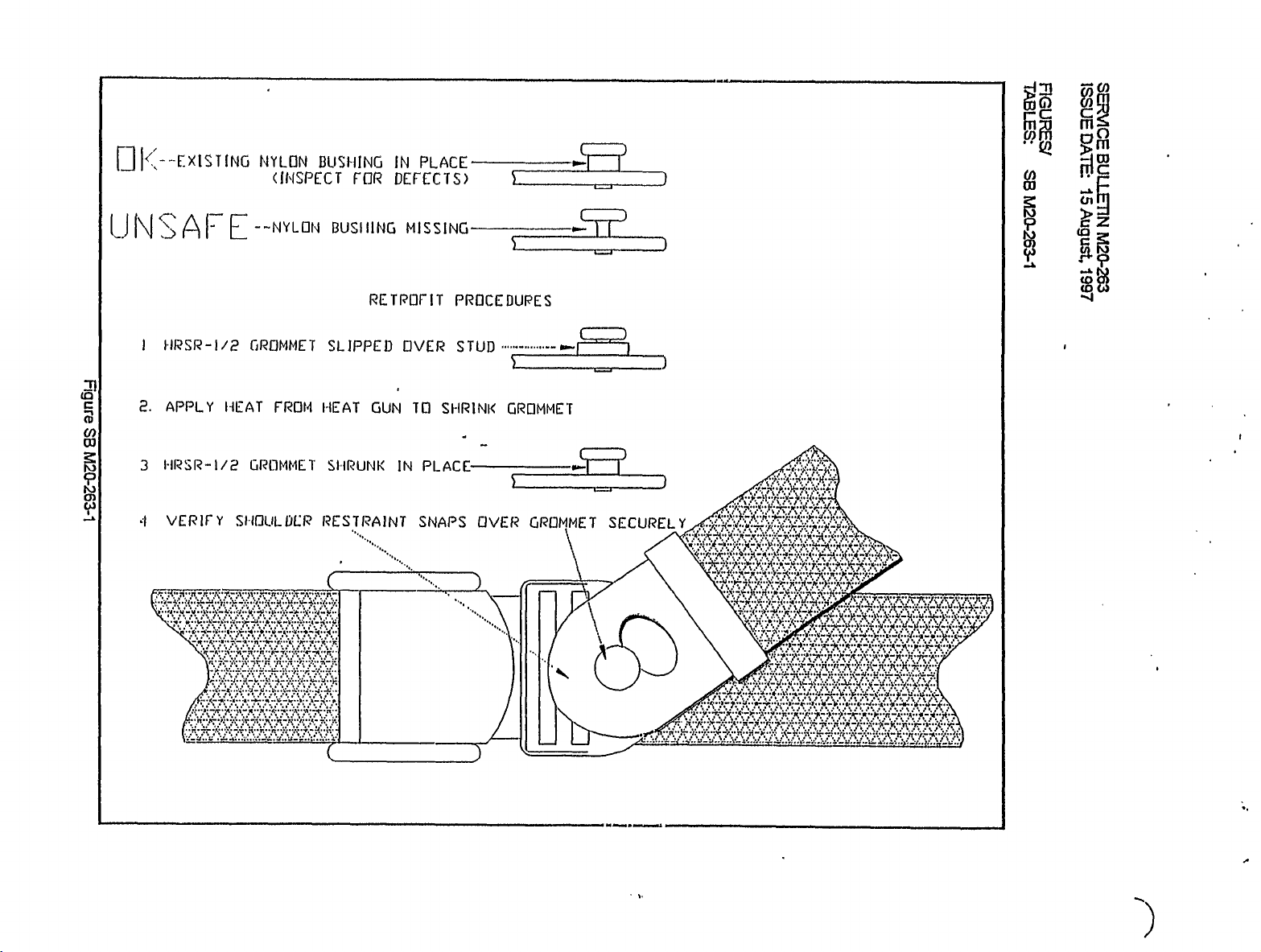
INSTRUCTIONS:
assembly.
VWRRANTY:
harness
restraints
Mooney
warranty
REFERENCE
DATA:
PARTS
Vendor
FIGURES/
TABLES:
UST~
lTEM
1
for
Refer
Service
claims
Grommet:
See
Figure
the
to
Mooney
aircraft
on
Center.
reiumed
are
FAA
Kit
Part
P/N
HRSR-1/2
Telephone:
Fax:
Figure
SE
hi120-263-1
illustration
Aircraft
still
k~our
account
to
General
number
XL
Technologies
1315
So.
Kernsvitle,
SE
M20-263
and
Corpoiation
WITHIN
Service
Aviation
SE
Park
NC
(910)
(910)
-1
on
depicts
follow
WARRANTY.
will
be
Parts
Airworthiness
M20-263-1
Dr.
27284
966-6777
9~6-2887
next
the
the
credited
conditions
procedures
will
allow
Department,
DESCRIPTION
GROMMET
page.
in
the
Alerts,
shown
0.5
The
normal
Kenviile.
that
hours
parts
AC
No.
may
on
laborto
will
manner
TX.
43-16,
the
be
be
found
figure.
inspect
available
when
No,
on
and
through
properly
210,
seat
any
repair
completed
January,
belt/restraint
the
your
1996
seat
beltl
QT/
4
t,
~I
I
II(
--EXISTING
I-_11
IJNSAFE--NILON
tlRSR-I/P
c
o,
2.
3
APPLY
HRSR-1/2
NEAT
i
4
VERIFY
SIIOULDCR
NYLON
(1I\ISPECT
T~RDMMES
FROW
~ROMMET
BUSI-IING
FOR
BUSIIING
SLIPPED
I´•IEAT
SWRUNK
RES7laAINT
I
I
IN
DEFECTS)
MISSING
RETPOFIT
OVER
GUN
Tn
IN
PLACE
S~-IRINK
PLACE
SNAPS
PROCEDUPES
STUD
GROMMET
OVER
GRUMMET
I I I
’Y
SECURELY
´•´•t,\ri´•\,
rnm
;OIC!
o
5m
oo
F
co
II
´•\,r,~
i.
i
\i’
I(´•´•i
1~
\t\
ii:
THIS
SERVICE
BULLETIN
ENGINEERING
IS
FAA
APPROVED
FOR
DESIGN
SUBJECT:
MODELSIS~
AFFECTED:
TIME
INTRODUCTION:
There
have
730005-1.
links
The
M20B,
M20L,
INSTRUCTIONS:
Remove
I.
Since
be
completed
numbers
part
M20C,M20D,
M20M
Iower
Aileron,
been
the
Aluminum
Smooth
Center,
M20B,
M20J
M20K
N120L
M20M
M20R
wn~in
reports
LH
in
accordance
be
to
M20E,
belly
fiberglass
Control
M20C,
S/N
S/N
ALL
S/N
S/N
nex~
of
a
RH
6
inspected
skin
to
Belly
24-0001
25-0001
SERIAL
27-0001
29-0001
25
crack
are
M20F,
gain
Skin
belly
Links
M20D,
hours
adjacent
very
with
are
M20G,
access
aircraft
aircraft
M20E,
THRU
THRU
NUMBERS
MRU
THRU
of
operation
similar,
instrudions
the
follows:
as
M20J,
to
Inspection
M20F,
24-3359
25-1999
27-0197
29-0042
to
the
weld
is
a
requested
M20K
underside
lst
skin
Forward
M20G
and
in
area
shown
of
of
aff
fiberglass
accordance
of
that
below.
aircraft:
nose
ALL
SERIAL
the
LH
an
inspection
730005-1
730051-501
wheel
skin
SERVICE
ISSUEDATE:
wil~
NOTE
aileron,
(LH)
well
NUMBERS
2
center
of
both
6
730006-000
6
(LH)
BULLETIN
1
February,
below.
control
of
these
730052-501
M20-264
link,
control
(RH)
1998
P/N
(RH)
ff
during
at
the
required
If
2.
a
ter,
from
3.
When
joint
angle
4.
Carefully
the
at
If
5,
no
Reinstallthe
6.
7.
If
discrepancies
6.
Connect
Maintenance
Visual
a
2nd
900angIe
for
visual
inspection
control
the
paint
(2nd
links.
area
and/or
from
joint.
inspect
weld
area,
discrepancies
e>dsting
If
existing
cordance
attaching
that
Note
be
to
Helm
the
good
with
are
Manual
inspection
joint
control
determines
location
inspected.
foreign
any
bean’ng),
resultsofthe
in
either
exist,
good
control
this
found,
bolts,
instructions.
from
the
dean
control
SE,
proceed
spacer,
is
determined
it
Helm
link.Wboth
proceed
that
there
of
spacer
maten~al
conduct
Magnetic
weld
or
area,
prime
links.
links
are
are
required
to
and
nuts
Lubn’cate
bearing,
links
between
have
a
Magnetic
in
the
not
PARTS
washers
NOTEQ
that
(link
have
to
step
are
no
been
Particle
adjacent
and
repaint
NOTEZ
replaced
at
each
LIST
Helm
either
has
been
9
thru
reinforcing
LH
RH
removed
Particle
Inspection
tube
area
at
this
annual
below.
in
accordance
bearings
control
been
replaced),
replaced,
11.
gussets,
control
from
the
Inspection
to
material.
(epoxy
time,
100
or
withTeffon
link
has
reassemble
remove
linksatattach
weld
area
of
each
determine
paint
recommended).
repetitive
hour
inspection
with
AC43-13
spray
a
reinforcing
further
no
LH
6
bolt.
of
the
link
on
if
any
inspections,
or
lubricant
inspection
skin
belly
RH
aileron,
Remove
900
2nd
that
2nd
discrepancy
in
thereafter.
per
Service
S
Mooney
gusset
is
and
cen-
paint
angle
90"
e~a’sts
ac-
3
M.
9.
10.
Verify
When
aiieron
rigging
rigging
verified
is
accordance
in
to
be
with
correct,
the
reinstall
proper
aircraft
section
aluminum
of
the
applicable
belly
skin
model’s
or
fiberglass
S
6
M
manual.
skin.
SERVICE
ISSUEDATE:
2of
Page
BULLETIN
2
1
February,
M20-264
1998
11.
Complete
WARRANP~
REFERENCE
DATA:
PARTS
MODEL’s
M20B,
M20E,
M20J,
LIST:
M20C,
M20F,
M20K
Logbook
KIT
Pi~
M20D,
M20G,
KlT
P/N
and
entry
2.0
hours
to
Up
Service
cordance
claimisreceived
Labor
Aircraff
ment
N/A
Center
with
and/or
Corporation
M20-264-1
DESCRIPTION
LINK,
LINK,
M20-26P2
return
labor
for
inspection
instructions
the
within
replacement
AILERON
AILERON
aircraft
and
cost
180
warranty
CONTROL,
CONTROL,
to
and
days
parts
policy
service.
of
replacement
replacement
of
this
SE
of
dateofthis
(if
needed)
for
LH
RH
aircraft
a
will
affected
will
parts
of
subject
in
still
SE.
be
not
aircraft
730005-1
730006-000
be
aileron
under
covered
are
PM
credited
warranty
under
beyond
to
control
warranty
the
Mooney
links
and
warranty
Mooney
in
agree-
QT/
1
1
ac-
M20L,
M20R
FIGURES/
TABLES:
M20M,
N/A
LINK,
LINK,
AILERON
AILERON
CONTROL,
CONTROL,
LH
RH
730051-501
730052-501
1
1
SERVICE
ISSUE
BULLETIN
DATE:
April
P~I20-265
1998
13,
SUB~ECT:
MODEU
AFFECTED:
TIME
MAIN
SM
OF
COMPLIANCE:
FNTRODUCTION:
which
have
been
Compliance
inspections
with
of
INSTRUC~IONS:
I.
Remove
applicable)
will
2.
Grind
limitations
cracks
lu120K
M20M
~1120R-
WITHIN
produced
this
this
part
have
LANDING
25-2018
27-0241
29-0135
This
Service
throughout
main
Service
be
to
s~inface
of
are
present.
THRU24-3416
NEXT
Service
laser
by
Bnlletin
landing
removed
the
of
Figure
CiEARLEG
25-2021
THRU
ONLY
29-0138
THRU
100
FLIGHT
gear
will
Iife
from
is
pattern
be
of
in
bracket
Bnlletin
beam
the
andMaintenance
510010
SB~u120-263-2.
510010
HOURS
being
cutting
considered
the
airplane.
accordance
XlanuaL
the
wheel
CEEgure
Alter
BRACI~
OR
in
issued
~nd
a
with
assembly.
SBrv120-265-1)
grinding
AT
effort
an
have
one-time
the
respective
is
It
not
CRACK
NEXT
to
exhibited
maintenance
necessary
inspect
REPAIR
MAINTENANCE
the
ensure
minor
design
smface
action
~20J,
to
open
Imlin’ne
witha10X
the
AC?ION
service
cracks
requiring
brake
Iines,
procedure
magnifying
life
in
no
or
but
and
glass
material
of
510010
additional
~1120R,
the
brake
adhering
to
ensure
at
as
to
brackets
the
bend
caliper
the
no
3.
1.
5.
6.
7,
WARRANTY:
REFERENCE
DATA:
PARTS
LIST:
those
For
areas
recommended)
new.
Re-install
as
Perform
Ivl20R
main
applicable)
Gear
as
applicable)
Complete
Mooney
issued
be
Service
M20T
Service
Service
~UII20M
~EV120R
N/A
Service
Service
affected
and
landing
Service
System
Airaaft
upon
Bulletin
the
(by
with
andwheels
gear
Maintenance
the
paint
and
Operational
Service
entry
and
showing
Corporation
of
receipt
and
andMaintenance
and
and
compliance
Maintenance
Maintenance
Maintenance
grinding
appropriate
Tnspection
Maintenance
compliance
card
will
Manual
Manual
Manual,
in
in
accordance
Marmal.
allow
cards
Manual
3),
step
fEyaway
in
accordance
Manual
with
8
hours
and
No.
No.133,
No.ljO,
No.
touch-up
SE
labor
warranty
122,
160,
prime
touch-up
with
the
with
M20-265
to
comply
forms
Sections
Sections
Sections
Sections
with
kit
paint
respective
the
respective
and
return
witi~
within
32-10-00
32-10-00
32-10-00
32-10-00
aa
epoxy
provided
~Z20J,
~vZ20J,
aircraft
this
Service
60
days
32-30-a
and
and
32-30-01
and
32-30-01
and
32-30-01
primer
with
the
PU120Y
Prl20K,
service.
to
Bulletin
the
of
1
(Sherwin
aircraft
~20h´•5
Pr120~
issue
dateofthis
Williams
when
or
Credit
~120R,
or
will
FIGURE
/TABLES:
SEE
FIGURES
SB~20-265-I
AND
SB~u120-265-2
that
follow.
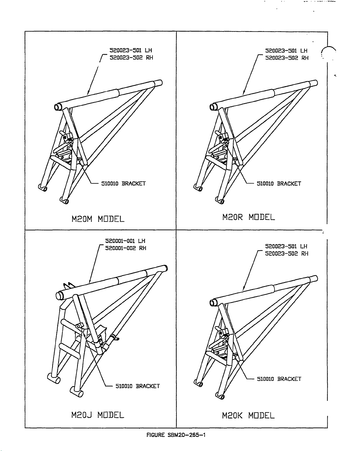
r
520023-501
520023-5(12
LH
RH
520023-501
LH
M20M
510010
MODEL
520001-001
BRACKET
LH
I
A
Y
r/
M20R
510010
MODEL
520023-501
BRACKET
LH
M20J
MDDEL
510010
BRACKET
FIGURE
SBM20-265-1
M20K
510010
MI7DEL
BRACKET
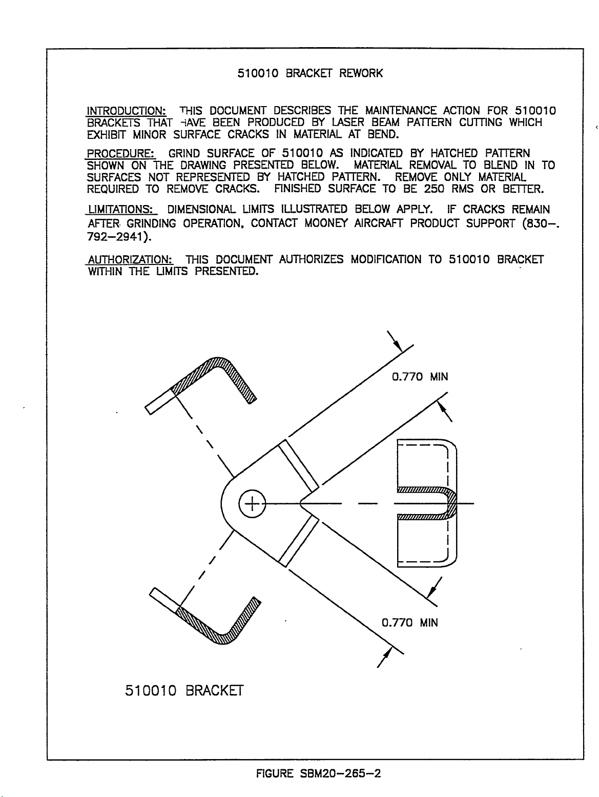
510010
BRACKET
REWORK
INTRODUCTION:
BRACKETS
MHIBTT
PROCEDURE:
SHOWN
SURFACES
MINOR
ON
REQUIRED
LIMTTATIONS:
AFTER
GRINDING
792-2941).
AUTHORIZATION:
WITHIN
THE
MAT
GRIND
7HE
NOT
TO
REMOVE
DIMENSIONAL
UMITS
iAVE
DOCUMENT
BEEN
THIS
SURFACE
SURFACE
DRAWING
REPRESENTED
CRACKS.
OPERATION.
DOCUMENT
MIS
PRESENTED.
PRODUCED
CRACKS
OF
PRESENTED
BY
UMTTS
CONTACT
DESCRIBES
BY
IN
MATERIAL
510010
BELOW.
HATCHED
FINISHED
ILLUSTRATED
MOONfl
AUTHORIZES
THE
LASER
AT
AS
INDICATED
MATERIAL
PATTERN.
SURFACE
BELOW
AIRCRAFT
MODIFICATION
MAINTENANCE
BEAM
BEND.
REMOVE
TO
APPLY.
0.770
PATTERN
8Y
REMOVAL
BE
PRODUCT
ACTION
HATCHED
ONLY
250
IF
TO
510010
MIN
CUTTING
TO
RMS
CRACKS
SUPPORT
FOR
WHICH
PATTERN
BLEND
MATERIAL
OR
BETTER.
REMAIN
BRACKET
510010
IN
(830-.
TO
5100~0
BRACKET
/C\
0.770
I__J
MIN
FIGURE
SBM20-265-2
THIS
SERVICE
BULLETIN
IS
FAA
APPROVED
FOR
ENGINEERING
DESIGN
SUBJECT
Revision
MODELS
TIME
A
S/N
OF
COMPLIANCE:
INTRODUCTION:
MAC
received
tive
in
both
EATON
and
ble
This
worthiness
INSTRUCTIONS:
actuators
aircraft
1.
2.
3.
personnel
Service
Remove
M20R
Refer
for
for
Send
listed
removing
removal
Avenue,
4.
When
dance
05.
Verify
5.
When
tn’es
have
WARRANTY:
Mooney
Aircraft
Service
Complete
REFERENCE
If
compliance
EATON
identical.
PARTS
actuator
The
LIST:
prepared
AFFECTED:
M20J
M20K
M20M
M20R
SPARES
a
report
normal
within
above
Bulletin
Directive
the
aircraft.
the
to
and
actuator,
El
Segundo,
inspected
with
procedures
Landing
Landing
been
Corporation
Centei
and
DATA:
with
reinspected
AD
will
Mooney
PIN
560254-507,
to
correct
24-3414,
25-2017,
-27-0241,
29-0136,
ARAPAHOE
BEFORE
of
failure
the
and
emergency
have
requested
manufacturing
and
retumed
supersedes
be
to
issued
one
piece
applicable
and
installing
installation
freight
CA,
actuator
Gear
Gear
Rigging
completed.
for
removal
return
MAC
MAC
have
A
been
Revision
N/A
Aircraft
S/N
24-5418
25-2024
affected,
Corporation,
27-0245,
29-0141
AERO,
of
modes.
that
lots
the
on
skin
belly
MAC
Service
the
of
the
prepaid,
90245,
is
received
in
the
applicable
Rigging
is
recommends
of
the
standard
Special
B
to
or
in
accordance
complied
(EATON
THRU
THRU
THRU
NEKT
a
landing
actuators
on
to
EATON
MAC
this
subject
on
actuator.
actuator)
to
Eaten
Attn.:
is
in
verified
actuator
Warranty
Letter
SL
98-2
Inspection
PM
102000-7)
deleted
24-3423
25-2029
27-0246,
29-0152
ENGLEWOOD,
FLIGHT
actuator.
gear
within
either
side
for
inspection.
Special
M20J
8
by
accordance
that
with
Letter
within
8
Maintenance
(MAC
Corporation,
Mr.
Thai
maintenance
MAC
or
corrected,
the
affected
for
shipment
claim
Revision
98-2,
has
been
with
this
using
M20K
of
SIN
27-0243,
27-0247,
the
same
of
the
subject
98-2,
the
next
aircraft,
Manual,
SI
M20-52,
Aerospace
Pham.
personnel
Service
8
with
return
aircraft
to
including
B,
accomplished
Service
either
the
REVISION
EATON
corrected
27-0248,
CO.
-EATON
This
failure
manufactun’ng
actuator
Revision
few
weeks.
and
SECTION
Revision
Maintenance
of
all
SECTION
aircraft
be
EATON
freight
dated
Bulletin.
MAC
SERVICE
A
Landing
27-0249
ACTUATOR,
rendered
lot
A
or
forward
the
A
Controls
from
to
taken
to
for
their
charges.
1
December,
it
is
not
The
instructions
SL
98-2A
DATED:
Gear
to
include
lot
be
removed
B.
32-30-05
B
or
can
Division,
EATON,
Manual,
32-30-00
service
authorized
an
requested
necessary
orBor
BULLETIN
Actuators,
the
landing
as
belly
also
re-install
SECTION
after
1998.
1
December,
MAC
S/N
27-0248.
S/N
1044
gear
the
subject
from
the
skin
on
on
procedures
be
referred
2338
in
procedures.
Logbooks
Mooney
inspection.
have
to
and
intent
SE
M20-266A.
M20-266A
inopera-
actuator
applica-
M20M
Alaska
accor-
32-30-
en-
the
are
1998
I
I
8
to
FIGURES/
TABLES:
N/A
MOONEY
LOUIS
AIRCRAFT
SCHREINER
THIS
CORPORATION
FIELD
SERVICE
BULLETIN
SERVICE
IS
FAA
APPROVED
BULLETIN
FOR
ENGINEERING
Revision
Revision
NUMBER
DATE:
B:
1
C:
DESIGN
S.B.
15
February,
15
August,
September,
M20-273
2000
2000
2000
Revision
Revision
Revision
completely
SUBJECT:
MODELS/S/N
TIME
INTRODUCTION:
A
B
C
M20M-
M20R-
M20S
COMPLIANCE:
OF
FIELD
hours
INSPECTION
Mooney
automatic
to
determine
line
FAA
replacement
To
Drawing
coming
Mooney
Once
repetitive
INSTRUCTIONS:
SECTION
Secure
i.
for
2.
Remove
Remove
3.
interior
4.
For
5.
Inspect
from
Disconnect
6.
complete
7.
Inspect
LH
8.
Inspect
looking
SE
is
prepared
is
~reoared
is
orepared
through
MOONEY
AFFECTED:
S/N:
SIN:
SIN:
INSPECTION,
every
Aircraft
operations
MAC
and
facilitate
months.
Factory
aircraft
the
100
aircraft
the
aircraft
side
inspection
Wing
inside
access
Wing
Main
RH
Wing
from
M20-273-1.3.
to
clarify
to
clarify
delete
to
the
oroduction
M20M,
27-0274THRU27-0282
29-0189THRU
30-0026
100
flight
REPAIR,
Corporation
if
improper
in
March,
machine,
riveting
personnel
2
within
aircraft
020021,
inspection
aircraft
Inspection
Service
have
hour
inspections
I:
in
being
Pilot
Go-pilot
lower
LH
panels
below
orientation,
leading
the
cabin,
and
LH
to
Rib
Landing
Rib
inside
LH
wording
ins~ection
M20M,
line
M20R,
M20S,
THRU
(Instruction
hours
(lnstruction
has
there
riveting/assembly
1999,
have
of
been
will
in
Center
the
accordance
repaired
years
accordance
inspected.
seats
RH
interior,
windows,
refer
Rib
edge
for
working,
RH
main
landing
gear
Assemblies,
Gear
Wheel
Assemblies,
Main
RH
of
SE.
locations
27-0273
SIN
to
orior
29-0209
30-0042
Section
thereafter.
determined
are
were
determined
aircraft
and
possible
scheduled
be
MAC
or
shown
with
from
kick
LH
to
Assemblies,
loose
landing
bay.
PIN’s
Wells
T/E
Landing
No
~rocedural
automatic
the
AIRFRAME
i.)
Limit
Section
some
components
processes,
used
during
that
licensing.
repair
with
Approved
at
the
factory,
under
applicable
tracks.
seat
panels
RH,
SE
Figure
rivetsorrivets
gear
Clean
interior
210022-1
for
P/N’s
only,
Gear
and
reauired
from
INSPECTION
At
next
2
years
II.)
duetothe
that
the
some
the
into
this
TIME
sections
to
gain
may
M20-273-1.0.
PIN’s
inboard,
(LH)I-2
working
210022-3
Wheel
changes
Models
rivet
maintenance
from
2
years
which
manufacture
of
in
accordance
Mooney
Service
Field
in
accordance
OF
COMPLIANCE
access
be
removed
210026-509
seeping
wheel
of
landing
or
made.
were
reoetitive
Affected
machine
inspections
list.
discre~ancies.
action,
of
date
License.
of
date
from
possibilityofimproper
that
were
the
components
Bulletin
Service
of
the
require
Factory
incorporated
of
with
shall
Center.
with
MAC
for
inspection
desired.
if
inspection.
these
MAC
Service
will
Service
(LH)I-510
fuel
per
door
actuation
wheel
gear
(RH),
(Station
loose
rivets
per
(LH)/-4
Wells
for
(RH),
working
Records
not
License.
components.
may
Rivet
be
performed
MAC
no
(RH),
Figure
mechanism
wellofdirt
21.125),
Figure
(Wing
loose
or
oer
show
exceed
to
The
into
require
Installation
Center
Drawing
longer
Maintenance
below.
5
(Wing
SE
looking
SE
Station
FAA.
this
SIN
20
operation
inspection
the
production
repair
the
over
the
at
020021,
be
required.
The
Sta.
M20-273-1.1.
to
gain
and
grease.
from
M20-273-1.2.
59.25),
rivets
per
was
flight
of
an
is
or
Repair
the
manual
complete
24.50),
inside
Figure
SERVICE
ISSUE
Revision
PAGE
BULLETIN
DATE:
2
C:
of
9.
LH
Inspect
15
1
September,
7
RH
seeping
If
10.
working,
331-3880
(800)
11.
Complete
to
form
the
date
12.
Complete
addition,
COMPLIANCE
M20-
FEBRUARY,
Main
Main
fuel
per
the
Customer
MAC
of
this
entry
the
list
273
2000
Spar
Landing
Figure
loose
or
schedule
to
enclosed
Service
in
aircraft
information.
2000
Assembly
Gear
M20-273-1.4.
SE
leaking
aircraft
Inspection
Support
Bulletin.
Airframe
hourmeter
Refer
Web
Wheel
rivets
Department,
Log
time
to
Stiffeners,
Wells
are
found,
into
Factory
Form
Book
when
the
following
for
with
Attn.:
stating
P/N’s
working
contact
Service
all
SE
compliance
next
inspection
recommended
210000-17
loose
or
Mooney
Center
requested
M20-273
(LH)I-18,
rivets
Customer
for
information.
Inspection
to
MAC
is
due
logbook
and/or
repair.
Service
per
SE
entry.
(RH),
any
Support
Return
Data,
Bulletin
M20-273
looking
rivets
immediately
this
within
M20-273.
TIME
from
inside
potentially
completed
60
days
OF
at
of
In
DATE
Aircraft
M20-273.
S
13.
in
SECTION
1.
determine
process.
2.
downtime.
WARRANTY:
SECTION
Mooney
complete
inspections
creditofsix
is
SECTION
Mooney
repair
between
REFERENCE
PARTS
LIST:
HOURMETER
been
has
Prior
020021
ig
accordance
the
natu
re___________________________________________________
the
Once
Mooney
the
The
repair
Aircraft
the
done
through
Aircraft
or
replacement
owners
DATA:
to
next
aircraft
with
II:
Customer
current
schedules
I:
initial
required,
(if
man
(6)
II:
inspected
completionofrepairs
scheduled
this
Corporation
inspection
hours.
a
Mooney
Corporation
and
N/A
N/A
this
inspection
has
been
M20-273,
SE,
Support
hours
flight
willbecoordinated
will
and
to
Warranty
Service
will
the
at
Mooney
MAC
and
in
date
repaired
personnel
accumulated
allow
and
log
be
done
Center.
perform
Factory
the
aircraft
credit
compliance
in
accordance
be
will
in
accordance
are
no
be
will
at
time
a
one
book
entry
in
conjunction
will
the
arrives
on
longer
contacting
in
order
the
convenience
warranty
described
be
necessary
Service
in
with
with
before
or
with
required.
to
with
honored
Center
agreement
Mooney
Mooney
Hourmeter
MAC
owners
schedule
of
credit
SECTIONIof
in
100
hour
ONLY
inspection
when
Aircraft
Aircraft
drawing
of
the
the
aircraft
of
ten
inspections)
when
and
schedules
to
these
Corporation
Corporation
Service
Drawing
reading_______________.
applicable
into
in
hours
this
SE.
will
are
field
the
repair
order
time
Subsequent
allow
with
component
established
inspections
aircraft
to
minimize
to
warranty
M20-273
SE
#020021,
above
aircraft
owners
man
(10)
compliance
required
any
schedules.
Bulletin
to
FIGURESITABLES:
Reference
Figures
SE
M20-273-1.0,
1.1,
1.2,
1.3,
1.4
the
on
following
pages.

ISSUE
SERVICE
DATE:
Revision
BULLETIN
15
FEBRUARY,
1
C:
September,
M20-
PAGE30f7
273
2000
2000
NOTE:
LnplN
*WN
fP~IR
o.sO
M41N
147.7$
2
(LR61RH)
FIGURE
SYMBDLS
AAE
REMOWU.
WS
INSPEGT
INSPECT
FOR
WS
INSPECTION
FROM
SIATIDN
INSIOE
STATION
R14T
THIS
Wi
BPZII
ool--IQI
(7
O
SE
REPRESEM
INSPE~IDN.
OAI~ION
ORIENTATION
21.125
BOTHLH6t
24.50
Z*5D
AND
RIB
ACCESS
PANELS
51A
21.125
r/
5025
WS
IQ
2130
ASSI.
Ol~fRhU
OLICReM
STATION
HH
O
LNIDINO
FROY
29.21
INSII)E
UPR
LWR
GV1R
AIB
M20-273-1.O
IN
SURF/ICE
D
SURFACE
PSSYS.
WHEEL
C~8(N.
THESE
WS
N*W
DO
25.B5
(LR~RH)
SPPA
NUT
REPUIRE
2(.125
ws
(LFldrRH)
ME
WING.
W9
laJ.s
11´•7.75
ANI3
YIELLS.
-9
-10
POSSIBLE
(51
WEB
OPP
-15
-23
STIFFENER
-11
-12
STIFFENER
OPP
-14
-13
STIFFENER
OPP
STIFFENER_
OPP
-16
-19
-20
CAP
OPP
210035-7
210035-8
a
a
,oe*
’I+O+*
CAP
-21
OPP
SIDE)
-22
210026-509
(LH)/
-510
DEFECT
PL
EACH
-33
-34
(RH)
99
WEB
OPP
RIB
ASSY
9
$6~
LE~DINC
210~37-7
210037-8
EDGE
(STA
OPP
24.50)
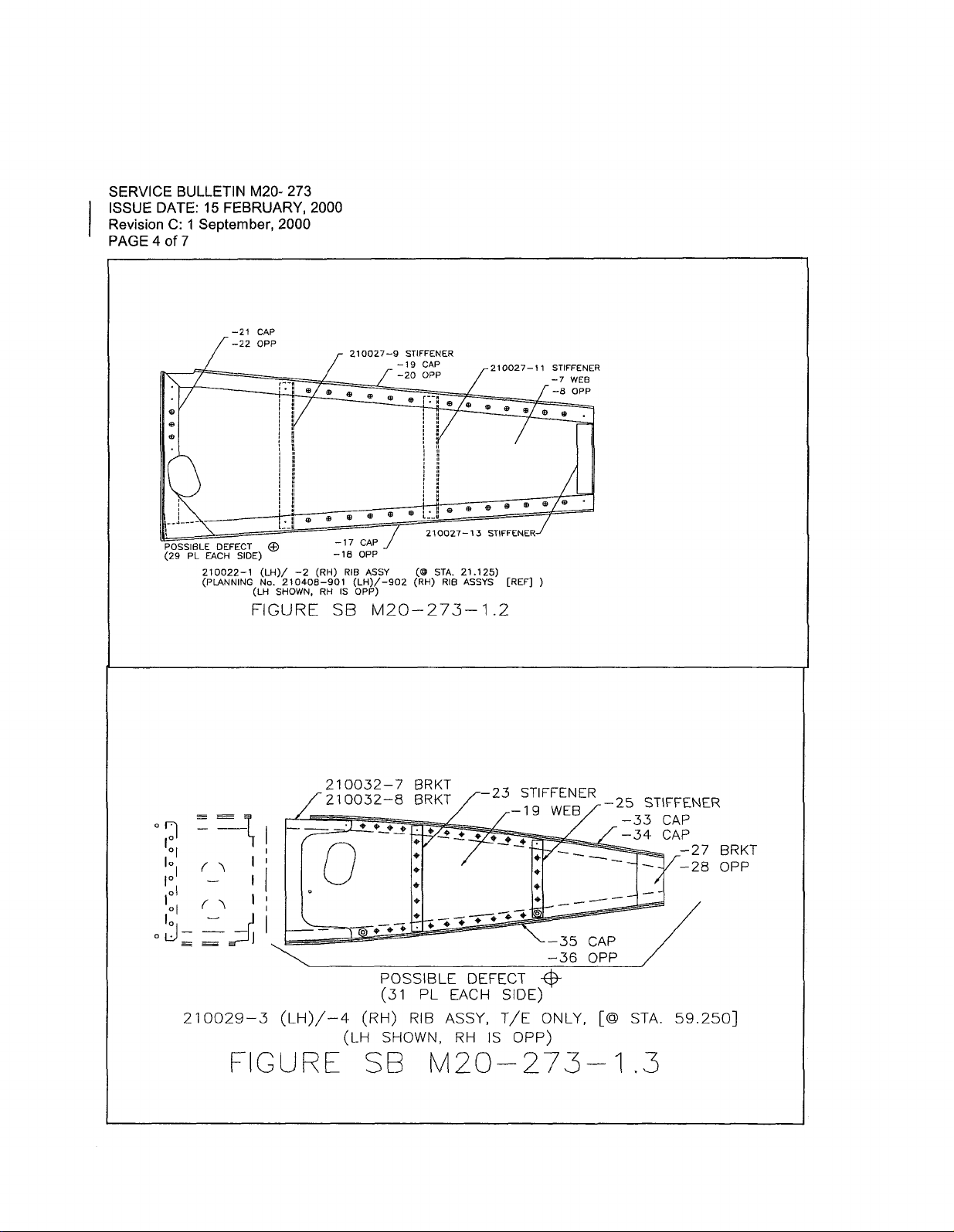
SERVICE
ISSUE
Revision
PAGE40f7
DATE:
C:
BULLETIN
15
1
September,
M20-
FEBRUARY,
2000
-21
CAP
-22
OPP
:1‘1
273
2000
210927-9
STIFFENER
--19
-20
CAP
OPP
210027-11
’?e
STIFFENER
-7
WEB
-B
OPP
POSSIBLE
(29
ol
I"
I":
.5,
DEFECT
PL
EACH
210022-1
(PLANNING
f\
f
210029-3
:__I
SIDE)
-2
(LH)/
No.
210408-901
SHOWN,
(LH
FIGURE
I
i
1
(LH)/-4
FIGURE
I
-17
-Is
(RH)
RH
SE
210032-7
210032-8
O
RIB
(LH)/-902
IS
OPP)
(LH
CAP
OPP
t+O-0
(RH)
´•1__1"
ASSY
M20-273-1.2
o
I´•
POSSIBLE
(31
RIB
SHOWN,
SE
210027-15
STA.
(O
(RH)
BRKT
BRKT
C’--9t3
PL
M20--
21.125)
RIB
ASSYS
EACH
ASSY,
RH
STIFFENER
-23
p_+~´•
DEFECT
IS
[REF]
STIFFENER
-19
SIDE)
T/E
OPP)
273-’1
WEB
-35
-36
ONLY,
-25
CAP
OPP
[O
ST\FFENER
-34-33
CAPCAP
STA.
59.250]
.S
BRKT
28
OPP
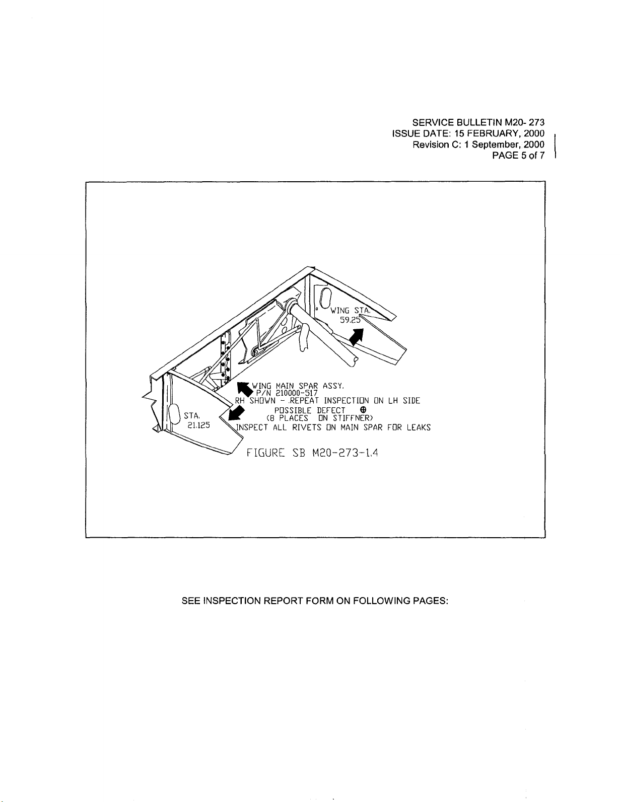
ISSUE
SERVICE
DATE:
Revision
BULLETIN
15
FEBRUARY,
1
C:
September,
M20-
2000
2000
PAGE5of
273
7
STA.
21.125
tWING
P/N
SHOWN
RH
~INSPECT
FIGURE
MAIN
210000-517
-.REPEAT
POSSIBLE
PLACES
(8
ALL
SPAR
RIVETS
SE
Q
WING
ASSY.
INSPECIION
DEFECT
ON
STIFFNER)
ON
59
MAIN
STA;
SPAR
ONLHSIDE
FOR
LEAKS
SEE
INSPECTION
REPORT
FORM
ON
FOLLOWING
PAGES:
 Loading...