

Page 1
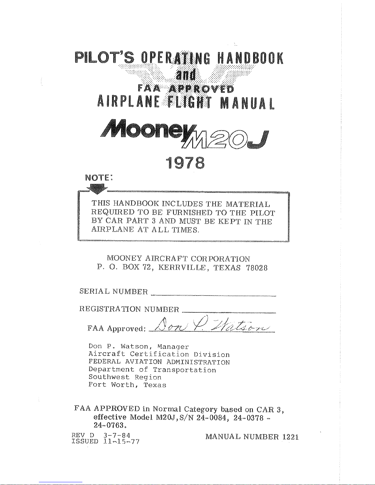
Page 2

Page 3
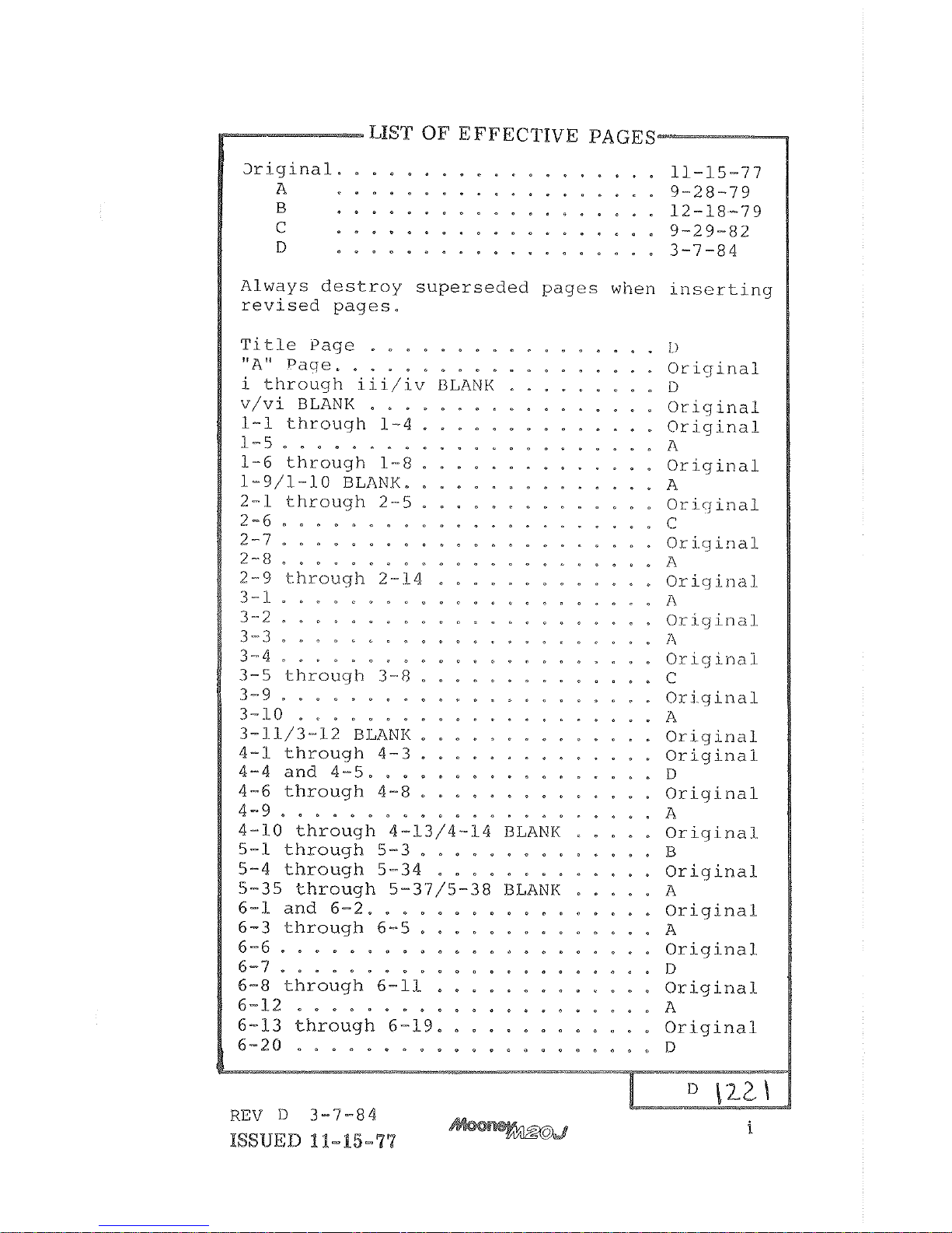
Page 4
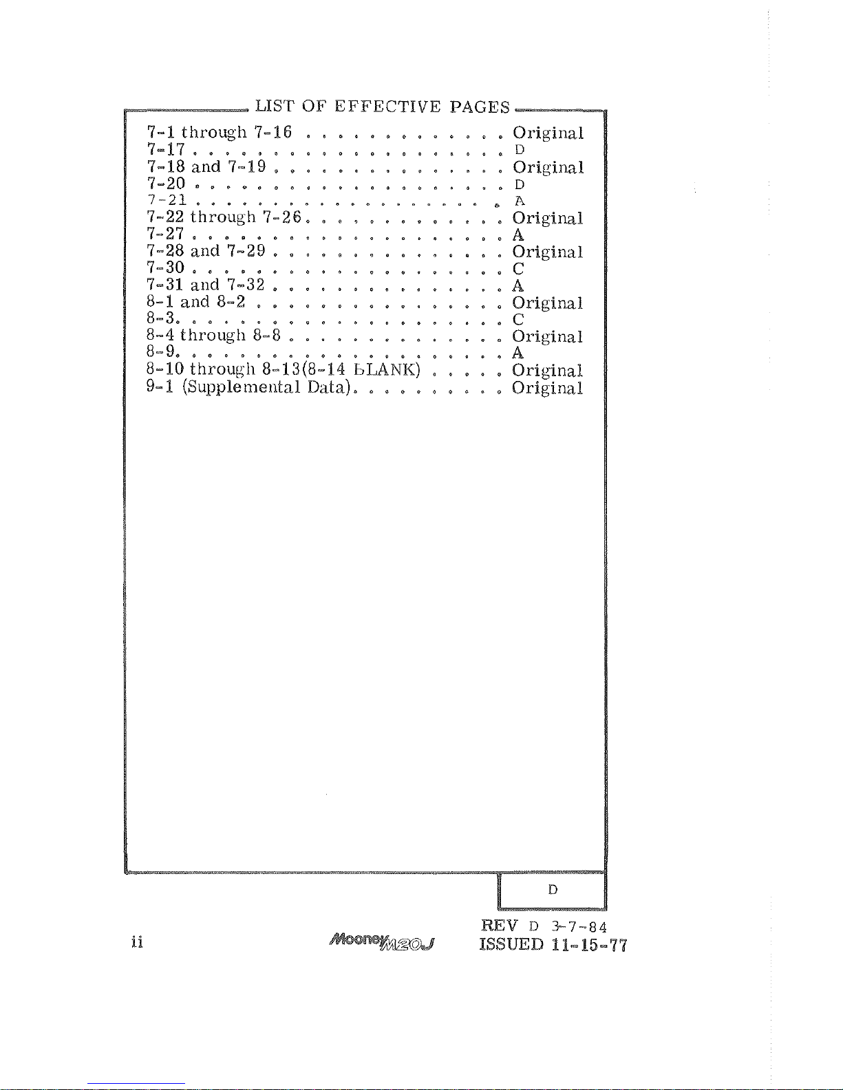
Page 5
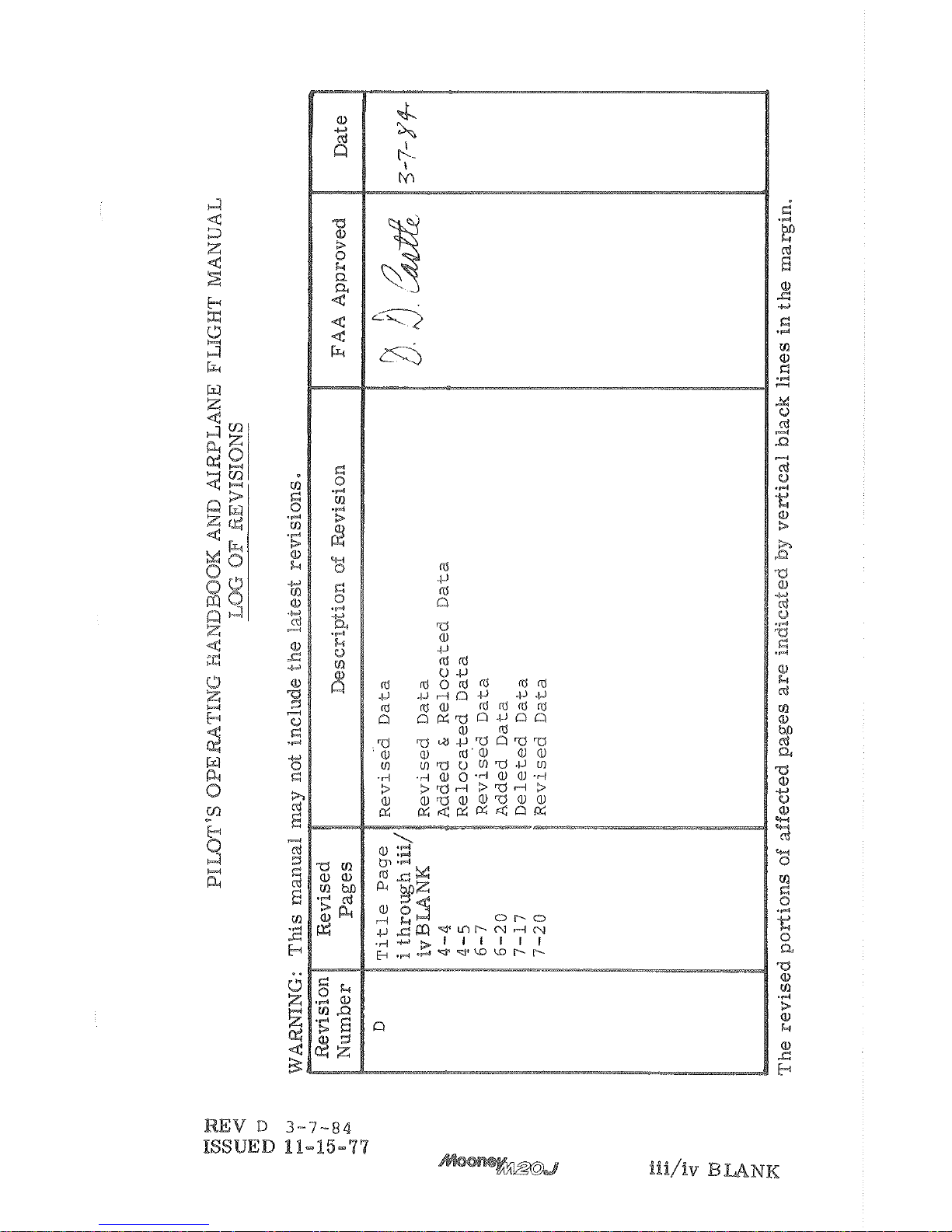
Page 6

Page 7

CONGRATULATIONS . . .
WELCOME TO MOBNEYvS NEW DIMENSION IN SPEED
MOONEY
AN
ELITE AND DISTINC
-
TIVE CLASS
OF
AIRCRAFT OWNERS.
WE HOPE
YOU FIND YOUR NEW MOONEY A UNIQUE FLYING
EXPERIENCE, WHETHER
EVER.
is
provided as an operating guide for the
Mooney
201,
Model
--
regardless of your previous experience--
carefully
read the handbook from cover to cover and review it
frequently.
on the latest
publication approval.
The
is
reserved to make
without notice*
Every effort has been
in
a
and conveniea2t
manner to enable you to
the
as
a
ready
reference,
in
and content recommendations
is
solicited.
THE
Page
of this manual
is
a "List
of Effective Pages
"
containing a complete etarent listing of aXB pages
,
Original or Revised. Also, in the lower
corner of the outlined portion,
a box which denotes
the issue or revision of the
revision to the manual a new List of Effective Pages
be received to replace the previous one*
This handbook will be kept current
by
Mooney Aircraft
handbook
has
been filled in and mailed to Mooney Aircraft
Corporation,
Box
72,
11-15-77
Page 8

Page 9
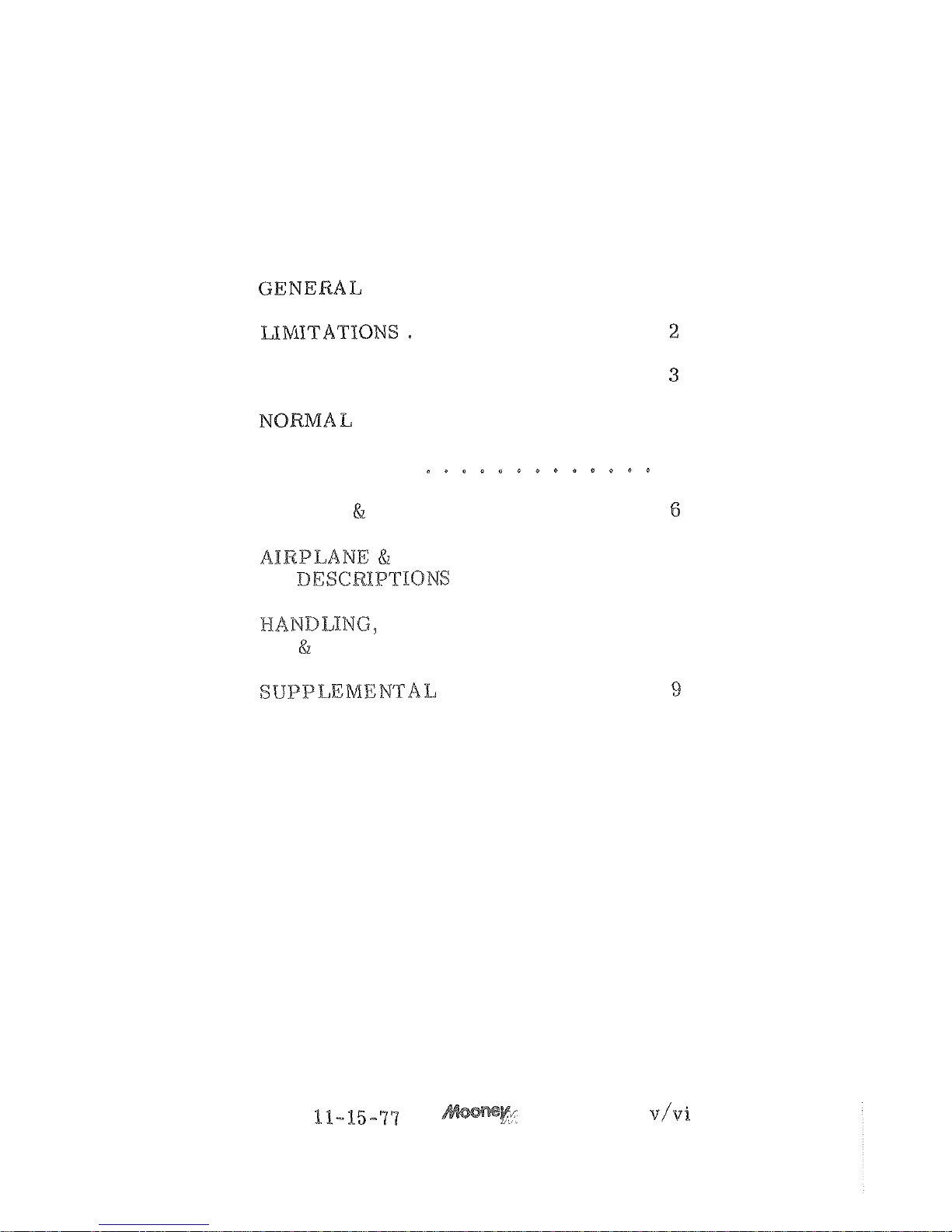
TABLE
OF
CONTENTS
SECTION
................
a
.............
......
EMERGENCY PROCEDURES
........
PROCEDURES
4
PERFORMANCE
5
..........
WEIGHT
BALANCE
SYSTEM
...........
7
SERVICE
.........
MAINTENANCE.
8
........
ISSUED
.
4
BLANK
Page 10

Page 11
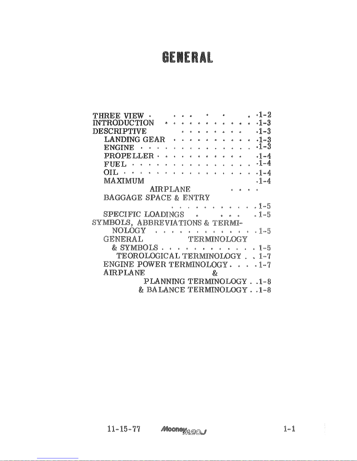
SECTION
I.
TABLE
OF
CONTENTS
TITLE
PAGE
. .
.
.
.
.
DATA
.
WEIGHTS
STANDARD
WEIGHTS
1-5
DIMENSIONS,
.
.
.
AIRSPEED
ME
FLIGHT
WEIGHT
ISSUED
Page 12
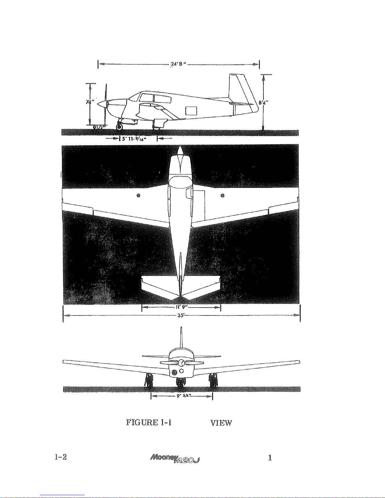
THREE
ISSUED
1-15-77
Page 13
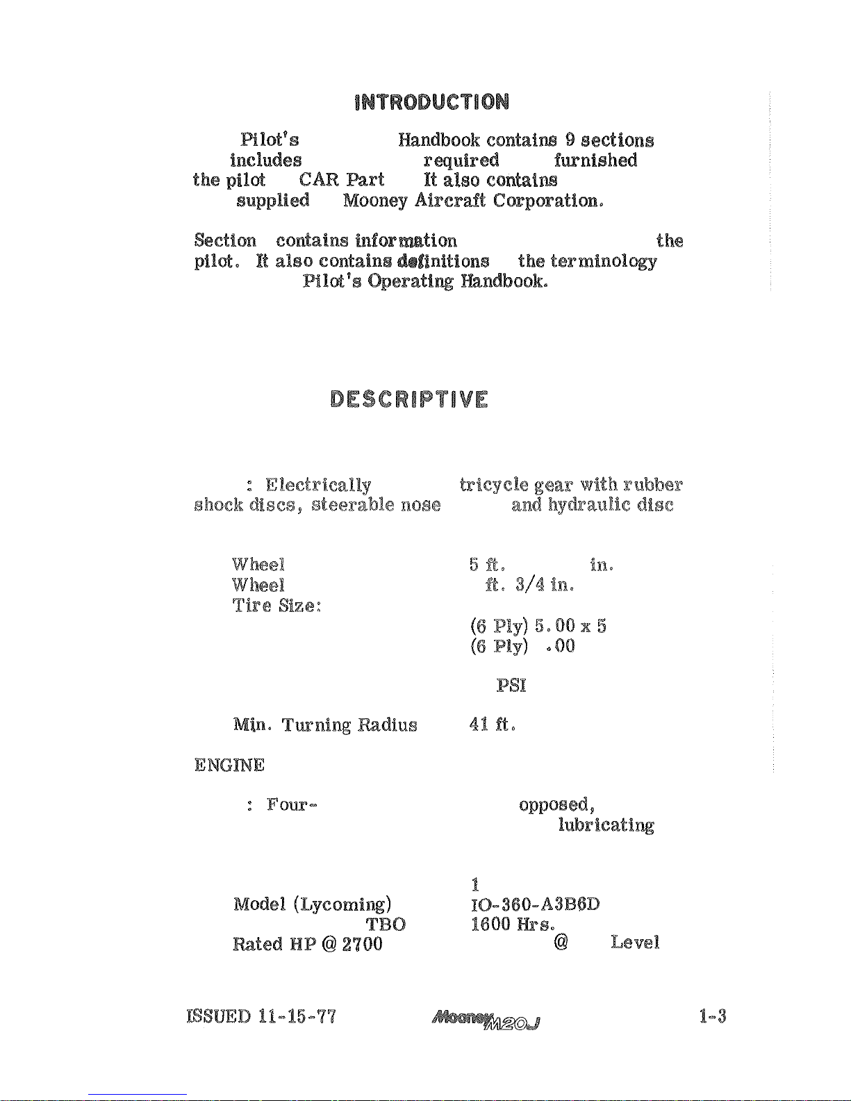
This Rlot
Operating hndbsok contaim
and includes the material rquired to be fwnished to
by
3.
data
by
I
used in this Pilot's 9eratiq andbook.
DATA
LANDING
GEAR
TYPE
operated
wheel,
brakes.
Base
11-9/16
Tread
9
Nose
Main
6
x
6
Tire Pressure:
Nose
49
Main
30
PSI
(No Brakes Applied)
TYPE
air
cooled,
and fuel
-
injected engine with a wet-sump
sys
-
tem.
Number
of
Engines
Recommended
RPM
200
BNP
Sea
Page 14
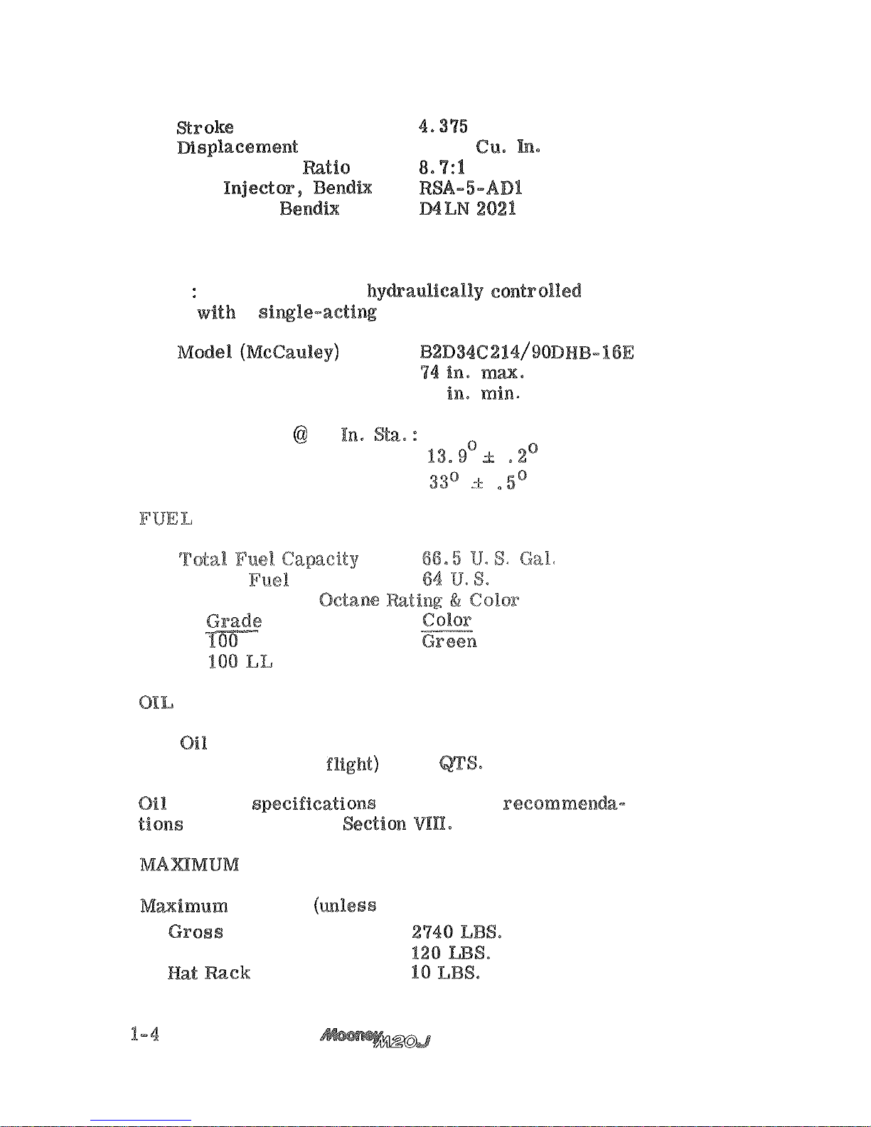
Bore
5.3125 in.
361.0
Compression Ratio
Fuel Injector, Bend&
Magnetos, Bendix
PROPELLER
TYPE
Constant- speed, hy&aulically controlled pro
-
peller with
a
Diameter
73
Number
of
Blades
2
Blade Angle
30
Low
Nigh
Usable
Capacity
Gal.
Minimum
Fuel
Blue
Capacity
(6
QTS
MIN for
8
are
contained in Seetion
CERTIFICATED
WEIGHTS
Weight
Baggage
Area 120
ISSUED 11-15-77
Page 15
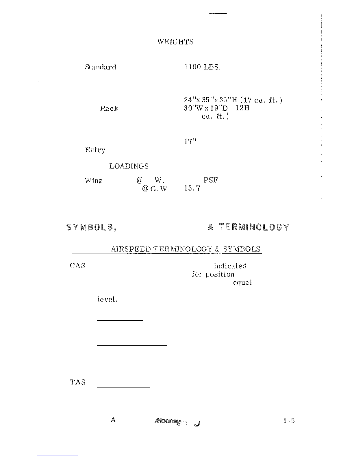
STANDARD AIRPLANE WEIGIlTS
Basic Empty Weight
(See page
6-4)
BAGGAGE SPACE' AND ENTRY DIMENSIONS
Baggage Area
Hal Rack
x
(Max.)
(2.6
Baggage Door Opening
Above Ground
(Sill)
46
"
Entry Width
20.5
"
SPECIFIC LOADINGS
G.
16.4
Power Loading
PHP
ABBREVIATIONS
GENERAL
Calibrated Airspeed means the ia~dicated speed
of an aircraft, corrected
-
ment error. Calibrated airspeed is equal to
true airspeed in standard atmosphere at sea
GS
Ground Speed is the speed of an airplane
relative to the ground.
IAS
Indicated Airspeed
is
the speed of an aircraft
as shown on its airspeed indicator. IAS values
published
in
this handbook assume zero instru
-
ment error.
True Airspeed is the airspeed of an airplane
relative to undisturbed air.
REVISION
Page 16
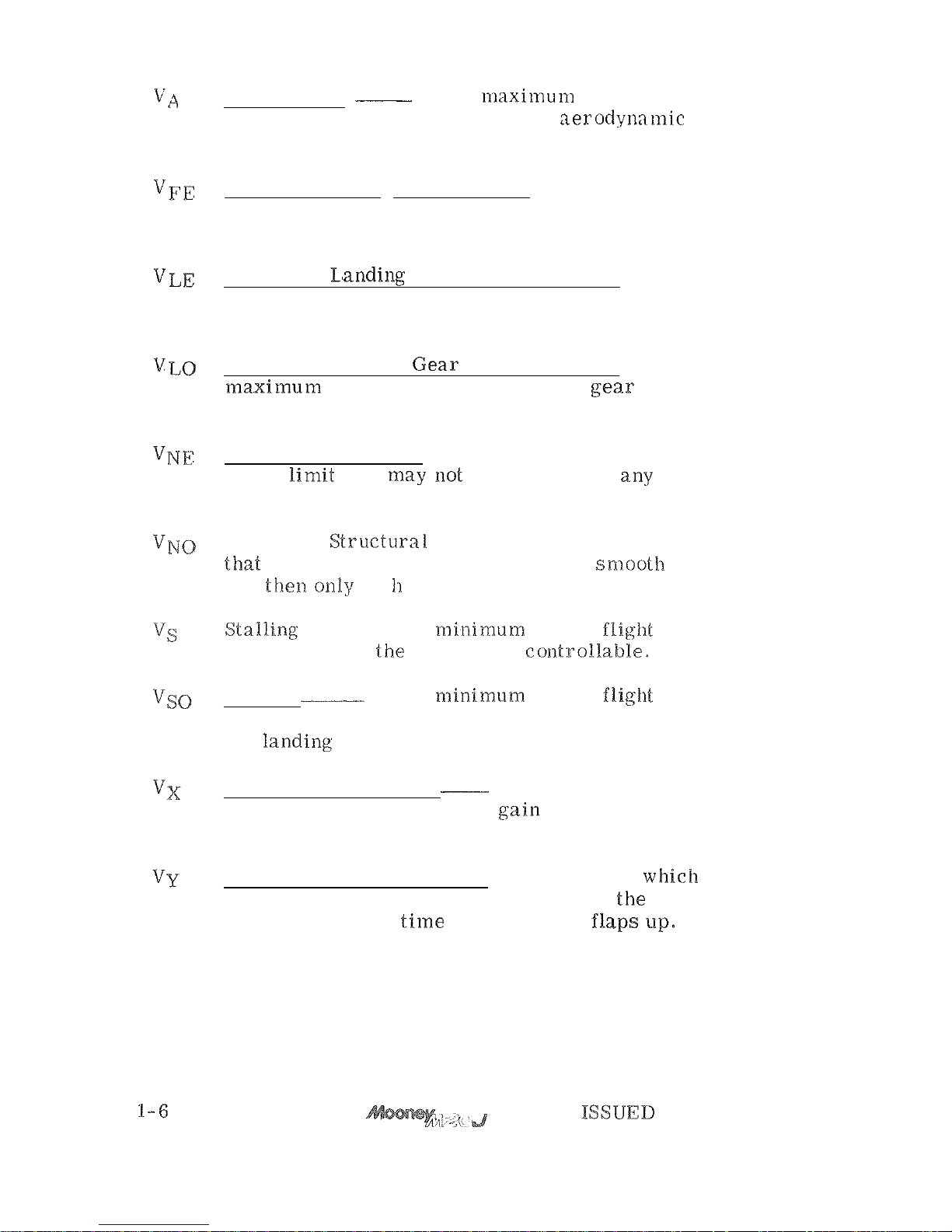
Maneuvering
Speed is the maximuin speed at
which application of full available
control will not overstress the airplane.
Maximum Flap Extended Speed is the highest
speed permissible with wing flaps in a pre
-
scribed extended position.
Maximum
is
the
maximum speed at which an aircraft can be
safely flown with the landing gear extended.
Maximum Landing
is
the
be safely extended or retracted.
Never Exceed Speed or Mach Number is the
speed
time.
Maximum
in
air
and thela only wit
caution.
speed at which tlae airplane is contm-obkable.
Stalling
Speed or the rni.nimum steady flight
speed at which the airplane is controllable in
the
Best Angle
-of-
Climb Speed
is the airspeed
which delivers the greatest
in
the shortest possible horizontal distance.
Best Rate
-of-
Climb Speed is the airspeed which
delivers the greatest gain in altitude in tlae
shortest possible time with gear and flaps
11-15-77
Page 17
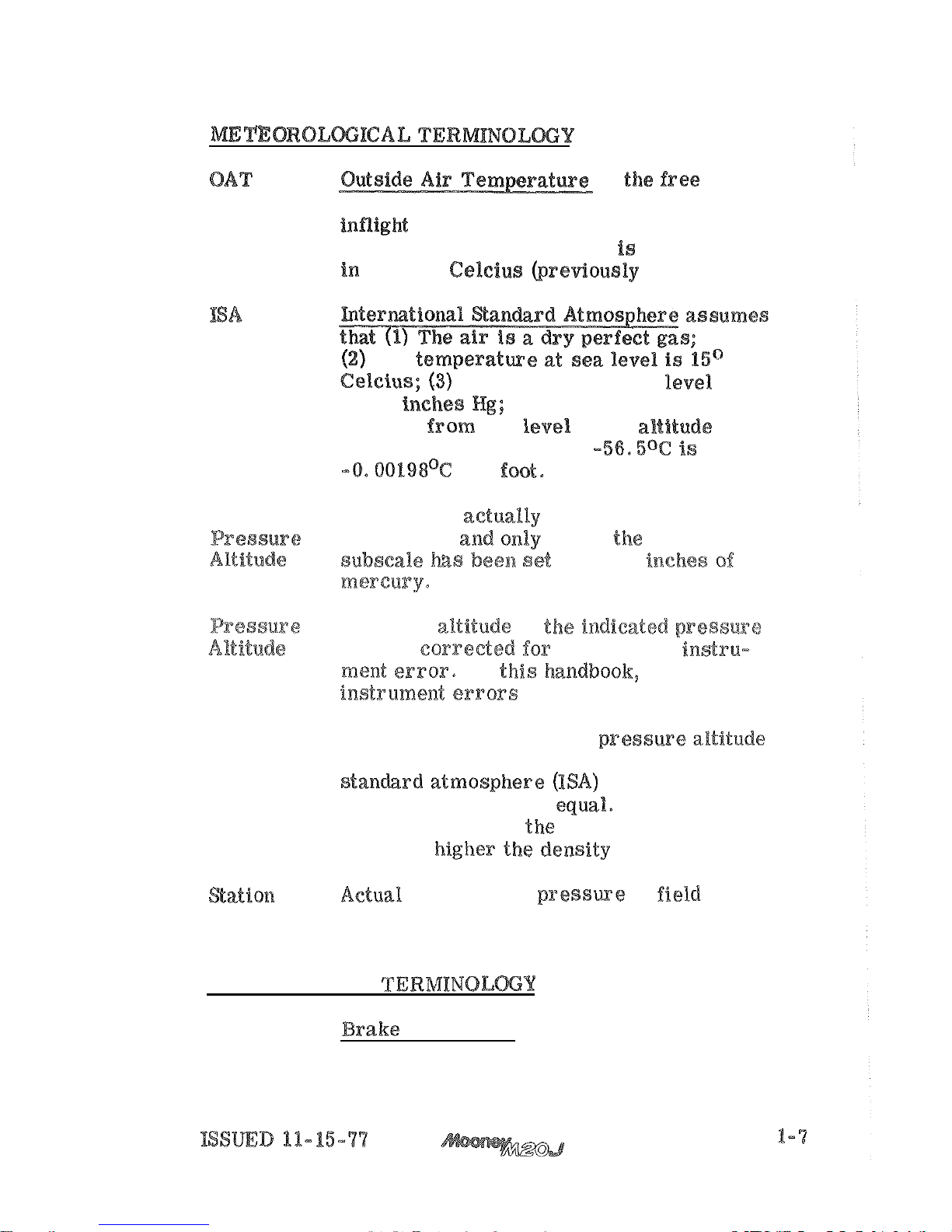
is
air
static temperature, obtained either from
meteorological sources. It
expressed
The
The pressure
at
sea level
is
29.92
(4)
The
temperature
gradient
sea
to the aanfteads at
which the temperature
is
per foot.
Indicated The number
read from
an
alti
-
meter when
when,
barometric
to
29.92
Pressure altitude
is
altitude corrected
position
and
In this handboolc, altimeter
assumed
to
be
zero.
Density Altitude
as
determined
by
Altitude and existing ambient temperature.
In
density and
pressure altitude are
pressure altitude,
the
tempera
-
ture, the
atmospheric
Pressure elevation.
ENGINE
POWER
BHP
is
the power developed
by the engine.
Page 18
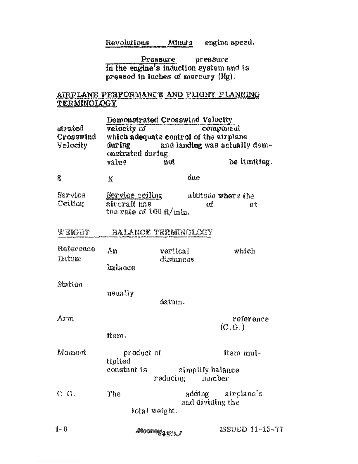
RPM
is
MP
Manifold Reaeure
is
a
ax
-
Demon
-
is
the
the crosswind component
for
takeoff and landing wae actmlly
certification tests.
The
shown
is
considered
to
is
the acceleration
to
gravity.
is
the
the capability
climbing
AWD
imaginary vertical plans from
all horizontal distances
are
measured
lor
purposes,
A
location along the airplane fuselage
the reference
The horizontal distance from the reference
datum to the center of gravity
of
an
The prduct of
the
weight of an item
arm.
(Moment divided
by
a
used
to simp%i$gv balance cal
-
culations
by
of
digits.
)
.
Arm
arm obtained
by
individual moments
sum
by
the total wsigkat.
Page 19
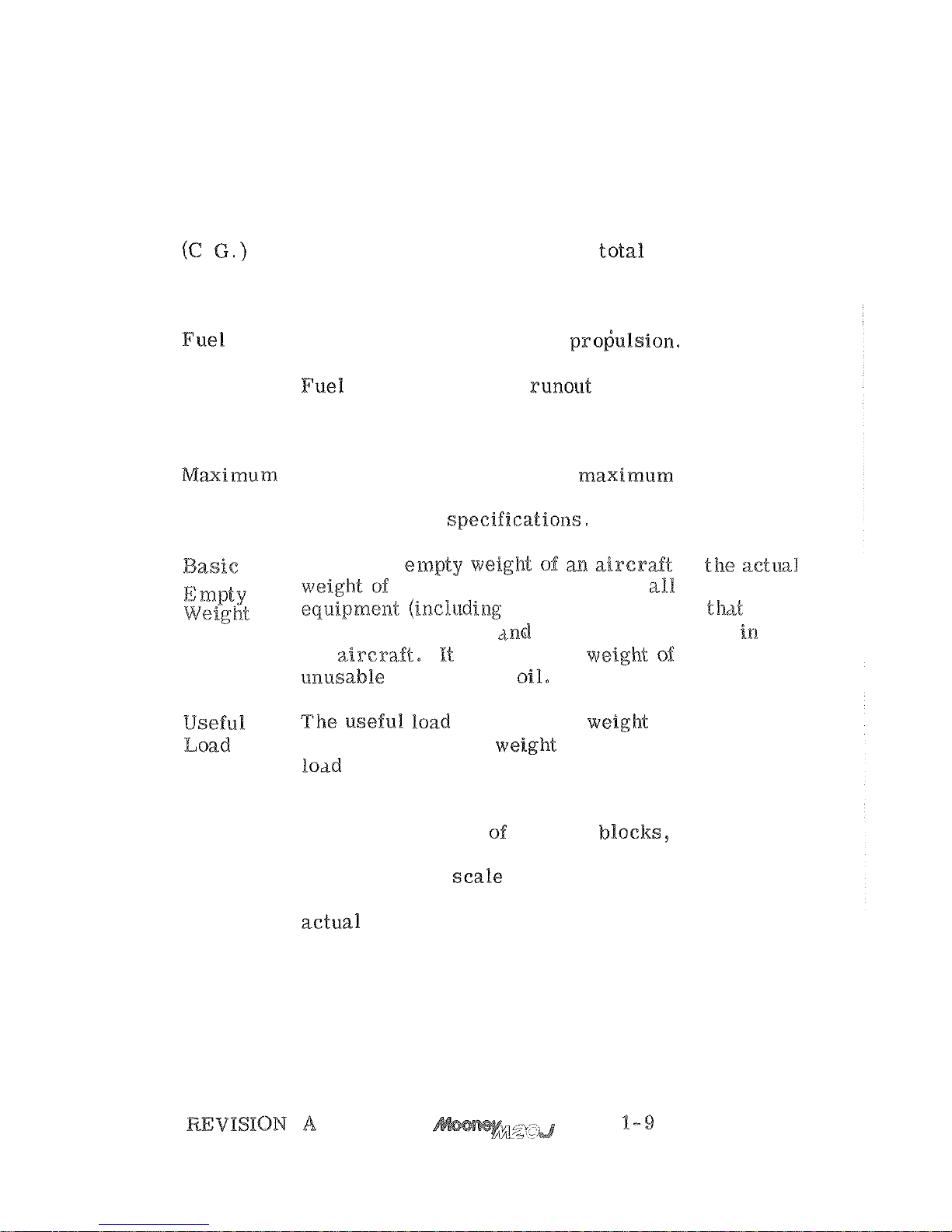
C.G.
The
extreme center of gravity locations within
Limits which the airplane must
be
operated at a given
weight.
Center of
The point at which an airplane would balance if
Gravity suspended. Its distance from the reference
.
datum is found by dividing the total moment
by
the total weight of the airplane.
Usable
Fuel available for airplane pro;ulsion.
Unusable
Fuel
completed in accordance with governmental
regulations.
The maximum weight is the maximum authorized
Weight weight
of
the aircraft and its contents as listed
in the aircraft
The
basic empty weigh"c. of
is
and
includes all operating
has a fixed location and
is
actually installed
the airc-sa.ft. It includes the weight
the
is
the empty weight subtracted
fuel, passengers, and baggage,
Tare
Tare is the weight
etc. used when weighing an airplane, and is
included
in
the scale readings.
Tare is de
-
ducted from the scale reading to obtain the
(1-10
Blank)
Page 20

Page 21

.
TABLE
OF
TITLE
INTRODUCTION
2-2
AIRSPEED
2-3
ED
INDICATOR
2-4
.
POWER
LIMITATIONS
2-5
POWER
PLANT
INSTRUMENT
2-6
WEIGHT
CENTER
OF
2-7
MANEUVER
LOAD
FACTOR
2-9
O
PERATI
O
N
2-9
INSTRUMENTS
AND
.
.
2-9
...............
2-10
INTERIOR
2-10
2-13
FAA
APPROVED
-15-
77
Page 22
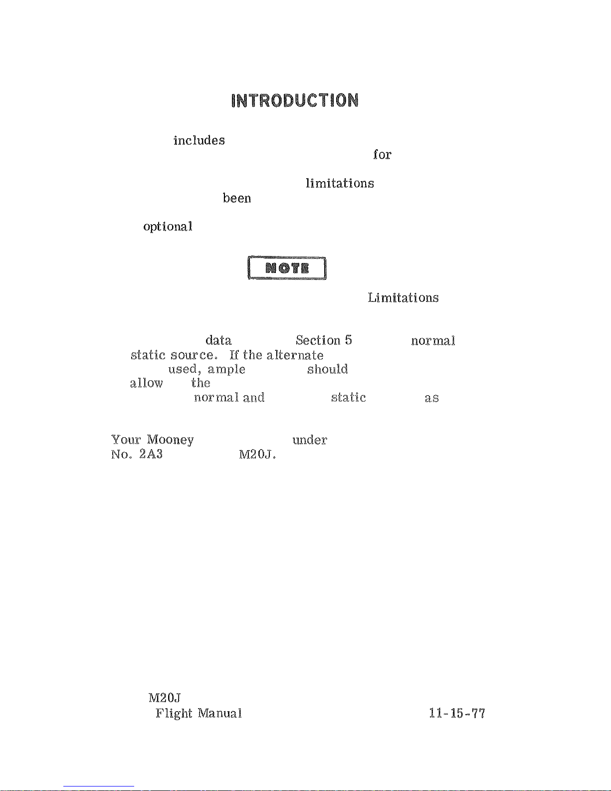
Section
2
markings, and basic placards necessary
operation of the airplane, its engine, standard sy sterns
and standard equipment. The
this section have
Administration. When applicable, limitations associated
with
are included in Section
9.
The airspeeds listed in the Airspeed Limitations
chart (figure 2-1) and the Airspeed Indicator
Markings chart (figure
2-2)
are based on Airspeed
Calibration
with the normal
being
to
for
airspeed calibration variations be
-
tween the ~aormal and
alternate
shown
in
Section
5.
is
certificated under
FAA
Type
Certificate
as Mooney M20J0
Mooney
Airplane Flight Manual
FAA
APPROVED
ISSUED
Page 23
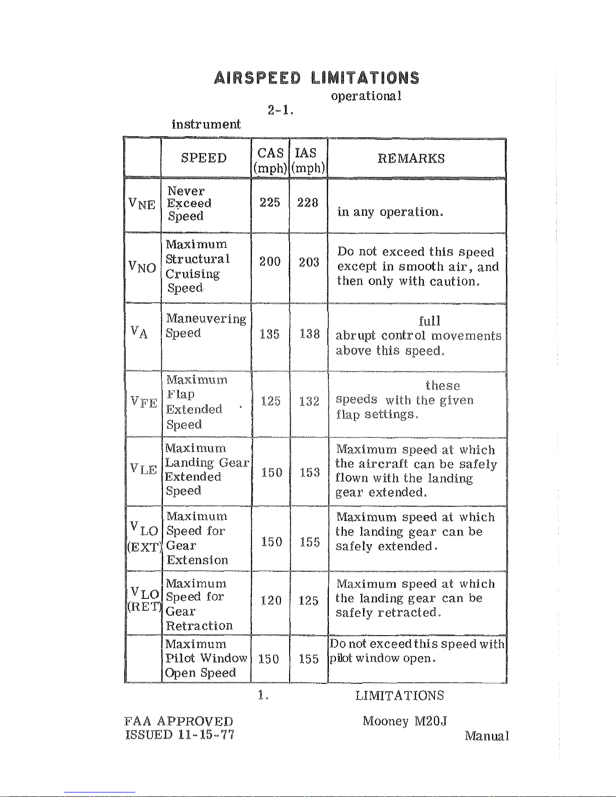
Airspeed limitations and their operatiom% significance
are shown in Figure
This calibration assumes
zero
Do not exceed this speed
Do not make
or
Do
not
exceed
FIGURE
2
-
AIRSPEED
Airplane
Flight
2-3
Page 24
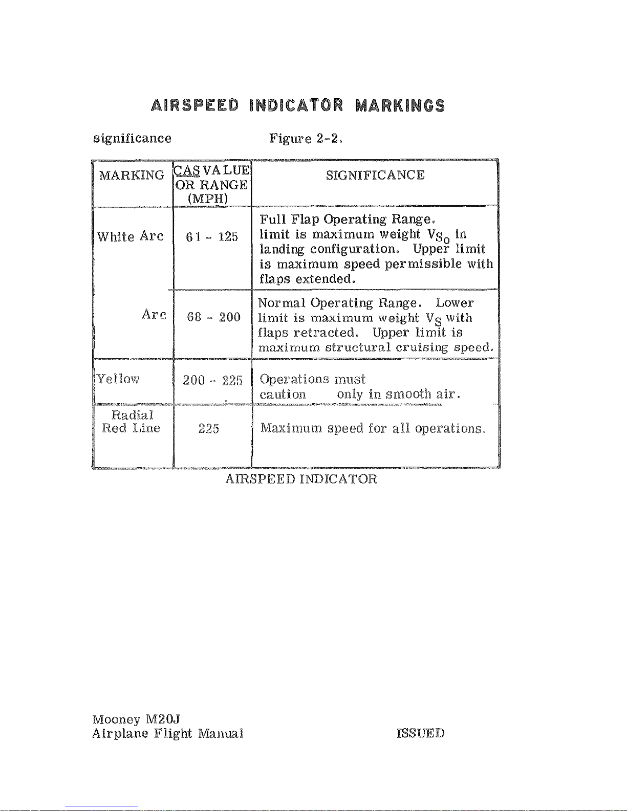
Airspeed indicat or mar kings, their color code and operational
Green
Arc
be
conducted
with
and only-
_..---*
-
FIGURE
2-2.
2-4
FAA
APPROVED
11-15-77
Page 25
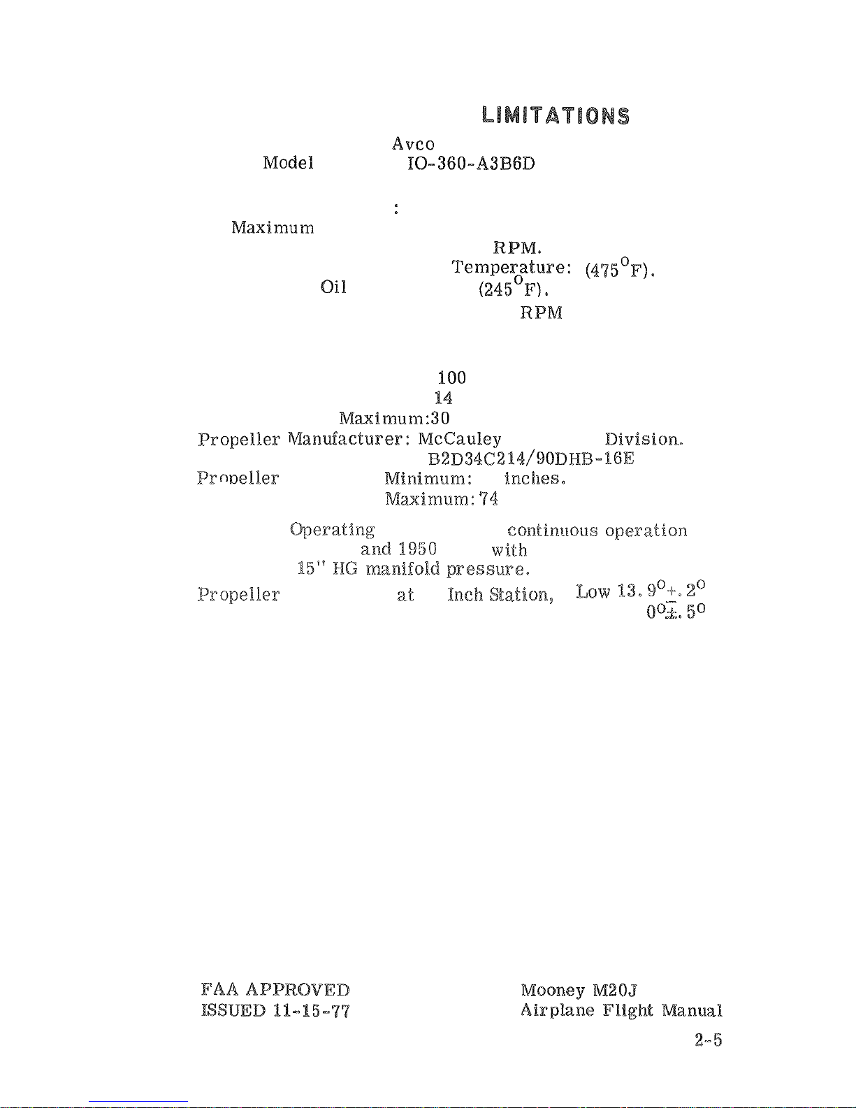
POWER
PLANT
Engine Manufacturer: Avco Lycoming.
Engine
Engine Operating Limits for Takeoff and
Continuous Operations
Maximum Engine Speed: 2700
Maximum Cylinder Head Temperature: (4~5'~).
Maximum
Temperature: (24~~~).
Transient Engine RPM Limit - 2970 RPM for
3
Seconds or Less
Oil
Pressure, Minimum:
25
psi.
Maximum:
Fuel
Pressure, Minimum:
psi
Propeller Model Number: ~2%)3462%4/90~~~-16E
93
inches,
Propeller Operating Limits: Avoid contineeous operation
between 1500 and
RPM
power
settings
below
Angle
38
High
33.
Page 26
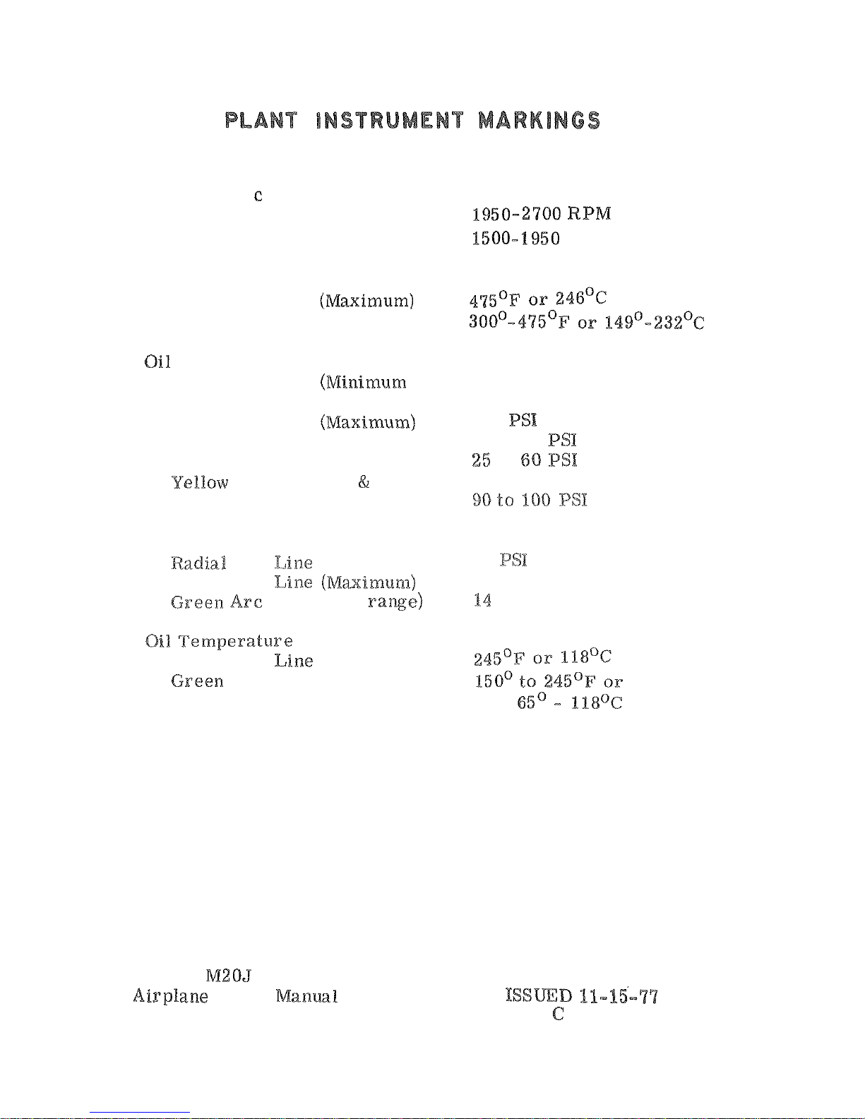
POWER
Tachometer
Radial Red Line (Rated)
Green
Ar
--
(Rated
operating range)
Yellow Arc (Caution Range)
Cylinder Head Temperature
Radial Red Line
Green
Arc
(Operating range)
Pressure
Radial Red Line
idling)
Radial
Wed Line
Green
Arc
(Operating range)
Yellow
Arc (Idling range)
Arc
(Starting
warm-up range)
Fuel
Pressure
Red Line
(Minimum)
Radial
Red
(Operating range)
Radial
Red
Are
(Operating range)
Mooney M205
Flight
2-6
2700
RPM
25
PSI
aoo
60
to 90
to
14
30
PSI
to
30
PSI
FAA
APPROVED
REV
9-29-82
Page 27
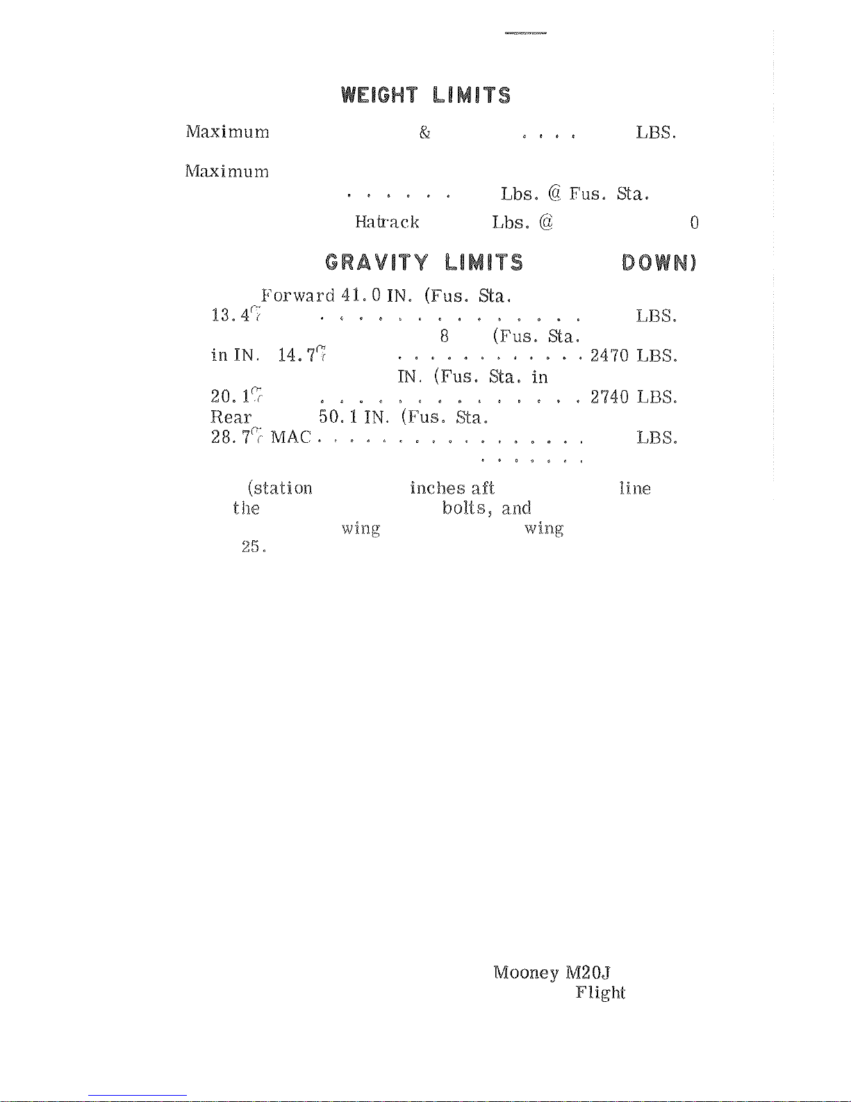
Landing)
2740 LBS.
in
Baggage
Compartment
120 Lbs.
Maximum
Weight
in
.
10 Lbs.
Fus. Sta. 119.
CENTER
OF
(GEAR
Most Forward 41.0
in
IN.
)
MAC
2250 LBS.
Intermediate Forward 41.
IN. (Fus, Wa.
)
MAC.
Forward Gross 45.0
.)
MAC
in IN.)
2740 LBS.
MAC
(IN.
at
Wing
Wa.
93-83)
59.18
Datum
is
5
of the center
of the nose
gear
attaching
33 inches
forward
of
the
'leading
edge
at
station
59.
FAA
APPROVED
ISSUED 11
-15-
77
Airplane
Manual.
Page 28

MANEUVER LIMITS
This airplane must be operated as
a
airplane.
obatic maneuvers , including spins, are
not approved
.
Extreme sustained sideslips may result
in
fuel venting
thereby causing fuel fumes in the cabin.
Prolonged sideslips, steep descents,
or
of power if the selected fuel
tank
con
-
tains less than
48
(8
Up
290-foot
may
at
above 190
MPH
IAS
Above 190
(164
rapid throttle seduction may re
-
sult
in
momentary propeller
RPM
Mooney
FAA
REVISION
Page 29
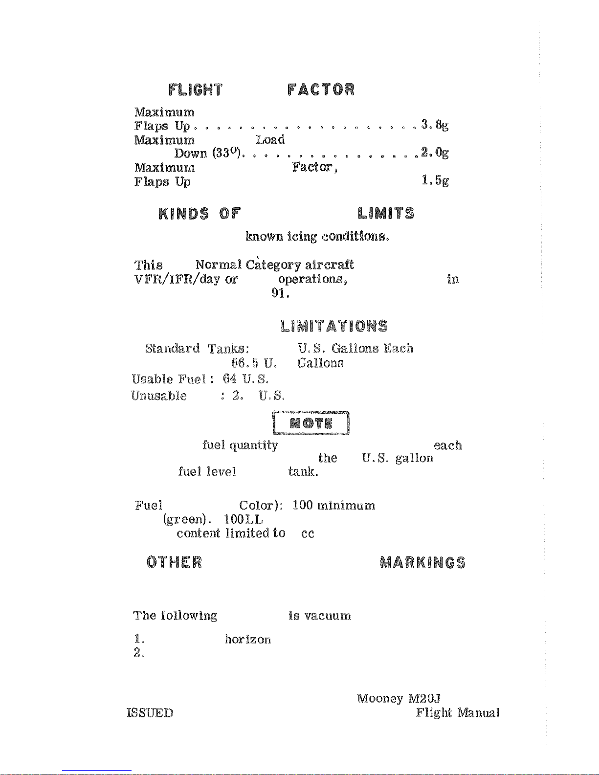
LOAD
LIMIT3
Flaps
...................
OPERATION
Do not
operate
in hown ici~ conditions,
is
a
when
quipped
accordance with
FAR
FUEL
2
93.25
Total Fuel:
8.
Gallons
Fuel
5
Gallons
A
reduced fuel qmntity indicator
is
installed
in
lank,
These
indicators show
25
usable
in each tank
fuel
(low lead) aviation fuel (blue) with
a lead
2
is
also
approved,
INSTRUMENTS
AND
operated:
Artificial horizon
Directional gyro
FAA
APPROVED
11-15-97
Airplane
Page 30
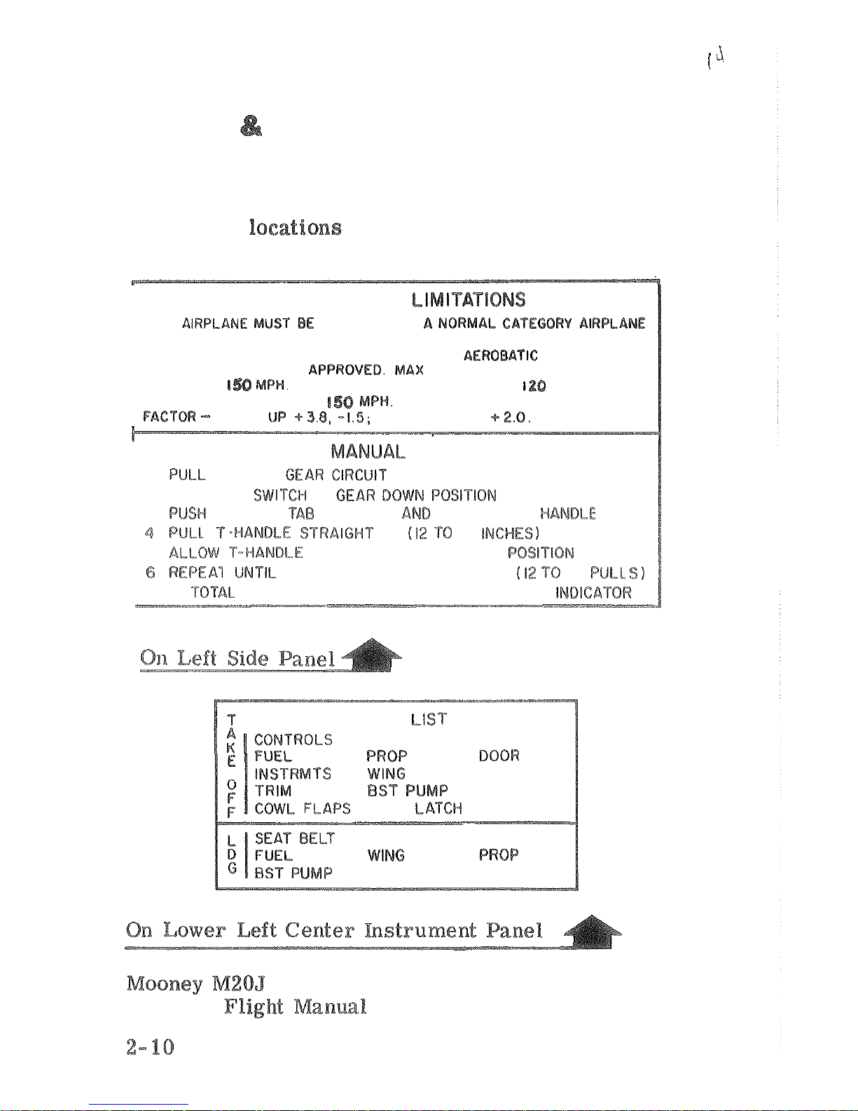
DECALS
PLACARDS
INTERIOR:
The
following
placards
must
be
installed
inside
the
cabin
at
the
specified.
OPERATIONAL
T
H
I
S
O
PER
A
TED
A
S
IN COMPLIANCE WITH
THE
OPERATING LIMITATIONS STATED IN
THE
FORM
OF
PLACARDS,
MARKINGS AND MANUALS. NO AEROBATIC MANEUVERS,
INCLUDING SPINS, AWE
EXTENDED,
MPH.
MAX
SPEED TO EXTEND GEAR,
MAX
MANEUVERING
FLIGHT
LOAD
FLAPS I1P
EMERGENCY
GEAR
EXTENSION
I
2
PUT GEAR SWITCH IN
3
REL
E
A
S
E
F
O
RWA
R
D
L
IFT
U
P
R
E
D
UP
20 INCPIFS)
5
TO RETURN
TO
ORIGINAL POSITION
LIGHT
COMES
QN
20
IF
ELECTRICAL FAILURE
-
SEE
MECHANICAL INBlCA'rOR
CHECK
-
UP
SEAT
MIXTURE
FLAPS
RAM
AIR
SEAT BELT
WINDOW
RAM AIR
MIXTURE
GEAR
FAA
APPROVED
Airplane
ISSUED
11-15-77
Page 31
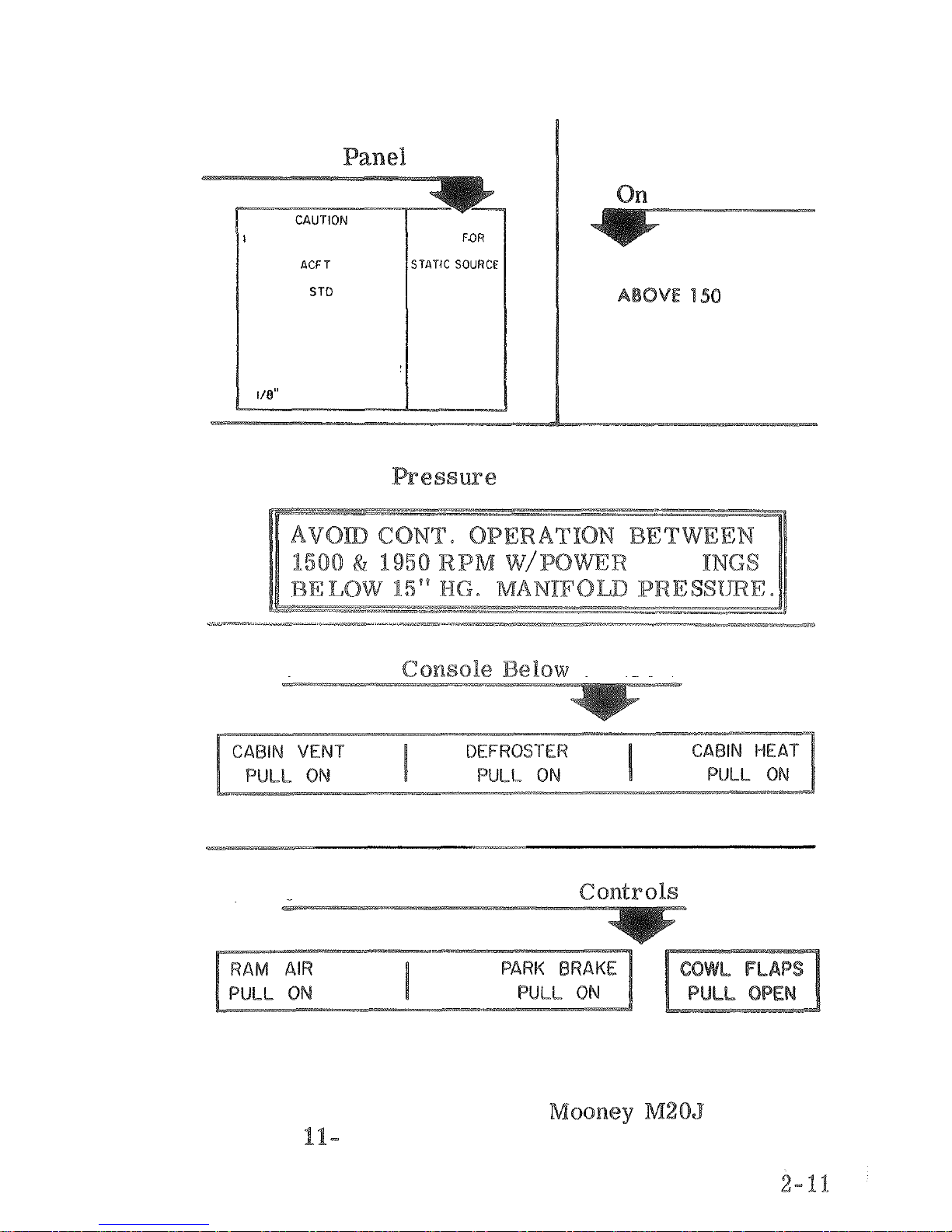
On
Lower
Left
Instrument
TURN OFF STROBE LTS
WHEN TAXIING NEAR
OTHER
OR WHEN
FLYING IN FOG OR IN
CLOUDS
LTS MUST BE USED FOR
ALL NIGHT OPERATIONS.
2
IN CASE OF FIRE TURN
OFF CABIN HEAT.
3
DO NOT SCREW VERNIER
CONTROLS CLOSER THAN
FROM NUT FACE.
PULL
ALTERNATE
Pilots Window
DO
NOT
OPEN
M.P.H.
On
Right
Instrument
Panel
Below
Manifold
Gage
SGTT
On
Lower
Controls
On
Lower
Console Below Controls
FAA
APPROVED
ISSUED
15-77
Airplane Flight
Manual
Page 32
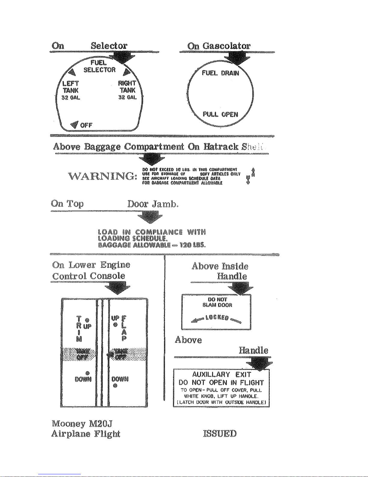
Fuel
Valve
Baggage
MAXIMUM
Door
Inside
Baggage
Door
.
.
FAA
APPROVED
Manual
11-15-97
Page 33
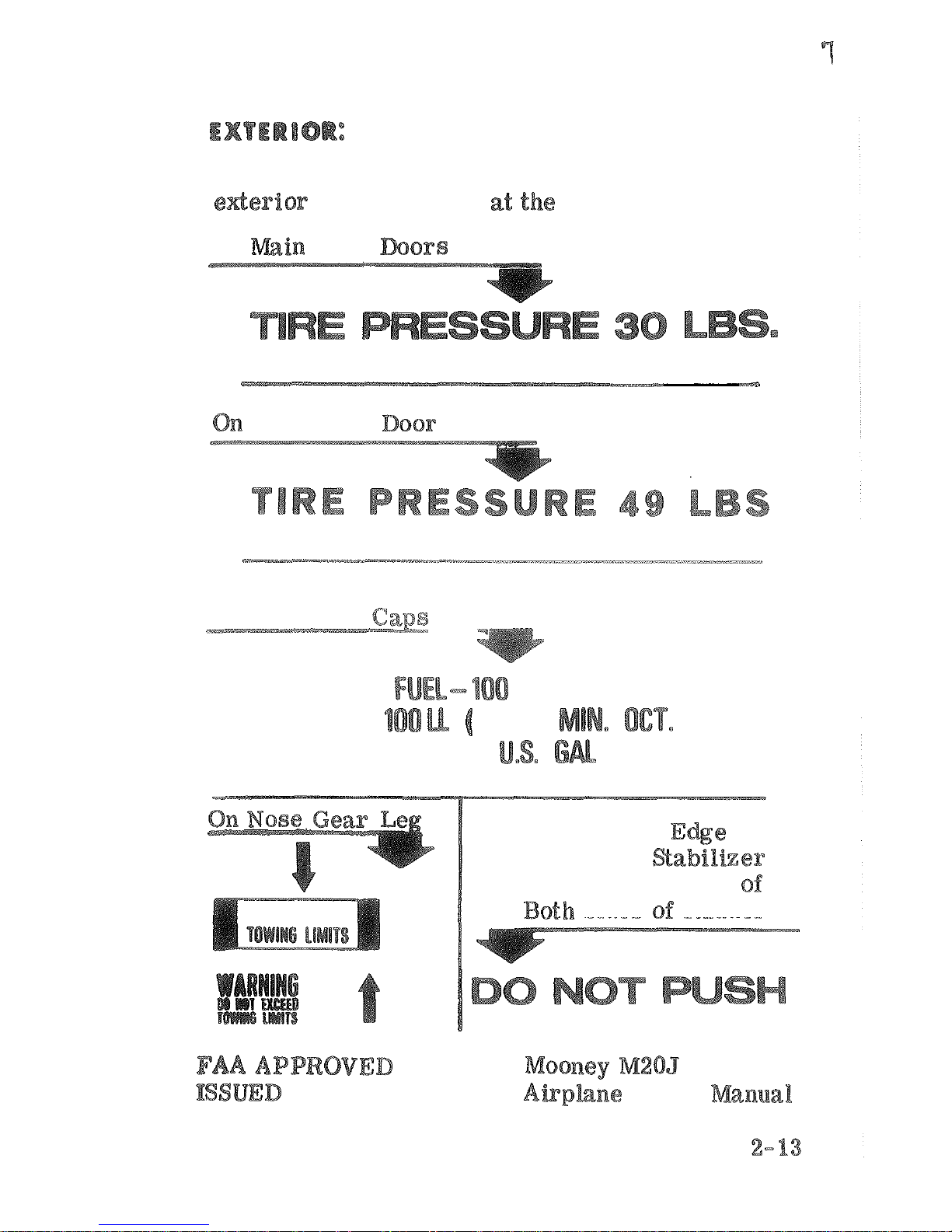
The
following
placards
must
be
installed
on
the
of
the
aircraft
locations
specified,
On
Gear
Nose
Gear
On
Fuel
Tank
,
---.-
(GREEN)
OR
BLUE)
3%
On
Leading
of
Horizontal
and
Trailing
Edge
Sides
Rudder
11-15-77
Plight
Page 34
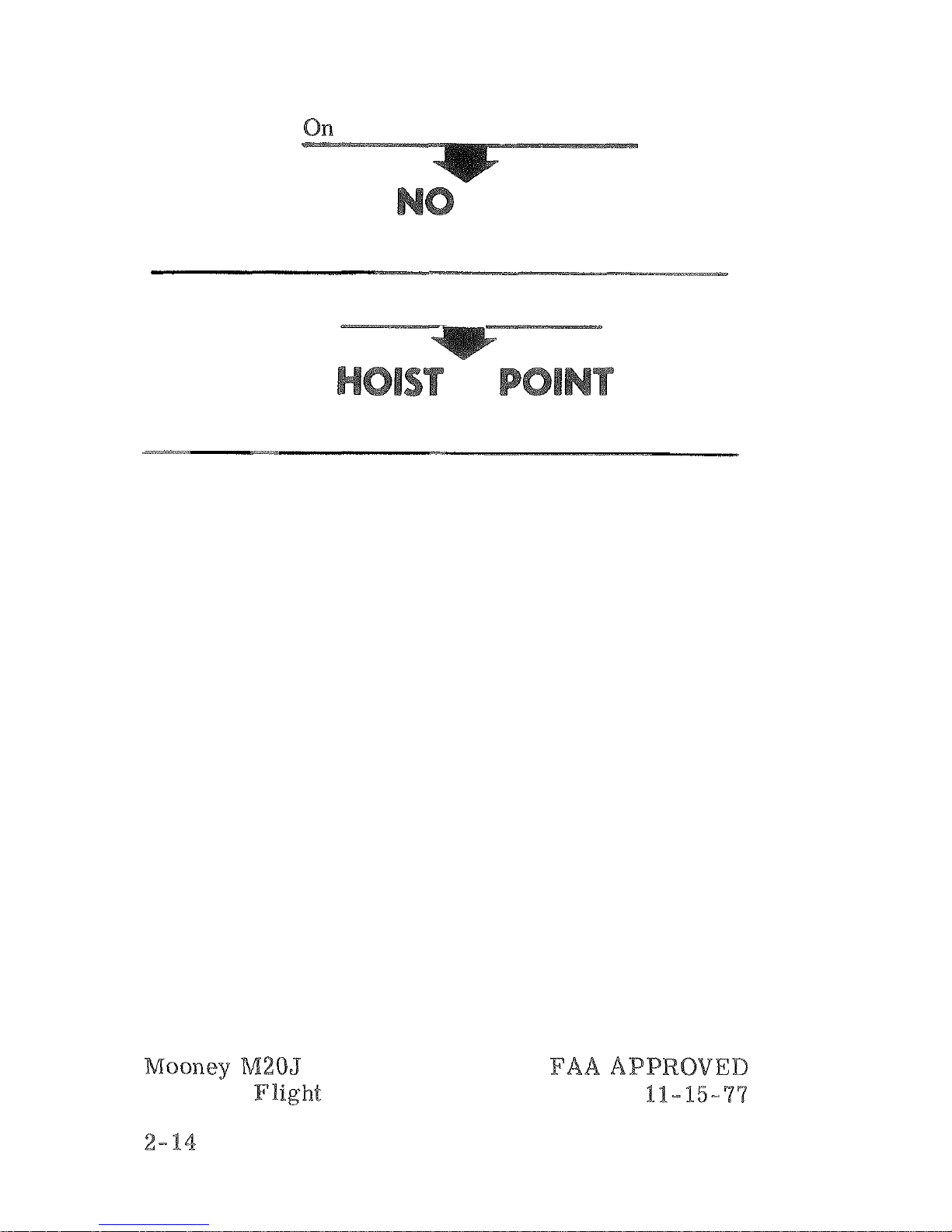
Inboard
End
of
Right
Flap
STEP
On
Underside
of
Wing
Airplane
Manual
ISSUED
Page 35
Page 36
This section provides the recommended procedures to
follow during adverse flight conditions. The
-
a
definite plan of action for coping with the most probable
emergency situations which could occur in the operation
As
it
is
not possible to have a procedure for all types of
emergencies that may occur,
is
the pilot's resgonsi-
knowledge of
of action. Therefore, It is considered mandatory that
the pilot
before
When applicable, emergency procedures associated with
optional equipment
in
Section
indicated
and
zero
instrument
error
Page 37
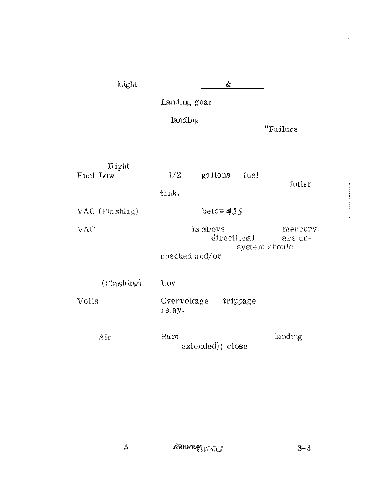
ANNUNCIATOR
PANEL
WARNING
LIGHTS
Warning
Fault
Remedy
Gear Unsafe
is
not in fully extended/
retracted position. Refer to
"
Failure
of
"
procedure
on
page
3-8
or "Fail~are
of landing gear to retract after take
-
off" procedure on page
3
-
%%.
Left or Right
2
to
3
the respective tanks.
Switch lo
Suction
is
(Steady)
Suction
5.5
inches of mesceary.
Attitude and dfrectioa~l gyros
reliable,
Vacuum
be
as
soon as
practicable.
Volts
"
Alternator Power
Loss
"
on page
3- 9.
Ram
air door
is
open (when landing
gear e%eended); close before landing.
REVISION
Page 38
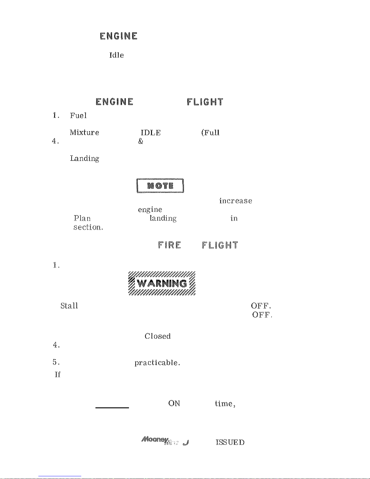
FIRE
-
GROUND
1.
Mixture
-
2.
Fuel Selector Valve Off
3.
Master Switch - Off
4.
Extinguish with Fire Extinguisher
FIRE
-
IN
-
OFF
2.
Throttle - C losed (Full Aft)
3.
-
Cabin Ventilation
Heating Controls - CLOSED
(Control Forward)
5.
-
DOWN OR
UP,
depending on terrain.
6.
Wing Flaps - EXTEND.
As
Necessary.
If
fire is not extinguished, attempt to iaacseaae
airflow over the engine
by
increasing
glide?
speed.
a power off landing as described
this
Do
not attempt
an
engine restart.
ELECTRICAL
IN
(Smoke in Cabin)
Master Switch - OFF.
Gear warning is not available with master switch
2.
Cabin Ventilation - Open
3.
Heating Controls
-
Circuit Breakers - CHECK. To identify faulty
circuit if possible.
Land as soon
as
to identify and isolate the faulty circuit as follows:
1.
Master Switch - ON.
2.
Select essential. switches
one at
a
and
permit a short time to elapse before activating an
additional circuit.
3-4
11-15-77
Page 39
GROUND
ROLL
Braking
-
Fuel Selector
-
OFF.
Master and Magneto/%art Switch-OFF.
AFTER
LIFTOFF
AND
-
Select Other Tank.
2.
-
ON.
3.
-
RICH.
-
CHECK
ON
BOTH.
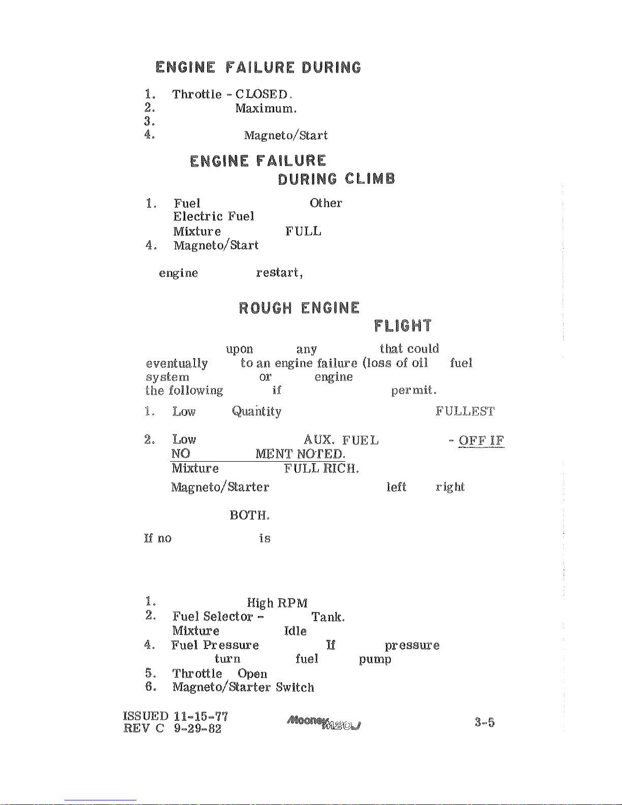
If
landing.
QR
LOSS
OF
POWER
IN
Immediately upon noting any condition
or
rough epxsgixae operation), perform
time
and altitude permit.
Fuel
-
FUEL
SELECTOR
TO
TANK.
Fuel Pressure
-
PUMP
ON
IMPROVE
3.
-
4.
-
Switch to left and right
single magneto operation; if no improvement,
switch to
noted, proceed to land as soon
as
practicable.
AIR
START
PROCEDURE
Propeller
-
(Full Forward).
Fuller Tank.
3.
Control
-
Cutoff (Full Aft).
-
Check.
no fuel pressme is
noted,
ON.
-
Both.
Page 40
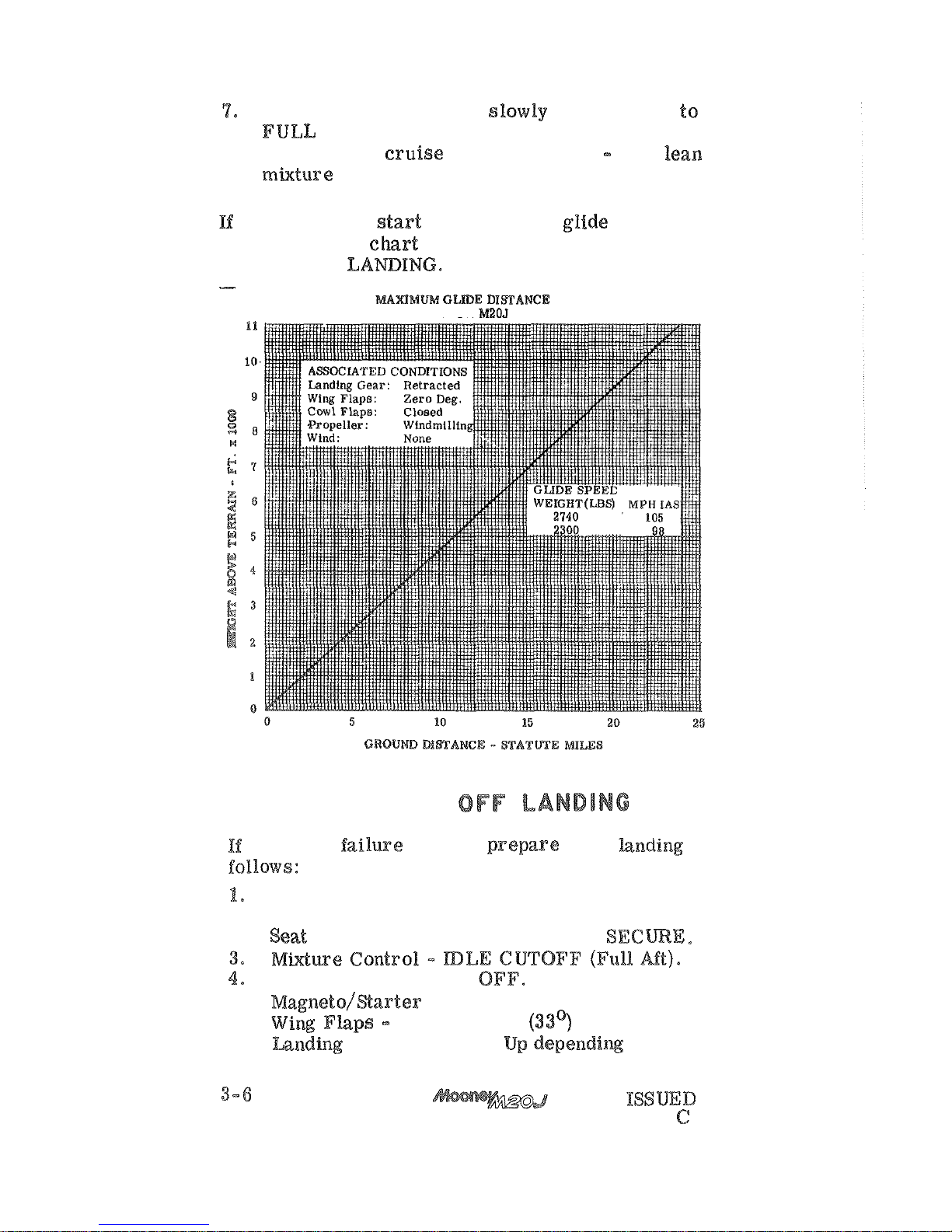
Mixture Control - Move slowly and smoothly
RICH (Forward).
8.
Re-establish cruise power and
RPM
then lean
engine fails to start establish best glide speed
indicated by the
POWER
OFF
MODEL
POWER
Emergency Locator Transmitter
-
ON
,
As
Required, (if installed)
2.
-
Fuel Selector Valve
-
5.
-
OFF.
6.
PULL
DOWN
7.
-
Down or
If-15-77
REV
9-29-82
Page 41
8%.
MPH
Master Switch
-
OFF,
Up
to
2000
feet
of
altitude may be lost in
one turn spin and
recovery; therefore, stalls at low altitude are extremely
The best spin recovery technique
is
to avoid flight conditions
spin
entry.
Low speed flight near stall should
be approached with caution and excessive flight control
in
this RligM regime should be avoided,
an
to progress into a deep stall. Fast, brat smooth stall recovery
spin, If an
unusual post
a
quick
application of anti-spin procedures should shorten the
ARE
In
the event of
an
be used:
Rudder
-
FULL
RUDDER
opposite the direction
of spin,
Control Wheel - FORWARD of neutral in
a
be
required
if
the rotation does not stop.
3.
-
4.
TO
Hold anti-spin co&roRs until rotation stops:
-
as
possible.
6.
Rudder
-
Control Wheel - Smoothly move
to bring the nose
up to
a
level flight attitude,
ISSUED
15-77
9-29-82
Page 42
OF
TO
EXTEND
Airspeed
2.
PULL
Gear Switch
-
4.
FORWARD,
LEVER
BACK.
Slowly u%l
1
to 2 inches (2.5 to
5.1
it
5.
-
to 20 inches) and
RETURN
gear 18 down and locked, GEAR
to 20 pulls).
6.
Down Indicator
-
Check
viewing from
activating
electrical
system.
Gear Adwtor
not operate kndiw gear electrically
GEAR-UP
a
normal
When
are
sure
of
Mixture
-
(Full
Aft).
3.
-
OFF.
4.
Fuel Selector Valve
OFF.
5.
Keep
level d~aring touchdown.
Page 43
UNLATCHED
IN
the cabin door
is
not locked it may come unlatched
flight. This may occur during or just after take-off.
The door will trail in a position approximately
3
inches
open, but the flight characteristics of the airplane will
not be affected.
Return to the field
in
a
normal manner.
-
out have a passen
-
ger hold the door to prevent it from swinging open.
If it is deemed impractical to
can be closed in flight, after reaching a safe altitude,
by
the fo%%owing procedures:
Slowtoapproximately 1%0mph/96Mse
2.
Open the storm window to redrace cabin air pressure.
3.
4.
in
a right slip) and close the door,
LOSS
red
steadily,
the
radio
switch
off
and
oaa
to reset the voltage regralator. If the voltage
light comes on again
equipment not essential for
flight should be turned off and the flight terminated as
soon as practical to correct malfunction.
A
flashing
voltage
-
resetting the alternator field breaker does not restore the
alternator, turn off
as
soon as practical,
tripped main alternator circuit breaker can
only be caused
by
a
shorted alternator circuit
breaker. This should be verified by
Page 44
ing to reset the breaker not more than one time.
If this fails, pull the alternator field breaker,
turn off all non
-
essential electrical equipment
and terminate
OPERATE
icing conditions are inadvertently encountered:
Turn
Do not turn ram air on again
when
air
until assured all ice and
snow
melted from tlae aircraft.
2.
Shut cabin heat off until. engine operation
is
normal.
3.
Push
(if
installed).
4.
air
source to
ALTERNATE
(if
installed).
Turn back or change altitude to obtain an outside
air
temperature less conducive to icing.
ALTERNATE
SOURCE
The
alternate static air source should
it
is
suspected that: the raoranal. static air sources are blocked.
Selecting
the
alternate position changes the source of static
air for the altimeter, airspeed indicator and
from the outside of the aircraft to the cabin interior.
air
source
is
use adjust the
indicated airspeed and altimeter readings according to the
appropriate alternate static source airspeed and altimeter
calibration tables in Section
5.
he static air source valve is located in the lower left
portion of the pilot's flight
left
knee.
Page 45
FAILURE
OF
GEAR
TO
RETRACT
AFTER
TAKEOFF
The following procedure applies to all
aircraft modified with the airspeed
safety override system with the
PASS
"
switch
24-0238
and above)
and
aircraft prior with the mechani
-
retraction
"
BY
PASS
"
switch in accor
-
In the event that the gear fails to retract when the landing
gear control switch
is
placed
in
the
"UP"
position due to
the failure of the airspeed sensing or squat safety
lo activate after takeoff, the followtlag procedure should
be
as
an alternate means to
retraction:
fails
lo
actuate,
as
evidenced
by
sf
the
BY BASS
"
the
activation
the gear warning &zorn, depress
SAFETY
BY
PASS" switch and hold until gear is
This is evidenced
by
both the
gear unsafe and
gear
down
"
(2)
"
GEAR
circuit breaker to shut off gear
horn.
of the horn, but must be reset prior to
ex
-
tension of the landing gear).
(3)
"
GEAR
circuit
breaker
the
position.
Check "AESPEED" or
safety switch to
determine
11-15-'77
3
-
Page 46

Page 47
TIT
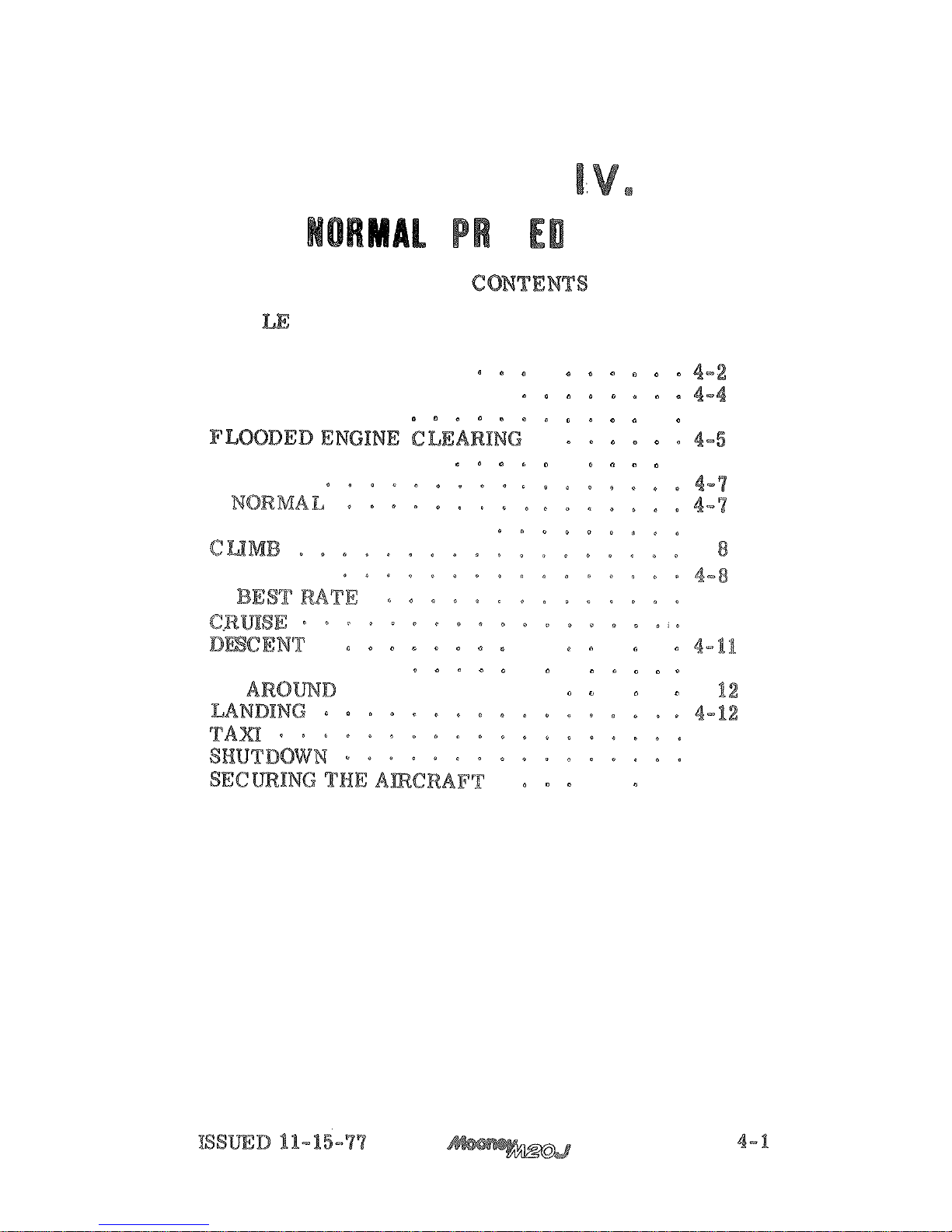
SECTION
TABLE
OF
PAGE
PREFLIGHT
INSPECTION
. a
BEFORE
STARTING
CHECK
STARTING
ENGINE
.
4-4
BEFORE
TAKEOFF
.
.
.
4-5
TAKEOFF
OBSTACLE
CLEARANCE
4-8
4
-
NORMAL
4-9
4-10
.
.
.
.
.
BEFORE
LANDING
.
.
4-11
GO
(BALKED
LANDING)
.
4
-
4-12
4-13
.
.
.
.
4-13
Page 48
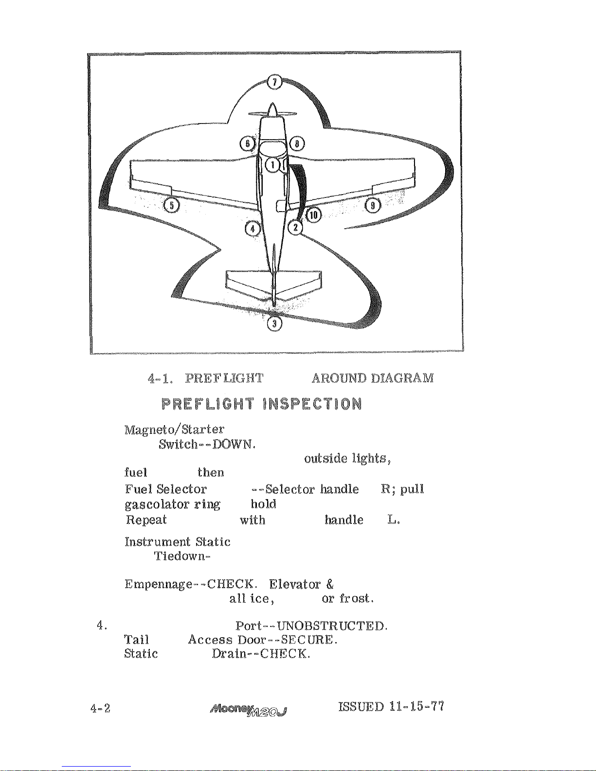
FIGURE
WALK
a.
Switch,--
OFF.
Gear Switch--NWN.
Master Switch--ON to
check
OFF.
and hold far
five
seconds,
on
2.
-- UNOBSTRUCTED.
Tail
-
REMOVE.
3.
rudder attach
points. Remove
snow, or frost.
Instrument Static Port--mOBSTR%TCTED.
Page 49
5.
Wing Skins--
CHECK.
Flap and Attach Points
--
CHECK.
Aileron and Attach Points
--CHECK
.
Wing Tip Strobe and Navigation Light--CHECK.
Remove all ice, snow, or frost.
Wing
--
CHECK.
Fuel Tank--
CHECK QUANTITY:
reduced fuel indicator
is
neck. This indicator
is
used to indicate use-
able fuel capacity of
25
S. gallons,
Chock
--
REMOVE.
--CHECK,
--
CHECK.
Tank
--CLOSED.
LEAN.
Fasteners
-
for
Forward Engine Components--@BIEGK starter,
alternator
Door--CHECK
and
secure.
Landing Light
--
@HECK.
Nose Gear
--CHECK tire; cheek for towing damage.
--
CHECK.
Chocks
--REMOVE.
8.
Right Side Engine Cowl Fasteners--SECURE.
Engine
--
CHECK (Full for edended
flight).
Fuel
Drain--
SAMPLE.
Tank Vent
- - UNOBSTRUCTED.
-
REMOVE.
Main Gear, Shock Discs and Tire--
CHECK.
Right
--CHECK.
4-3
Page 50
15.
Fuel. Tank--CHECK QUANTITY.
A
reduced fuel indicator is located in the filler
neck.
This
indicator
is
used to indicate useable
capacity of
25
gallons.
-
CHECK.
Wing Tip Strobe (if
Light
-
CHECK,
Aileron and Attach Points
-
CHECK.
Flap and Attach Points
-
CHECK.
Remove all ice, snow, or frost.
Baggage Door
-
SECURE,
BEFORE
Preflight Inspection - COMPLETE,
Emergency Locator Transmitter
-
Seats, Seat Belts and Shoulder Harness
(if
-
ADJUST AND SECURE,
Fuel Selector Handle
-
SET for fuller tank,
DEPRESS BRAKE PEDALS
PULL
ON.
and
Master
Switches .-
OFF,
Radio Waster
Switch
OFF.
Cowl Flaps
OPEN (Control FULL
Aft),
Ram Air Control
CLOSED,
Landing Gear
Switch - DOWN.
Mixture Control
-
IDLE
CUTOFF,
Propeller
FORWARD HIGH
Throttle - CLOSE (Full Aft),
Electric Fuel Boost Pump
-
OFF,
All External Lights - OFF,
Cabin Heat
-
OFF.
-
CHECK.
Alternate Static Air Control
-
CHECK IN,
ENGINE
When
external power source
Adapter is available from Mooney Aircraft
Corporation) no special starting procedure
is necessary, Use normal starting procedures
be low,
REV
3-7-84
11-15-77
Page 51
PO.
Propeller Control
Throttle Control
-
FORWARD l/4,
Master Switch - ON.
Mixture Control
-
Electric Fuel Boost
Pump
Switch - ON TO ESTABLISH
PRESSURE, THEN OFF.
Mixture Control
-
FULL
AFT
(IDLE CUT
-
OFF) .
Propeller Area - CLEAR.
-
TURN
AND
PUSH TO START,
RELEASE TO BOTH WHEN ENGINE STARTS.
Mixture
-
MOVE SLOWLY AND SMOOTHLY TO RICH.
Oil Pressure Gage
-
If minimum oil pressure not
indicated within
30
seconds, STOP ENGINE, and
determine trouble,
Cranking should
be
limited to
30
seconds,
and
several minutes allowed between crank-
ing periods to permit the starter to
Throttle
Set for LOO0 to 1200
CLEARING
OPEN
FORWARD),
--IDLE
(FULL
Electric Fuel Boost Pump--OFF1,
--turn to "START'hnd
PUSH forward.
Throttle
-
when engine starts.
-
(FULL FORWARD).
Oil Pressure
not indicated within
30
seconds, STOP ENGINE,
and determine trouble.
BEFORE
TAKEOFF
Parking Brake--
SET.
Controls
--
@HECK
FREE
CORRECT
MOVEMENT.
Radio Master
--
ON
Instruments and Radios
-
-
CHECK
AND
DESIRED.
REV
3-7-84
ISSUED
11-15-77
Page 52
5.
Strobe Lights and Rotating Beacon--
OW
(if
installed).
Annunciator Lights
-
-
CHECK WITH PRESS-TO
-
TEST
THROTTLE RETARDED.
Trim
--
TAKEOFF SETTING.
If
forward
CG
set
trim to upper portion of band and to
when at aft
CG.
THROTTLE
--
Magnetos
-
-
CHECK. Make magneto check at
1900
-
2000 RPM, as follows:
a.
BOTH to
-
Allow time
for plugs to clear.
-
Note
-
BOTH.
The
drop
should not
WPM
on either magneto
or
indicate greater than a 50
differen
-
tial between magnetos.
An absence of
RPM drop
be
indication of faulty magneto ground
-
ing
If
there
is
doubt concerning Ignition system
operation,
speed will usually confirm
a deficiency exists.
Propeller Control
-
Throttle
IDLE RPM.
Cabin Boor
-
LOCK.
Seat Belts
-
SECURE.
TAKEOFF
ISSUED
Page 53
TAKEOFF
Move the codrolls slowly and smooth$y. In
particular, avoid rapid opening
the
as
the engine
is
counterweighted
is
a
of
Roper full throttle ewine operatibn should
be checked early in the takeoff roll. Any
significant indication of rough or sluggish
engine response
is
reason ta discontinue the
takeoff.
When takeoff must
be
made over a gravel
is
important that the throttle
be
applied s%ow%y. This
the
to start
before
a
high
RPM
is
sped,
and
gravel
or
be
from tlae
instead
into
Boost
-
QN
at
start
of
takeoff roll,
Power
FUEL
and
-
WFT
NOSE
AT
MPH
(62
-
MPN
(71
5.
-
RETRACT
IN
CLIMB
BEFORE
ATTAINING AN AIRSPEED
OF
(104
Wing
-
RETRACT
IN
CLIMB.
7.
Boost Pump
-
CHECK
PRESSURE.
Page 54
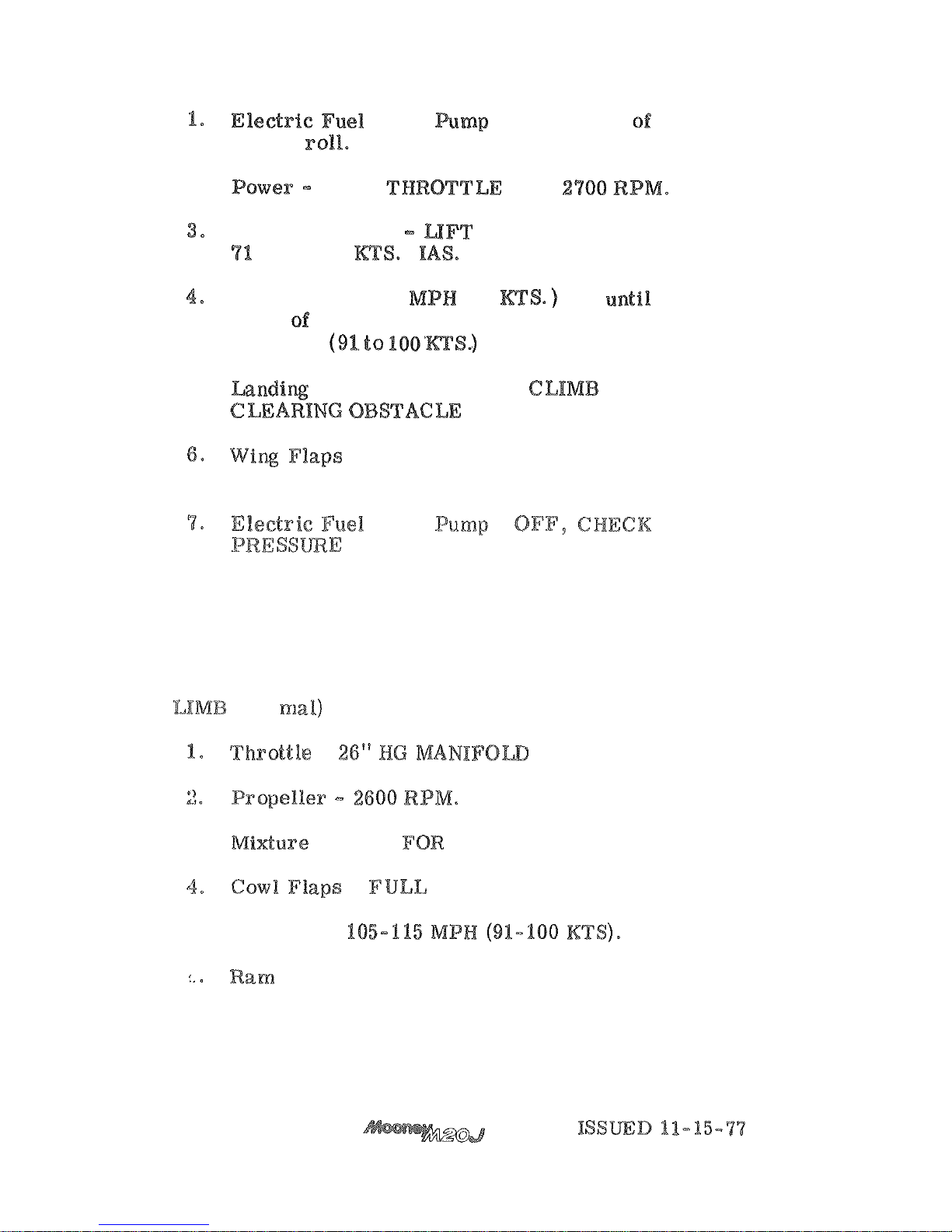
TAKEOFF
(Obstacle Clearance)
-
ON
at start
takeoff
2.
FULL
AND
Aircraft
Attitude
NOSE
WHEEL
AT
MPH
(62
)
Climb
Speed
-
76
(66
IAS
clear
obstacle, then accelerate
to
105
to
115
MPH
IAS.
5.
Gear
-
RETRACT
IN
AFTER
.
-
RETRACT
AFTER
CLEARING
OBSTACLE.
Boost
-
,
CLIMB
(Nor
-
PRESSURE.
3
-
LEAN
SMOOTH
OPERATION.
-
OPEN.
5.
Airspeed
-
Air
-
OPEN
AFTER
ENTERING
CLEAR
AIR.
Page 55
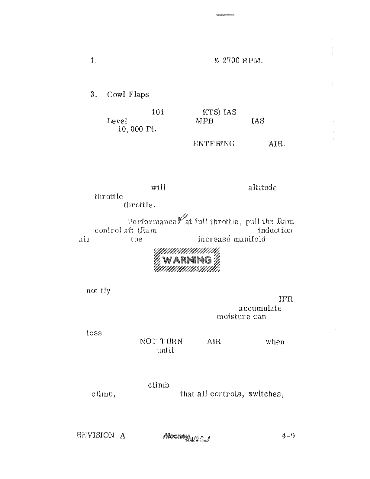
CLIMB
(Best Rate)
Power - FULL THROTTLE
2.
Mixture - LEAN FOR SMOOTH OPERATION.
-
FUEL
OPEN.
4.
Airspeed
-
MPM
(88
at Sea
94
(82
KTS) IAS
at %0,000 Ft.
5.
Ram Air
-
ON
AFTER
Manifold pressure
drop with increasing altitude at
any
be
restored by gradually
opening the
To
Increase ~ex?ormance<ak ftuli throttle,
Air
Air
ON position) allowing inducll.on
to
bypass the
air
filter
and
Turn ram air off
if
encountering icing conditions.
Do
filtered induction air when flying in snow or other
conditions can be hazardous.
Snow can
in
the fuel injector impact tubes, or moisture can freeze
in the inlet passages under icing conditions to cause
-
countered
DO
RAM
ON AGAIN when
entering clear air until assured that all ice has melted
from the aircraft. Do not use ram air in visibly dusty
air.
After establishing
for
instruments are set and functioning properly.
Page 56
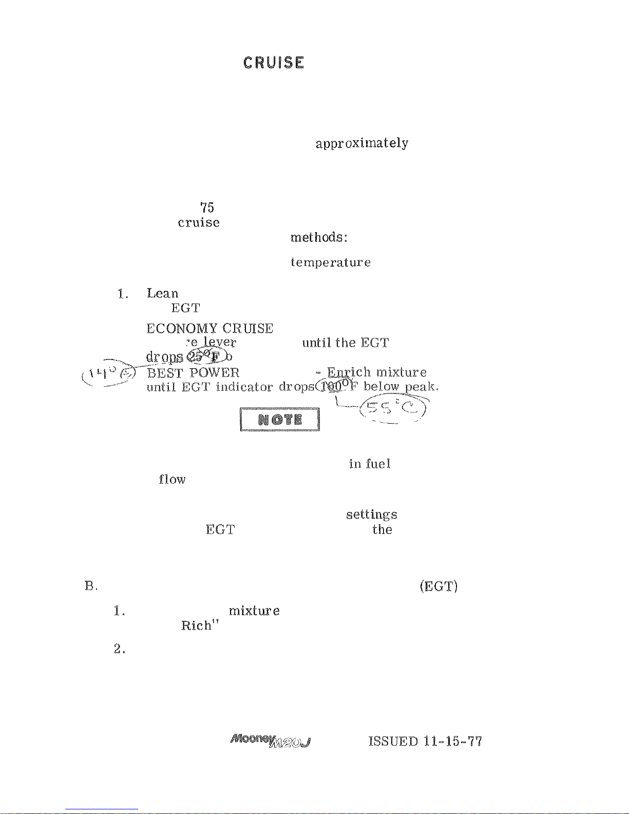
Upon reaching cruise altitude, allow acceleration to
cruise airspeed, then trim the aircraft for level flight,
reduce manifold pressure and
RPM
to desired cruise
power, and close the cowl flaps. The cowl flaps should be
partially opened (control pulled aft
inches)
if
necessary, to maintain the oil and cylinder
head temperatures within the normal operating range.
When cruising at
percent power or less, lean the
mixture
after
is
established in accor
-
dance with one of the following methods:
A.
Leaning using exhaust gas temperature gage (EGT)
(if installed)
the
indicator.
-
Enrich mixture (push
mixture
indicator
r
more below peak.
M
I
X
TUR
E
Best power mixture will result in a
speed increase, an increase
a
reduction in range.
2.
Changes in altitude and power settings require
the
peak
to be rechecked and the mixture
re
-
set.
Leaning without exhaust gas temperature gage
Slowly move mixture control lever aft from
"
Full Richqs position toward lean position.
Continue leaning until slight lass of power
is
noted (loss of power
may
or may not be accom
-
panied by roughness).
Page 57
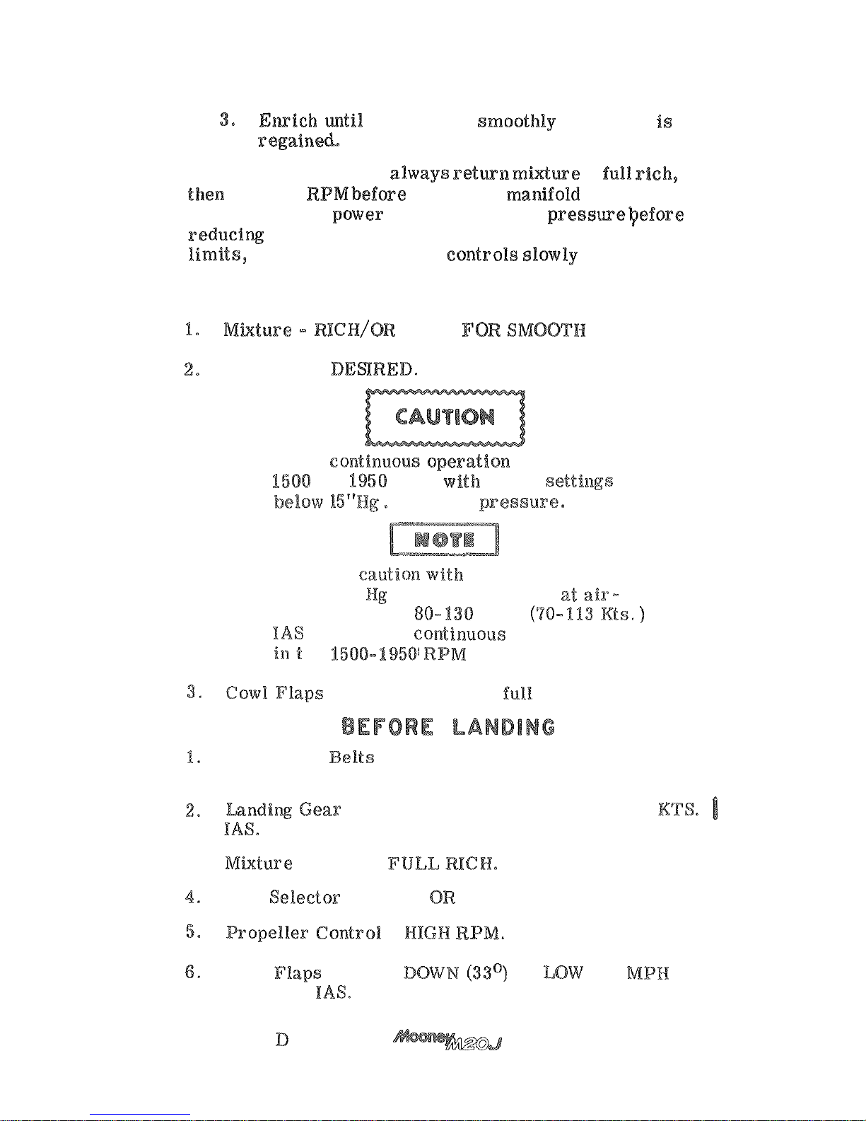
When increasing power always return midwe to full rich,
when decreasing
RPM.
Always stay
within
the established operating
DESCENT
LEAN
OPERATION.
Power
-
AS
Avoid
and
RPM
manifold preseaare,
Exercise caution with
power
settings
below
15
"
manifold pressure at air
MPB
to preclude continuous operation
be 1508-1950'RPM restricted range.
-
CLOSED
(control
forward),
Seats, Seat Belts and Shoulder Harnesses - ADJUST
AND SECURE,
-
EXTEND
BELOW
155
MPN
(135
)
3.
-
Fuel
-
RIGHT
LEFT (Fullest
tank),
-
Wing
-
FULL
BE
132
(115
KTS)
REVISION
4-11
Page 58
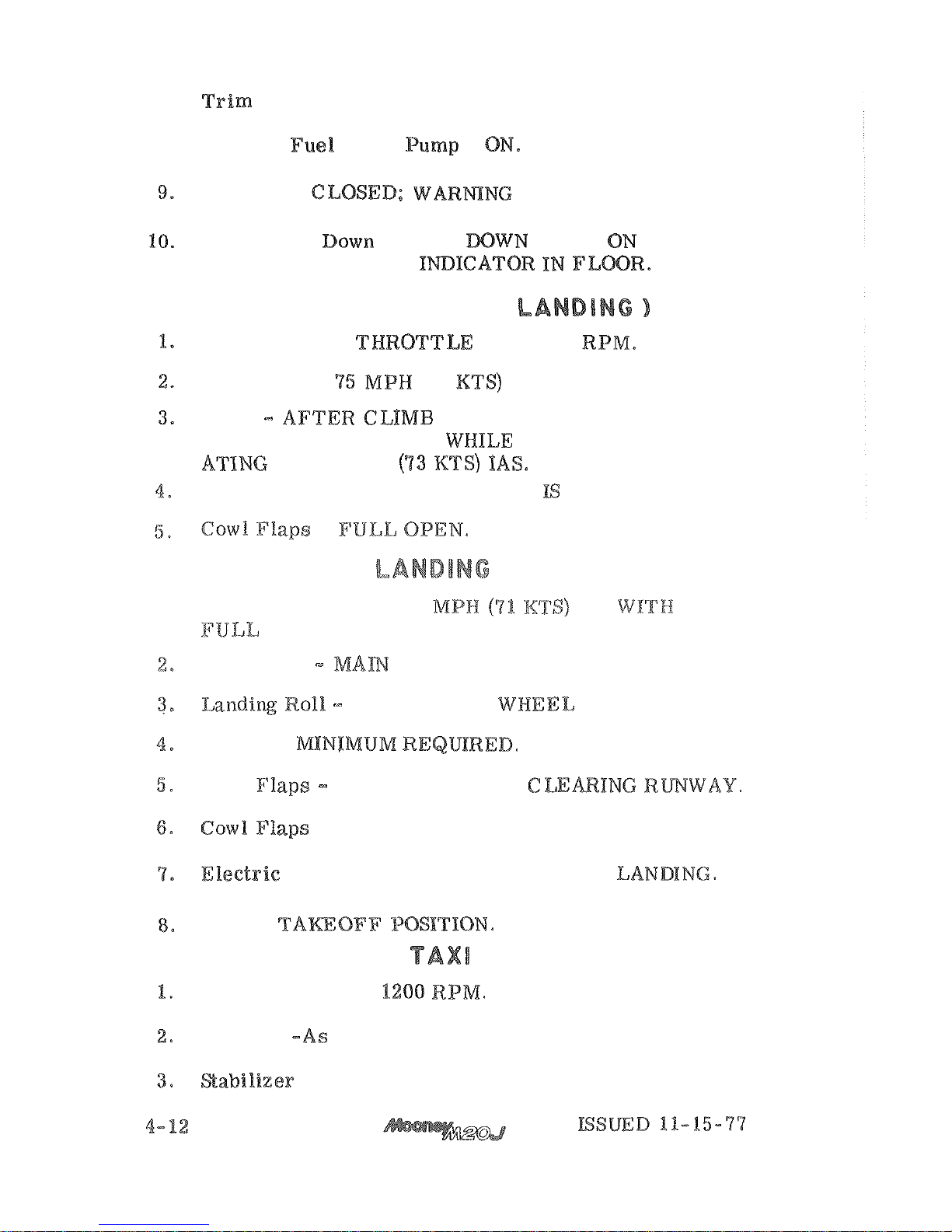
7.
-
ADJUST,
as necessary,
8.
Electric Fuel Boost
-
Ram
Air
-
LIGHT
OFF.
Check
Gear
-
GEAR
-
MARKS
ALIGNED IN VISUAL ImIGATOR
GO
AROUND
(BALKED
Power
-
FULL
AND
2700
AIRSPEED
-
(65
IAS.
Flaps
ESTABLISHED RE
-
TRACT
TO 0 DEGREES WHILE
ACCELER
-
TO
84
MPM
Gear - RETRACT
AFTER
CLIMB
ESTABLISHED,
-
Airspeed
on,
Final
-
8%
IAS
FLAPS,
Touchdown
WHEELS
FIRST.
LOWER
NOSE
GENTLY.
Brakes
-
Wing
RETRACT
AFTER
-
OPEN
Pump
-
OFF
AFTER
Trim
-
Throttle--1000
to
Lighting
-
required.
Trim- -
TAKEOFF.
Page 59
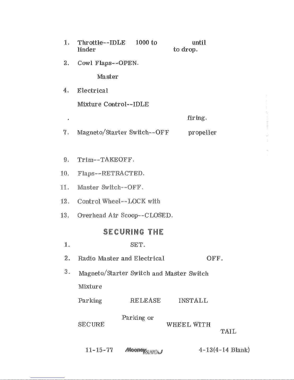
SHUTDOWN
1200
RPM
cy
-
head
temperature starts to
3.
Radio
Switch--
OFF.
--OFF.
5.
CUTOFF.
6
Throttle--RETAR%)
as
engine stops
when
8.
Parking Brake--
Set (for short-term parking).
seat
belt.
AIRCRAFT
Parking Brake
-
-
-
OFF.
4.
Control - IDLE CUTOFF,
5.
-
AND
WHEEL,
CHOCKS.
6.
For
Extended
in
Gusty Wind Conditions
-
SEAT
BELT,
TIE
DOWN AIRCRAFT
AT
WING AND
POINTS.
ISSUED
Page 60

Page 61
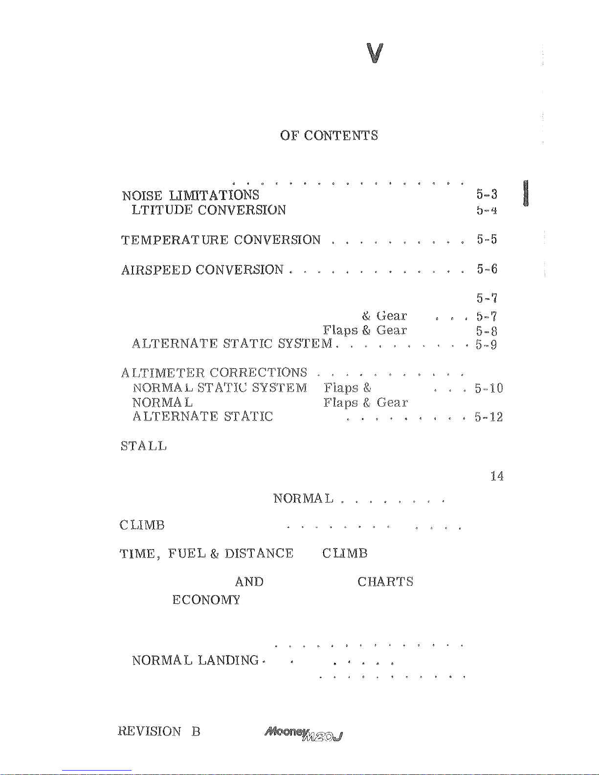
SECTION
.
PERFORMANCE
TABLE
INTRODUCTION
5-3
.................
.............
A
............
AIRSPEEDCALIBRATION 5-7
NORMAL
STATIC
SYSTEM . Flaps
Up
NORMAL
STATIC
SYSTEM
.
Down
.
.
.
Gear
Up
STATIC
SYSTEM
.
Down
.
.
5-11
S
Y
S
TEM
.................
5-13
TAKEOFF
DISTANCES
MAXIMUM PERFORMANCE
.
5
-
TAKEOFF DISTANCES
5-15
PERFORMANCE
5-18
........
5-17
....
CRUISE.
RANGE
ENDURANCE
5-19
................
BEST ECONOMY
5-20
.................
BEST POWER
5-28
LANDING DISTANCES
5-30
....
.
.
5-36
MAXIMUM PERFORMANCE
5-37
5- 1/5-22
BLANK
Page 62

Page 63
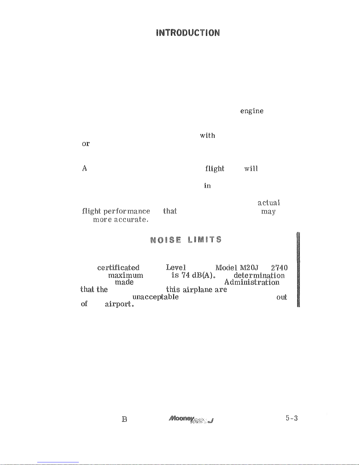
All
performance tables and graphs are grouped In this
section of the manual for quick and easy reference. The
information is presented to show performance that may
be expected from the aircraft, and to assist you in
planning your flights with reasonable detail, and accur
-
acy. All data has been compiled from both calculations
and actual test flights with the aircraft and
good operating condition while using average piloting
techniques. The cruise performance data makes no
allowance for variables present
allowances must be made for actual conditions.
carefully detailed and analyzed flight plan will yield
maximum efficiency. After making a flight plan based
on estimates taken from the data
this section, you
should check your actual performance and note the
difference between your forecast conditions
and
your future estimates
be
The
at
pounds maimurn weight
No determim-tion
has been made
by
the Federal Aviation Administratioaa
be
acceptable or uceeptable for operation at, into, or od
any airpod,
REVISION
Page 64
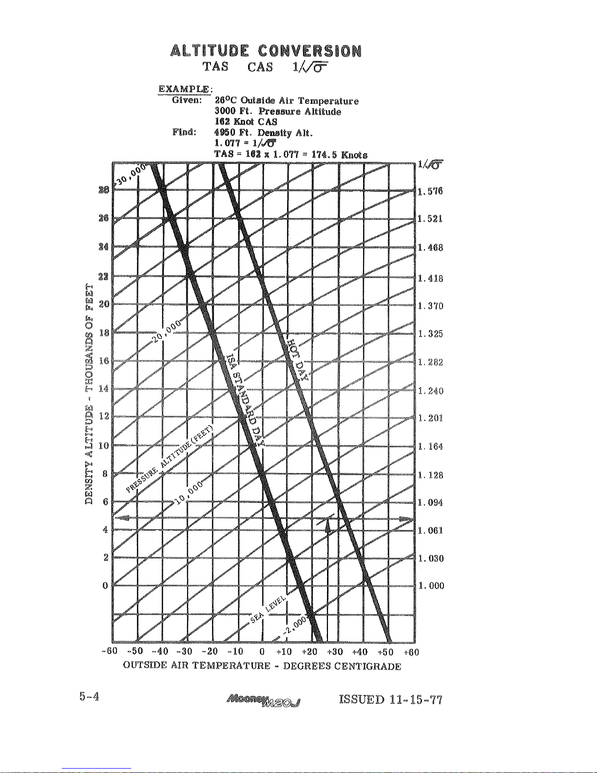
=
x
Page 65
Page 66
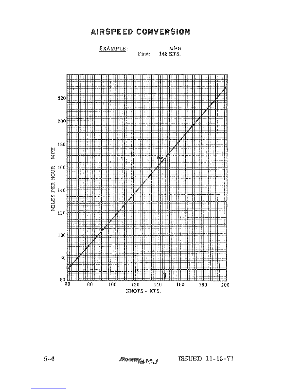
Given:
168
Page 67
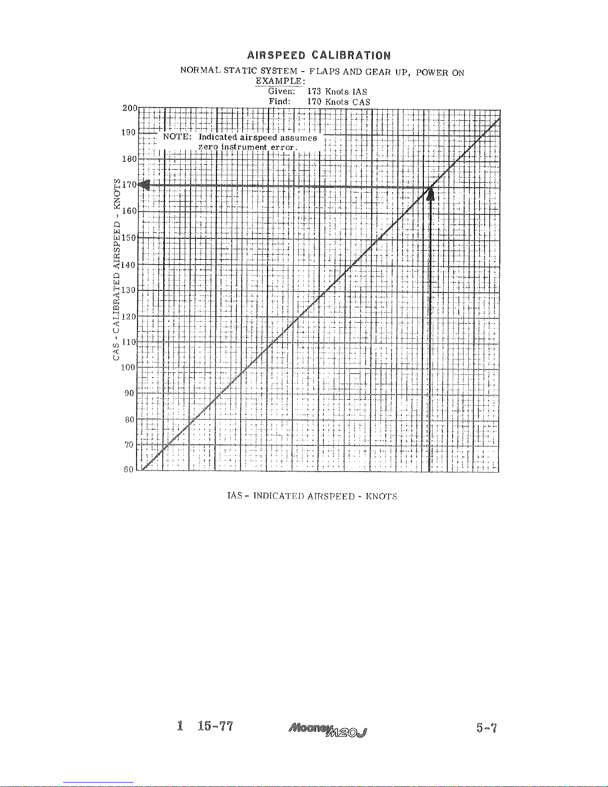
60 70 80 90 100 110 120 i30 140 150 160 170 180 190 200
ISSUED
1
-
Page 68
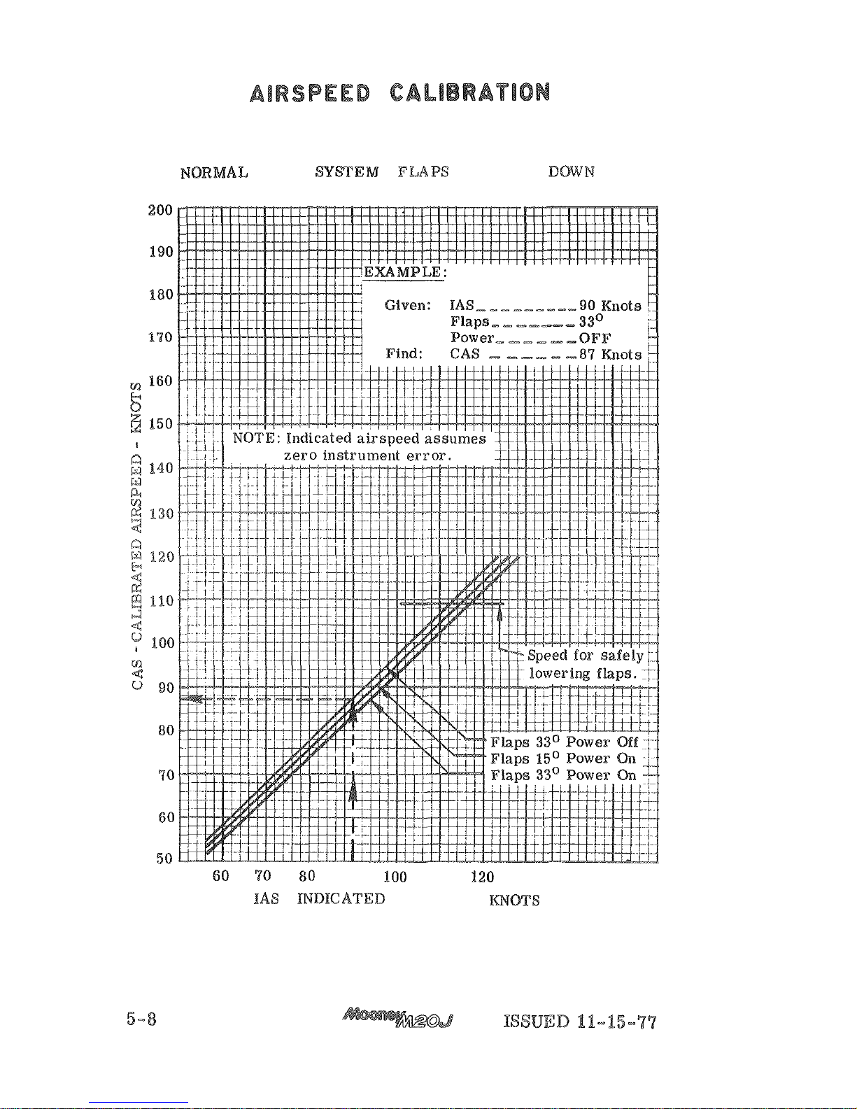
-
AND
GEAR
50
-
AIRSPEED
-
Page 69
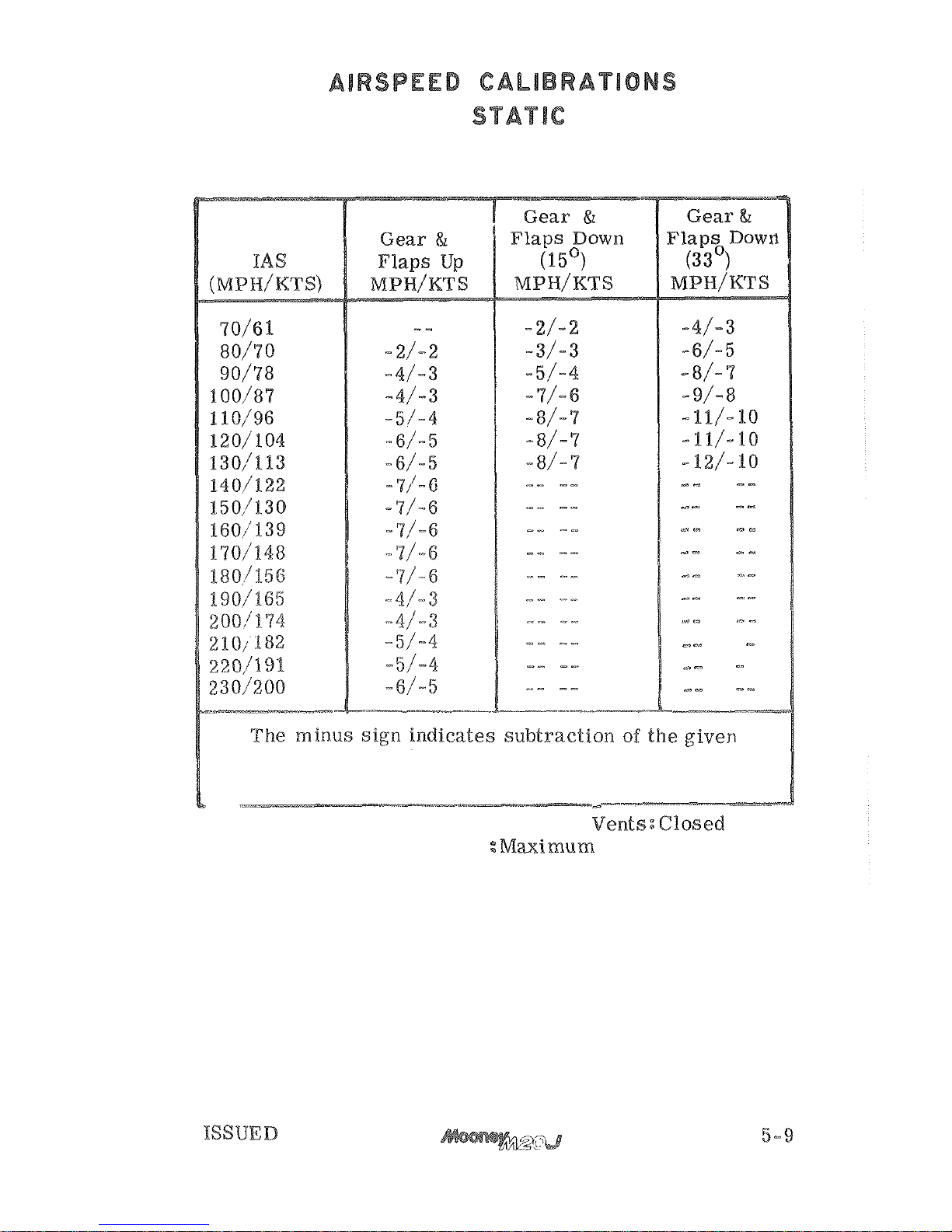
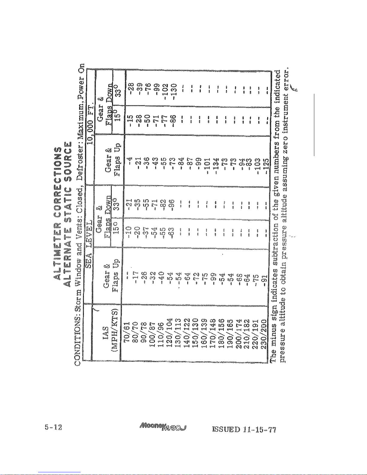
ALTERNATE
SOURCE
-
-
numbers from
IAS
to obtain
@AS
assuming zero
instrument error.
CONDITIONS:
Storm
Window and Vents:@Iosed
Defroster
Power On
11-15-77
Page 70
Page 71
ISSUED
Page 72
Page 73
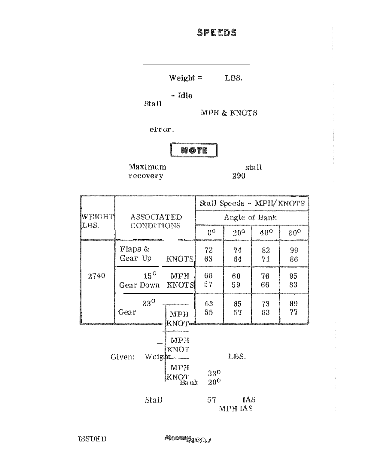
STALL
ASSOCIATED
CONDITIONS:
Gross
2740
Forward
CG
Power
airspeeds in
and assume zero instrument
during
is
approximately
feet
Flaps
Flaps
EXAMPLE:
2740
Landing Gear Down
Flaps
Angle
of
Find:
Knots
65
11-15-77
5-43
Page 74
Page 75
ISSUED 11-15-
77
Page 76
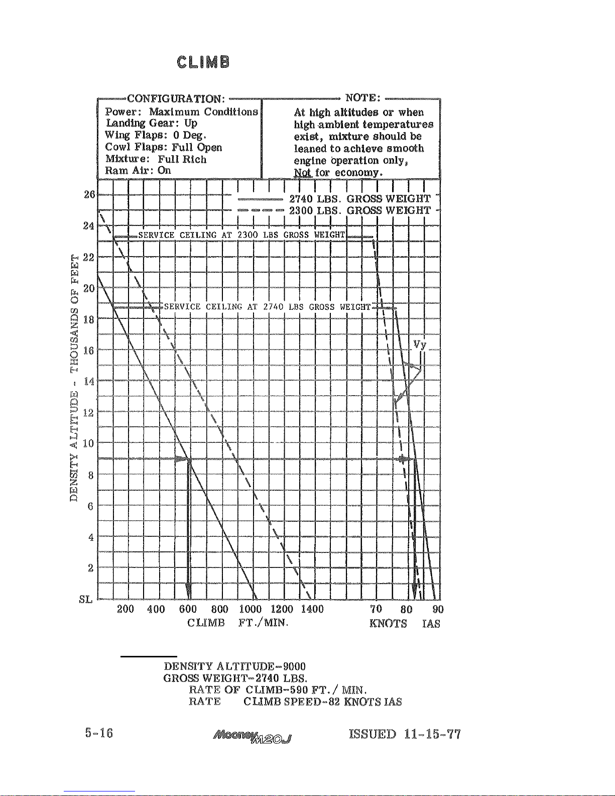
PERFORMANCE
RATE
OF
-
-
EXAMPLE
GIVEN:
FEET
FMD:
BEST
BEST RATE
OF
Page 77
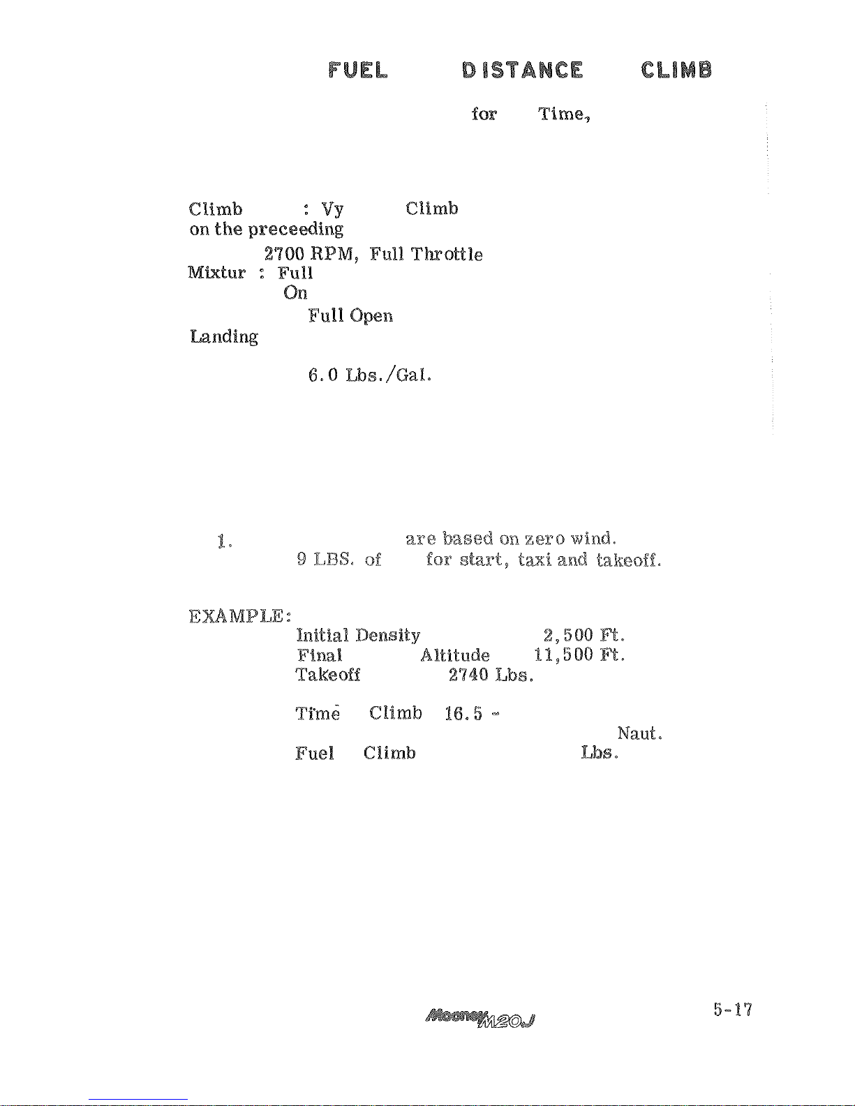
TIME,
AND DlSTANCE
TO
Associated Conditions for
the
Fuel
and
Distance to Climb graph
on
the following page:
Speed
Performance graph
page.
Power:
Rich
Ram
Air:
Cowl Flaps:
Gear:
Up
Wing Flaps: Up
Fuel Density
NOTE:
Distances
shown
2.
Add
fuel
Given:
Weight
-
Find:
to
(
3.
Q)
13.5
Minutes
Distance to Climb
(23.
5
-
4.5)
19.
Q
Mi.
to
(24.5
-
5.0)
19.5
ISSUED
11-15-77
Page 78
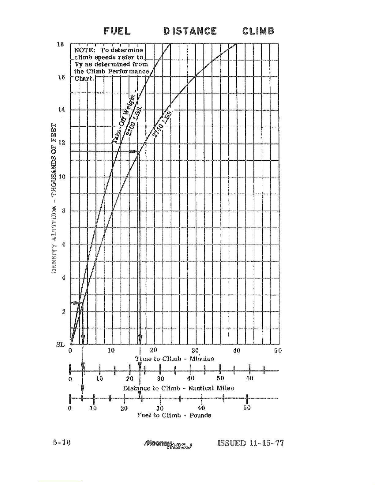
TIME,
AND
TO
Page 79
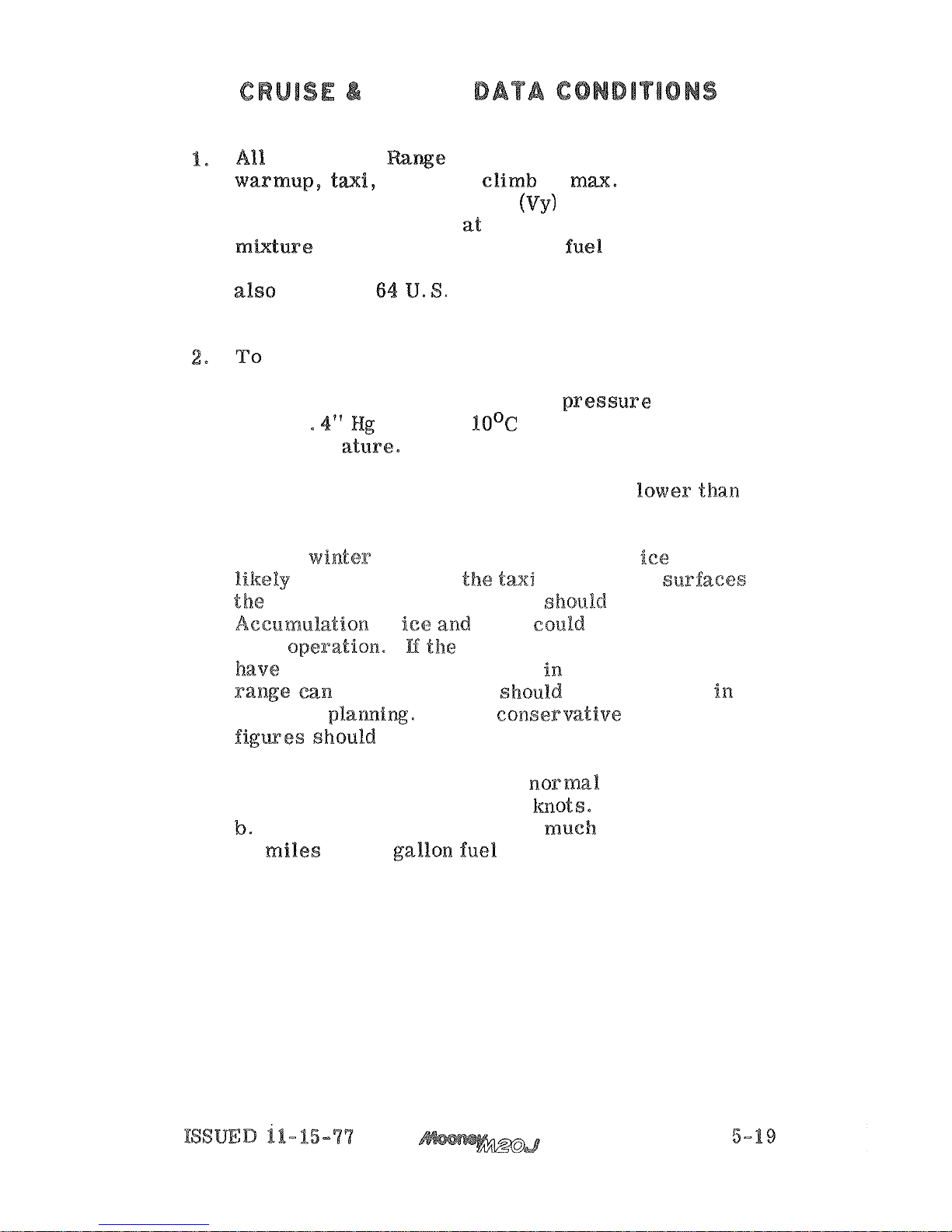
RANGE
Cruise and -we Data tables allow for:
-
off, climb at ma. power at
the best rate of climb speed
a
cruise to destination at the specified power and
-
minute fuel reserve
at
the same altitude and power setting. The data
is
gallons of usable fuel,
standard atmosphere, and no wind.
and Range Data tables on non
-
standard days, in
-
crease or decrease the manifold presstare approxi
-
mately
for each 1Io0C variation in outside,
air
temper attare. Increase manifold pressure for
air
temperatures above standard and decrease
manifold pressure for air temperatures
standard.
3.
During winter operations when snow and
are
be
present on
and runway s%~sfaces
inboard landing gear doors shota%d be removed.
of
snow
Banding
gear operation.
a
decrease in cruise speed and
be
expected and sRaould be considered in
preflight planning. To be consermtive the following
a.
Decrease true airspeed at normal cruise power
setting by approximately
5
Decreased range may be as much
as
50
nautical
64
Page 80
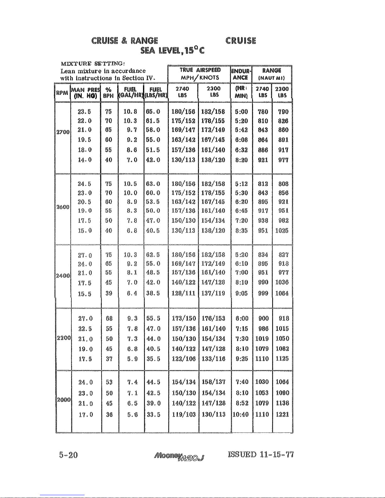
AT
ECONOMY
Page 81
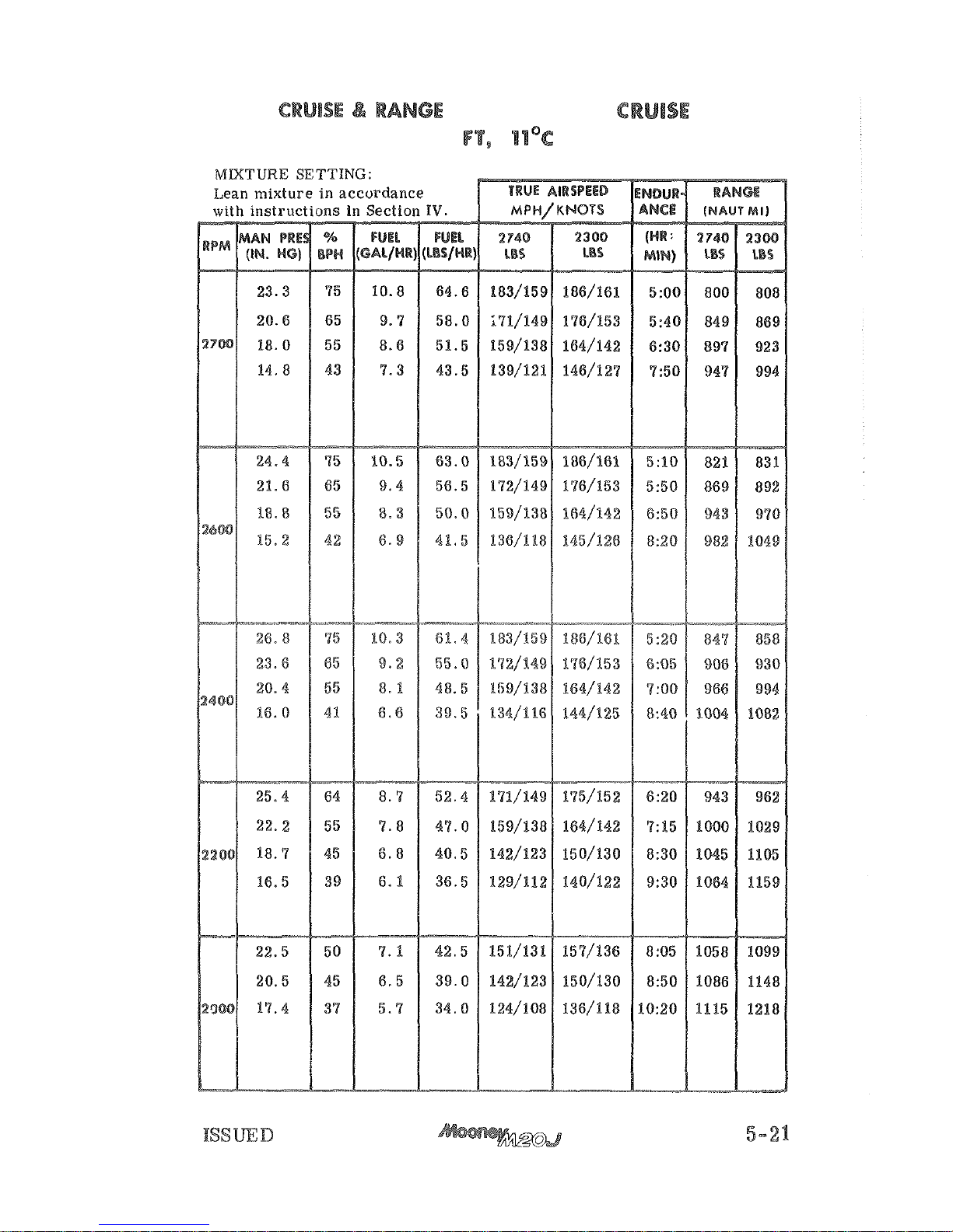
AT
ECONOMY
2000
11-15-77
Page 82
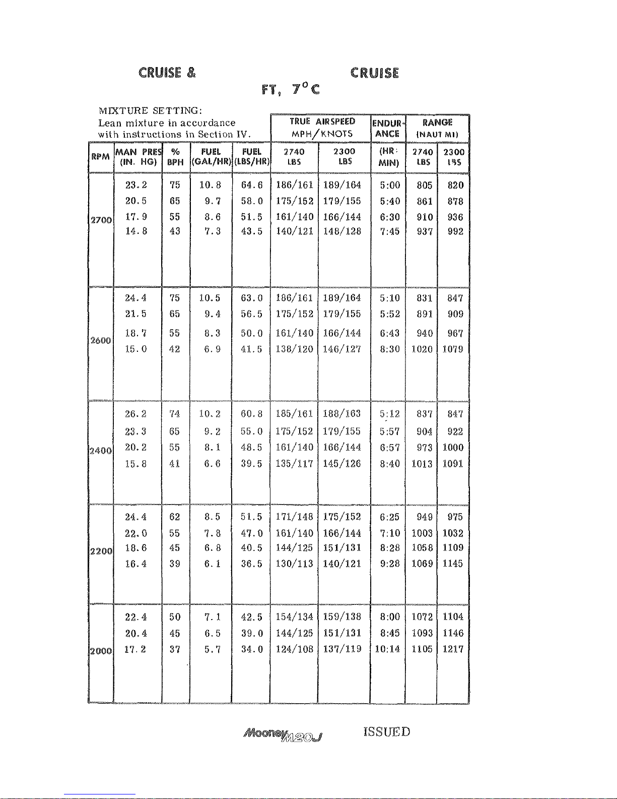
RANGE
AT
ECONOMY
4000
5-22
11-15-77
Page 83
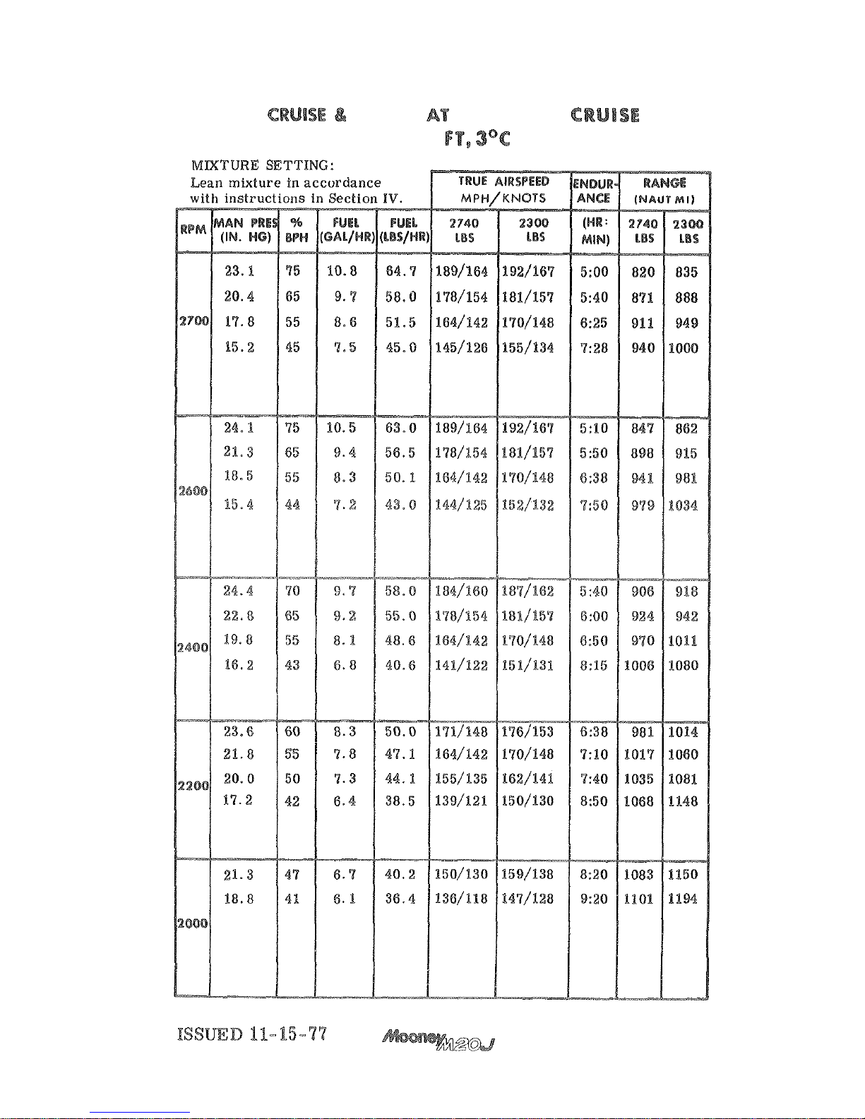
RANGE
ECONOMY
6000
5-23
Page 84
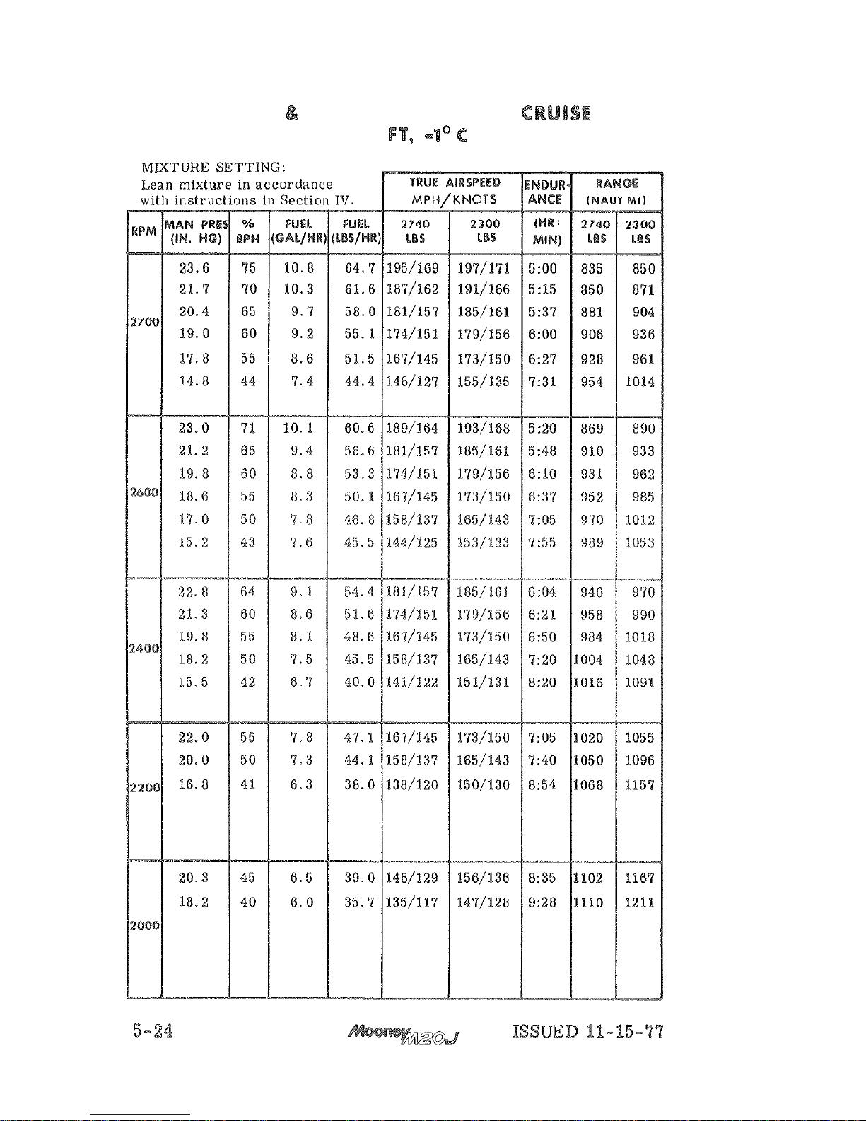
CRUISE
RANGE
AT
ECONOMY
8000
Page 85
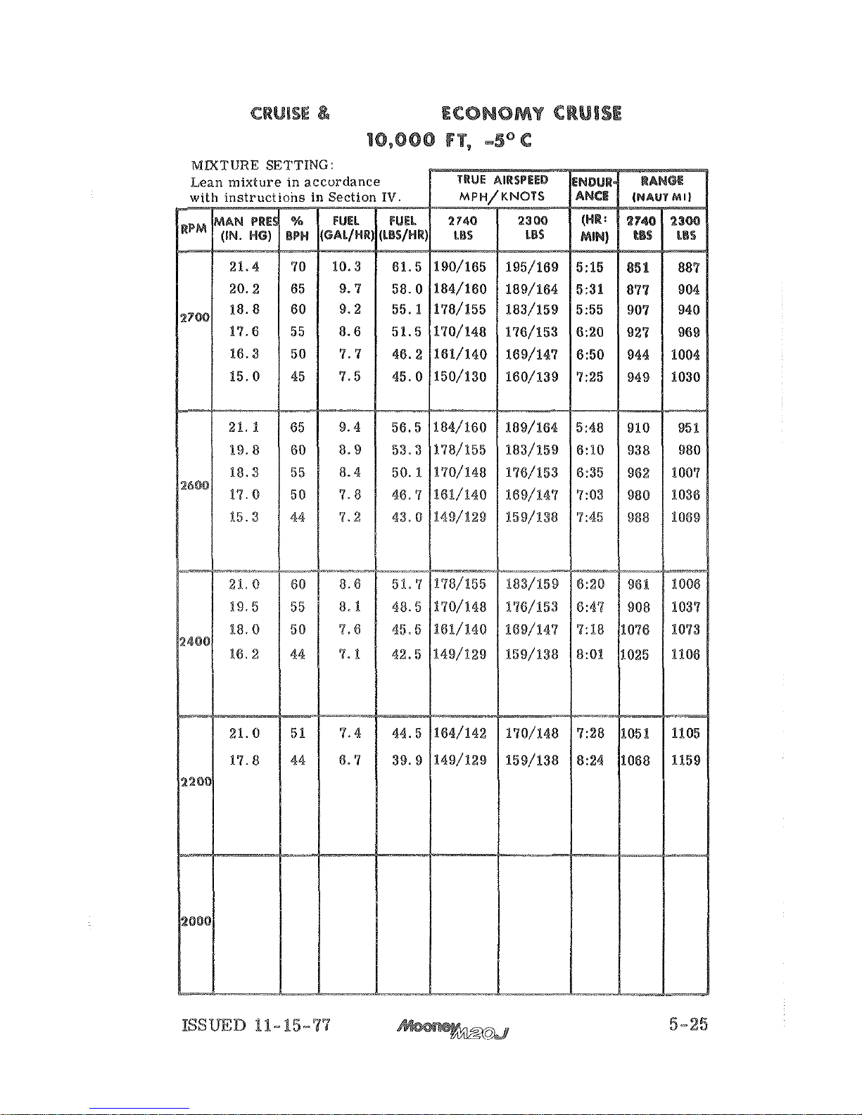
RANGE
AT
Page 86
Page 87
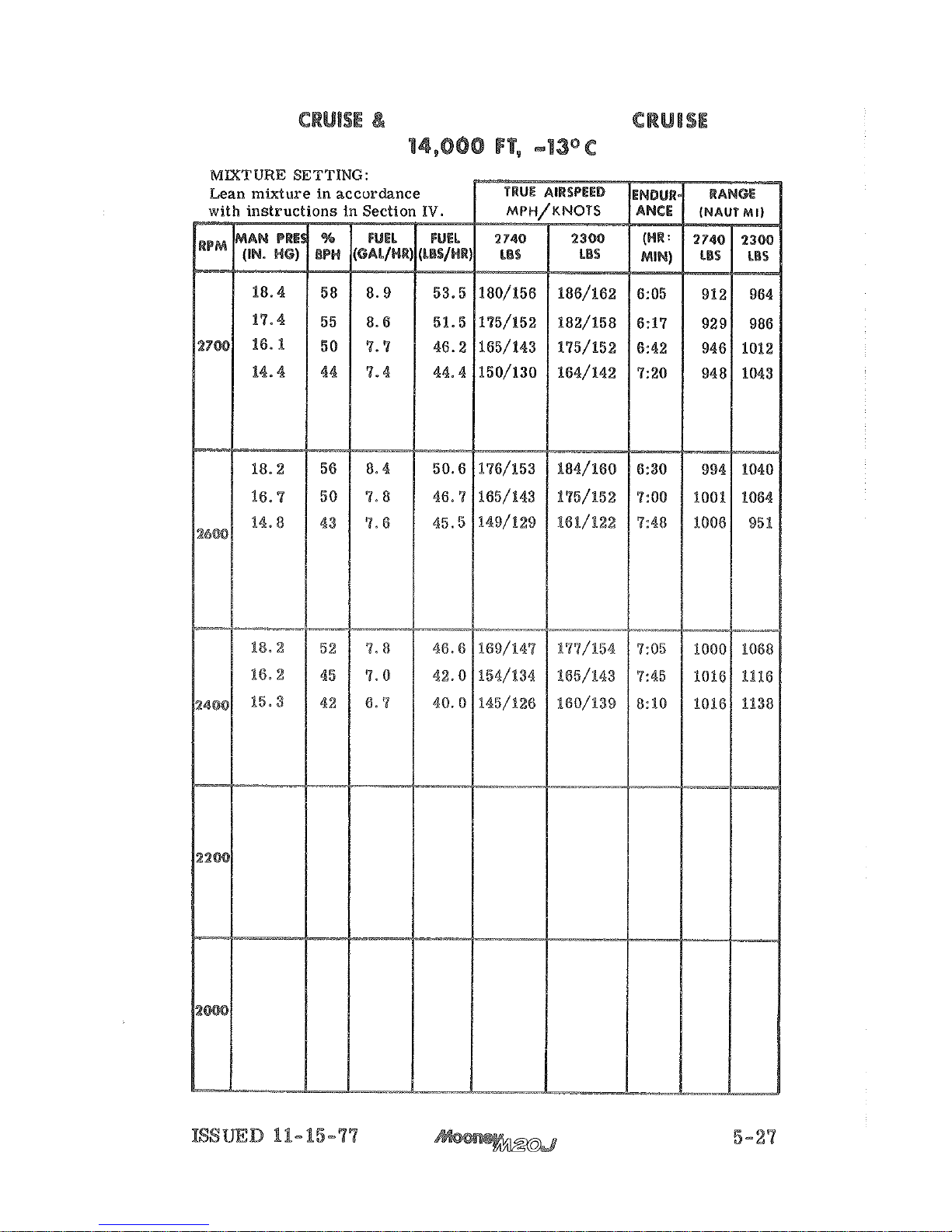
RANGE
AT
ECONOMY
Page 88
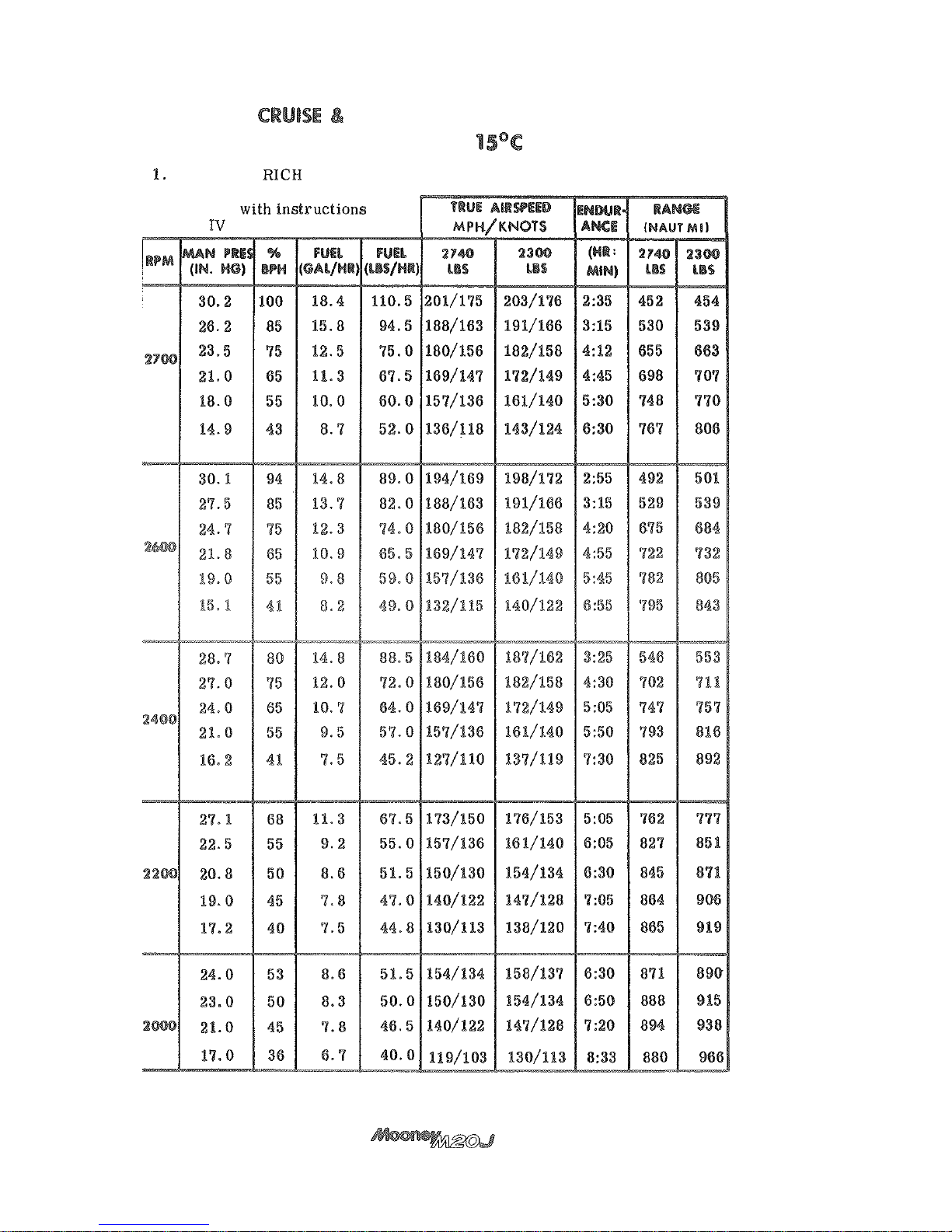
RANGE
AT
BEST
POWER
MIXTURE SETTING:
SEA
LEVEL,
Use
FULL
mixture above
75% power.
2.
Lean mixture in
accordance
Section
at
75% power and below.
5-28
ISSUED
11-15-77
Page 89
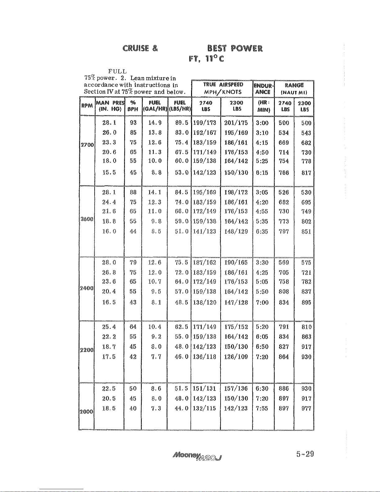
RANGE
AT
MIXTURE
SETTING:
2000
1.
Use
RICH
mixture
above
ISSUED
11-15-77
Page 90
Page 91
Page 92
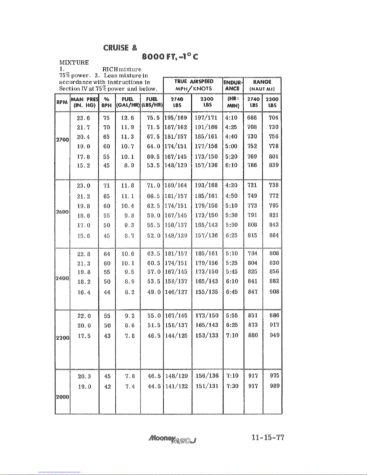
RANGE
AT
BEST
POWER
Use
FULL RICH
above
5-33
ISSUED
Page 93
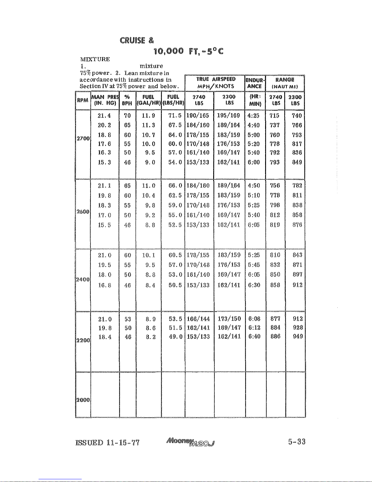
RANGE
AT
BEST
POWER
SETTING:
Use
FULL
RICH
above
Page 94
Page 95
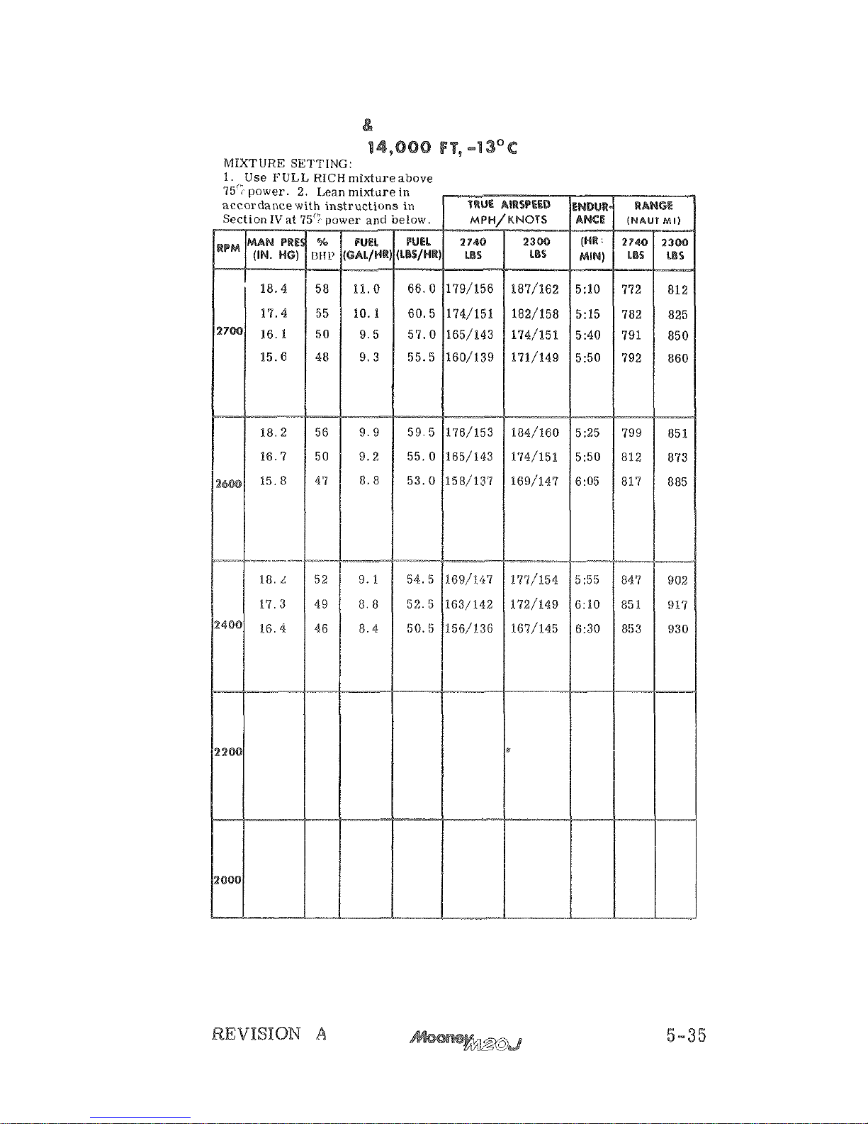
CRUISE
RANGE
AT
BEST
POWER
Page 96
Page 97
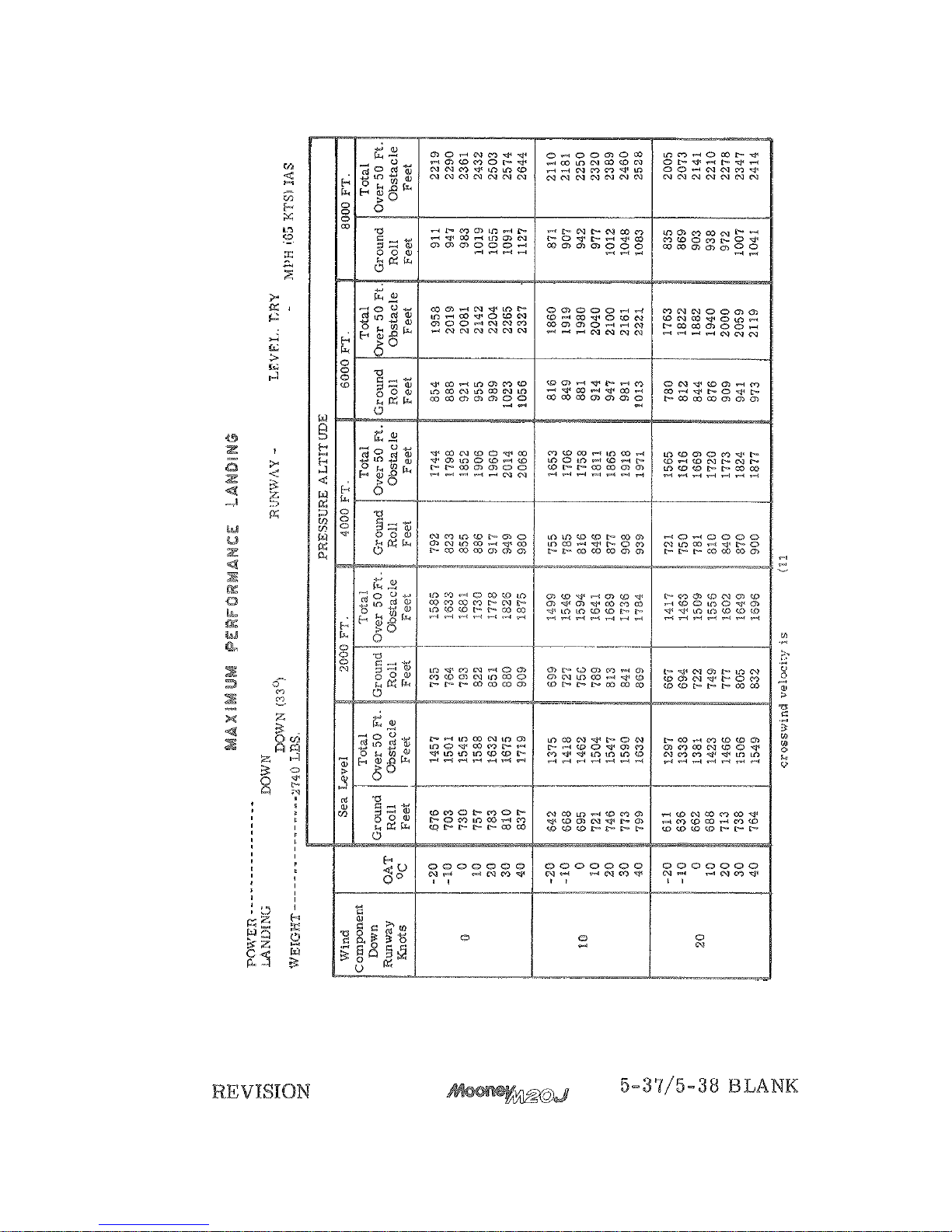
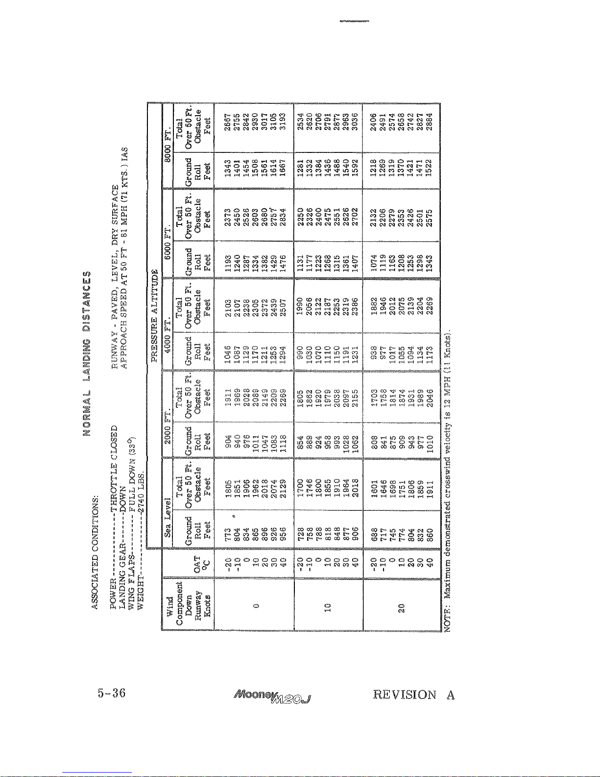
DISTANCES
THROTTLE CLOSED
GEAR
-----
-
--
WING
FLAPS
------
-
-
-
--
FULL
PAVED.
SURFACE
APPROACH SPEED AT
50
FT
75
NOTE:
Maximum demonstrated crosswlnci velocliy
i2
MPH
Knots)
Page 98

Page 99
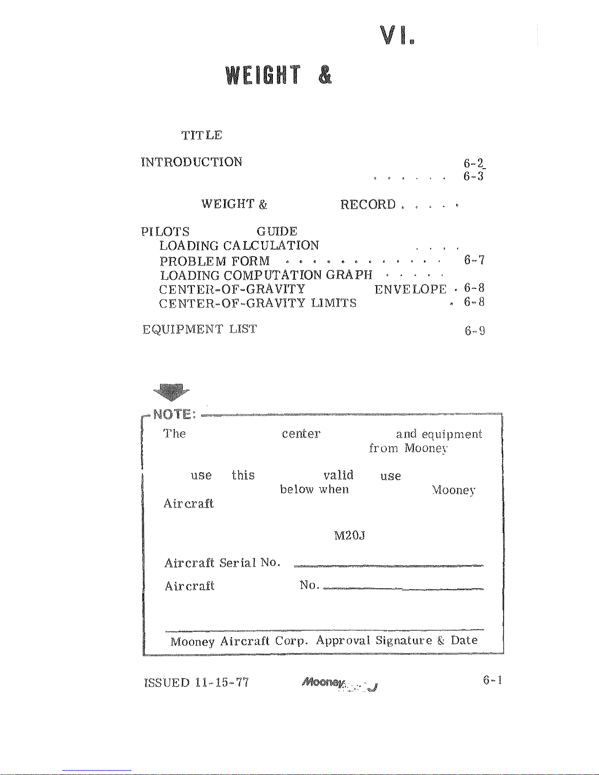
SECTION
BALANCE
TABLE
OF CONTENTS
PACE
...............
AIRPLANE WEIGHING PROCEDURE
OWNERS
BALANCE
6-5
............
LOADING
6-6
6-6
.
6-7
MOMENT
ENVELOPE
.
..............
empty
weight,
of gravity,
list
for
the airplane
as
delivered
Aircraft
Corporation
is
contained
in
this
section.
The
of
section
is
for rase
with
the
airplane identified beiow whela approved by Woonej;
Model.
-
Page 100
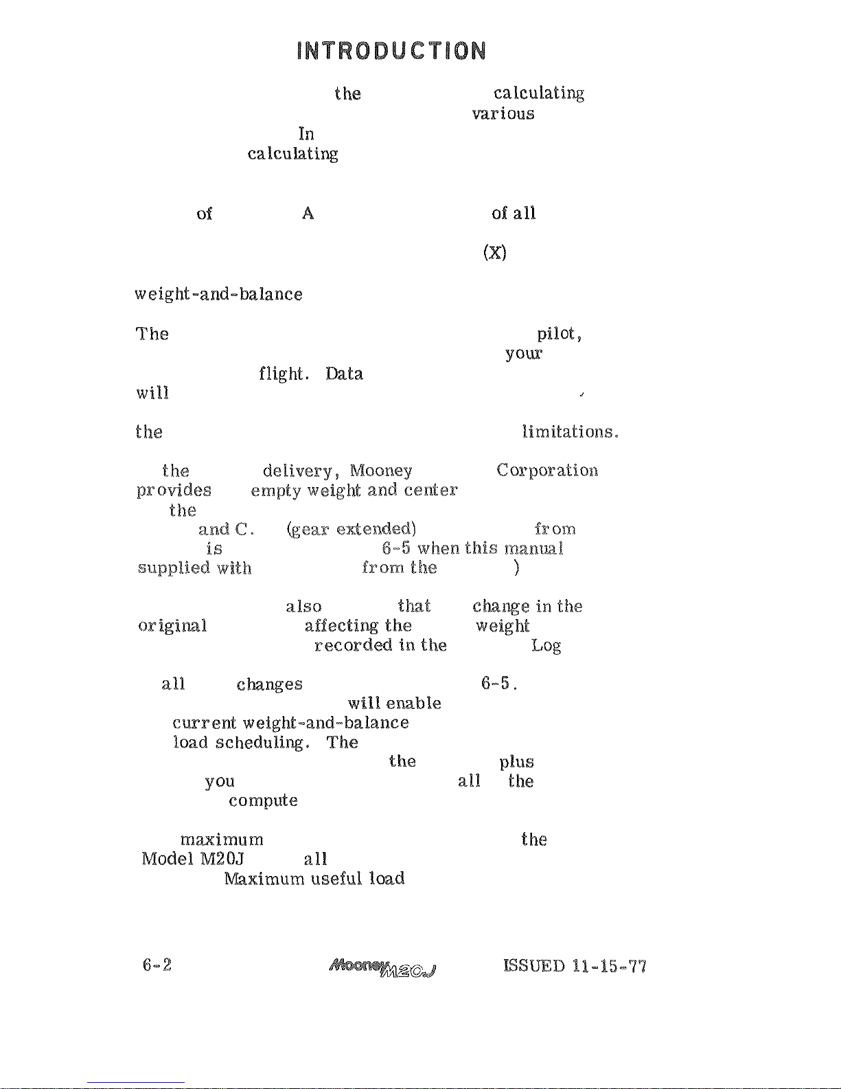
This section describes tkae procedure for calcuiatix
loaded aircraft weight and moment for various
flight operations. In addition, procedures are
provided for
ment of the aircraft when the removal or addition of
equipment results in changes to the empty weight
and
center
gravity.
comprehensive list of all Mooney
equipment available for this airplane
is
included in
this section, Only those items checked
were in
-
stalled at Mooney and are included in the empty
FAA
charges you, the aircraft owner and pilot,
with the responsibility of properly loading your air
-
craft for safe flight* Data presented in this section
insure that your airplane
is
loaded to operate within
-of-
gravity Xirnitatioe~s.
At the time
of
Aircraft
of
gravity data
for
of
individual loadings. (The
empty
weight and
G.
as
delivered
factory
tabulated
ow
page
the aircraft
factory.
FAA
regulations
require
any
center of gravity
be
Aircraft Log Book,
A
convenient form for maintaining a permanent record
of
such changes
is
provided on page
This form,
if properly maintained,
the
for
weight-and-balance data
entered
as
your aircraft 'left the factory, plus the
record
6-5,
is
needed
to
The
under
operating conditions
is
2740
pounds, mximum useful load
is
determined by
sub
-
tracting the corrected aircraft empty weight from its
 Loading...