

PILOT'S
AIRPUNE
OPERATiNG
AND
FM
APPROVED
FLIGHT
HANDBOOK
MANUAL
Advanced
THIS HANDBOOK INCLUDES THE MATERIAL REQUIRED TO
TO
THE PILOT
CONSTITUTES THE
THIS
DOCUMENT
BY
THE FEDERAL AVIATION WEGUUTIONS, AND
FM
MUST
APPROVED AIRPLANE FLIGHT MANUAL.
BE
CARRIED
Trainer
IN
THE
AIRCRAm
--------
FAA
APPROVED:
MOONEV
B.O.
BOX
SERIAL. NUMBER:_"
REGISTRATION NUMBER:-
Airplane Certification
FEDERAL A\llKf'ION ABMINISTWATlON
Fort
Worlti,
761
9351
AlRCRAR
72,
KERRVILLE,
Texas
50
CGORPORATlON
TEm8
Offieo
AT
980280072
BE
FURNISHED
A
ISSUED
REV.
A
RM.
B
FM
APPROVED
applimble
8 - 89
3-90
1-92
In
Normal
to
Mdel
Cetegcay
M2OJ
SIN
based
listed
on
CAR
PART
above
only.
MANUAL NUMBER
3;
3210

MOBNEY
MODEL
M28J
AT
INTRODUCTEON
LTGG
L--"-L=-"
ORIGINAL
REVISION
REVISION
Always destroy superseded pages when inseflir~g
TITLE
"K
page
i
lhru iv
v
thru
I-
1
1-2
1-3
thru
1-9
thru
3-4,
3-2
3-3
thru
3-9,
3-10
3-'11
3-12
Ghi'LI
4-1
4-2 ...
4-3,
4-4
4-5,
4-6
4-7
Ghru 4-12
4-i3
4-94
5-1,
5-2
53,
5-4
5-5
thru
5-49 thru
5-33 1Rru 5-36
....................
A
...................
B
...................
PAGE
...............
...................
..................
vi
..................
.....................
.
.....................
l-fi
.....................
1-10
3-8
...
..................
1
,
3-'I
4.
...
.
.
.
,
...
...
.
.
,
,
5-1
8
5-32
EFFECT~VEE~]
----
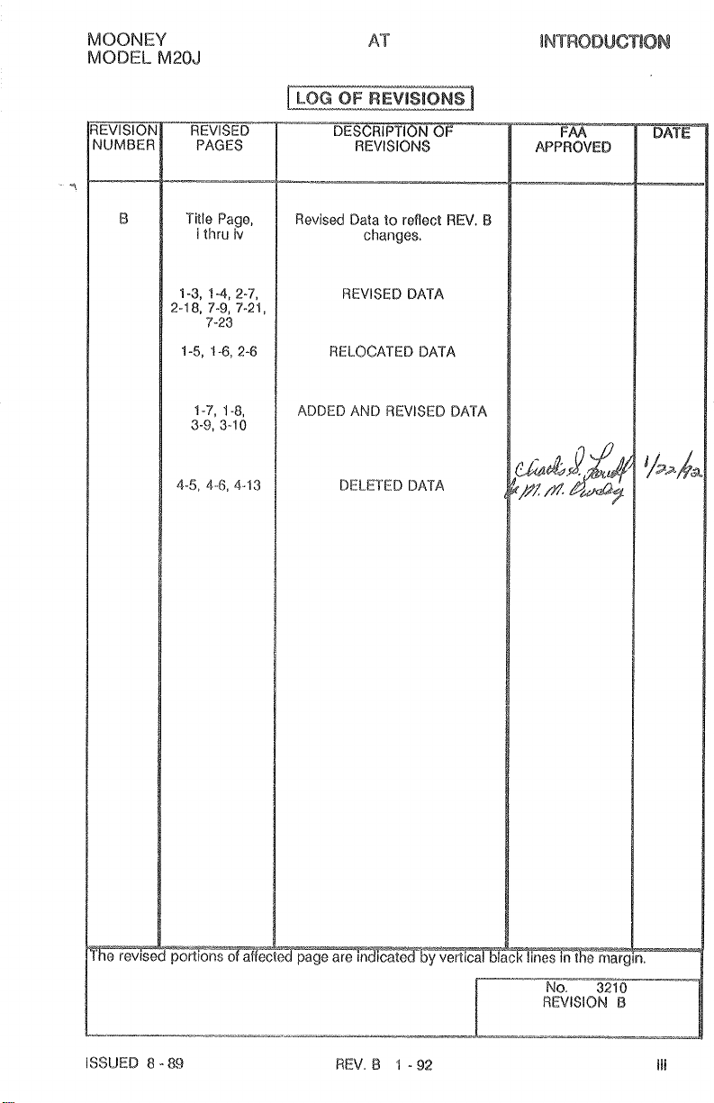
revis4
pages.
8
-
8
9
3
-
90
1
-
92
B
Original
.
B
Original
Original
A
B
Original
Original
.A
.B
.A
Original
6-3
thru
6-6
6-7
lhru
ISSUED 8 -
6-5
6-i
89
.
This POWIAFM
PBHIAFM
i.
effective
NUMBER
beginning
3218
with
1
~~~1810~da
*---
M203,9/N
24-lW14
T
OF
EFFECTIVE
PAQ
MQONEY
MODEL
M20J
7-1 thru 7-8
7-40
...
7-1 1 thru 7-4
7-15
...
8-1 thru 8-5
8-6
8-7 thru 8-4'0
4
0-1 thru 10-4
Original
.B
4
2
.A
Original
.A
.
B
Original
.A
Original
Original
.a
Original
Original
Original
This
PQHlAFM
effective
REV.
B
beginning wLh
1 - 92
M20J
SIN 24-1686-1
ISSUED
4.
8
-
89
MOONEY
MODEL
M20J
MOBNEY
MODEL
M20J
iv
REV.
B
1
-
92
ISSUED
8
-
89
MOONEV
MODEL
M20J
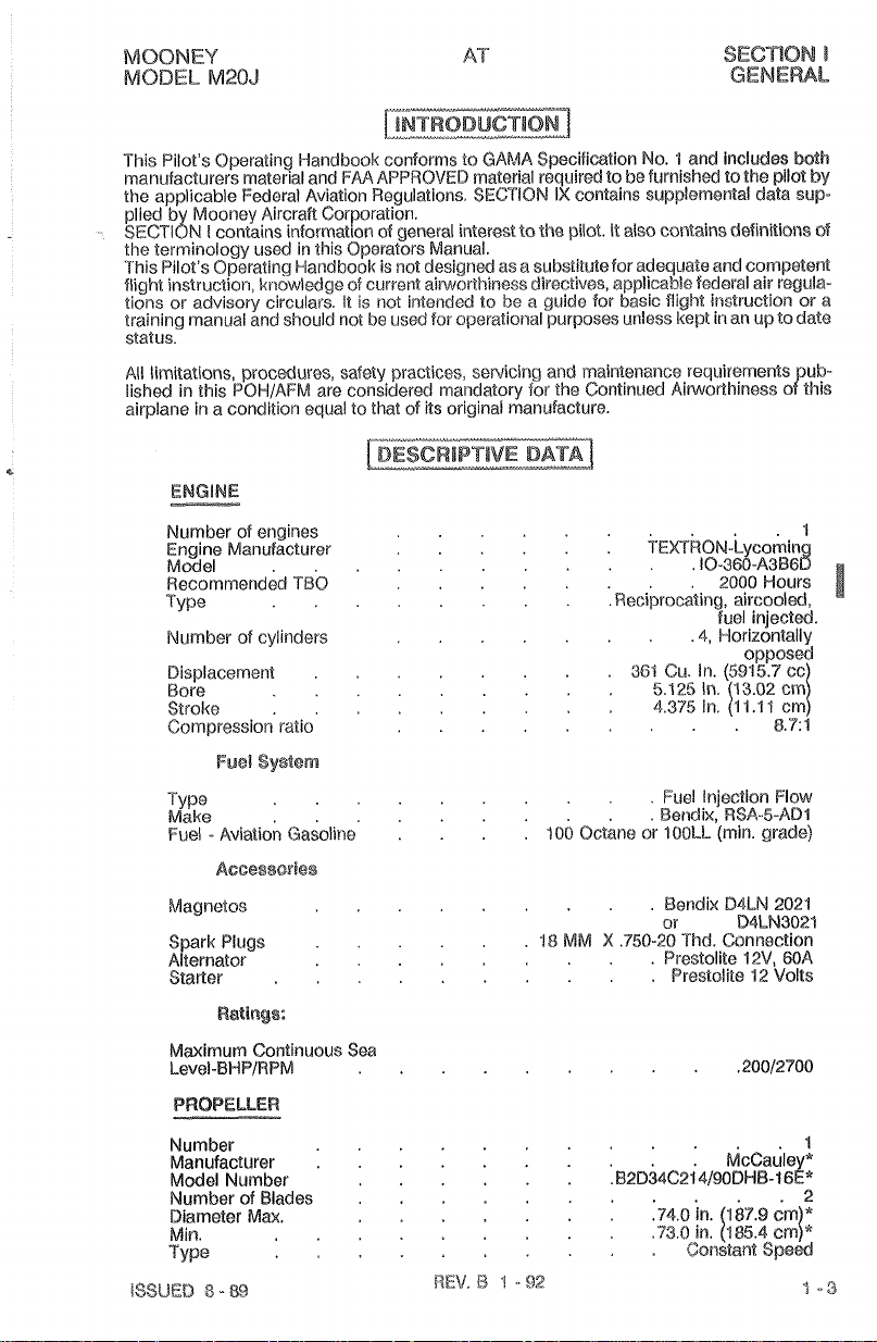
'l'l~is I 'ilot's Ol-,uraiing I le#~dbcro!c conlom~:;
~r>i:lr~t~facttl~i>rs
the applicable Federal Aviation Regulations. SECTION
plied b Mooney Aircraft Corporation.
sEGT~~N
the terminology used in this Operators Manual.
This Pilot's Operating
flight instruction,
tions or advisory circulars It is not
training
status
All limitations, procedures, safety practices,
lished in this POH/AFM are consider& mandatory for the Continued Aiwo~h~ness of
airplane in a condition equal to that of its original manufacture.
Number
Engine Manufacturer
Model
~ecornrnendid
Ty lse
Number of cylinders
Bisplacerner?t
Bore
Stroke
Compression ratio
I
hatoi
ial anti
FA/\
f1I'I"I
I
contains information of general interest tothe pilot.
Haridbook is
kr~owledge ofcurrent aiwrrrtkiness directives, applicable federal air regula-
manual and should not be us& for operational purposes ~rrsless kept in an up todate
of
engines
TC
. .
not
...
..
.....
.
.
.
.......
.
.......
.
.........
E(j
(4/41\9A
1O\/tYl) rr~nleri;ll ~.etluirc?ci
designed as a substitMefor adeq~aate and competent
interlded to
sewicing and maintenarlce requiu~ments pup-
Sl~ocilic;iatior~
IX
contains supplemental d&ta sup
be
a
guide for basic Right instruction or a
....
.
.
...
No.
i
to
it
.Reciprocating, aircooled,
:artcl Illcludas boll1
bo
funii::llotl tc)
also contains dsfinniona of
~~~kON-&comin
361
Cia.
the:
s,ilu(r
4
.10-3m-~3~68
2000 Hours
fuel
injected.
.4,
Horizontally
In.
(591
5.7
8.711
Fuel System
Type Fuel injedion Flow
Make
F5.A
..........
....... . .
..
Aviation Gasolit7e
...
$06
Octane or
Bendix, RSA-5-AD1
lC10Ll.
(min. grade)
Accessories
Magnetos Bendix
Spark
Plugs
Alternator Prestolite 12V, 6QA
Starter Prestoli're
Ratings:
.........
18
MM
X
......
.........
..........
.75Q-20 Thd. Connection
or
D4LN
WLN3024
42
2021
Volts
Ijy
thls
cc
Maximurn
Continuous Sea
Level-BWP/RPM
PROPELLER
~imber of Blades
Diameter
Min.
Type
Max.
...
..........
....
...
.
SECTION
GENERAL
I
MOONEY
MODEL M20J
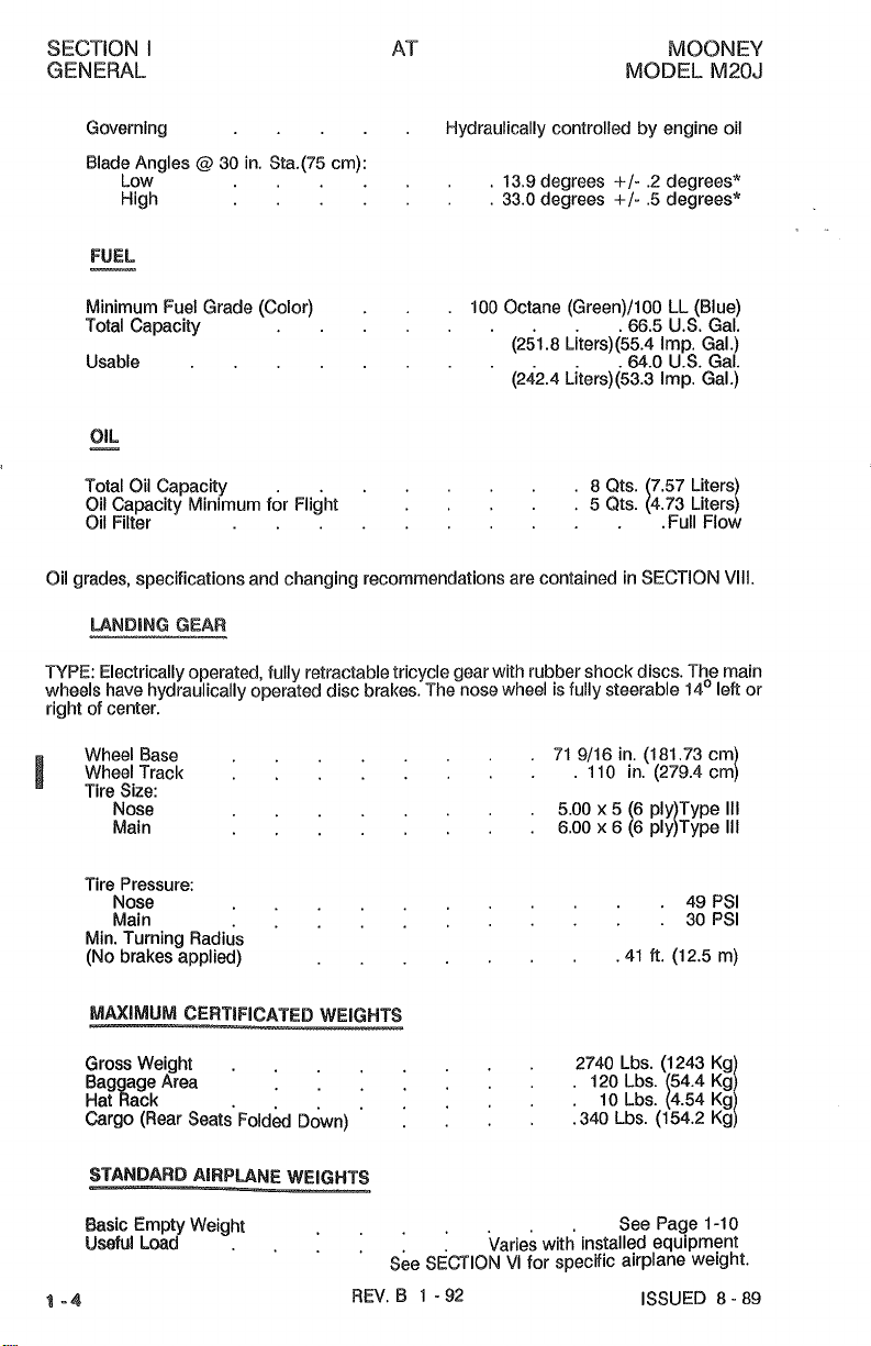
Governing
Blade Angles
Low
High
FUEL
v
Minimum Fuel Grade (Color)
Total Capacity
Usable
Total Oil Capacity
Oil Capcity Minimum for Flight
Oil Filter
Oil grades, specifications and changing
MNDING
TYPE: Electrically operated, fully retractable tricycle gear with rubber shock discs. The main
wheels have hydraulically operated disc brakes. The nose wheel is fully steerable
right of center.
Wheel Base
I
Wheel Track
Tire Size:
Nose
Main
.
@
30 in. Sta.(75 cm):
...
...
.
......
........
.
......
......
recommendations are contained in SECTION VIiI.
I-lydraulically controlled by engine oil
13.9 degrees
33.0 degrees
100 Octane (Green)/100 LL (Blue)
(251.8 b/ters)(55.4 Imn. Gal.)
,-
(242.4
...
+I-
.2
degrees*
+/-
.5 degrees*
.
-
66.5 U.S. Gal.
-~,\--
.64.0
L/ters)(53.3 Imp. Gal.)
8
5 (11s. 14.73 Liter$
u$.
Qts. 7.57 Liters
.Full Flow
~a(
GEAR
14' left or
......
.......
..
.
71 9/16 in.
5.00 x 5 (6 ply Type Ill
6.00 x 6 (6 pldType Ill
(1
1 10 in. (279.4 cm)
81.73 cm
Tire Pressure:
Nose
Main
Min. Turning Radius
(No brakes applied)
MAXIMUM CERTIFICATED WEIGHTS
Gross Weight
Bag age Area
Hat Wack
argo (Rear ~eats'~oidk Down)
STANDARD AlRPURlE
&sic Empty Weight
UMLmd Varies with installed equipment
1-4
........
.........
....
........
......
...
.
WEIGHTS
......
.41
2740 Lbs. (1243 Kg
120 Lbs. 54.4 Kg]
10 ~bs. 14.54 ~g
340 Lbs. (154.2 Kg!
See Page 1-1 0
.....
See
S~fllOkI VI for specific airplane weight.
REV.
8
1 - 92 ISSUED 8 - 89
M.
(12.5 m)
49PSI
30PSI
MOONEY
MODEL
M28J
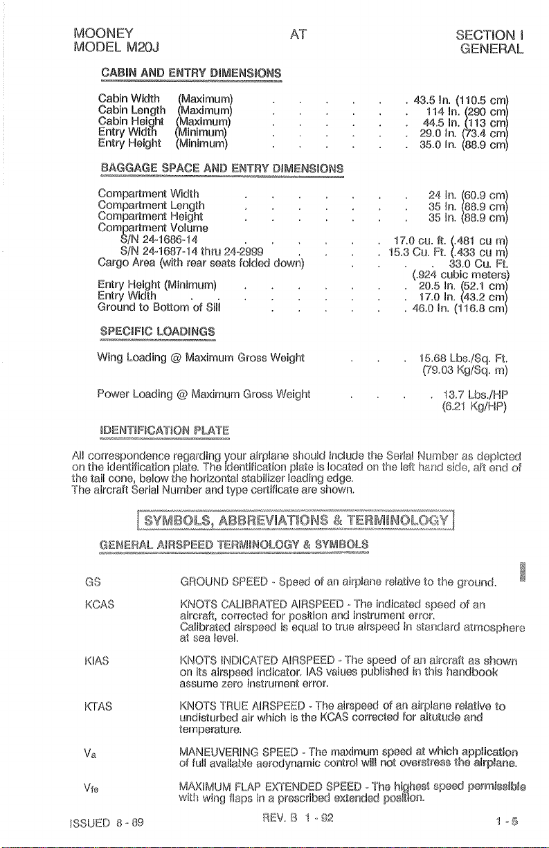
CABllN
AND
ENTRY
DIMENSIONS
AT
SECTION
GENERAL
1
Cabin Width Maximum)
Cabin Length [Maimurn)
Cabin Hei
Entry ~id8 binimum)
Entry Weight (Minimum)
BAGGAGE
Compaf?mene Width
Compafiment Length
Con?par%men% Height
Cam artment Volume
Cargo Area
Entry Height
Entry Width
Ground to Bottom
Wing Loading @ Mwimum Gross Weight
Power Loading @ Maxim~dm Gross Weight
correspundonce regalditlg your airplar:e should i!:clude tho
Ail
oil
the
identification
tile Tail cone, below the horizorltal stabilizer loadirlg edge.
'The aircraft Serial Nurnber and type cel-sificare are si-rown.
24-16%-14
SIN
24-1687-44
ht
Maximum)
SPACE
(with
AND
Zhru
rear seats fold&
(Minitrscim)
24-2'%9
...
csii
Sill
plate. The identification piate is located
...
.
...
..
.
ENTRY
DIMENSIONS
.
..
.
....
.....
,
down)
...
....
43.5
In.
(410.5
.
...
17.0cu.M.
.
15.3
j.924
46.0
...
Serial
on
the [eft
CU.
R.
cubic meters)
In.
15.68
(79.03
Niimbei
!l~atfd
sir:le,
,481
1.933
33.0
(116.8
Lbs.lSq.
Kg/Sq.
cum
cu mi
CU.
as
depicted
aft
ci~s
~t.%.
cm
R.
rn)
et~i
08
G
S
KCAS
KIA$
KTAS
Va
Yf,
GROUND
KNOTS
aircraft,
Calibrated airspeed
81
KNOTS
on its aifspsed indicator.
assume
KNOTS
~~ridisturbd
temperature.
MANEUVERING
of
Ril,UiMklM
with
SPEED
-
Speed
of
CALIBRATED
correcte,d for position and instrument error.
Sea
!BV@/.
iNDiCKrED
zero
irsstrumenl error.
TRUE MRSPEED - The airsped
air
full available aoumynamic contrd
FLAP
wing
flaps
AIRSPEED
is
equal to fr~ie
AIRSPEED - Thc
lAS
irawirich
is the
SPEED
-
Ttse
EKrENDFD
in
a aarescrrbed
KCAS
aur
airplane relative
..
The indicated
airspeed
speed
vailies publisk~&
corrected for aitut~asde and
n~aimum speed at which
will
r~o%
SPEED
-The
ex%ef\ded
lo
the
speed
in
standard
of
PXTI
aircraft as
iin
this haitdbosk
d
an
airplane relative
a?\~e~s$r'@ss
highegt
psWbf2.
SIJ&
ground.
d
an
atmosphere
show;?
to
appiwtion
ti-ie
alrflane.
imfn7hs8Me
1
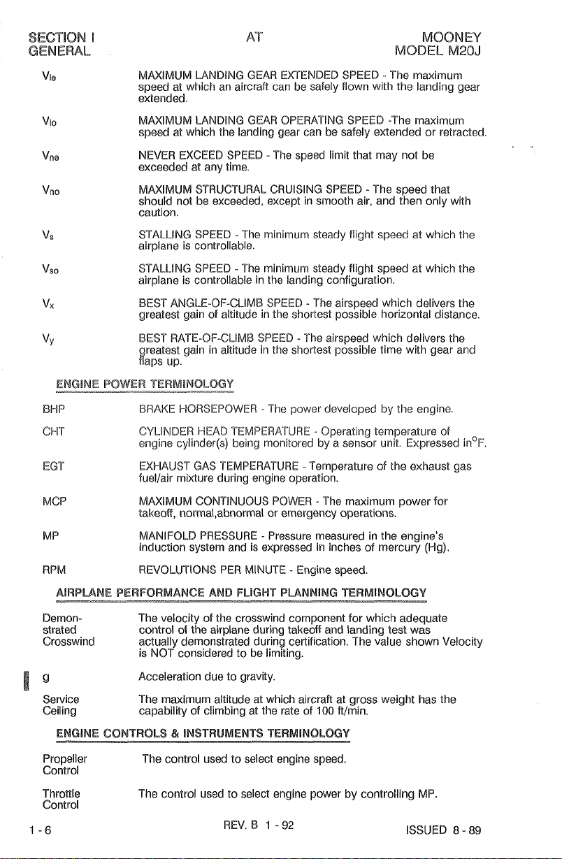
MMIMUM LANDING GEAR EXTENDED SPEED - The maximum
speed at which an aircraft can be safely flown with the landing gear
extended.
MAXIMUM
speed at which the landing gear can be safely extended or retracted
NEVER
exceded at any time.
MNIMUM STRUCTURAL CRUISING SPEED -The speed that
should not be
caution.
STALLING SPEED
airplane is controllable.
STALLING SPEED
airplane is controllable in the landing configuration.
BEST ANGLE-OF-CLIMB SPEED
greatest gain of altitude in the shortest possible horizontal distance.
LANDING GEAR OPERATING SPEED -The maximum
EXCEED SPEED - The speed limit that may not be
exceeded, except in smooth air, and then only with
-The minimum steady flight speed at which the
-
The minimum steady flight speed at which the
-
The airspeed which delivers the
<
-
BEST RATE-OF-CLIMB SPEED
ireatest gain in altitiide in the shortest possible time with gear and
aps up.
BRAKE
BHP
CHT
EGT
MCP
MP
WPM REVOLUTIONS PEW MINUTE - Engine speed.
Demon- The velocity of the crosswind component for which adequate
strated control of the airplane during takeoff and landing test was
Crosswind
%
"
Service
Ceiling capability of climbing at the rate of
ENGlaalf
-----
Propeller
Control
Throltle The control used to select engine power by controlling MP.
Control
CONTROLS & INSTRUMERn 9 TERMINOLOGY
HORSEPOWER
CYLINDER
engine
EXHAUST GAS TEMPERATURE
fuellair mixture during engine operation.
MMIMUM CONTINUOUS POWER - The maximum power for
talteoff, norma1,abnormal or emergency operations.
MANIFOLD PRESSURE
induction system and is expressed in inches of mercury
actually demonstrated during certification. The value shown Velocity
NOT
is
Acceleration due to gravity.
The maximum altitude at which aircraft at gross weight has the
The control used
HEAD
cylincler(s) being monitored by a sensor unit. Expressed inO~.
considered to be limiting.
-.
TEMPERATURE - Operating temperature of
-
to select engine speed.
REV.
B
-The? airspeed which delivers the
-The power developed by the engine
-
Temperature of the exhaust gas
-
Pressure measured in the engine's
100
ftlmin.
.-
1
-
92
(Wg).
ISSUED
8
-
89

ENGINE
Mixture
Control
CHT
Gauge engine opsrstlng temperature is within manufacturers
EGT
Gauge fuel Row mixtures for various power settings.
CONTROLS
&
INSTRUMENTS
-
---------. .
a
Provides
control
therefore the
engine down.
Cylinder
specifications.
Exhaust gas temperature indicator used
mechanical linkage to the fuel Injector rnisdure
to control the size of the fuel
airlfuel mixture. It
head
temperature indicator us& to determine 'that
TERMINOLOGY
-
---
feed
is
the primary method
to
(eon?.)
aperture, and
identify correct lean
to
shut
Tachomefer
Propeller The device that regulates tlie
Governor
METEORQLQGIGAL
Density
Altitude
Pressure
Aititude
AII
instrurv~ent that indicates rotational speed of the engine.
The sped is si.iown as propeller revolutions per I-ninuts
increasir~g or decreasing the propeller pitch, ehrouyl~ a pitch
change mechanism in the propeller hub.
TERMINOLOGY
Above
groussd level
Altitude as determind by pressure altitude anel existiorg ambient
ternmerature. In stardard almos~here (ISA) densitv and mressure
altitude are e
temperalure. %la higher the density altitude.
The altitude actually read from an aitirneter when, and
wl~en, the barometric s~rbscale has
INTERNATIONAL SIANBARU ATMPSPHERE assurnes that
(1)
The air is a dry perfect gas;
$5 ' CelsI1.1~ (59'
inches Hg (19'13.2 mb);
to the altit~ade at which the temperatk~re is
..1).00198~ @ (4.0035~~
CIUTSIDE
obtain& either from inflight temperature iygicatiuns or grorirld
ruieteorologicai sources. It is exyresstx!
The altitude indicatd when Kajllsman VJi;dow
in. klg. or
errors are
ual
For a ejiven bressure aliilude, the higher the
F);
(3)
The pressure
(4)
F)
AIR TEBIIPEBATUFSE - T11e free air static tei?tperata"ure,
10-13.2
MW.
assurnecl
In this !lardbook,
to
be
zc?ro.
(RPM),
RPM
of the snginelpropeiler by
o~?iy
bsc?r~
set to Statiorr Prk?sslare.
(2)
Tho tempesature at
at
The;. te?mperal~are gradient frosl~s~a, level
sea level is
-56.5'
per foot.
C.
iiri
altirnoter
29.92
C
(69.7
is
s~t
to
instriirncnt
sea
29.92
level is
F)
IS
I
Station
Pressure
Arrur
Basic
-D
i-r.mpty
\iYc?igI~t iocaTic3n and
Actual atmospheric pressure at field elevatioil
The
brorizontal distance kom tire refwenco
gravity
(C.G.)
The actrial
equipment (including optional equipmeilt)
weight
d
unusak~k
(3f
an item.
weight
of
tlw
is
actually installed
l~iei
airplat?@
auicflfiili
datum
and ir.tclirdes
ellat
in
the
aircraft.
oii.
to
all
opr?ratiilg
has
a fixed
;It
inc3:ides
tiw @Blit~?P
of
.Else

SECTION
GENERAL
!
MOONEY
MODEL
M20J
Center
of
Gravity
(C.G.)
C.G. Arm
C.G. in
%
MAC
C.G.
Limits
MAC
Maximum
Weight
Moment
Reference
Datum
Station
Tare
Usable
Fuel
Useful
Load
The point at which an airplane would balance
Its distance
tdal rnomerit by the total weight of the airplane.
The arm obtainad by adding the airpiane's individual moments
end dividing the sum by the
Center of Gravity expressed in percent
chord.
The extreme center of gravity iocations within which the airplane
mud be
Mean Aerdynamic Chord.
The
contents as iid~d in the aircrafi specifications.
product d the weight d an item multiplied by its arm. (Moment
divided by a constant is used to simplify balance calculations by
reducing the number of digits.)
An imaginary vertical plane from
distances are measurd for balance purposes.
A
locatiorl alon the airplane fuselage usually giver1 in terms of
distance
The weight sf
airplar~e, and is included
from
Fuel remaining
accordance with governmental
Fuel avaiiable
The basic empty weight subtracted from the rnaxirnurn weight of
the air@aM. This
passengers, and baggage.
from the refere~sce datum is found by dividing the
total weight.
operated at a given weight.
maximum authorized weight
from tk reference datum.
the
chocks,
scaie
for
blocks, starrds,
reading to obtain
after a runout
airplane propulsion.
load
consists
of
the aircraft and its
which all horizorrtal
in
the scale readin. s. Taro is
tho
aciuai
nest
has bzen
regula.tions.
of
the pilot, crew
if
suspended.
d
mean aerodynamic
etc.
used when wsighing
:,el)
ailplane weight.
completed in
if
applicable, fuel,
deducted
an
REV.
B
1 - 92

MOONEY
MODEL. M20J
SECTION
i-IMITATIONS
I1
Number of Engines
EngineManufacturer
Engine Model Number
En ine Operating Limits for Talteoff
an$ Cont~nuo~ts Operations:
.......
.....
.
T~~Tk~N~~corning
.lo-360-A356D
Maximum Power . ,200 BHP
MaximumEngineSpeed
Transient Engine RPM Limit
Max. cylinder nead iemperalure . .473OF
~aximum'~ilTemperat~~re
Oil Pressure
Normal Operating
Minimum (IDLE ONLY)
Maximum (cold oil)
Fuel Press~ire
Minimum
Maximum
Fuel Grade (Color)
Number of Propellers
Propeller Manufacturer . . .
Propeller Model Number
Propeller Diameter:
Min.
Max. (No cirtoff allowed)
Propeller Blade Angles @ 30 111. sta.:
Low
...........
..........
.
........
..........
....
.........
High
Propeller~~er~tingiin~its
,
.
.
,
.
......
........
,
..,.
.....
.......
......
.
,
.
.
...
......
.
.
,
.
...
.
for 3 seconds or less
. 245O
. . (1
,
,
. . 14 PSI
100113b (Green)
100LL. (Blue)
.
.
82~34~2i4/90~H~-l6~
..
73.0 In. (185.4 cm)
74.0 In. (187.9 cm)
13.9O -&-I- .2O
........
.
,
.
,
. . 2700 RPM
33.0~
100LL fuel is calibrated at 5.02 lb/ga1.(.69 Kylliter)
1001130 octane fuel is calibrated at 6.0 lblya1.(.72 Kglliter)
1
2700 RPM
2970 RPM
(246
C)
18'
C)
60-90-PSI
25 PSI
100 PSI
30 PSI
.I
McCauley
+I-
.so
F
No
F/W
APPROVED
ISSUED 0 - 89
I
NOTE
cutoff allowed on propeller
I
when
de-ice boots are installed.
AIRPLANE
i'LIGI-II
I\JIANUAl,
2-5

SECTION
ll
LIMITATIONS
INSTRUMENT REDLINE
Tachometer
(MINIMUM
1-!Mi9
MOONEY
MODEL
GREEN ARC YELLOW REDLINE
(NORMAL
OPERATING)
ARC
(CAUTION
RANGE)
M%OJ
--
g4'-
LlMIp
Cylinder
Temperature
Oil
Oil Pressure 25 PSI
Fuel Pressure Radial 14-30 PSI
Head
Temperature
Red
Line
Min. 14 PSI
60
-
90
PSI (IDLE
25
ONLY)
-
60
*
PSI
- - -
1
NOTE
1
Refer
ts
Section on
TEmRON-Lycoming Engine Maintenance and Qpewtore Manuel
Engine Speciflmtions and Operating LimRs lor recommendd
cruise power and ternpenthare limbtions.
---
---
(
NOTE
I
A
reduced fuel quantity indicator is install& in each tank. The LaoHom
of
these indicators shows the
umble fuel level
---
25
U.S. gallon
in
each
(94.7
&nk.
I&%)
(20.8
---
1
NOTE
1
An optional visual fuel quantBy gauge may be inHall& on asp of each
tank end
is
to
be used
- - -
as
a reference for refueling
Banks
100
PSI
30 PSI
IMP. ~a1.y
only.
ti
)
Standard Tanks: (2)
Total Fuel:
Usable Fuel:
Unusable Fuel:
Fuel Grade (and Color):
100 Octane
1OOLL
..
AIRPLANE FLIGHT
2
-6
.
........
........
.......
....
...
MANUAL
content limited to 2 cc per gallon is also appro\/&.
REV,
B
minimum grade aviation
.
(low lead) aviation fuel (blue) with
1
-
92
33.25 U.S. Gal. each
(126
Liters)(27.7 Imp. Gal.)
bers)(55.4 Imp. Gal.)
(252
iiters)(53.3 Im Gal
(247
(9.5 Liiers)(i.l Imp. Gal.)
.
66.5 U.S. Gal
.
64.0
U.S. Gal
2.5
U?i.
fuel
(green).
a
Gi)
Imd

MmNW
MODEL
MaJ
To
rsdiuce the possibility of ice formation within the eireraft or engine fuel
system
qualities
add other additives to the fuel system due to potential deteriorating effects
M
Is
ermismble to add
N~T TO
within the luel aystem.FUEL
EXCEED
ISGPROPYL
1%
of the
foUll
alcohol to the fuel supply in
luel volume per
LIMITATBONS
LIMITATIONS
tank.
SECTION
DO
NOT
II
Maximum Weight (takeoff and landing)
Maximum Weight in Baggage
Maximum Weight in
Maximum Weight in Car
(Rear seats folded
Most Foward
Intermediate &sward
Forward Gross
Aft
Gross
MAC
(at Wing Sta.
Datum (station zero) is
bolts, and
33
inches((34 cm) fotward of the wing leading edge at wing station 59.25(150 cm).
Hatrack
o Area
downy
.
.
.
.
94.m)
(238 cm)
ti
inches(42.5 cm) aft of the center line
.
.
.
.
2740 ib.(I243 Kg.)
Compfiment
.
.
....
.
Fuse. Sta. 41.0 IN.(903 cm) @ 2250 kBS(1120
.
Fuse. Sta. 41.8 lN.(106 cm)
.
.
Fuse. Sta. 45.0 iN.(143 cm) @ 2740(1243 K
.
Fuse. %a. 50.1 lN.(126 cm) @ 2740 lb.(4243
. .
.
.
(54.4 kg.) @ Fuse. Sta. 95.5
(4.54
~~.j
@
&use. Sta. 119.0
(li4.2 kg) @'Fuse. Sta. 70.7
13.4%
@
2470
LBS.(1120
14.7%
20.1
38.7%
.
.
.
59.1 8 IM.(I50 cm)
of
the nose gear attaching
.
4201b.
10 Ib.
.
340 ibs.
MI48
WIA~
%
MAE
MA(!'
M
M
K
)
)
)
)
I
This airplane must be operated as a Normal Category airplane.
including spins, are prohibited.
lllllllllllllllllll
//WARNING//
1111111/1/////////
nd
been
power.
REV,
B
Y
demsnswatd
-
92
(m.0
Ibs.,
and
may
AIRPIANE
s@led&
FM
APPROVED
fSSLJEB
Takeofl maneuvers, pr01ongd sideslips or steep descents when the
fuel
tank
lMP*
8 - 89
Gal.)
conDiwe less than 8 gallons
of
fuel
&we
Acrobatic
30.3
Biters,
cause
loss
FliGMT
maneuvers,
6.8
d
MANUAL.
2-7

SEC;TION II
LIMITATIONS
Up
to
290
foot altitude
loss may
---
I
MOTE
-
-
occur
I
-
during
stalls
at
mexlm~m
MOON&\/
MODEL
weight.
M20J
Slowthrottle movement required at airspeed above
movement may result momentary propeller WPM overspeed.
-"
FLIGHT
Maximum Positive Load Factor
Maximum Negative Load Factor
Pilot
Maximum Passenger seating configuration
Up
Flaps
Flaps Down
Flaps Up
Flaps Down
............
(33
O)
...........
/
If this airplane is nd equipped with an approved oxygen system and flight operations above
12,500 feet are desired, this airplane must be,
accordance with FAR
with avionics in accordance with FAR
23.1441,
..--.w-p.*-
-..----,--"-----,,..--
LOAD
....
.......
.........
1
FLIGHT
OPERATING
(2)
operated in accordance with
91
or FAR
165
FACTOR
CREW
KIAS. Above
LII~
f
465
KiAS, rapid throttle
---"
......
LIMITATlON8
(1)
equipped with supplemental oxygen in
135.
1
FAR
91.32
and
+3.8g.
+2.0g.
-1.5
0.0g.
(3)
equipped
g.
.I
3
-@
-
This is a Normal Category airplane approved for VFRIIFR day or night operations when
equipped in accordance with FAR
DO
NOT OPERATE IN
Autopilot Limitations - See SECTION IX.
The following equipment was approved during Type Certification and must be installed and
operable for each kind of operation as specified.
The
KlWBB
OF OPERATION
equipment
91.
as
r~ulrd
BEE
NEXT
KNOWN
-
-
-
I
NOTE
I
-
- -
EQUIPME#$
by
epplkable
PAGE
FOR
ICING
CONDITIONS.
list
may
operating
L18Tll4G8,
not
include
rules.
all
the
FAA
AAPPROVEE
ISSUED
8
-
139

MOONEY
MODEL
M20J
EXTERIOR
The following placards must
tions specified.
be
installed on the exterior of the alrcraft
at
the
loca-
I
TIRE
TIRE
FUEL-100
?DOLL (ElLU&
ON
FUEL
TOWING
ON MNN
ON NOSE
GREEN)
32
U.S.
TANK
LIMITS
PRESSURE
(207
GEAR
DOORS
KPA)
PRESSURE
GEAR
MIN.
MI
CAPS
-
(338
DOOR
or
OCT.
KPA)
DO
50
4-9
FUEL-I00
IOOU
26.6
NOT
(BWt!)
IMP
PSI
-761
PSI
GREEN)
MIN.
GAL
USk3W.E
PUSH
or
OCT.
I
I
-009
DO
NOT
TOWING
ON INBOARD END OF
EDGES
I
FAA
APPROVED
ISSUED
AND
8
-
89
EXCEED
LIMITS
NO
WS,
WlNG AHEAD OF FLAPS
WlNG LEADING
ON LEADING EDGE
STABILIZER
OF
BOTH
STEP
-009
OF
AND
SIDES
AIRPLANE FLIGHT MANUAL
HORIZONT881.
TWUNG EDGE
OF RUDDER
-
2-17

SECTION
II
LIMITATIONS
AT
HOIST POINT
MOOMEY
MODEL
M2QJ
UNDER
EACH
FUEL
WING NEAR
ON UNDERSIDE OF WINGS
DRAIN PITOT DRAIN
SUMP
DRAINS UNDER LEFT HAND WING LEADING EDGE
(2
PLCS)
NEAR FUSELAGE
GASCOLATOR STATIC
UNDER FUSELAGE
NOSE WHEEL WELL
AFI OF TRAILING EDGE
UNDER TAILCONE
DRAIN
AFT
OF
WlNG
MRPME
2-18
FLIGHT
MANUAL
FAA
APPROVED
ISSUED
8
-
89

MBONEY
MODEL M20J
AT SECTION
EMERGENCY
PROCEDURES
1II
POWER
Emer ency Locator Transmitter
Seat #eltsl~houlder I-larnesses SECURE
Cabin Boor
Fuel Selector
Mixture
~agneto/Stal"ler
Win
~anBing bear
Approach Speed
Master Switch
POWER
Emergency Locator Transmitter
Seat Belts and Shoulder Harnesses
Cabin Door UNMTCHEB
Fuel Selector
Throttle
Mixture
~a~netol~tarter
Wing Flaps
Master Switch
Approach Speed
Wings
PROPELLER
OFF
-
GEAR RETRACTED
OR
EmEHDED
.
...
......
..........
..........
.......
Fla
s
......
.
DO~N
...
.......
ON - GEAR
RETRACTED
..
.....
..........
........
..........
..
.........
.....
..........
...........
...
PROPELLER
OVERSPEED
.
~ull
DOWN
or
UP
DepeMing on fsrrain
OFF,
~ull
As Slow As Possible
ARMED
UN~TCI-IED
IDL~
(33'Be
prior to lading
~LECURBFF
D~WN
CUTOFF
71
ARMED
.SECURE
.CLOSED
Keep
OFF
OFF
me$)
KlAS
OFF
(%
OF
"7
LEVEL
Throttle
Oil Pressure
Propeller
Airspeed
Thronle
FUEL
Check Mixture ENRICH
Fuel Selector
If condition persists,
MADE
BE
ELECTRICAL
wol@ge
Alternator Field Circuit Breaker
IB
1.
Reduce electrical load.
2.
Land,
ISSUED
8 - 89
.......
.....
....
...
...
LOW
FUEL
FLOW
B~CRE~~SE, set if any contrd avaliable
AS
RE~UIREB to maintain
.
.
.
R~M
bf3iow
..........
AS SOON AS PRACTICABLE.
ALTERHATOR
mming
c~.cun
when practical, to correct malfunction.
use ~ue1'~oo~t Pump as necessary and
OVERVOLTAG
light
break%
iiluminetd
will
not
E
stmdyIAtwmtor GIB
reset,
thi
REV.
....
may
.
RESET or PULL out, then
kllowaing
B
4
-92
promdur~s
Fuliied TANK
~$\N~ING
be
&lpmd.)
are
rqui~:
RmARB
CkiECK
.REDUCE
2900
RPPd'l
SHOULD
PUSH
IN
3
-9

SECTION
ll!
EMERGENCY.
PROCEDURES
AT
MO0NEV
MODEL
M2QJ
ALTERNATOR OUTPUT
Vobge
wrning light fiaahing)
RadioMaster
Master Switch
If
Wamin
Non-Essentid~lectrical Equipment
Ammktter
Alternator Field Circuit ireaker
Non-esential electrical equipment
Airspeed
Landing Gear Actukor kircuii ~redker
Gear Switch
Manual Gear
for char ing condition as each unit
-
A
trippd main aiternator circuit breaker can only be causd by a shofld
allemator eircuk and annd be correct& by reseHing the breaker. This
be
should
time.
non-essential
praeti-l. Wepir the malf~ndioning afternator prior to nex$ flight.
UNDING
FAILURE
......
LQM
is still fkshiw, the lollo~m step are rquired:
It still slowin discharge:
LAND AS SOON AS PRACTICABLE
verifid by aHempting to reset the breaker not more than one
If
this fails, pull allernator field circuit breaker. Turn off all
eledriml quigment and terminate the flight
GEAR
OF
UNDlNG
~xtension hec&nism
LOW
AND AMMETER
SHOWING
.....
....
dr
~ledtrical' Equipmeni is turned OFF
..
Turn OFF one at a time
...
I
GEAR
. .
NOTE
P
TO EmEND
...
OFF io conserve battery power
I
ELECTRICALLY
..
...
.
L~TCH
to engage manual extension mechanism
FORWARDILEVER
DISCHARGE
:
OFF: then ON
...
a8
soon
432
- - -
I
NOTE
I
---
Slowly pull
"T"
handle 1 to 2 inches (2.5 to 5.1 em) to rdate elutch
mechanism
and allow
it
to engage drive shafi.
OFF
.
CHECK
PULL
a8
KIAS or less
PULL
DOWN
BACK,
*
T-Handle
Visual Gear Down Indicator
Continuing lo pull on T-Handle after
actuator; electrical retraction
Return lever to normal position and secure with latch. Reset Landing Gear Actuator Circuit
Breaker.
Do not operate landing gear elecMcall with manual edension system
....
GEAR DOWN
- - -
SYSTEM MAY
a(d
li
ht ~llumnated; §TO# when
BE~OME
. .
by
,vNF"NM,"
"
CAUTION
'-,
N N N N N
MAY
eliminated.
lllllllllllllllllii
engasJ
REV.
8
1
-
92
.
.PULL
(7
to
20
RE~URN
DAMAGED
vieiing from directly above the indicator.
GEAR
NOT
until ear is down and Ipcked,
resistance
- - -
CHECK ALIGNMENT
"
DOWN
light
be possible until binding is
ON will
times
1s felt.
bind
ISSUED
8
-
89

MOONEV
MODEL
M20J
Windshield
Cabin Air
9.
Fuel Tank Sump Drain
Wi
Wfeel Chock
Tank Vent
Tiedqwn ~o~es~chains
bndin@Taw~ Lights
Fuel Tank
used
The
Wing Pip, Lights
Aileron and attach points
Flap and attach points
Contrd Linka es
General Skin
10.
Inlet
Right Wing
ht Main Gear, Shock Discs, Tire, Doors & iJnkage
The
optional
rduc&
$0
indimte
-
fuel
visual
purposes
tk
8ondition
Baggage Door
RETURN
TO
COCKPIT - MASTERIROCKER
AT
NORMAL
...
......
.
...
.......
....
...
C~ECM'QUANTIW-SECUREGAP
SECTION
IV
PROCEDURES
BRAIN until clear
. .
INSPECT
REMOVE
UNOBSTRUCTED
INS$ECP
REMOVE
lenslb~bs
---
I
NOTE
(
-
-
indiatoe
usbie
fuel
Lens
is
lomt&
fuel
mpcw
quantRy gauge
only;
DO
...
........
.....
.
.
.
~er'& irrs'ide ~aich meckhism is properly secured.
-
In
the
fillor
neck.
This
IMP.
- - -
1
NOTE
-
NOT
01
gel.)
-
-
use
25
1
is
fw
U.S.
lo
be
pefl@M
gallons
ua@d
(94.7'
far
p~ial
check.
indimtear
IBers)
.......
INSP~CI-R~MO~E
(Check outside handle operation)
SWITCHES
ice,
Verify SECLIRED
is
(20.8
refueling
INSPECT
INSPECT
INSPECT
INSPECT
snow
or
frost
OFF
I
BEFORE
Prefiight Inspection
Seats, Seat BeltsIShoulder Harness
MagnetolSlafler Switch
Master Switch
Radio Master Switch
Fuel Boost Pum
Alternate Static gource
Pitat Heat
Throttle
Propeller
Mixture
Cowl Flaps
Parking Brake
Wing Flap Switch
Cabin Vent
Cabin Heat
Defrost
Fuel Selector
Directional Gyro (iiaveliree switch)
Circuit Breakers
Emergency Locator
Radios
Radio Blower
Landing Gear Switch
RED Emergency Gear Handle
InternalAxternal Lights
Passengers
ISSUED
8
.....
.....
.....
.....
-
89
...
...
....
....
....
...
...
....
....
~ratkjmker
....
....
.
.
.
.
.
. .
.
REV. B
STARTING
.....
.
.
.
.
.
.
.
..
.
.
.
.
.
.'.
'
:
.
.....
.
....
.
.
1
-
92
CHECK
.
S~ FWE~UE~CIE$ (~ot&i iial wdios)
CHECK
~mergenc~l~enerai Information briefing
I
ABJ~~ST
SLAVED
-
Master Switch
DO~N
COMPLUED
&
SECURE
OFF
OFF
OFF
OFF
PushOFF
PUSHOFF
FULLESTTANK
(if
Install&\
CHEC~
ARM
03,
then
OFF
DOWN
~LTCHED
. .
OFF
1

SECTION
NORMAL
!V
AT
PROCEDURES
Refer to SECTION IX for Optional Equipment Checks.
Obtain local information prior to engine star%.
NNNNNN
"CAUTION
N
N
When bHeq will not stafl engine, inspeaion should be conducted to
determine
sewicing of the hnev is essential and charging for at Beast one hour
shovid ge done before engin?
circutta may be damagd
reason. If determination is made that benev voltage is low,
i!
11
aircraft
"
,.,
N
N N
%tap%@. The
bBeq
8s operat& with a low balBew.
or other electrical
MOONEY
MODEL
M20J
Throttle
Propeller
Mixture
Master Switch
Annunciator Lights
Fuel Boost Pump
Mixture
Propeller Area
MagnetolStarter Switch
"START
Cranking should be limB& to
Mixture
Throttle
Engine
Ammeter
Fuel Flow Indicator
...
.
.
.
.
.
(Ali lighis except
.
...
POWER"
between
warning light should illuminate when magnet@/stefler
switch
cnnking periMs to permit the sbfler to cool.
.......
Oil Pressure
...
....
vurn
.......
.
.......
Y~I-ARV
POWER
to ~dablish Pressure, then
.
...
....
release
-
-
-
1
NOTE
1
-
-
--
is
in
"START
- -
-
(
NOTE
(
-
- -
30
seconds and several minutes allow&
.
CH~K
G;REEP;~
STOP
~dg.
U.
. .
O;N; observe negative movemet of needle)
PUSH "T&ST/USEDU button MOMENTARILY
to stop digits from flashing.
TURN and PUSH to START
40
BOTH
postion.
Move slowly and smoothly to RICH
AR~
-
E
~~INIMUM
is not indicated within 30 seconds,
ENGiNE
....
FULL
PWESS'IO
ON"
should illumi~~~)
.IDLE-CUTOFF
when engine starts.
Set at 1000 to 1200 RPM
and determine problem.
OIL
PRESSURE
HIGH WPM
FORWARD
-.
YE%?
OFF
CLEAR
.'CHECK
,
Fuel Boost Pump
Throttle FULL
Mixture
~a~netol~taier Switch
Mixture FULL.
ThroMe Retard to 1200 RPM
..........
..........
.........
4-6
.........
.......
.
REV.
5
1
-
release to both when en ine starts.
92
.
T~RN
and PUSH to START
.IDLE CUTOFF
ISSUED 8 -
OFF
FORWARD
F~RWARB
89

MOONEY
MODEL
M2OJ
Landing
The
[ending
information for
SECTION
gear may retract
inadveflently
AT
---
I
noTE
- -
T~~JC&
V
lor
during landing
flap
Iandlng
placM
-
in
I
se8ings
Disbnce
roll
the
UP
NORMAL
are
not
Qbles.
if
landing
poeBion.
SECTION
PROCEDURES
awai!abls.
See
gear switc81
IV
Is
Throttle
Boost Pump
Win Flaps
cod
Trim
Avionics/Radios
Lighting
Parking Brake
Throttle
Radio Master
InternalIExternal Lights
Pitot I-leal
MagnelolStaflerSwitch
Mixture
~agnetol~taier Switch
Master Switch
Oxygen System (if
WlagnetolStaflerSwitcl.~
Master Switch VERIWOFF
Radio Master VERIW
Electrical Switches
Parking Brake
For extended parking:
Control wheel
...
..........
~~aps
..........
.........
..........
..
........
...
........
...........
...........
.........
(until cylidadsu bad temperature starts to drop)
.........
,
.
,
,
.
.....
..........
equipped)
.........
..
.......
..........
.........
.....
DOWN
TIE
aircraft at wing and tail points.
RELEASE
.
.
with seat
Gelts, cabin vents CLOSED,
1000
to
1200
RPfd
OFF
TRACT
R~SEP
40&
,
.
Growndin Check
OFF when propeller stops
and install wheel chocks
.IDLE
OFF/Keyremov&
. .
OPEN
to Takeoff
As required
As required
to
VERlW OFF
8W
1200
RPM
OFF
OFF
OFF
~UTOFF
OFF
OFF
OFF
SECURED
ISSUED
REV.
6%
4
-
8
-
89
92

SECTION
NORMAL
1V
PROCEDURES
AT
MOONEY
MODEL
M20J
ISSUED
8 - 89

~.
MOONEY
MODEL
3.
4.
The Radio Master SwitchICircuie Breaker operates a relay
bars. Since the relay is ener ized to cut the power to the radlo buss, failure
will still
and disconnects the radios from the buss.
5.
Pulling alternate static source valve to
altimeter, airspeed indicator and rate-of-ciirnb indicator from outside d the aircraft to cabin
interior. Airspeed and altimeter readings are affected slightly when alternate static source is
used (Refer to SECTION
M20J
SPARE
(FILLER)
RADIO MASTER
allow power to the ralio buss. Energizing the stalter aaomatlcdly energhesthe relay
ALTERNATE
(14
STATIC
Volt
NC)
SOURCE
V).
KTv
A1
WPMNE
VALVE
full aft position changes the source of static alr for tlie
AND
supplying
SYSTEMS
SECTION
DESCRIPTION
powerto the radio b~iss
d
the
relay coil
VII
6.8mOBE
Pushing
strobe lights. Should a short
trip to the OFF position.
7.
NAVIGATION
Pushing
nav~galion lights. Should a shoa occur,the combinatiori switch/circuit breaker will auto-
tail
matically trip to the OFF position.
8.
RECOGNITION
Pushing
light. Should a short
the OFF position
9.
TUIIUNDBNG LlGk4P
Select and
turn
in flight to preclude ovet heeling
in the panel
40.
PITOT
Pushing
within the pitot tube. Should a short occur, the combination switch/circuit breaker will
automatically trip to the
1 1.
OPTIBNAUELECYWBC
This switch is normally left in the
a master disconnect for the electric trirn system
12.
FUEL BOOST PUMP SWITCH
Pushinq ON or OFF the switch/circ~ait k~reaker controls oueration of the electric fuel boost
pump.
landing and emergency situations. The
engine at the rated quantities and
LIGHT
ON
ON
ON
desired
WEAT
ON
use of the fuel boost pump should be litnit& to staiting, takeoff, swilchir~g fuel tanks,
SWBVCHIGIRCUIT
the strobe light cornbination switchlcircuit breaker turns on the wing tip and tail
LBGHT SWBTCHICIRCUIT BREAKER
the navigation light cornbinatior~ switchlcircuit breaker turns on the wing tip and
klG!H-d%
the recognition light combination switchlcircuit breaker turns on the recognition
PUSH
split switches
set of lights
SWiTCH/CBRCUIYP
the pitot heat combinatioa? switchlcircuit breaker turns
occur,the combinatiori switchlcircuit breaker will aaomatically
SWITCH/CIRGUIT
occur,the cornbination switch/circuit breaker will ahaaornaticaily trip to
SWITCHES
off
Lights should be operatc? only For short time
OFF
position.
TRIM
BREAKER
BREAKER
(LC
ON
04
ielrnp Overload protection is achieved
SiYBTCk4lCBRGUsT
ON
R)
to Purr! desired set of lights on. Push switches
BREAKER
position af9d sewes as bdh a circuit prdectnr and
In
fuel boost pump is mpable d supplying fuel to the
pressurLas to permit the etlgine to develop rat& power.
(IF INSTALLED]
perids
by
circuit breakers
on
the heating eietnonts
BREAKER
the went of a malfunction.
(IF iN8TALkED)
while
OFF
Po
not
as
13.
TPBB%OL$$LE CONTROL
Pushing the
engine power. Pulling the control aft decreases the maniloPd pressure thereby decreasing
the engine power.
14,
PROPELLER
Pushing the propeller control forward increases engine
decreases the engine
can be obtained by turnin the knob clochise to increase RPM and counteuclschwrise
decrease
throttle control forward increases the manifold ressure thereby increasing
CONTROL
RPM.
The control is of the vercier type and fine adjudments
RPM.
The knob &ouid not be turned in any closer tlian l/B1' to the
RPM;
pulling the c~nerol
panel
of
niL
the
aft
RPM
to
fare.

SECTION
AIRPMNE
15.
The mixture control allows the pilot to adjust the fuel-air ratio (mixture) of the engine.
closes the
type and fine adjustments of the
clockwise to
be turned in any closer than
16.
Pulling the cowl flap control full
aifflow to properly cool the engine on the ground and during low speed high power
climbs. During cruise the cowl flaps may be partially opened, (control pulled aft
approximately three inches) if necessary, to maintain oil and cylinder head temperatures within the normal operating range.
17.
Depressing the bralte pedals and pulling the parking brake control sets the parking
brake. Pushing in the
18.
PUSH this switch ON it vacuum warning light illuminated or Vacuum Pressure goes
below
19.
The
actuated wide span wing flaps. Holding the spring-loaded switch in the
DOWN position lowers the flaps to the desired angle of deflection. Simply releasing
downward
the flaps at any desired intermediate position during extension. When FLAPS
position is selected, flaps will retract to full UP position unless the switch is returned
to the neutral position for a desired intermediate setting.
VII
AND
SYSTEMS DESCRIPTION
MIXTURE CONTROL
Pushin the control forward richens the mixture. Pulling the control full aft
idye cutoff valve shutting down the engine The control is of the vernier
richen the mixture, and counterclockwise to lean. The knob should not
COWL
FLAP
CONTROL
PARKING BRAKE CONTROL
STAND-BY VACUUM SWITCH (If installed)
4.75
In. vac. pressure
FLAP
SWITCH
flap switch, in a recess on the right of the console, operates the electrical1
pressure on the switch allows it to return to the OFF position, stoppin
AND
110" to the panel nut face.
parking bralte control releases the parking brake.
INDICATOR
AT
MOONEY
MODEL
mixlure can be obtained by turning the knob
aR opens the cowl flap doors allowing additional
FLAPX
-"---"--
I
NOTE
I
Placing switch
in
the
--em"-*-
UP position retracts
the
flaps completely.
M2OJ
~8
Wing flap position is mechanically indicated through a cable mounted directly to
the flap
20.
the cabin vent control is described in the Cabin Environment Section.
21.
22.
flow to the windshield in the front of the glareshield area. Optimum use of the
defrost control is described in the Cabin Environment Section. The optional blower
the ventilation system to move more air over the windshield.
23.
The gascolator, located to the left of the console on the floorboard, allows the pilot
9-10
'ackshaR. A pointer in the flap position indicator indicates flap position. The
intermediate
CABIN VENT CONTROL (FRESH
Pulling the cabin vent control AFT opens the vent control to allow fresh air from
NACA vents located on both sides of the airplane forward cabin. Optimum use of
CABIN HEAT CONTROL
Pulling the cabin heat control turns on cabin heat. To lower cabin temperature the
cabin heat control is pushed forward toward the
cabin heat control is described in the Cabin Environment Section.
DEFROST CONTROL
Pulling the defrost control decreases air flow to the lower cabin and increases air
motor switch is activated when the control is pulled
GASCBUTOR CONTROL
marlt in the pointer range is the flap
AIR)
REV. A
3
-
TAKEOFF
OFF
90
setting (15 degrees).
position. Optimum use of the
aft. This turns on a fan within
ISSUED
8
-
89

WIOONEY
MODEL
M20J
Fuel is carried in two integral sealed sections d the forward inboard area of the
wings, Total usable fuel capacity is 64 gallons (242.4 liters)(53.3 Imp. Gal.). Both
ranks have fuel level indicators visible through the filler ports. These indicators show
the 25-gallon
at the lowest point in each tank or taking fuel samples to check for sediment contamination or condensed water accurnulation.
(94.7
liters)(20.8 Im!. Gals.) levei In each tank. There are sump drairis
A
1"
AIRPLANE
UEL
GAGES
AND SYSTEMS
SECTION
DESCRIPTION
VII
FueL
FI.OW
TRANSDUCER
---.-.-~-----
FIGURE
The recessed three-position fuel selector handle aft of the console on the floor
allows the pilot to set the selector valve to
The gascolator, located to ilie left of the selector valve in the floorboard, is for
draining condensed water and sediment frorn the lowest point in pie fuel liries
before the first flight of the day and after each refueling.
Fuel feeds
fuel
unit. The electric fuel
for rated
Electric fuel-level
switch actuates the
remaining in each tank. The
to the injector. Vents in each fuel tank allow for overflow and ventilation.
The optional, visual
used for PARTIAL..
Fuel Flow is presented digitally and indicates
(pounds or liters optional) andlor total fuel used. Qptional fuel flow systems are
available and each depicts its information differently. Refer to appropriate operational procedure for specific data A "Fuel Flow Memory" switch is located in the
the right hand radio panel to shut OR the memory circuit if the aircraft is to
stored for long periods
ISSUED
frorn one tank at a tirne to the selector valve and througll tlie electric
pump (boost pump) enroclte lo the engine-driven pump and the fuel injector
engine performance should the engine driven pump fail.
8
-
89
transniitters in the tanlts operate the fuel gauges, The master
fuel quantity indicator systern to maintain ail indication of fuel
fuel quantity ilidicators located in each wing tank are to be
FUEL
7-6
-
FUEL
SYSTEM SCC-IEMBTIC
LEFT
tank, RIGHT tank, or
pump is capable of supplying sufficient pressure and fitel flow
fuel pressure gauge registers firel pressure in the line
L~OADlNG only arid not for preflight inspection purpose.
of
tirne.
i7E\/
B
volurne of f~rel being used in GPkI
I
-
92
OFF
position.
lop
sf
bs
1
-
2-4

SECTIQN
ADWPMNE
VII
AND
SYSTEMS DESCRIPTION
AT
WIBONEY
MODEL
M20J
ALTERNATOR
A
standard 9%-volt, 35-ampere-hour storage battery (in the tailcone) and a
70
ampere self-rectifying alternator (24-volt, 10-ampere-hour system optional) supply electrical power for equipment operation. The ammeter depicts battery
cliargeldischarge rate. A power loss in the alternator or voltage regulator will be
shown as a discharge reading
cated by a high-charge reading.
The voltage regulator ad'usts alternator output to current load while maintaining a
constant voltage
limits are exceeded and flashes when voltage is
Stefiing
is
completely
CiRCCdlY
Push-pull, or rocker switch-circuit breakers automatically break the electrical current
If
the system or unit receives an overload, thus preventing damage to electrical
flow
wiring.
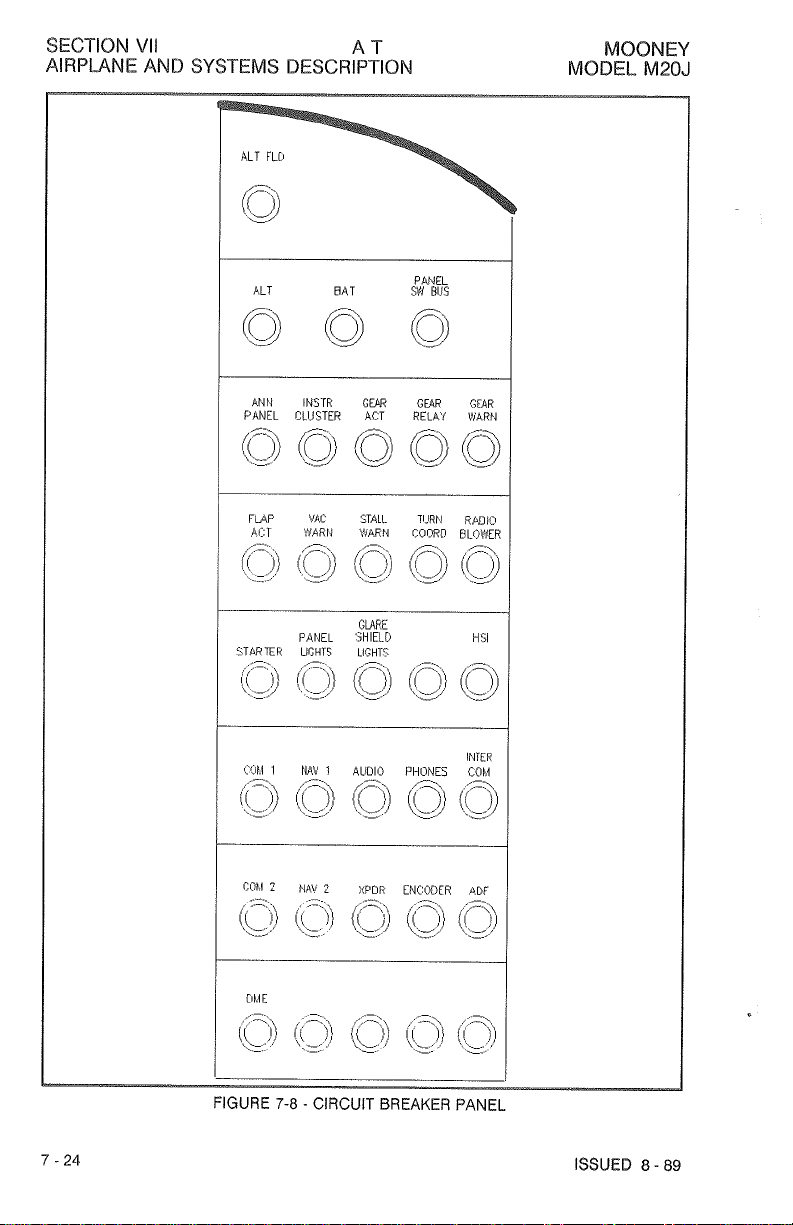
The main circuit breaker panel is in the extreme right panel. Figure
the main circuit breaiter panel with its push-pull circuit
circuit breakers are at the bottorn of the flight panel.
The alternator push-pull circuit brealter on the main breaker panel furnishes an
srnergoncy vverioad break between alternator and the main buss. Since the alternator is incapable of output in excess of the circuit brealter capacity, a tripped
breaker
cut
diminishing output with master switch
The alternator f~eld has a push-pull circuit breaker to furnish an emergency break in
the alternator field excitation circuit in the event of alternator or voltage regulator
malfunction. If regulator output voltage exceeds limits, the red voltage warning light
illuminates steadily.
Turnin off radio master switch and then turning master switch
reset
overvoltage light comes on again, pulling out alternator-field circuit breaker cuts
alternator out of the power circuit.
electrical power; therefore, ail electrical equipment not essential for flight
turned off and the flight terminated as soon as practical to correct the malfunction.
nsmmally indicates a fault within the alternator. Since the alternator is then
out of the power circuit, the storage battery supplies electrical power in steadily
tfe voltage regulator The overvoltage annunciator iight should remain out. If
&
BAmERY
on the ammeter; a discharged battery will be indi-
Ieve A voltage warning iight illuminates steadily when voltage
"
CAUTION
NPYNNR)NN
with
an
ex$ernel power source should
depleted.
alternator
BREAKER
I%
will not accept the high charge
and
eledrieal failure
PANEL
(SEE
FIGURE
ON.
low.
"
not
7-8)
be done while
may
brealters. A11 rocker switch-
rate
result.
OFF
Once again the battery is the only source of
14
the
baa$ery
from the
7-8
illustrates
and
ON,
should be
Volt,
will
I
-
------
I
MOTE
I
REV.
------
A3
-
90
may
vary
depending on installed
A
test switch and dim
ISSUED
The
circuit breakers installed in the panel
ANNUNCIATOR
The landing gear lights, low fuel lights, voltage light, vacuum warning light and
starter engaged light are grouped in the annunciator panel.
switch, are also found in the panel and each of the lights and switches are dis-
cussed elsewhere in this section.
7
-
22
equipment per customer order.
PANEL
8
-
89

MOBNEY
MODEL
M28J
AT
AIRPLANE
AND
SYSTEMS
SECTION
VII
DESCRIPTION
ISSUED
BmST
AIS
YO-ELEC
FIGURE
8
-
89
3-7
A
I
-
ELECTRICAL
REV.
B
SCHEMATIC
1-92
SECTION VII AT
AIRPWNE AND SYSTEMS DESCRIPTION
MOONEY
MODEL M20J


 Loading...