

MOONEY
OPERATORS
MANUAL
MODEL SERIAL NUMBERS
M2O
F
22-1306
&
ON
OCTOBER 1975
ISSUE
MOONEY AIRCRAFT
CORPORATION
KERRVILLE,
TEXAS
78028
MANUAL NUMBER 191O

ONEY
OPERATORS
MANUAL
O
OM
NEY
WARNING:
Up
to 2000
feet
of altitude
may
be lost in a
one-turn
spin and
recovery;
therefore
stallsatlow
altitude are
extremely
critical.
On
entering a
spin, the
aircraft will
roll,
very
much
like
a
barrel roll.
The
wings
willbenear
vertical at
EXECL/77//
VE
about the first quarter
turn of the spin. At
about the
half turn
point, the
wings are
approaching
level
but,
now, the nose
will
be
very
low--approaching vertical.
After
one
full turn has
been
completed,
the nose
will
come
up somewhat,
but
will remain
well
below the
horizon. The rate
of rotation during the
first portion
of the spin is
quite
rapid
and occupants of
the
aircraft
OPERATORS
MANUAL
šÏii.isbecob
esn eho
O
nuoe
orn
e
pointing
mo¡;p
nearly
toward
the
ground
than the
hori-
zon,
as
the airplane
revolves
and descends. As
the
spin progresses, it
may
enter
into what
is
referred
MODEL SERIAL NUMBERS
to as
a
flat
spin. When
the
spin becomes
flat,
the
M2O
F
22-1306
&
ON
aircraft nose comes
up
and remains more on the
hori-
zon,
with
possibly some shallow up and down
oscillation.
The rateofdescent and
rate of
rotation
both
become
slower.
An
air'craft inaflat spin
becomes stabilized
into
autorotation
and
once in
this
condition,
the
controls
become ineffective and
recovery
is
very
difficult or may
notbepossible.
In
complying with
the
FAA Regulation
for Normal
Cate-
gory
aircraft,
it
has been
demonstrated
that the
air-
plane will recover after
delayed
stall
recovery up
to
OCTOBER 1975
ISSUE
and
including
one-turn
spins.
This
one-turn
"margin
of
safety" is
designed to
pro-
MOONEY
AIRCRAFT CORPORATION
vide adequate
controllability
when
recovery from
a stall
is
delayed.
The
one-turn
"margin of
safety"
is
jeopar-
KERRV
I LL E,
TEX A S
78028
dized
if'the
airplane
is
not
recovered when the
first
evidence of
a
stall
is
detected.
MANUAL
NUMBER
1219
3-19
ONEY
PERATORS
MANUAL
POSITIVE
CONTROL
Positive
Control
will
hold
an
approximate
heading
over
a
period
of
tifne; however, it
will
not hold
an
exact
heading
without the
installation
ofamagnetic
heading
lock.
To check for
a
P. C. malfunction
while
in flight,_
first establish
a
moderate
bank; then,
release the controls to
see
if the
aircraft
will
return
to
straight
wings-level
flight as
indicated by
the
arti-
ficial
horizon.
Repeat the procedure with a turn
in
the opposite
direction.
Sluggish,
erratic,
or
in-
complete
bank
recovery warns
of a
malfunction
in the
P.
C.
system.
WARNING:
Thoroughly
familiarize yourself
with the flight characteristics of
the
aircraft
with
Positive
Control
inoperative. This
can
be done by simply holding
down the cutoff
button while
making
turns
and maneuvers.
Check the
P. C.
system frequently
during
each
flight
to insure
that
it is
functioning
properly,
particularly when IFR or
marginal weather
may
be
encountered.
In the eventofa complete engine
power
loss,
P. C.
will
continue to operate as
long
as the propeller is
windmilling
at 1000
RPM
or
more.
Loss
of
vacuum
will
automatically
make
the
P.
C. system
inoperative.
However,
the turn coordinator will
continue
to
oper-
ate on electrical power. The turn
coordinator
can
be
used
as a
flight
reference
if other gyro
instru-
ments become
inoperative.
3-20
ONEY
OPERATORS
MANUAL
ONEY
OPERATORS
MANUAL
FUEL
MANAGEMENT
LOG
OF PAGES
Proper fuel management
during flight
will
help
main-
tain lateral
trim and
will also
serve asafuel quantity
ONLY
the pages
listed
herein are applicable
check. After takeoff with
both
tanks
full,
use
fuel
to Model
M20F,Serial
Numbers
from
one
tank for one
hour;
then,
switch to the
other
tank
and
note the time.
Use
all the
fuel from the
sec-
Page
Date
SECTION
III
ond tank.
The
remaining fuel
endurance
in the
first
Title
10/20/75
Page
Date
tank can
be
calculated
from
the time it took to
deplete
i
. . . .
. . .
. . .
10/20/75
3-1
10/20/75
the
second
tank,
less one
hour.
You
must remember,
ii
...
. . .
. . . . .
10/20/75
3-2
. .
. .
...
10/20/75
however,
that this
endurance
calculating
procedure
can
iii . . .
. . .
. ... .
10/20/75
3-4
.
. ... .
. ...
10/20/75
be
relied
upon
only
if power
and mixture remain the
iv
. . .
. . .
. . . . .
10/20/75
3-5
. . ...
. ... .
10/20/75
same
and
an allowance
is
made
for the extra
fuel
used
3-6
.
. . . . . . .
. .
10/20/75
during
climb. For
estimation purposes,
consider fuel
3-7
. . . . . .
. . . .
10/20/75
consumption
during a
full-power climbtobe
40
percent
SECTION
I
• • • • • •
•••
higher
than
that
of
best-power
cruise,
and50percent
Page Date
3-10
. . . ...
.
10/20/75
higher than
that
of best-economy
cruise.
3-11..........10/20/75
1-1
. .
. . .
. . . . .
10/20/75
3-12
. . . . . ...
. . 10/20/75
CAUTION:
Do not
allow the
enginetolose
power
11-2
. .
. . .
. . . .
.
1 2200
3-13
.
. . . .
. .
.
.
.
10/20/75
or quit
before
switching
friel tanks.Ifa
tank
1-4
. .
. .
. . . . .
10/20/75
3-1
.
. . .
. . . ...
2
runs
dry and the
engine
quits,
retard
the
throttle
1-5
. .
. . .
. . . . . 10/20/75
3-16
10/20/75
before restarting.
Restarting
with
an
advanced
1-6
. .
. . .
. . .. . . 10/20/75
3-17
. . . .
. . . . .
10/20/75
throttle
may
cause engine overspeeding that can
3-18
. . .
. . .
...
.
10/20/75
lead
to
mechanical malfunction.
SECTION II
3-19
. . .
. .
.·
.,.
. .
10/20/75
3-20...........10/20/75
Page
Date
3-21
.
.
. . . . . .
.
.
10/20/75
INFLIGHT
RESTARTING
3-22..........10/20/75
2-1
. .
. . .
.
. . . .
10/20/75
3-23
10/20/75
2-2
.
.
. . .
. .
. . .
10/20/75
3-24
. . .
. .
10/20/75
1.
Propeller--HIGH
RPM.
2-3
..........10/20/75
3-25..........10/20/75
2-4
... .
.
. .
. . .
10/20/75
3-26
.
. . . ..... .
10/20/75 2.
Fuel
Selector--Fuller
tank.
2-5
..........10/20/75
2-6
. .
. . .
.
. . . .
10/20/75
SECT
ION
IV
3. Mixture
Control--IDLE
CUTOFF.
2-7
. .
. . .
.
. . . .
10/20/75
(FAA APPROVED)
2-8
..........10/20/75
2-9
... . .
.
. . .
.
10/20/75
Page Date
4.
Boost
Pump--ON.
2-10..........10/20/75
4-1
..........10/20/75
2-11
. .
. .
.
. . . . .
10/20/75
4-2
. . . . . . . ...
10/20/75
5.
Throttle--OPEN
1/4 travel.
2-12..........10/20/75
4-3
..........10/20/75
2-13..........10/20/75
4-4
..........10/20/75
2-14..........10/20/75
4-5
..........10/20/75
2-15..........10/20/75
4-6
..........10/20/75
2-16..........10/20/75
4-7
..........10/20/75
2-17..........10/20/75
4-8
..........10/20/75
2-18
... . .
.
. . . .
10/20/75
4-9
. ... . . . ...
10/20/75
3-21
4-10..........10/20/75
ONEY
OPERATORS
MANUAL
OONEY
OPERATORS
MANUAL
-
6. Ignition
Switch--BOTH.
LOG OF PAGES (CONT.)
7. Mixture
Control--Move
slowly
and smoothly
SECTION
V
SECTION
Vil
to
FULL
RICH.
(FAA
APPROVED)
Page
Date
Page
Date
8.
Re-establish
cruise
power
and
RPM,
then
lean
5-1
· · ·
·
...
.
. .
10/20/75
7-1
. .
.
.
. . .
. .
.
10/20/75
mixture.
5-2
•
• •
• ·
· ·
· ·
·
10/20/75
7-2
.
... . . ... .
10/20/75
5-3
•
• •
• •
• ·
·
· ·
10/20/75 7-3
.
... ... . . .
10/20/75
LETDOWN
5-4
• • •
· ·
·
· ·
·
·
10/20/75
7-4
. ..... ... .
10/20/75
7-5
. . . . . . ... .
10/20/75
Plan your letdown well
in
advance of
estimated
landing
7-6
... . . . . . . .
10/20/75
time.
Generally,
a
power-on
descent
is most
desir- SECTION VI
7-7
. ... . . .
. .
.
10/20/75
able. A gradual
rate
of
descent
at
cruising
speed
per¯
Pa
e
D
7-8
. . . .
. . . . .
.
10/20/75
mits
power
settings sufficiently
high to
maintain
proper
9
ate
7-9
. . ... . . . .
.
10/20/75
engine
temperatures and
to prevent
spark
plug
fouling.
6-1
. .
.
. . . . .
. .
10/20/75
7-10
. . . . . .
. .
. .
10/20/75
Sudden
power reductions at
higher airspeeds
can
damage
6-2
.
. .
. .
. ... . .
10/20/75
7-11
. . . . . .
. . .
.
10/20/75
the
engine by
causing
it to cool
too
rapidly.
6-3
.
.
. . . . . .
.
.
10/20/75
7-12
... . . . . . . .
10/20/75
6-4
. .
. . . . . .
. .
10/20/75
Establish
a gradual
letdown by
reducing
power below
6
100/2200
cruise while
maintaining
cruise airspeed
throughout 6-7
. ...
.
.
. .
. .
10/20/75
the
descent.
Monitor
cylinder
head and
oil
tempera-
6-8
. .
. .
. . . . .
.
10/20/75
tures throughout
descent to guard against over
cooling.
6-9
. .
. . .
.
. .
. .
10/20/75
Oil in the oil cooler
can congeal
very
rapidly
after a
6-10
. . . .
. . . . .
.
10/20/75
power
reduction
when
flying in
cold
weather.
6-11
.
.
. . . . . .
. .
10/20/75
6-12
.
. . .
. . . . .
. 10/20/75
6-13
.
. . . .
.
. .
. . 10/20/75
CAUTION: Do
not
lower
gear above
120 MPH
6-14
.
. .
. . . . . .
.
10/20/75
(104
Knots)
IAS.
Do
not lower
flaps above
125 MPH (109
Knots)
IAS.
Do not
exceed
125
MPH
(109
Knots)
IAS
with
the flaps
down
or
120 MPH (104
Knots)
IAS with
gear
down.
BEFORE-LANDING
CHECK
1. Seat
Belts--FASTENED.
2. Fuel
Selector
Handle--SET
for
fuller
tank.
3. Electric Fuel
Pump--ON.
4.
Mixture
Control--FULL
RICH.
5. Ram
Air
Control--CLOSED;
warning
light
off.
3-22
ONE_Y
OPERATORS
MANUAL
GENERAL
DESCRIPTION
. .
. .
. . .
. . . SECTION
6.
Airspeed--REDUCE
to 120 MPH (104
Knots).
7.
Propeller--FULL
INCREASE.
8.
Landing
Gear--DOWN
and
LOCKED;
green
an-
nunciator
light
on.
SYSTEMS
OPERATIONS
. . .
. . . . ...
.
SECTION
9.
Flaps--As
required.
10.
Trim--As
required.
NORMAL
PROCEDURES
.
. . . . . . .
. . .
SECTION
O i r
ly,
you
should
complete
the
Before-Landing
Check on the downwind
leg.
To
allow forasafe
mar-
gin
above stall speed throughout
approach,
hold
air-
speed above
90
MPH
(78
Knots) until the flaps are
lowered.
Degree of
flap
deflection needed will
vary
according to
landing
conditions, but for most landings you
LIMITATIONS
...
. . . . ... . . ...
. . .
SECTION
should lower
flaps
to
TAKEOFF
position just
prior to
turning
on to
base
leg.
Extend
flaps as required on
final approach to adjust
for
variations
in wind, glide
angle,
and other variables.
WARNING:
The stall
warning
horn and
the
landing
gear
warning
horn
are inoperative
when
EMERGENCY
PROCEDURES
... . .
. . .
SECTION
the
master
switch is in the
OFF
position.
On
final,
trim the aircraft to
fly
hands-off
at
an
approach speed of
about 80
MPH
(70
Knots). As
you
cross the
runway
end
markers,
reduce
power
to idle.
Slow the rate of descent by
increasing
back pressure
PERFORMANCE
. . .
.
.
.
. ...
. ... .
.
SECTION
on the control wheel
until the aircraft
settles on the
runwayina
slightly
nose-high
attitude. (When high,
gusty winds prevail, or when
landing
crosswind,
approach
at a
higher
airspeed.)
Slowly
relax
back
pressure
and gently
lower
the
nose
wheel to the
run-
way
after main gear contact
so
the
nose
gear
steering
system
can be
used to
help control
landing
rollout
SERVICING....................SECTION
direction.
3-23
ONEY
OPERATORS MANUAL
ggg
. . .
.
.
.
. . .
.
. . .
.
.
CAUTION: Do
not
allow the
aircraft to
touch
down
in
a
nose-low
attitude
or
at
too high
an
This
manual
is
issued
as your operating
guide
for
the
airspeed.
Either
of
these conditions
will allow
Mooney
Executive.
It
is important
that
you--regardless
the
nose
wheel
to contact
the
runway
first,
of your previous
experience--carefully
read the
hand-
which
may
cause the
aircraft
to
porpoise
and
book
from cover to cover
and review it
frequently.
damage
the
gear.
Unless
a
short
roll
is necessary,
you
should
allow
the
IMPORTANT:
THIS
MANUAL
CONTAINS
aircraft to
slow
to a
moderate
taxi
speed
before
ap-
Federal
Aviation
Adininistration
APPROVED
plying
brakes.
After
leaving
the
runway,
turn
off
the
LIMITATIONS AND
MUST BE CARRIED
IN
electric fuel
pump,
open
the
cowl
flaps,
retract
the
THE
AIRCRAFT AT
ALI TIMES.
flaps,
and
reset
the trim
to
TAKEOFF. Hold taxi
power
setting
between
1000 and
1200 RPM
to permit
All
information and
illustrations in
this manual are
uniform
engine cooling•
based
on the latest product
information
available at
the time
of
publication
approval.
The right
is reserved
Execute
short-field
landings with
partial power and
to
make
changes at
any
time without
notice.
Every
full
flapsonfinal
approach.
Reduce
power
to idle
effort
has
been made to
present the material
in
a
clear
during
flareout,
and
touch down
first
on
the
main
and
convenient
manner
to
enable
you
to use
the
manual
wheels.
before
allowing
the nose
wheel
to
make
con-
tact.
You
may
apply
brakes
as soon
as all
wheels
as
a ready
reference.
Your
cooperation
in reporting
are
firmly
on the
ground.
For maximum
braking
presentation
and content recommendations
is
solicited.
effect,
raise the
flaps
and
apply
back pressure on
the
control wheel
as you
apply
brakes. Do not skid
the main wheels, as doing
so
will reduce
braking
effectiveness and
damage the tires.
AFTER
LANDING
1. Wing
Flaps--RETRACT.
2. Electrical
Fuel
Pump--OFF.
3.
Cowl
Flaps--OPEN.
TAX1
CHECK
1.
Throttle--1000
to 1200
RPM.
2.
Lighting--As
required.
3.
Stabilizer
Trim--TAKEOFF.
3-24
i i
.
. . . .
. . . .
. . . .
. .
ONEY
PERATORS
MANUAL
Mooney
warrants each Aircraft
(which
includes
SHUTDOWN CHECK
its accessories and equipment)
sold
hereunder,
to be
free
from
defects in
materialand
workman-
1.
Throttle--IDLE
at
1000 to
1200 RPM until
cy-
ship under normal
use
and
service
when operated
linder
head
temperature
starts to
drop.
in
accordance
with
Mooney's operating
instruc-
tions
during the
period
of
six
(6)
months
following
2.
Cowl
Flaps--OPEN.
delivery
of
the
Aircraft
to the original retail
pur-
chaser
or the
first user
or
during
the period of
3.
Radios--OFF.
one
(1)
year
foÈowing
the
date
of issue of
the
ori-
4.
Electrical
Switches--OFF.
ginal
airworthiness certificate
for
the
Aircraft,
whichever
period
first
terminates.
Mooney
does
5.
Mixture
Control--IDLE
CUTOFF.
not
make
any
warranties with
respect
toequipment
and accessories
not
manufactured
by
Mooney
but
6.
Throttle--RETARD
as engine
stops
firing.
Mooney assigns to any
owner of such Aircraft (to
the extent same
may
be
assignable)
any
warranties
7.
Ignition
Switch--OFF
when
propeller
stops.
Mooney has received from the manufacturers of
such equipment
and accessories
and
will,
on
re-
8.
Parking
Brake--Set
(for
short-term
parking).
quest, provide
and
execute
such
instruments as may
be
reasonably
required to evidence
such
assignment.
9.
Trim--TAKEOFF.
Mooney's obligation under
this
warranty
is
limited
to
repairing or replacing, at
Mooney's
option, any
10.
Flaps--RETRACTED.
part or
parts which within
the applicable
warranty
11.
Master
Switch--OFF.
period
set forth
above,
shall
be
returned,
trans-
portation charges prepaid, to
Mooney's
plant
in
12. Control
Wheel--LOCK
with seat
belt.
Kerrville,
Texas
or to such
other
location
desig-
nated
by Mooney,
and which
upon examination,
shall
13.
Overhead Air
Scoop--CLOSED.
disclose to
Mooney's satisfaction
that
such part is
defective.
A
new
warranty
period is not established
14.
Wheel
Chocks
and
Tiedown--As
required.
for parts
replaced hereunder.
Parts
replaced
here-
under
are
warranted for
the
remainder
of the original
warranty
period
applicable
to Aircraft
sold
hereunder.
The repair or
replacement
of
defective
parts under
this
warranty
shall be made by
Mooney
without
charge
for
the parts,
or labor
for
removal,
installation
and/
or
actual repair of defective
parts.
This
warranty
does not apply
to
Air craft,
equipment,
accessories,
or other parts
manufactured or sold
by
i i
i
3-25
Mooney
which have
been subject to
misuse,
negligence,
accident
or
improper
installation,
or
which
have
been
repaired or
altered outside of
Mooney's
plant in
a
way
which,
in
the
opinion
of
Mooney,
adversely
affects its
performance or reliability.
Further, this
warranty
does not
include
normal
maintenance
ser-
vices
(such
as engine
tune-up;
cleaning,
control
rig-
ging,
brake
and other mechanical
adjustments,
maintenance
inspections,
etc.)
and the
replacement
of service
items (such as
sparksplugs,
brake
linings,
filters, hoses, belts, tires, etc.)
made
in connection
with such
services or required
as
maintenance,
nor
to normal
deterioration of soft
trim
and
appearance
items
(such
as,
paint,
upholstery,
rubber-like
items,
etc.)dueto
wear and
exposure.
This
warranty
shall
extend
to any owner
(hereafter
"Owner")
of the
Aircraft
making
claim within the
specified
warranty
period.
THIS WARRANTYBYMOONEY
IS MADE EXPRESSLY IN
LIEU OF ANY OTHER WARRANTIES
EXPRESSED
OR
IM-
PLIED IN FACT OR BY LAW, INCLUDING ANY IMPLIED
WARRANTY
OF MERCHANTABILITY OR FITNESS FOR
A
PARTICULAR
PURPOSE,
AND IS IN LIEU OF ANY
OTHER
OBLIGATION OR
LI.ABILITY
ON THE PART OF MOONEY
TO ANYONE OF
ANY
NATURE WHATSOEVER BY REASON
OF
THE
MANUFACTUREAND/OR
THE
SALE AND/OR THE USE
OF SUCH
AIRCRAFT.
MOONEY SHALL IN
NO EVENT BE
LIABLE TO ANY OWNER OR TO ANY
OTHER
PARTY
OR
PARTIES FOR SPECIAL, INCIDENTAL OR
CONSEQUEN-
TIAL LOSS OR DAMAGES 08 FOR ANY
OTHER
LOSS
OR
DAMAGETOPROPERTY AND/OR INJURY OR DEATH
TO
PERSONS
OTHER THAN FOR
THE
PROPERTY
DAMAGETO
SUBJECT AIRCRAFT
PROXIMATELY
RESULTING FROM ANY
BREACH BY MOONEYOFTHE AFORESTATED WARRANTY,
MOONEY
NEITHER ASSUMES
.NOR
AUTHORIZES BUYER OF
ANYCNE ELSE
TO ASSUME FORITANY
OBLI.GATION OR
LIABILITY IN
CONNECTION WITH
THE AIRCRAFT
SUB-
JECT HEREOF,
OTHER THAN
THOSE EXPRESSLY
SET.0UT
HEREIN. NO BILL
OF
SALE OR TRANSFER OF
TITLE
TO THIS AIRCRAFT SHALL NULLIFY
THE
PROVISIONS
HEREOF.
iv
SECTION
I.
GENERAL DESCRIPTION
DESIGN
FEATURES
SECTIONS
IV.
&
V.
AIRFRAME...........................1-2
POWERPLANT........................1-2
FAA
APPROVED
FLIGHTCONTROLS.....................1-3
AIRPLANEFLIGHTMANUAL
LANDINGGEAR
.......................1-3
SPECIFICATIONS
OUTUNE
POWERPLANT........................1-3
PROPELLER
.........................1-4
SECTION
IV.
LANDINGGEAR
.......................1-4
AIRCRAFT
LIMITATIONS
FUEL&OIL..........................1-5
AND
OPERATIONS
WEIGHT&LOADING....................1-5
BAGGAGE
COMPARTMENT
. . . ... ... . . . . . .
1-5
MOONEY MODEL
M20F
EXECUTIVE
MOONEY
AIRCRAFT
CORPORATION
SERIAL
NO.:
REGISTRATION NO.:
This Manual Must Be Kept Onboard
The
Airplane At All
Times
APPROVED BY:
CHIEF,ENGINEERING
&
MANUFACTURING BRANCH,
SOUTHWEST
REGION,FEDERAL
AVIATION ADMINISTRATION
DATE:
1-1 4-1
FAA
APPROVED
MOONEY
M20F
1
_Y
10/20/75
MOONE
OPERATORSMANUAL
LOG OF
REVISIONS
.
DESIGN FEATURES
LETTER
PAGE
DATE
APPROVED
The
MOONEY EXECUTIVE isalow-wing
four-place
air-
craft
with
a
retractable gear. A four-cylinder
engine
powers
the
aircraft for
economical,
high-performance
flight.
Li-
censing
under Federal Aviation Administration regulations
assures
that
your
Mooney
meets
the
requirements
of Normal
Category
aircraft.
AIRFRAME
The
airframe has a
welded,
tubular-steel
cabin structure
enclosed in
sheet-aluminum
skins.
Stressed skins
rivet to
main and
auxiliary
spars in the wing,
stabilizer,
and
ver-
tical
fin.
The
laminar-flow
wing has full
wrap-around
skins
with
flush
riveting
over
the
forward
top two
thirds
of the
wing area.
For pitch trim
control,
the empennage
pivots
on the aft
fuse-
lage.
A
torque-tube-driven
jack
screw, bolted to
the
rear
tailcone
bulkhead,
sets
the
stabilizer angle.
The
forward-opening
cabin door
provides
access to both
front
and rear
seats.
The baggage
compartment door
is
above the
wing trailing
edge to enable baggage
loading
from
the ground.
POWER
PLANT
The
power
plant is a
four-cylinder fuel-injected engine
that
develops 200
horsepower.
A
60-ampere
12-volt
alternator
supplies
ample electrical power
for
all standard and optional
equipment
at all
engine speeds
from warmup to flight
power
settings.
The hydraulic
propeller governor,
using
oil
pressure
for
increasing
blade
pitch to control engjne
speed, regulates
the controllable-pitch constant-speed propeller. Spring
and blade
aerodynamic forces decrease
blade pitch.
4-2 1-2
ONEY
PERATORS
MANUAL
FAA
APPROVED
MOQNEY
M20F
10/20/75
FLIGHT CONTROLS
OPERATING LIMITATIONS
Conventional dual controls link to
the control surfaces
through
push-pulÎ
tubes.
The
copilot's
rudder
pedals
The
following
limitations
must
be
observed
in the
are
removable.
operation of this airplane:
The
Mooney
Positive
Control
(P.
C.)
system is
optional
equipment.
P.
C.
isalateral
stability
augmentation
AIRSPEED
LIMITATIONS
system
that
provides
a
high
degree of
roll
and
yaw
sta-
bility,
thereby
enhancing
the inherent
wings-level
flight
Never
Exceed Speed. .
200 MPH (174
Knots)
CAS
characteristics of the aircraft.
The system works full
time
from takeoff
through
landing
but can be
easily
Max
Man. Speed
...
135 MPH (117
Knots)
CAS
deactivated
or
overpowered for flight maneuvers. P. C.
allows
you,
the pilot,
to
devote more time to navigation,
MC
ui ng
S
eaed
...
175
MPH
(152
Knots)
CAS
traffic
surveillance,
and communications.
Max Gear
Operating
LANDING GEAR
Speed
... .
. . .
120
MPH (104
Knots) CAS
Max
Gear
Extended
The
tricycle
landing
gear allows maximum
taxi vision
Speed .
. . . ...
120 MPH (104
Knots) CAS
and
ground maneuvering.
Hydraulic disc brakes and
a
steerable
nose wheel aid
in positive directional
control
Max
Flap
Operating
during
taxiing
and crosswind
landings.
Speed .
.
. .
. . .
125
MPH (109
Knots)
CAS
The
landing
gear is
electrically
retracted. A
gear
warning
horn
along
with
a
green
"geardown" light help
AIRSPEED
INSTRUMENT MARKINGS
prevent
inadvertent
gear-up
landings.
The
retraction
system
incorporates
a
squat switch
that
prevents gear
Radial Red Line
. .
. 200 MPH (174
Knots)
CAS
retraction
when the
landing
gear
mechanism
is
com-
(Denotes never exceed speed
which is
the
maxi-
pressed
by
the weight of
the
aircraft. An
emergency
mum safe
airspeed)
gear
extension system is
provided.
Yellow Arc
.
.175 to
200
MPH
(152to174 Knots)
CAS
(Denotes
range
of
speeds
in
which
operations
should be
conducted
with
caution
and
only
in
smooth
air)
SPEClFICATIONS
OUTLINE
Green Arc. .
69 to
175 MPH
(60to 152
Knots)
CAS
(Denotes normal
operating speed
range)
POWER
PLANT
White Arc . . 64
to 125
MPH (56 to 109
Knots)
CAS
(Denotes speed
range in
which
flaps
may
be
TYPE:
Four-cylinder,
air
cooled,
horizontally opposed,
safely lowered)
1-3
4-3
FAA
APPROVED
MOONEY
M20F
10/20/75
DONEY
OPERATORSMANUAL
POWER
PLANT
and
fuel-injected
engine with
a
wet-sump
lubricating
Engine
. . .
.
. .
Lycoming
Model
IO-360-A1A
system.
Model (Lycoming)
. .
. . . . . .
IO-360-A1A
Engine
limits
for
all
Rated
Horsepower
@
2700
RPM
.
. .
200 BHP
operations
.
. .
.
200
BHP,
2700 RPM.
Bore . . .
.
. . . . . . ... .
.
5. 125 IN.
Stroke
..............4.375IN.
Fuel .
. .
. .
.
. 100/130 octane
aviation
Displacement
. . .
.
. . . . . 361. O
CU.
IN.
gasolme.
Compression
Ratio .
... . .
.
. . 8.7:1
Fuel
Injector,
Bendix
.
. ... .
RSA-5-ADI
Propeller
.
.
...
Hartzell
Constant Speed
Magnetos, Scintilla .
.
. .
S4LN-200
Series
Hub
HC-C2YK-1BF
Blade
F7666A-2
Pitch
setting
at
30-inch
station:
High
29°+
2°
•
PROPELLER
Low
14°
+
00
.
¯
TYPE:
Constant-speed,
hydraulically
controlled
pro-
Cowl
Flaps
.
.
. .
Open
for
takeoff, climb, and
peller
with
a
single-acting
governor.
ground
operations.
Open as
re-
quired
for
continuous
opera-
Model
(Hartzell) .
. .
.
HC-C2YK-1BF/F7666A-2
tion
to maintain
cylinder head
Diameter
.
.
. . . .
... . .
. . .
74
IN.
temperature
below
4000F.
Blade Angle
@
30 IN.
STA):
(Do not
open
above 150
MPH
-
Low
. .
. . ...
. ...
.
. . .
14°+0°
130
Knots).
High
.
.
. . . .
. .
. .
.
.
. .
290¯20
POWER
PLANT INSTRUMENTS
LANDING
GEAR
Tachometer
TYPE:
Electrically retracted tricycle gear
with
rubber
Radial
Red Line (Rated)
. ...
. 2700 RPM
shock
dises,
steerable
nose
wheel,
and hydraulic
disc
Green
Arc--Narrow
(Rated
opera-
brakes.
ting
range)
. .
.
...
. .
2500-2700
RPM
Green
Arc--Wide
(Recommended
Wheel
Base .
.
. . . .
.
. 5 FT
11-9/16
IN.
operating
range)
. .
.
. .
2350-2500
RPM
Wheel
Tread
.
... .
. . . .
9
FT
3/4
IN.
Red
Arc--Wide
(No
continuous operation
Tire Size:
in this
range)
... .
.
. .
2100-2350
RPM
Nose
.
. .
.
. .
. .
.
. .
.
. .
5.
00 x
5
Main...............
6.00x6
Tire
Pressure:
Nose...............
49PSI
Main...............
30PSI
4-4
1·4
ONEY
OPERATORS
MANUAL
FAA APPROVED
MOONEY
M20F
¯¯¯
10/20/75
Cylinder
Head
Temperature
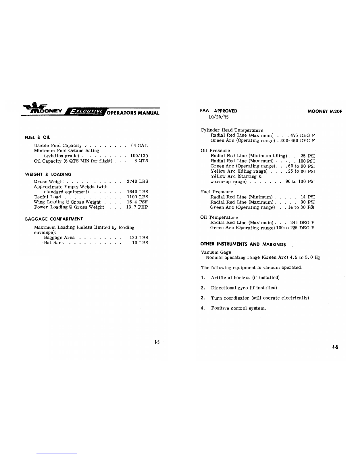
FUEL &
OIL
Radial
Red Line (Maximum) . ..475 DEG
F
Green
Arc (Operating range) .
300-450
DEG F
Usable Fuel
Capacity
.
. . . . .
.
. . 64 GAL
Minimum
Fuel Octane
Rating
Oil Pressure
(aviation
grade) .
. .
. . .
. . . 100/130 Radial
Red
Line (Minimum
idling)
.
.
25
PSI
Oil Capacity(6QTS MIN for flight) .
. .
8
QTS
Radial
Red
Line
(Maximuni)
. .
. . .
100 PSI
Green Arc (Operating
range).
. .
60 to
90 PSI
Yellow Arc
(Idling
range)
. .
. . 25
to
60
PSI
WEIGHT
& LOADING
Yellow
Arc
(Starting
&
Gross
Weight
. . . .
.
. . .
.
. . 2740
LBS
warm-up
range)
.
. . . . . . 90 to 100
PSI
Approximate
Empty
Weight (with
standard
equipment)
. .
. . .
. 1640 LBS Fuel Pressure
Useful
Load
. . . . . .
. . ... .
1100 LBS
Radial Red Line
(Minimum)
. . . . .
14 PSI
Wing Loading
@
Gross
Weight
... .
16.4 PSF
Radial Red Line
(Maximum) .
. . . . 30
PSI
Power
Loading @
Gross
Weight .
. .
13.
7
PHP
Green Arc (Operating
range)
.
.
14
to 30
PSI
BAGGAGE
COMPARTMENT
Oil
Temperature
Radial
Red Line (Maximuin)
. .
. 245 DEG
F
Maximum
Loading
(unless limited by
loading
Green
Arc (Operating
range)
100to
225 DEG
F
envelope):
Baggage
Area .
. . . .
. .
. .
120
LBS
Hat
Rack
.
. .
.
. .
... . .
10
LBS
OTHER
INSTRUMENTS
AND
MARKINGS
Vacuum
Gage
Normal operating
range
(Green Arc)
4.5 to
5.0
Hg
The following
equipment is
vacuum
operated:
1. Artificial horizon (if installed)
2.
Directional gyro
(if installed)
3. Turn
coordinator
(will
operate
electrically)
4. Positive control
system.
1-5
4-5
FAA
APPROVED
MOONEY
M20F
10/20/75
nŒY
OPERATORS
MANUAL
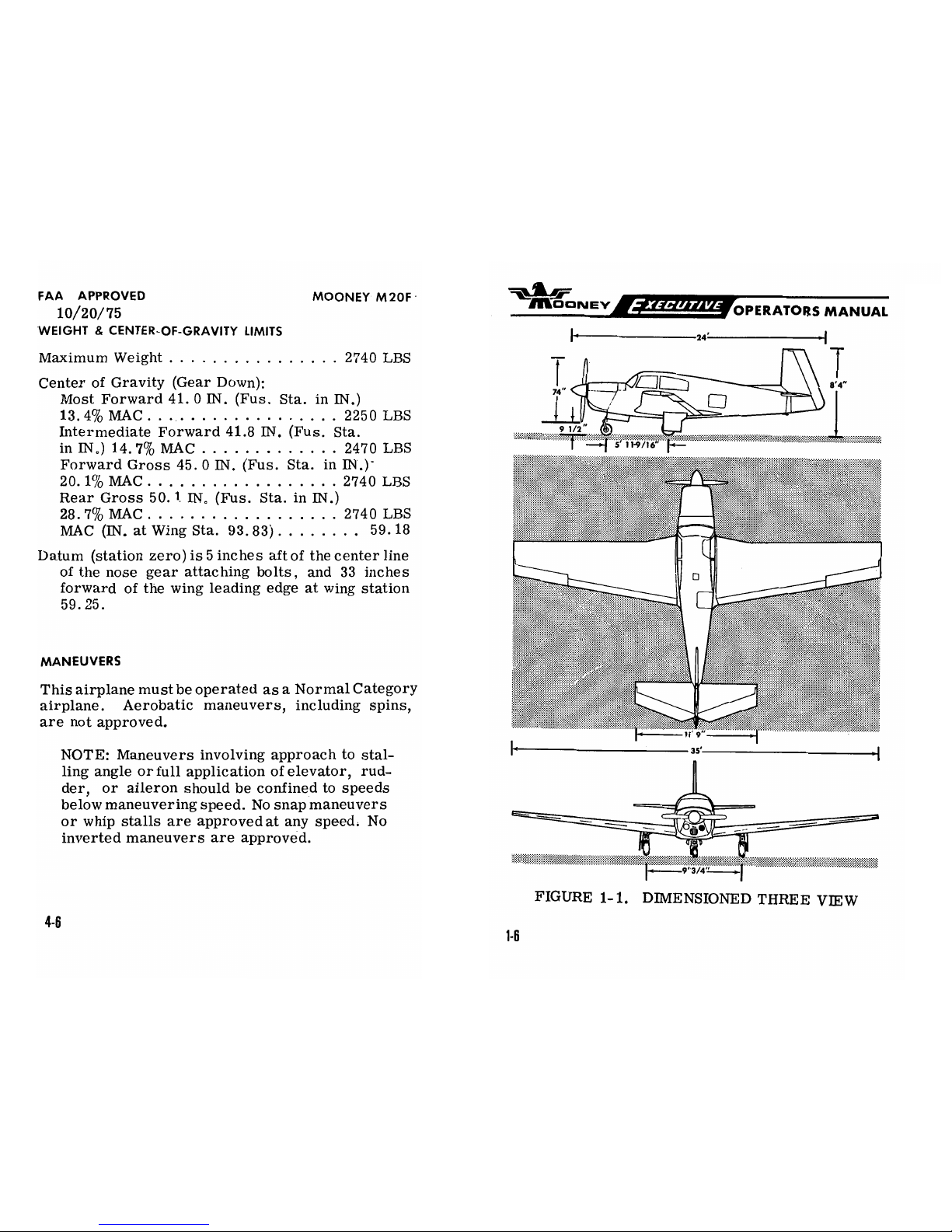
WEIGHT
&
CENTER-OF-GRAVITY
LIMITS
MaximumWeight................
2740LBS
Center
of
Gravity
(Gear
Down):
.-4-
Most Forward 41. O
IN. (Fus.
Sta. in
IN.)
13.4%MAC...................
2250LBS t
#
Intermediate Forward
41.8 IN. (Fus.
Sta.
1/2
inIN.)14.7%MAC.............
2470LBS
UN/16"
Forward
Gross
45. O
IN.
(Fus.
Sta. in
IN.)·
20.1%MAC..................2740LBS
Rear
Gross 50.
I
IN.
(Fus.
Sta.
in
IN.)
28.7%MAC.................. 2740LBS
MAC (IN.
at
Wing
Sta.
93.83). .
. .
. . .
.
59.18
Datum
(station
zero)
is
5
inches
aft
of the
center
line
of the
nose
gear
attaching
bolts,
and
33 inches
I
O
forward
of the wing
leading
edge at wing
station
59. 25.
MANEUVERS
This airplane
must
be
operated
as a
Normal
Category
airplane.
Aerobatic
maneuvers,
including
spins,
are not approved.
NOTE:
Maneuvers
involving
approach to
stal-
ling angle
or full
application
of
elevator,
rud-
der,
or
aileron should
be
confined to speeds
below maneuvering
speed. No
snap
maneuvers
or
whip stalls are
approved
at any
speed.
No
__.
inverted maneuvers
are approved.
9 3/4"
i
FIGURE
1-1.
DIMENSIONED
THREE
VlEW
4-6
1-6
FAA
APPROVED
MOONEY M20F
SECTION
11.
SYSTEMS
OPERATIONS
10/20/75
POWER
PLANT
FLIGHT LOAD
FACTORS
ENGINE
CONTROLS. . . . . . .
. . .
...
.
.
. . .
. .
2-4
Maximum
Positive
Load
Factor,
IGNITIONSYSTEM.....................2-5
FlapsUp
.........................3.8
FUELSYSTEM
.......................
2-6
Maximum Positive
Load
Factor,
OILSYSTEM...................······
2-6
FlapsDown
(330)
.......
..........
.. .2.0
ENGNE
COOLNG
. . . . ...
. . .
. .
... . . .
. .
.
2-7
Maximum
Negative Load
Factor
VACUUMSYSTEM.....................2-7
FlapsUp
...............'..........1.5
INSTRUMENTS
FLIGHT
INSTRUMENTS
. . .
. . . . .
. . .
. . .
. .
.
2-7
TYPES OF
OPERATION
FLIGHT
CONTROLS
Do
not
operate in known
icing conditions.
PRIMARY
FLIGHT
CONTROLS
. . .
. . . .
. . . . .
2-8
This is
a
Normal Category
aircraft
approved
for
POSITIVE
CONTROL . .
. . . .
. . . .
. . . . .
. . .
.
2-9
VFR/IFR,
day
or
night
operations,
provided
the
TRIM
CONTROLS . . .
. .
. . . . . . . . .
.
. .
. . .
.
2-10
following
instruments and equipment
are installed
WNG FLAP
CONTROLS . .
.
.
. . . . .
. . . . .
. . .
2-10
and
operating
properly.
LANDING GEAR
ELECTRIC GEAR RETRACTION SYSTEM
.
. .
. .
2-11
REQUIRED
EQUlPMENT
EMERGENCY
GEAR
EXTENSION SYSTEM
... . .
2-12
BRAKE &
STEEREG SYSTEMS
.
.
. . . . ... . . .
2-12
VISUAL
FLIGHT RULES
-
DAY
ELECTRICAL
POWER
Airspeed indicator
ALTERNATOR &
BATTERY.
. . . . . .
.
.
. .
. .
.
.
2-12
CIRCUIT
BREAKERS
.
.
. .
. .
.
. . ...
.
. .....
2-13
Altimeter
ANNUNCIATOR
LIGHTS
.
... .
. ...
.
. . . . . .
.
2-15
Magnetic
direction
indicator
(Mag compass)
INSTRUMENT&PLACARD
LIGHTS
. .
. .
. . . . .
2-16
Tachometer
CABIN
LIGHTING
. . . .
. . . . . . . . . . . .
. . . .
.
2-16
Manifold
pressure
gage
CABIN ENVIRONMENT
Oil pressure
gage
HEATNG&VENTILATNG
SYSTEMS
. . . . .
. . .
2-16
Oil temperature
gage
WNDSHIELD DEFROSTNG
SYSTEM
...
. .
.
. .
2-19
Cylinder
head temperature
gage
Fuel
quantity gage
for
each
tank
CABIN
Fuel pressure
gage
SEATS&SAFETY
BELTS
. . . . . . . . . . . . . . .
.
2-17
Landing
gear
position indicator
BAGGAGE&CARGOAREAS
..............
2-18

FAA0/
/7R5OVED MOONEY M20F
OPERATORS
MANUAL
Gear warning
horn
Acquiring aworking
knowledge of the
aircraft's controls
Stall
warning
system
Master switch
and equipment is one of your important
first
steps
in
de-
veloping a fully
efficient
operating
technique.
This
Systems
Battery
and alternator
. . Operations
section describes
location,
function,
and
oper-
Circuit breakers and
fuses
ation
of
systems' controls and
equipment.
It
is
advisable
Seat
belts
for
all
occupants
for
you, the
pilot,tofamiliarize
yourself
with
all
controls
Emergency
locator transmitter
and
systems
while
sitting
in
the pilot's
seat and
rehearsing
the systems
operations
and
flight
procedures
portions of
VISUAL FLIGHT RULES
---
NIGHT
this manual.
All
equipment
and
instruments specified
for
VFR
---
day
Position lights
Electric landing
light
(if
used
for hire)
Instrument
lights
e
ANntST
EonN
F IGHT
RULES
46
6
11 13
14
All
equipment and
instruments
specified for
VFR
---
night
Gyroscopic
rate-of-turn
indicator
Bank indicator
°
---
0 oooo
Sensitive
altimeter
adjustable for
barometric
pressure
Clock
with
sweep
second
hand
a
22
Artificial
horizon
Directional
gyro
Adequate
power source
for each gyro
instrument
Two-way
radio
communications
system
and
navi-
gational
equipment
appropriate
to
the
ground
faci-
lities to be used
NOTE: Caution
should
be exercised
when
in-
stalled
communications equipment interrupts
the
navigation signal during
transmissions.
FIGURE
2-1.
INSTRUMENT PANEL
4-8
2-2

FAA
APPROVED
MOONEY M20F
¯MOONEY
OPERATORS
MANUAL
10/20/75
1.
Clock
23. Quadrant Friction
Controi
PERFORMANCEINFORMATION
2. Airspeed Indicator
24.
Parking
Brake
Control
3. Artificial Horizon
.25.
Cabin
Vent
Control
Up
to
220-foot
altitude
loss
may
occur
during stalls
4. Altimeter 26.
Cabin
Heat
Control
at maximum weight.
5.
Engine
Cluster
Gage-
27. Microphone Jack
Fuel
Quantity,
28. Headset Jack
Oil
Temp,
29.
Trim
Control
Wheel
OPERATING
PROCEDURES
Oil
Pressure,
30. Fuel Tank
Selector
Valve
Cylinder
Head
(Located on Floor)
Temperature,
31.
Trim
and
Flap
Position
NORMAL
Ammeter
Indicator
6.
Landing
Gear
Switch
32.
Heater and Vent
Outlet
This
airplane
must
be operated
as
a Normal
Cate-
7.
Landing
Gear
33.
Ash
Tray
gory airplane in compliance
with the
operating
lim-
Position
Lights
34.
Aircraft Registration
itations
stated in the
form
of
placards,
markings,
8. Outside
Air
35.
Instrument
Panel
and manuals. No acrobatic
maneuvers,
including
Temperature Gage(Opt.)
Light
Controls
spins,
are approved.
9.
Magnetic
Compass
36.
Propeller
Governor
10. Pilots
Check
List
Control
Circuit
breakers
are located on
the right
hand side
11.
Annunciator
Lights
-
37
Throttle
of
the
co-pilot's
instrument
panel.
The
alter-
High and
Low
Voltage
nator
circuit
breaker is
on
the
circuit
breaker
panel.
"
38.
ELT
Remote
Switch
Ram
Air
Circuit breakers
are
push-pull
or
push-to-reset
type.
39.
Electrical
12.
Radio Panel
13. Vacuum
Gage
Circuit Breaker/Switches
Retract
flaps
after
landing.
14. Manifold Pressure
and
40.
RateofClimb
Indicator
Fuel Pressure
Gage
41.
Master
Switch
Turn
ram
air off
for
takeoff, landing,
or
any
15.
Exhaust Gas
Temp
42.
Directional
Gyro
time when operating
in dusty conditions.
16. Circuit
Breaker Panel
43.
Not
Used
17. Tachometer 44.
Turn Coordinator
All
warning
devices are inoperative when the master
18.
Cigar
Lighter
45.
Magneto/Starter
Switch
,
switch is off.
19. Ram
Air
Control
46.
Omni
Indicator
20. Cowl
Flap
Control
47.
Omni Indicator
Do
not
open
storm
window
above
150 MPH (130 Knots).
21. Flap Control Switch
48.
ADF Indicator
22. Mixture Control
49.
Radio Microphone
A horn
emitting a steady
tone
warns
of approaching
stall.
A
horn
emitting an
intermittent
tone warns
of
a
re-
tracted
landing
gear when
power
is
reduced
below
about
12 IN. Hg manifold pressure.
2-3
4-9

FAA
APPROVED
MOONEY
M20F
10/20/75
_N_
OPERATORS
MANUAL
The
PC
system cutoff switch in the left
hand
grip
of the
pilot's
control
wheel,
deactivates PC
when
squeezed.
POWER
PLANT
The
roll-trim
knob on the turn
coordinator provides
ENGINE
CONTROLS
a
command trim function. Rotation in
a
clockwise
direction trims
right;
counterclockwise
rotation trims
The
engine control
levers
are
centrally located,
between
left.
the
pilot and
co-pilot,
on the engine control
pedestal.
The
throttle
lever regulates
manifold pressure.
Pushing
the
To
preclude
fuel
starvation,
avoid extreme
sus-
lever
forward increases
the
setting;
pulling the lever
aft
tained
side
slips
toward the tank in
use
when
that
decreases
the
setting.
tank
contains less than
48
poundsoffuel.
The
propeller control
lever,
with
its
crowned
knob,
con-
trols
engine RPM through the propeller governor.
Push-
EMERGENCY
ing the
lever forward
increases engine RPM;
pulling
the
Emergency
procedures
are
contained in the
Emer-
lever aft
decreases the setting.
gency
Procedures
section
on
the
next
page.
The
mixture control
lever,
with its
red
hexagon knob,
es-
tablishes the
fuel-air
ratio (mixture).
Pushing
the lever
full
forward sets the
mixture to
full-rich,
pulling
the
lever
LOADING
INFORMATION
aft leans the
mixture,
and
pulling
the lever to its maximum
aft
travel position closes
the
idle
cutoff
valve,
shutting
down
the
engine.
Precise
mixture
settings are established
It is the
responsibility
of the
airplane
owner
and
by
observing
the EGT
gage
on
the
pilot's instrument panel
the
pilot to
insure
that
the airplane
is
properly
load-
while adjusting the mixture
ed. Load the
aircraft in
accordance with
the
loading
control
lever.
schedule.
O
WARNING:
See
Weight
&
Balance
Record
A
large
friction-lock
knob
for loading
schedule.
'
RN
=
On the
right
side
of
the
en-
,y.
gine control pedestal.holds
The
front seat positions can adversely
affect CG the controls in
the
desired
limitations
at the most
rearward
loading.
Allow-
RAM
AIRON
Setting and
prevents
control
able
baggage weight may be
dictated
by seat
posi-
creeping
during flight.
tions.
Maximum allowable weight
in the
baggage
compartment is
120 pounds.
The
ram
air
control
knob,
WARNING: Maximum
allowable
weight in
RAMAIROFF
ALTERNATEAIR
MOunted
in front
of
the
the
hatrack
is
10 pounds. Carry
only soft
'*"'"""""--'
right
control
wheel,
al-
objects
in the
hatrack.
lows
the
selection
of
fil-
FIGURE
2-2.
ENGINE
tered
induction
air
or
AIR
INDUCTION
SYSTEM
unfiltered
direct
ram
air.
2-4
4-10

Y_ROPERATORS
MANUAL
FAA APPROVED
10/20/75
An amber
warning
light above the
radio
panel illuminates
when
the
ram air control is
not
closed and
the
landing
gear
is
down. When operating
at full
throttle,
using ram air
will
increase
the
manifolti pressure
by
allowing
engine
induction
air to bypass
the
induction
air filter.
The use of ram
air
SECTION V
mustbelimited to
clean,
dust-free
air
at
altitude.
The
engine
will
operate
on direct
unfiltered air when
the ram air
EMERGENCY
OPERATION
control
knob
is out.
The amber
warning
light reminds
the
AND
PROCEDURES
pilot to push the
ram air
control
in for
filtered air before
landing.
Should
the
induction
air filter clog,
a
springloaded
door in the
induction system
will open
by
induction
vacuum to
allow
alternate
air to
enter the
engine.
Cylinder head
temperature, oil pres'sure and oil
temperature
MOONEY
MODEL M20F
gages are
located above
the flight
instruments.
EGT,
tach-
EXECUTIVE
ometer,
manifold pressure and
fuel
pressure
gages
are
to
the
MOONEY AIRCRAFT
CORPORATION
right of the
radio panel.
Color
arcs on
instrument faces
mark
operating
ranges. Proper interpretation
of engine instrument
readings
is essential
for
selecting
optimum control settings
and for
maintaining
maximum
cruise
fuel
economy. Engine
limitations
are given
in Section IV.
IGNITION SYSTEM
The
left magneto
has
a
set of
fixed retard
breaker points
that
aid
in
smoother,
easier starting. A
battery-powered
starting
vibrator
supplies
a
long-duration,
boosted spark.
The
starter-ignition
switch,
mounted on
the left of
the
in-
strument
panel, combines both
ignition and
starting
func-
tions.
Turning the
ignition
key clockwise through R,
L,
and
BOTH
to
the
START MAG position and then pushing
forward on
the key
and
receptacle
engages
the
starter.
Re-
leasing
the
key
when
the engine starts allows
the switch
to
return by spring
action
to the
BOTH
position. For safety,
the
starter-ignition
switch
must
be
left at OFF when
the
engine is not running.
2-5
51

FAA10/APPRO5vED
MOONEY M20F
ONEY
OPERATORS MANUAL
LOG OF
REVISIONS
FUEL
SYSTEM
Two integral sealed
sections
carry
the
fuel
in the
for-
LETTER
PAGE
DATE
APPROVED
ward inboard area of the
wings. Full fuel
capacity
is
64
gallons. There
are sump drains at
the
lowest point
in
each
tank for
taking
fuel
samples
to
check
for
sedi-
ment
contamination
and
condensed water accumulation.
Section VII discusses the fuel
sampling
procedure.
The
recessed
three-position fuel selector handle
on
the
cabin
floor
sets
the
selector
valve
below
the
floorboard
for LEFT
tank,
RIGHT
tank, or the
OFF position.
The
fuel selector valve
assembly contains a
valve for
draining
condensed water
and sediment
from
the lowest point in
the
fuel lines before
the
first
flight
of the
day
and after
each
refueling. Section
VII discusses the
selector valve
flushing
procedure.
Fuel
feeds from
one
tank
at
a
time
to the
selector
valve
and
through the
electric
fuel pump enroute
to
the
engine-
driven
pump
and
the
fuel injector
unit.
Electric
fuel-
level transmitters
in the
tanks
operate
fuel
gages in
the
engine cluster.
The
master switch actuates the
fuel
quantity indicator system
to
maintain
an
indication of
fuel
remaining
in each tank.
The
fuel
pressure gage
registers fuel pressure
in
the
line
to
the
injector. Vents
in each fuel tank
allow
for
overflow and ventilation.
OIL
SYSTEM
The engine has
a
full-pressure
wet-sump oil system with
an 8 quart capacity.
The automatic
bypass control valve
routes
oil
flow
around
the
oil
cooler
when
operating
tem-
peratures are
below
normal or when the cooling
radiator
is blocked.
The engine oil
should
be kept at 6 to
8
quarts. Lycoming
Service Instruction 1014
(latest
revision)
gives recommended
oil specifications and
oil
change
intervals.
5-2
2-6

ONEY
OPERATORS
MANUAL
FAA
APPROVED MOONEY
M20F
10/20/75
ENGINE
COOLING
EMERGENCYOPERATIONS
&
The
down-draft
engine cooling system provides ground
PROCEDURES
and inflight
power
plant cooling. Engine
baffling
directs
air over
and around the cylinders and
out the
cowl
flap
In
case of
engine fire,
turn cabin
heater
off.
openings. Cowl
flap
doors
allow
proper
air
flow
on the
ground
and
during
low-speed
high-power
climb.
Pulling
Turn ram
air
offificing
conditions are
inad-
the
cowl flap
control in
front
of the
right
control wheel,
vertently
encountered.
opens the
cowl
flaps.
WARNING:
A
discharged
storage
battery
VACUUM
SYSTEM
may
prevent the
gear from
fully extending
by
electrical power.
An
engine-driven
vacuum pump
supplies suction for the
vacuum-operated
gyroscopic
flight instruments and
the
Mooney
Positive Control system.
Air
entering
the
vacu-
EMERGENCY
GEAR-EXTENSION
um-powered
instruments
is
filtered;
hence,
sluggish or
erratic
operation
of
vacuum-driven
instruments
may To
manually
extend
the
landing gear:
indicate that
a
clogged vacuum
filter
element is
prevent-
ing
adequate
air
intake.
A
vacuum
gage
is provided
to
1.
Pull landing
gear actuator circuit
breaker
to
monitor
system operation.
OFF
position.
2.
Place gear
switchinDOWN position.
INSTRUMENTS
3.
Push handcrank
engage lever
forward to
engage drive
mechanism.
FLIGHT
INSTRUMENTS
4.
Crank
handcrank
clockwise
to fully
lower the
T.he
basic
flight
instruments are
grouped
on the
shock-
gear.
The gear
is
down-and-locked
when the
mounted
flight panel
directly
in front of the pilot's seat.
green
light comes
on.
In case
of
electrical
Instrument arrangement
is
in
the standard T-grouping
malfunction,
check
the visual
gear-down indi-
with
the
attitude
gyro
at top
center
and
the
directional
.
cator
marks for alignment.
gyro
immediately below. The
airspeed Indicator and
the
altimete,r cross
the
"T". The
vertical
speed
indi-
CAUTION: Do not
attempt
to manually
retract
cator and
the
turn
coordinator
at
left of the
directional
the
electric
landing
gear.
gyro complete
the standard
flight
instrumentation.
WARNING:Donot
operate
landing
gear
elec-
trically
with
handcrank engaged.
An
electric clockismounted
in the
left side of the
flight
panel. The
magnetic compass
is mounted
on
the
wind-
shield post.
2-7
5-3

FAA10/A20/R7OVED
MOONEY M20F
ONEY
OPERATORS
MANUAL
There is space and
lighting
for
four optional radio
POSITIVE
CONTROL
(LATERAL STABILITY
AUGMENTATION
indicators on
the
flight
panel.
SYSTEM)
A pitot
tube,
mounted on
the
lower
surface
of
the
left
wing, picks
up airspeed indicator ram air. A
The
pilot can
override
the system at any
time in the event of
heated
pitot
prevents
pitot tube
icing
when flying
in
a
P. C.
malfunction.
Complete
disengagement may be
accom-
moisture-laden
air.
A
drain
valve
is located
on the
plished by
squeezing the cutoff
switch. forward
bottom skin
of
the
left
wing
just
outboard
of
the wing fillet.
Static
ports
on
each
side of
the
tail
cone
supply
static
air
pressure
for the altimeter
In
the event
of
partial
or complete
vacuum
failure the
lateral
the airspeed
indicator,
and
the vertical
speed
indi-
stability
augmentation
system
will automatically
become
cator.
A
drain valve is located
on the
fuselage
inoperative•
bottom skin below the tail
cone
access
door. An
alternate
static
pressure
source
valve
is
installed
Electrical power for
the
P.
C.
cutoff
switch
comes
through
under
the
left
side of
the
flight
panel,
the
TURN COORD
circuit
breaker. If
this
circuit
breaker is
pulled
or
an
electrical
power loss occurs,
the
P. C. cutoff
A
stall
warning horn, mounted in the
cabin head
switch will be
inoperative.
liner
and triggered
by a sensing vane
on
the
left
wing
leading
edge,
will
sound
when airspeed
drops
to near stall
speed. The
sound becomes
steady
as
the
aircraft
approaches a complete
stall.
ALTERNATOR
POWER
LOSS
A
landing
gear
light
by
the gear switch shows red
when
the
gear is
in
transit. A
green
light
illumi-
If
after
allowing
the
circuit
breaker
to cool,
pressing the
nates
when
the gear is
down-and-locked.
No lights
button
does
not
reactivate
the
circuit,
the
alternator
circuit
are illuminated
when
the gear is
up
and
locked.
breaker must
remain open
and the
alternator
field circuit
Retarding
the
throttle
setting
below 12
inches
mani-
breaker must
be
pulled out
to
break
the
alternator
excitation
fold pressure
when
the gear is not in
the down
-and
circuit.
locked position
causes
the gear warning
horn in the
cabin headliner to sound with
a
regular,
intermittent
tone.
If
the red
voltage warning
light
illuminates
steadily,
turn
off
all
radio
equipment
and
turn
the
master
switch off
and
on
to
reset
the
voltage
regulator.
If the
alternator
light
FUGHT
CONTROLS
comes
on
again
pull
the
alternator
field circuit
breaker
out.
All
electrical
equipment not
essential for flight
should be
PRIMARY
FUGHT CONTROLS
turned off
and the flight
terminated
as
soon
as
practical to
correct
malfunction.
NOTE:
A flashing
alternator light
Push-pull
tubes
with self-aligning
rod end
bearings
indicates
low
voltage.
actuate
the
primary
flight
control
surfaces. Beveled
aileron
trailing
edges
help
reduce
pilot
control
forces
required for flight
maneuvering.
A
spring-loaded
2-8
5-4

MOONEY
OPERATORS
MANUAL
SECTION
VI.
PERFORMANCE
interconnect
device
indirec-
.
se
oCFHF
SWITCH
TAKEOFF
DISTANCE
. .
. .
. . . . . .
. . . .
. . .
. . .
6-3
tly
joins the
aileron a11d
LANDING
DISTANCE .
. . . . . . ... . . . .
. . ... .
6-4
rudder
control systems to
LIGHT
CLIMB PERFORMANCE
. . . . . .....
. . . . ... .
6-5
assist in
lateral
stability
SWRCH
AIRSPEED
CORRECTIONS
. . .
. . .
. . . .
..... .
6-6
during
flight
maneuvers·
STALL
SPEEDS. .
.
.
. .
. . . ... . . ... .
. . . . .
.6-6
Control surface
gap seals
ROLL TRI
ALTITUDE
CONVERSION
. . . . . . .
. . . . .
. .
. . .
6-7
minimize
airflow through
CRUISE&RANGE
. . . .
. . . . .
.
. . . . .
. .
. . . .
.6-8
the
hinge
slots
and reduce
drag.
Figure
2-3.
P. C.
SYSTEM
CONTROLS
POSITIVE
CONTROL
The Mooney
Positive Control
(P.
C.)
system
provides
a
high degree of
roll and yaw
stability, thereby enhancing
the
inherent
wings-level
flight
characteristics of
the
aircraft.
Positive
Control will
hold
a
reasonable
head-
ing over a
long
period
of time when the aircraft is
trimmed properly.
However,
without the installation
ofamagnetic heading
lock,
P. C. will not maintain
an
absolute
preselected heading.
The system
is a
pneumatically
operated,
two-axis auto-
matic control
superimposed
on the primary flight control
systems.
An
electro-vacuum
powered turn coordinator
supplies
pneumatic
inputs
to servo units that link to the
aileron
and rudder
control
systems.
Since the
engine-
driven vacuum
pump
is the power source,
P. C.
is
opera-
tive whenever the
propeller is
windmilling
at more than
1000
RPM.
The
finger
operated switch
on the left hand grip
of
the
pilot's
control
wheel
is
shown in Figure
2-3.
Squeezing
this switch
any
time
during
flight
will
render
the
Positive
Control system
completely
inoperative
for
flight
maneuvers or manual flying. When the
cutoff
switch is
released,
the
aircraft will return unassisted
2-9

ONE
OPERATORS
MANUAL
ONEY
OPERATORS
MANUAL
to
wings-level
flight.
P. C.
can
be
manually
overriden
with little effort
if
the system should
All
performance
tables and
graphs
are grouped
in this
malfunction.
Manually over-powering
the
system
section of
the
manual for quick
and
easy
reference. This
will not
damage the
aircraft
or
the
P.
C.
compo-
graphic
information
is
presented
to show performance
nents.
that
may
be
expected
from
the
aircraft,
and to
assist
you
in
planning your flights
with reasonable detail and
accur-
The
roll-trim
knob
on the
turn
coordinator, as
acy.
All
data has
been
compiled
from test flights with
the
shown
in
Figure
2-3, provides
an
aileron
trim
aircraft
and
engine
in good
operating
condition while
using
function
through the
P. C.
system.
Rotating the
average piloting techniques.
Note that the cruise
perform-
knob
trims the
aircraft
about
its
roll
axis to
com-
ance data
(pages
6-8
thru
6-14)
makes no
allowance for
pensate
for
asymmetrical
fuel
and passenger
wind and navigation errors.
All performance
charts
and
loadings.
graphs are based
on operation
withnowind
on
level,
paved runways.
In
using this data,
allowances must be
The
P. C.
system
is
installed
to
help alleviate
made
for
actual conditions.
pilot fatigue. But
like
any
other
system in the
aircraft,
P.
C. must be monitored for
proper
A
carefully
detailed
and analyzed flight plan will yield
max-
functioning.
imum
efficiency. After
making a
flight
plan
based on
esti-
mates taken from
the
data
in
this
section,
you
should check
your actual performance and note the
difference
between
TRIM
CONTROLS
your forecast
conditions and actual flight
performance so
that your
future estimates
may
be
more accurate.
For
pitch
trim
control,
the entire
empennage
pi-
vots
on the tail
cone
attachment points
to inc.rease
or decrease
the horizontal
stabilizer angle.
This
design
allows flight
trim
establishment with
mini-
mum control surface deflection.
A
trim
indicator
on the
console
indicates
stabilizer
trim
posi-.
tion. Forward
rotation of the trim
wheels
lowers
the
nose;
rearward
rotation
raises the
nose in flight.
WING
FLAP
CONTROLS
The
flap control on the right of the
engine control
pedes-
tal
operates
the
electrically-actuated
wide-span
wing
flaps.
Moving
the
control
to
the
UP
position, retracts
the
flaps.
The
position
of
the
flaps
can be
noted
from
the
flap position indicator.
Holding
the control
in
the
down position
moves
the flaps down until
the
desired
position
is
reached, releasing
the control
stops
flap
movement.
Limit switches prevent
flap
travel
above
or below travel
limits.
6-2
2-10

ONEY
OPERATORS
MANUAL
ON
OPERATORS
MANUAL
TAKEOFF
DISTANCE (OVER
50-FOOT
OBSTACLE)
LANDlNG GEAR
ELECTRICGEAR
RETRACTION SYSTEM
so
The
two-position
electric gear
control
switch,
identified
by
E
its
wheel-shaped
knob,islocated at the top of the instrument
AKEOFF
RU AIR DISTANC
panel above the throttle.
There
are
three
ways
to see
that the
electrically-actuated
gear is
down-and-locked:
(1) The
green
gear-down
annunciator
light
illuminates.
TAKEOFF
WEIGHT
TAKEOFF
WEIGHT
(2) The indicator
marks
align as
seen on
the
floorboard OF 2300
LBS.
OF 2740
LBS.
visual
gear-position
indicator.
STANDARD
TEMP.
TAKEOFF
AIR TOTAL
TAKEOFF
AIR
TOTAL
(3) The
gear
warning
horn
does not
sound
at approach
power
ALTITUDE
F
RUN
DISTANCE
DISTANCE
RUN
DISTANCE
DISTANCE
FEET
FEET
FEET FEET
FEET
FEET
FEET
setting
of below 12
inches manifold pressure.
100
665
535 1200
1000
640
1640
A green
GEAR DN
light,
a
red IN
TRANSIT
light,
and
a
warn-
SEA
ing
horn provide
visual
and audible gear position signals.
The
LEVEL
59
597
425
1022
834 550
1384
green light
(GEAR
DN)
shows
continuously
when the gear is
20
521
386
907
766
460
1226
fully
extended.
With
the
navigation lights on, the GEAR
DN
light
is
dim
for night
operation. All
gear
lights
are
out when
90
854
577
1431
1163
780 1943
the gear is fully
retracted.
2500
50
711 502
1213
1000
655
1665
The illuminated
gear-down
position
indicator
in
the
floor¯
10
615 441
1056 895
549
1444
board
aft
of
the
center
console has
two marks
that
align when
the
gearisdown.
80
1057
702 1759 1430
960
2390
Retarding the throttle
below
12
inches
manifold pressure
5000 41 899
615
1514 1260
795 2055
causes the gear
warning
horn to
emit
a regular,
intermittent
0 720
520
1240
1060
678
1738
tone unless
the gear is
down-and-locked.
70
1295
842 2137
1906
1000 2906
A
mechanically
actuated
"Squat-Switch"
in
the
retraction
system prevents inadvertent landing
gear
retraction.
The
7500
32
1108
743
1851
1631
883
2514
safety
switch
is not intended
to substitute for
the
gear switch
in
keeping the
gear extended
while
taxiing,
taking
off, or
-10
soo
635
1535
1344
753
2097
landing.
TAKEOFF CONDITIONS:
WING
FLAPS--
TAKEOFF
POSITION
HARD SURFACE
RUNWAY
COWL
FLAPS
--
OPEN
ZERO
WIND
POWER
--
2700 RPM, MAX MANIFOLD
PRESSURE,
RAM AIR OFF
2-11

OPERATORS
MANUAL
OPERATORS
MANUAL
LANDING
DISTANCE
(OVER
50-FOOT
OBSTACLE)
EMERGENCY
GEAR-EXTENSION
SYSTEM
The emergency
gear extension handerank
on the
left upholstery'panel
near
the
pilot's
knee is
for
manually
driving the
electric
gear
actuating
motor
to
extend
the
gear
if the
electrical
system
should
malfunction.
SectionIVdiscusses
the emergency
gear
extension
procedure.
TOTAL DISTANCE
BRAKE&STEERING
SYSTEMS
The main
gear wheels incorporate
self-adjusting
LANDING
WEIGHT LANDING WEIGHT
disc-type hydraulic brakes. The
pilot's rudder
OF
2300
LBS. OF 2740 LBs·
pedals
have
individual
toe-actuated
brake
cylinders
STAÑDARD
TEMP,
LANDING
AIR
TOTAL LANDING AIR
TOTAL
linked
to the
rudder pedals. Depressing the
toe
ALTITUDE
°F
ROLL
DISTANCE
DISTANCE ROLL
DISTANCg
DISTANCE
FEET
FËËT
FEET
FEET
FEET
FEET
FEET
pedals and
pulling
out the
parking brake
control
on
the console sets the
brakes.
Pushing the parking
100 690 830
1520 848 1069 1917
brake control
forward releases
the
brakes.
SEA
LEVEL
59 639 777
1416 785 1001 1786
It is inadvisable
to set
the
parking
brake when
the
brakes are
overheated,
after
heavy braking
or
when
20
590 734
1324 725
945 1670
outside
temperatures
are unusually
high. Trapped
90 742
865 1607 911 1114 2025
hydraulic fluid
may
expand
with heat to
damage
the
system. Wheel
chocks
are
normally
used for
long-
2500
50 688 827 1515
845 1066
1911 term
parking.
10 635
780
1415
780
1005 1785
Rudder
pedal action steers the nose wheel. Gear
80
800 914
1714 983
1177
2160
retraction
relieves the
rudder control system
of its
nose
wheel
steering
and centers
the wheel to
permit
5000
41 742
865 1607 911
1114
2025
retraction into
the nose wheel well.
0
676 814 1490
830
1049
1879
70 863 965 1828 1060
1243 2303
ELECTRICAL
POWER
7500
32 801
914
1715
984
1178 2162
ALTERNATOR
&
BATTERY
-10
731
856
1587
898
1103
2001
A
35-ampere-hour
12-volt
negative-ground
storage
LANDING
CONDITIONS:
battery in
the
tailcone and
a
60-ampere
self-recti-
WING
FLAPS--
FULL
DOWN APPROACH
lAs
=80
MPH/69
KTs
fying
alternator
supply electrical
power
for
POWER
--
OFF
HARD
SURFACE
RUNWAY
ZERO
WIND
2-12
0-4

ONEY
NEY
OPERATORS
MANUAL
CLIMBPERF
-
MPHANOTS
MPMANOTS
equipment
operation. The
ammeter in the
engine
instru-
16
100
250
94/82
96/83
ment display indicates
battery charging
rate.
A
power
loss
in
the
alternator
or
voltage
regulator will
be
shown
15
160
315
94/82
97/84
asadischarge
reading
on the
ammeter;
a
discharged
------
battery
will
be
indicated
as
a
high-charge
reading.
14
220
380
94/82
98/85
The voltage regulator
adjusts
alternator outputtocurrent
13
load
while
maintaining a
constant
voltage
level.
An
over-
voltage
warning light
illuminates
steadily
when voltage
12
340
515
94/82
100/87
regulator
output
exceeds
voltage
limits. It flashes
when
the voltage
is low.
11
400
585
94/82
101/88
8
to
460
850
94/82
103/89
9
520
720
94/82
104/90
CIRCUIT BREAKERS
8
575 185
94/82
105/91
Push-to-reset,
push-pull,
y
635
855
94/82
106/92
or
rocker-switch
circuit
breakers
automatically
6
695
920
94/82
107/93
break
the
electrical
cur-
ei
rent
flow if the
systems
25
5
TSO
990
94/82
108/94
receive an overload,
thus
preventing
damage
4
815 1060
94/82
109/95
to
electrical
wiring.
3
3 875
1130
94/82
110/96
The
main circuit
breaker
panel
is
in
the
extreme
2 935
1195
94/82
111/96
right
panel.
Figure
2-4
illustrates
the
main
cir- 1 995
12ß0
94/82
112/97
cuit breaker
panel with
its
push-pull
standard
»..-
SL
1055 1330
94/82
113/98
equipment
circuit
break-
RATE
W
RATE
g
BEST
ANGLE
BEST
RATE
ers.
All
rocker-switch
CLIMB
CUMS
W
CLIMB
W
CLIMS
circuit
breakers are at
(FPM
AT
(FPM
AT
SPEED
SPEED
the bottom of
the
flight
c:=.=,
..;r.:¾
2740
LBS)
2300
LBS)
(MPH/KTS)CAS
(MPHjkf5)CAS
panel.
FIGURE
2-4.
MAIN
CONDITIONS:
CIRCUIT BREAKER
PANEL
1. GEARUP 4.
FULLRICHMIXTURE
2. FLAPS UP
5.
FULL
THROTTLE--2700
RPM
3. COWL FLAPS OPEN
6. RAM AIR ON
2-13
6-5

AIRSPEED CORRECTIONS
ONEY
PERATORS
MANUAL
CALIBRATED AIRSPEED
(MPH/KNOTS)
0°
FMPS
15°
FMPS
33°
FMPS
MPH/KTS
POWER
ON
POWER
OFF
POWERONPOWER OFF
POWERONPOWER OFF
65/56
66/57
65/56
67/58
63/55
67/58
70/61
70/61
71/62
70/61
71/62
68/59
71/62
Al
ss
iv
EOHRN
LANDING GEAR
80/69
80/69
81/70 79/69
81/70
77/67
81/70
GEAR WARNING
ALTERNATOR
90/78
90/78
90/78
89/77
90/78
87/76
90/78
-
CKT
BKR
STALL WARNING
- LEFTMAG
100/87
99/86
100/87
99/86
100/87
96/83
100/87
ALTERNATOR
FIELD
110/96
108/94
110/96
108/94
110/96 106/92 109/95 ..
IGNITION
&
CIG
LTR
120/104
118/103 120/104 118/103
120/104 115/100 118/103
-
AMMETER
INSTRUMENTS
INSTRUMENT LTS
140/122 137/119
139/121
NOTE:
The calibrated airspeeds shown
RIGHT MAG
correct only
for
errors
caused
by the
PC TRIGGER
&
TURN COORD
positionofairspeed system
components,
TyEORR
SPARE
160/139 157/136
158/137
and
do
not include any
correction
that
SPARE
may be
required
for
individual
airspeed
STARTER
indicators. Airspeed indicatórs
may
SOLENOID
AUTOPILOT
(OPT)
have
errors up
to 2.5
MPH (2.2 Knots).
AUX BUSS
FUEL
BOOST
PUMP
200/174
197/171
197/171
CONDENSER
PITOT
HEAT
.BATTERY
POWER
.
a
e
LANDING
LIGHT
RELAY
'
NAV
LTS
FILTER
¯
STROBE LIGHT
STALL
SPEEDS
(POWER
OFF)
ROTATING BEACON
(OPT)
ANGLE
OF
BANK
STARTER
GROSS
WEIGHT
COM I
(OPT)
0
20°
40°
60,
ALTERNATOR
NAV I (OPT)
COM II (OPT)
FLAPS &
GEAR
MPH
68
71
80
98
NAV II (OPT)
UP
KNOTS
59
62
71
85
MASTCEHR
TRANSPONDER
(OPT)
AUDIO (OPT)
FLAPS
15,
MPH
64 67
76
93
-
BATTERY
¯
ADF
(OPT)
GEAR
DOWN
KNOTS
56
58
66
81
-
DME (OPT)
CIRCUIT BREAKER
SYMBOLS
-
FLAPS
33•
MPH
62
65
74
90
ALTERNATOR
GEAR
DOWN
WARNING
KNOTS
54
56
64
78
LIGHT
R
GO
R
PUSH-T
RESET
SWITCH
TYPE
PUSH-PULL
CONDITIONS:
1.
GROSS
WEIGHT
(2740
LBS.) 3. IAS
IN MPH
& KTS
2.
POWER OFF
4.
R)RWARD
CG
FIGURE
2-5.
ELECTRICAL
SYSTEM
SCHEMATIC
8·5
2-14

-91
ALTITUDE
CONVERSION
TAS=CAS X
1/ WW
The
alternator
push-pull
circuit
breaker on
the
Example: If
ambient
temperature is
80°F
and
pressure
altitude is 4000
feet,
standard altitude
is 6000 feet and
the
factor
ll is 1.093,
main
breaker
panel
furnishes
an emergency
over-
yg
load break
between the alternator
and
the main
buss.
3"
,w"
,-1
'
'tw
,-,tTr'
.
,,.,-pit'
µ-
e.T
Since the alternator is
incapable
of
outputinexcess of
the
'-
--'-
v'-'
tki
-F'.4,
9
'
-,b_tÎ-
1.60
circuit breakers
capacity,
a
tripped
breaker
normally
-
'
p.
1.56
indicates a fault within
the
alternator.
If
pressing
the
-?
+'
button does not
reactivate
the
circuit,
the alternator
cir-
p-
p-
',F-'
1-52
cuit
breaker
mustbepulled
outtobreak
the
alternator
'
po
..,¿,-
1+
4,
excitation circuit. Since
the alternator is then
cut
out
of
.-
p''
put
the
power
circuit,
the
storage battery
supplies
electrical
-p
,,4
power
in steadily
diminishing
output with
the
master
switch
on.
The
alternator-field
push-pull
circuit breaker
fur- -p
nishes an emergency break
in the alternator field
16
'
.30
excitation circuit in
the
event
of alternator or
vol-
p÷ p+ + +
25
tage
regulator malfunction. If
the
regulator
output
-0-
'
JH
I
'
voltage
exceeds
limits, the
red
voltage
warning
..p**.41,
1
24
light
illuminates
steadily.
Turning
off
all
radio
g 22
+
41
22
equipment, and
then
turning
master switch
off
and
Ë
:-Ñ
'
on, will
reset
the
voltage
regulator. The
overvol-
-
:c
†Ï9
;-'
+
+
tage
annunciator
light
should
remain
out.
If
the
'gl
.*
_
f'
pd
1.16
overvoltage light
comes on
again,
pulling out
the
og
-''
;H
+Ì
+
'..g
-14
alternator-field
circuit
breaker
cuts
the alternator
+}
1
'e'-
·12
out of the
power
circuit.
Once
again the
battery
is
-'
1+
the only
source
of electrical
power;
therefore,
all
_og
electrical equipment
not
essential for flight should
4
,
be
turned
off
and the flight
terminated
as
soon as
-'
1.06
practical
to
correct
the
malfunction.
ANNUNCIATOR
LIGHTS
0.98
The landing gear lights
are
at the top of
the
instru-
0.96
ment
panel
by the
landing
gear
switch.
Annunciator
lights
for
high
and low
voltage
and ram air
are above
the
radio panel.
C
---60
-40
--20
0
20
40
60
TEMPERATURE
2-15
6-1

O
EY
OPERATORS
MANUAL
The purpose and function of each of
these
lights
CRUISE&RANGE DATA
CONDITIONS:
is discussed
elsewhere in this
section.
1.
All
Cruise
and
Range
Data
tables allow
for:
a
climb outat200
horsepower
to
3000
feet;
a
con-
INSTRUMENT &
PLACARD
LIGHTS
tinued climb
at maximum
power
(ram
air
on),
.
All
instrument
faces and placards are
floodlighted
by
full-rich
mixture,
and best
rate-of-climb
air-
.
light
bulbs
in the
glareshield. A rheostat knob on
the
speed
to
cruise
altitude;
a cruise
to
destination
at
. right
hand
radio panel controls the
intensity
of
instru-
the
specif1ed
power and mixture
setting;
and
a
45-
ment
and placard lighting.
Rotating
the
knob clockwise
minute
fuel reserve at the same
altitude
and
power .
.
turns on and increases light
intensity.
setting.
The data
is
also
based on 64
gallons of
usable
fuel,
standard atmosphere, and no
wind.
Takeoff
weight is 2740 pounds or
2300 pounds.
CABIN
LIGHTING
2.
The
data is
taken
from
flight
tests
at
full-rich
A dome light
illuminates
the cabin. Its
BRIGHT-
mixture
settings
above
75
percent
rated
power
and
OFF-DIM
switch is slightly forward
and to the
at
best-power mixture
settings
for
cruise
at 75
per-
right
of the dome
light.
cent rated
powerorless.
(For best
power
mixture,
set EGT at
1000F
below peak
EGT on rich
side
of
peak.)
3. When interpolating the cruise
and
range
data
for
CABlN
ENVlRONMENT
nonstandard
conditions, note
that
each
10°F
increase
above standard
temperature will cause
a
one
percent
HEATING&VENTILATION
SYSTEMS
reduction
in
horsepower, whíle each
10°F
decrease
below
standard
temperature will cause a
one
percent
Three
ventilating
systems provide
cabin
environ-
increase in horsepower.
mental
control suited to individual
pilot
and
pas-
senger preferences. Fresh
air
heated
by
the
engine exhaust
muffler,
and
cool
air from
an
air-
scoop
on
the
co-pilot
side, canbeindividually
controlled
and
mixed
to
the
desired temperature.
The
left
side
fresh-air
scoop has
an adjustable
eye-
ball
outlet near the
pilot's
knee.
The cabin overhead
ventilating
system
works
in-
dependently of the cabin
heating
and
ventilating
system.
Rotating the
knob
above
the
pilot
seat
extends
or
retracts
the overhead airscoop
to
con-
trol
air
intake
and to
prevent
air-buffeting
at high
cruising
speeds.
Small
directional
vent
deflectors
with inner
knob
air
volumn
controls,
within easy
6-8
2-16

CRUISE&RANGE AT
SEA
LEVEL
59°F
ElioDNEY
OPERATORS
MANUAL
MIX'l URE SETTING:
1. Ur e
FULL RICH
n-ixture
above 75
reach
of
each
occupant,
distribuite
incoming
out-
percentpower.
2.
Isanmixture
at
TRUE IIRSPEED
ENDUR-
RAPGE
side
air
as
individually
desired.
76
percent
powa
r and below·
MPHjKNOTS
ANCE
(STA
MI)
MAN
PRES
FUEL
FUEL 2740 2300
2740
2300
The cabin heat
control
is marked
CABIN HEAT.
RM
(IN. HG)
%WH
(GAL/HR) (LBS/HRÌ
LBS
LBS
(HR:MIN)
LBS
LBS
Opening
the cabin
heat
control
turns on cabin heat.
4
To lower
cabin temperature, the cabin
heat control
is
pushed toward
the
OFF
position.
Completely
27.0
93.5 17.3
104.1
172/150
174/151
2-56
509
515
closing
the
cabin heat
control and
fully
opening
the
'
26.0
89.0 16.5
98.8
169/147
171/149
3-08
532
539
cabin vent control, with the
overhead
airscoop
ex-
tended,
supplies
maximum
fresh
air
circulation.
In
25.0 84.5
15.6
93.6
166/144
168/146
3-21
558
565
case
of engine
fire,
the cabin
heating
system
must be
turned off.
The right
side
airscoop
has outlets under
¯¯¯g¯¯¯¯¯¯¯¯
1
the
side panel
for installation
of radio
cooling
ducts.
25.080.
7
14. 9
89. 3
163/142 165/143
3-33
581 588
2600
24.0 76.4 14.1 84.3
159/138 161/140
3-48
609
617
WINDSHIELD
DEFROSTING
SYSTEM
23.0
72.1 10.5
63.1 155/135 158/137
5-20
835
847
The
defrosting
system takes warm air from the
cabin
heating
system
ductwork
and
distributes
-
¯¯¯¯¯¯ -¯¯¯¯¯
this.air over the windshield
interior
surfaces.
25.0 77.0 14.2
85.1
160/139 162/141
3-46
605
613
Closing the louvered vent on console
(below quadrant)
24.0 72.9 10.6
63.7
156/136
159/138
5-17
830
842
forces more
flowtodefrost
ducts.
25
23. 0
68. 8
10. 1
60.6152/132
155/135
5-35
857 871
CA
BIN
22.
0 64. 6
9.
6 57. 5
149/130
151/131
5-55
887 903
24. 0 69.
3
10.
2 61. 1 153/133 156/136
5-32
853 867
SEATS
&
SAFETY BELTS
23.0 35.4 9.7
58.2
149/130 152/132
5-51
881 896
The front
seats
are
individually
mounted and may
=
22.0
31.5
9.2
55.2
145/126
149/130
6-12
910
928
be
adjusted fore
and aft
to fit individual
comfort
preferences.
Resetting a
seat back
is
accom-
21.0 57.5 8.7 52.3
141/123
145/126
6-36
940 961
plished by pulling
the
seat
back
forward, rotating
.---
---- -----
-
--- ------
-- ---
the large
cam selector knob
at the lower
back
23.0
63.7 9.5 56.9
143/124
151/136
6-00
893 909
juncture, and
allowing the
back to return
to
the
new
position.
22. 0
59. 9
9. 0
54. 1
144/125
147/128
6-21
922 940
2350
21.0
56.1 8.5 51.2
139/121
143/124
6-45
952 974
20.0 52.2
8.1
48.4
135/117
139/121
7-12
982 1038
1950
19. 0
38. 3
6. 3
38. 0
110/96
120/104
9-21
1070
1147
2-17
6-9

CRUISE
& RANGE AT
2500 FT,
50°F
1
I
MOONEY
OPERATORS
MANUAL
MIX URE SETTING:
1.
U::e
FULL RICHnixture above 75
percent
power.
2.
Iean
mixture at
TRUE IIRSPEED
ENDUR-
RAt]GE
Safety
belts,
if
worn properly,
keep
occupants
76
percent
pow-:r
and
below·
MPHjKNOTS
ANCE
(STA Ml)
firmly in
their
seats
in
rough air and
during
ma-
MAN
PRES
RIEL FUEL 2740
2300
2740
2300
neuVerS. These belts
are
mechanically
simple
RPM
(IN. HG)
%BPH
(GAL/HR)
(LBS/HR' LBS LBS
(HR:MIN)
LBS
LBS
and comfortable to Wear.
They
are
attached
to
-----
-¯·¯
¯
the seat so
the
seat
can be
moved
without
read-
27. 5
98.
1
18. 2 109.
3 180/156
182/158
2-46
495 501
justing the
belt.
26. 0
91.
7
17. 0 101. 9
175/152
177/154
3-01
527 533
2700
25.0
87.2
16.1
96.8 172/150 174/151
3-13
552 558
BAGGAGE &
CARGO AREAS
24.0
82.7
15.3 91.6
168/146 170/148
3-26
578 585
The baggage
compartment
has
15
cubic feet of
---
--- -
-----
-
----- -
- ----
baggage
or cargo space and
two pairs of floor
tie-
26.
0
87.
7
16.297.
4
172/150
174/151
3-11
549
555
down
straps.
The
loose equipment,
consisting
of
25.0
83.4
15.4
92.4
169/147
171/149
3-24
574
581
tiedown eyebolts,
jackpoints, tiedown rings,
a
fuel
sampling
cup, and
a
towbar is
stowed
in the
2600
24.
0
79. 0
14. 6
87. 4 165/143
167/145
3-38
601 609
baggage
compartment.
The
rear seat back
may
23.0
74.7
10.8 65.0
161/140 164/143
5-08
830
842
be removed for
additional cargo space
by
re-
moving attaching
bolts
at
top
and bottom
of seat
25.0
79.6
14.7
88.0 166/144
168/146
3-36
598 605
back.
24.
0
75. 4
10. 9 6,5.
6 162/141
165/143
5-05
825 837
"°
23.
0
71. 2
10.462.
5
158/137 161/140
5-22
852 866
22.
0
67.
1
9. 9 59.
4 154/134
157/137
5-41
881
897
24.
0
71.
8
10.562. 9
159/138
162/141
5-20
849 862
23.
0
67.
8
10. 0 59. 9
155/135 158/137
5-37
876 891
2400
22.
0
63. 8
9.
5 57. 0
151/131 154/134
5-57
905
922
21.
O
59.
8
9.
0 54. 0
147/128 150/130
6-19
934 955
23.
0
66.
1
9.858.
7
153/133 L56/136
5-46
888 904
22.
0
62. 2
9.355.
8 149/130 153/133
6-06
917 935
2350
21.0
58.3
8.8 52.9
i45/126 [49/130
6-28
946 968
20.
0
54. 5
8.350. O
i40/122 l44/125
6-53
976 002
1950
19.
5
41.
5
6.
7
40. 4
118/103
128/111
8-41
.062
1128
6-10
2-18

SECTION
111.
NORMAL PROCEDURES
CRUISE&RANGE
AT
5000 FT,
41°F
MIK') URE SETTING:
GROUND OPERATIONS
1. Ut e
FULL
RICH
mixture above 75
percentpower.
2.
Lean mixture at
TRUE
AIRSPEED
ENDUR-
RAF
GE
PREFLIGHT
.
. . ..... .
....... . . . . . .
. . - 3-2
Ÿ$
PErcent
pow:
r
and below•
MPH)
KNOTS ANCE
(5TA
MI)
PREFLIGHTCHECK
...........----•-··
3-3
MAN
PRES FUEL
FUEL
2740
2300 2740
2300
BEFORE STARTING
.
. . .
. . . . . . . . . . . . .
...
3-5
RPM
(IN. HG)
%BPH
(GAL/HR) (LBS/HR
LBS
LBS
(HR:MIN)
BEFORE-STARTING
CHECK .
.
. . . . . . ...
. . .
3-5
STARTING
. . . . . . ... ...
. . . . . ... . . .
. . .
3-6
25.0 90.0
16.7
99.9
178/155
180/156
3-05
545
552
STARTING CHECK.
.
. ... .
. .
..... . . . . .
. .
3-7
24.0 85.4
15.8
94.7
174/151 177/154
3-18
571 578
Flooded-Engine
Clearing
... .
.
. . . . . ... . .
3-8
2700
Hot-Engine Starting
. ... . . . . . . . .
. .
. . . .
3-8
23.0
80.9
14.9
89.5
170/148 173/150
3-32
599
607
Hot-Weather
Starting . . .
.
. . .
. . . . . . . . . .
3-9
22.0 76.3
14.0 84.2
166/144 169/147
3-47
629
638
Cold-Weather
Starting . . . . . .
. . . . . . . . . .
3-9
Hand
Cranking
... . . .
. . . ...
. .
. . . .
. ...
3-9
-
-----
----
- -----
-----
------
---- -
---
WARMUP
& TAXENG
. . .
. . . . . .
. . . . . .
.
. .
.
3-10
25.0
86.0
15.9
95.4
175/152
177/154
3-16
567
574
BEFORE-TAKEOFF
CHECK
...
... . ...
. . . .
3-11
24.0
81.7
15.1 90.4 171/149
174/151
3-29
594 601
26oo
FLIGHT
OPERATIONS 23.0
77.3
14.2 85.4 167/145
170/148
3-44
622
631
TAKEOFF.
.
. . . . . .
...
. .
.
. .
.
. . . .
.
.
.
. . .
3-13
22.0
72.9
10.6
63.7
163/142 166/144
5-13
853
867
CLIMB
. .
. . .
. . . . .
. . .
.
...
. .
-
· ·
· -
·
·
- •
·
3-14
-
-----
--
---- -- ----
---
--- --
--
CRUISE
.
.
. .
. . . .
. . .
.
. .
.
. .
.
... .
. . .
...
3-15
25.0
82.1
15.2 91.0 171/149
174/151
3-27
591 598
STALLS
............................3-17
24.0
77.9
14.4
86.1
168/146 171/149
3-41
618 626
SPINS....................····-···..3-18
no
POSITIVE
CONTItOL
.
. .
. .
. .
. .
. . ... .
...
.
3-20
23.0
73.7
10.7
64.3
164/143 167/145
5-10
847 861
FUELMANAGEMENT...................3-21
22.
0
69.
5
10. 2
61. 2
160/139 163/142
5-27
876 891
INFLIGHT
RESTARTING
................3-21
LETDOWN
..
........................3-22
~¯¯¯¯¯¯¯¯¯¯¯¯¯¯¯¯
¯¯¯¯¯¯¯¯
BEFORE-LANDING
CHECK.
. . . . . .
. ...
. .
. .
3-22
25.0 78.2
14.4 86.5 168/146 171/149
3-40
616 624
LANDING
. .
.
.
...
. . . . .
... .
. . . . ·
·
· ···
•3-23
24.0
74.2
10.8
64.7
164/143 168/146
5-08
844 858
AFTER-LANDING
.............
........3-24
24oo
23
4
23.0
70.2
10.3
61.7 161/140
164/143
5-24
871 886
TAXI
CHECK
........·········•••••·
-
SHUTDOWN CHECK
.
. . . .
. . . ... ..... ... .
3-25
22.0
66.2
9.8
58.7
157/137
160/139
5-43
899
916
24.
0
72. 3
10. 6
63.
3 163/142 166/144
5-15
857 871
23.0 68.4 10.1 60.4 159/138 16ž/141
5-32
883 899
2350
22. 0
64.59.
6
57. 5 L55/135 158/137
5-51
911 930
21. 0 60.
6
9. 1
54. 5 [51/131
[54/134
6-12
940 962
1950
19.3 42.6
6.9 41.2
122/106 132/115
8-25
1062
1129
6-11
3-1

CRUISE &
RANGE AT
7,500
FT,
32°F
C3N_
PERATORS
MANUAL
MIK"URE
SETTING:
1. Use
FULL RICH mixture above 75
perc
=nt
power.
2. Itan mixture at
TRUEiIRSPEED ENDUR-
RAVOE
Before
flying
your
Mooney, it
is
necessary
that
78
prrcent
pow
=r
and below·
MPH/KNOTS ANCE
(STA
MI)
you become
thoroughly
familiar
with all
techniques
MAN PRES
FUEL
FUEL 2740
2300
,
2740
230o
needed
to
operate its systems and
equipment
safe-
RPM
(IN. HG)
%BPH
(GAL/HR)
(LBS/HR LBS LBS
(HR:MIN*
LBS
Las
ly
and
efficiently.
177/154 179/156
3-23
591
599
This section of the
manual provides you withaquick
22.0 79.0 14.6
87.3
173/150 176/153
3-37
620 630
and
easy
reference
to
normal
operating
procedure
27oo
recommendations. Checklist
procedures
are
enu-
21.0 74.3
10.8
64.8 168/146 172/150
5-05
855
869
merated in steps
that cover cockpit
controls
and
20.0 69.7
10.2
61.3 164/143 167/145
5-25
886 902
instruments
in
left-to-right
and
top-to-bottom pat-
terns. These procedures are
intended
to assist
you in
developing good flying
techniques under
av-
23. 0
79. 9 14.
7
88. 4
173/150
176/153
3-34
614
623
erage
conditions.
While
close attention
to
each
22.0 75.5 10.9
65.6
169/147 173/150
5-01
847
861
step
is
important for safe and efficient
operation,
sound judgment
may occasionally
be
called
for
in
21.0
71.0 10.4
62.3 165/143 168/146
5-19
877
892
making
exceptions when
circumstances require
a
20.0
66.5 9.8
59.0
160/139
164/143
5-39
907 926
deviation in
operating
procedure.
23.0
76.2
14.0 84.2 170/148 173/150
3-47
639
649
GROUND OPERATIONS
22. 0
72, 0 10.
5 63. 0 166/144
169/147
5-15
870
885
21.0
67.7
10.0
59.9 162/141 165/143
5-33
899
917
PREFLIGHT
20.0 63.5
9.4 56.7
157/136 161/140
5-54
930
950
In
addition
to
completing
the preflight
check,
visu-
ally inspect all of the aircraft
exterior prior to
each
flight with particular
attention
to
detection of loose
23.0
72.6
10.6
63.5 167/145
170/148
5-12
866
881
rivets
and dents. When
checking
under
the
aircraft,
22.0
68.5
10.1
60.5 163/142
166/144
5-30
894 911
look
for
fuel and oil leaks indicated by oil
runs or
2400
21. 0
64.
4
9. 6 57.4158/137
162/141
5-49
923 942
fuel dye stains.
20.0 60.4
9.1
54.4 153/133
158/137
6-11
952
975
WARNING:
Check the
aircraft
weight and
balance before proceeding
with the
flight.
Consult the Weight
&
Balance Record,
fur-
23.0 70.8 10.4 62.1
165/143
168/146
5-20
878
894
nished in the airplane
file,
for detailed data
22.0
66.8 9.9 59.2
161/140
164/143
5-38
906 924
needed to calculate load
distribution and
2350
limitaÉiORS.
21. 0 62.
89.4 56. 2 156/136
160/139
5-57
934 955
Normal atmospheric
temperatures are below
freezing
20.0
58.8
8.9
53.3 151/131 156/136
6-19
964 988
above
8000
feet
altitude,
and it is
possible
that
con-
densed water in
the
fuel
lines will
freeze
and
cause
1950
19.2 44.0
7.0 42.3 126/110
137/119
8-07
t059 1126
fuel
starvation.
Therefore,
always
drain
the fuel
selector sump
(as
described in
Section VII)
at
each
preflight inspection.
3-2

CRUISE& RANGEAT 10,000
FT,
23°F
MLOONEY
OPERATORS MANUAL
MIX3 URE SETTIMG:
1. Ur e
FULL RICH rrixture above 75
perce
nt
power.
2. I
san
mixture at
TRUE/IRSPEED ENDUR-
RAF
GE
76
percent
pow=
r
and below•
MPH/KNOTS
ANCE
(STA
MI)
MAN
PRES
FUEL FUEL 2740
2300
2740
2300
RPM
(IN. HG)
%BPH
(GAL/HR)
(LBS/HR
LBS LBS
(HR:MIN)
21.
0 77.
0 14. 2 85.0175/152
178/155
3-44
643
654
20.
0
72.310.563.
3 170/148
174/151
5-12
879
895
1
19.0
67.6
10.0
59.8
165/143
169/147
5-32
911 930
18.0
62.9
9.4 56.3 160/139 164/143
5-54
944 966
2
10
21.
0 73.610.764. 2 171/149 175/152
5
-07
870 886
20.
0 69.
1 10. 1 60. 9 167/145
171/149
5-25
900 918
2600
19.
0 64.
5
9. 6
57. 5 162/141
166/144
5-46
932 953
18. 0
60. 0
9. 0 54. 2 156/136 161/140
6-10
964
990
3
21. 0
70. 1
10. 3 61. 7 168/146 172/150
5-21
893
910
20. 0
65. 8 9.758.
5 163/147 167/145
5-40
923 943
2soo
FIGURE
3-1.
PREFLIGHT WALK AROUND DIAGRAM
19.0
61.5
9.2
55.3
158/137 163/142
6-02
954 977
18.0
57.2 8.7 52.1 152/132 158/137
6-26
984 1014
PREFLIGHTCHECK
21.0
66.7 9.9 59.1 164/143 168/146
5-36
916 936
1. Ignition
Switch--OFF.
20.0 62.6 9.3 56.1 159/138
164/143
5-56
946 968
Master
Switch--ON
to check
outside lights,
19.0
58.5
8.8
53.0 154/134 159/138
6-18
975
1003
then
OFF.
Fuel
Selector
Drain--Selector
handle onR;pull
18.0 54.4
8.3
50.0 148/129
155/135
6-43
l004 1039
ring
and hold
for five
seconds. Repeat
procedure
-
- -
¯¯¯¯¯¯
¯¯¯¯ ¯¯¯
with
selector handle on L.
21. 0
65.09.657. 9 162/141
166/144
5-44
928 949
2.
Instrument Static
Port--UNOBSTRUCTED.
2,,,
20.0
61.0
9.1 54.9
157/137
162/141
6-04
957
981
Tail
Tiedown--RE
MOVE .
19.
0
57. 0 8. 7
51. 9
152/132
158/137
6-27
986 1016
3.
Empennage--CHECK.
18.0
53.0
8.2 48.9 145/126
153/138
6-52
013 1052
Remove
all
ice,
snow,
or frost.
·¯¯¯ -
---
---- ----
1950
19. 0
45.
1 7
2
43. 0 130/113
141/123
7-53
(056 1126
3-3
6
-13

CRUISE&RANGE
AT
12,500 FT,
17°F
ONEY
OPERATORS
MANUAL
MIX"URE
SETTING:
1.
U:e
FULL
RICH mixture above
75
percent
power.
2.
Lean mixture at
TRUE
AIRSPEED ENDUR-
RAEGE
4.
Tail Cone Access
Door--SECURE.
76
percent
pow
or
and below·
MPHjKNOTS
ANCE
(STA
N
Instrument
Static
Port--UNOBSTRUCTED.
WM
MAN PB%BPH
FUEL
FUEL
2740
2300
.
2740
23oo
Static System
Drain--CHECK.
(IN. HG) (GAL/HR)
(LBS/HR:
LBS LBS
UIS
LBS
5.
Wing
Skins--CHECK.
19. 0
70. 2
10.361.
7 172/149 176/153
5-19
902 921
.
Flap
and
Attach
Pomts--CHECK.
18.0
65.4
9.7 58.2 166/144 171/149
5-40
935
956
Aileron and
Attach
Points--CHECK.
27oo
Wing
Tip
and
Navigation
Light--CHECK.
17. 0
60.
7
9. 1
54.6160/139 166/144
6-03
968
995
Remove
all
ice,
snow, or
frost.
16. 0 55. 98.5
51.
1 153/133 160/139
6-30
(000 1035
6. Left Wing
Leading
Edge--CHECK.
Pitot
Tube
and
Stall Switch
Vane--UNOB-
19.0 67.0
9.9
59.3 168/146
173/150
5-33
924
944
STRUCTED.
18.0
62.5 9.3 56.0
163/142
168/146
5-54
955
980
Fuel
Tank--CHECK
QUANTITY:
SECURE
CAP.
26oo Chock
and
Tiedown--REMOVE.
17. 0 57.
9 8. 8 52.
6
156/136 162/141
6-18
,
986
1018
Left
Main
Gear
Shock
Discs and
Tir
e--
CHECK.
16.0
53.4 8.2 49.2
148/129
157/136
6-46
(016
1058
Fuel
Tank
Sump
Drain--SAMPLE.
Pitot
System
Drain--CHECK.
·¯·¯
-
-
-
- ------
---
-
Tank
Vent--UNOBSTRUCTED.
19.0 63.9
9.5
57.0
164/143 169/147
5-47
945
969
Fuel
Selector
Drain
Valve--CLOSED.
Windshields--CLEAN.
18.
0 59.
5
9. 0
53. 8
158/137 164/143
6-10
976
1004
2soo
Left
Side
Engine
Cowl
Fasteners--SECURE.
17. 0
55. 2
8.
4 50. 5
151/131 159/138
6-35
l004 1042
7.
Propeller--CHECK
for nicks and cracks.
16. 0 50.
8
7.
9 47.3144/125 153/133
7-03
1030 1081
Forward Engine
Components--CHECK
starter,
alternator
belt,
etc.
19.0 60.7 9.1
54.7
160/139
166/144
6-03
967
994
Ram
Air
Scoop--CHECK
closed and
18.0 56.6
8.6 51.6
154/134
161/140
6-26
995
1030
sealed.
2 00
Landing
Light--CHECK.
17.0
52.4 8.1 48.5 147/128
155/135
6-52
(021
1067
Nose
Gear--CHECK
tire;
check
for
towing
16.0 48.3 7.6 45.4
139/121 149/130
7-22
1043 1105
damage.
- --- --
--.- -- - -.....--
-- Shock
Discs--CHECK.
19.0
59.2
8.9
53.5
158/137
164/143
6-11
978 1007
8.
Right Side Engine
Cowl
Fasteners--SECURE.
18.0
55.1
8.4 50.5
151/131 159/138
6-35
1005
1042
Engine
Oil
Level--CHECK
(Full
for
extended
2350
17.0
51.1
7.9
47.5 144/125
153/133
7-02
1029 1079
flight).
Windshield--CLEAN.
16.0 47.0
7.4 44.5
135/117
147/128
7-32
1049 1116
1950
19.0
46.8
7.4 44.3
135/117
147/128
7-34
(050
1118
8-14

MËON
Y
OPERATORS MANUAL
SECTION VII. SERVICING
Fuel Tank
Sump
Drain--SAMPLE.
GROUND HANDLING
TankVent--UNOBSTRUCTED·
TOWING.............................7-3
ChockandTiedown--REMOVE·
TIEDOWN............................7-3
Right Main
Gear
Shock Dises and
Tire--CHECK.
Fuel
Tank--CHECK
QUANTITY;
SECURE CAP.
SERVICING
REFUELING..........................7-4
9. Right
Wing
Leading
Edge--CHECK·
ENGINE
LUBRICATION
. . . . ... . . . . .
. . ...
.7-6
Wing
Skins--CHECK.
GEAR
&
TIRE SERVICE
. . . . . . . . . . . . . . . . .
.7-8
Wing
Tip
and
Navigation
Light--CHECK.
BATTERY SERVICE
. ... .
. .
. ... . . . . . . ...
.7-8
Aileron
and
Attach
Points--CHECK.
Flap
and
Attach
Points--CHECK.
MAINTENANCE
Remove
all
ice,
snow,
or frost•
PROPELLER
CARE
...
. . .
. . . . . . . . . ...
.
.
.7-9
EXTERIORCARE
......................7-9
10.
Baggage
Door--SECURE.
INTERIOR
CARE
. .
. . . . .
.
. . . . . . . . . . . . .
.
.7-10
REQUIREDDATA
......................7-11
BEFORE STARTING
After
everyone has
entered
the
aircraft,
close and
latch the door. Be
sure
all
baggage
is
secure and
that all
necessary
charts,
computers,
and
other
loose
items
are
aboard and
securely
stowed
so
that
they
will not
be
thrown
about
the
cabin
if
rough
air
is
encountered
in
flight. See that all
safety belts
are fastened and
that
the
seats are adjusted
and
locked in comfortable
positions.
With the pilot's
seat
properly
set,
you should
be able
to
fully
deflect
all flight
controls. Be sure
there
is
a flashlight
aboard
for
night
flights.
BEFORE
STARTING
CHECK
1.
Fuel Selector
Handle--SET
for fuller tank.
2.
Parking
Brake
Control--Depress
brake pedals
&
PULL ON.
3.
Ignition
and Master
Switches--OFF.
4.
Cowl
Flaps--OPEN.
5.
Ram Air
Control--CLOSED.
j.)
3-5

ONE
OPERATORS
MANUAL
ON
Y
PERATORS MANUAL
GROUND
HANDUNG
6.
Landing
Gear
Switch--DOWN.
Scheduling
of preventive
maintenance is
largely your
respon-
7.
Mixture
Control--IDLE
CUTOFF.
sibility
as the
aircraft operator.
A
general
knowledge
of
the
working
order
of
theaircraft is
necessary to
perform
day-to-
8.
Propeller--HIGH
RPM.
day
service
proceduresandto determine
when
unusual
service
or
shop
maintenance is
needed.
9.
Throttle--CLOSE.
Service
information
in this section of the
manual
is
limited
to
10.
Boost
Pump--OFF.
service
procedures
which you, the
operator, will
normally
perform or
supervise
yourself. Accomplishment
of
these
11.
All
External
Lights--OFF.
service procedures will
not
adequately
substitute
for
50-hour,
100-hour,
and annual
inspections and specialized maintenance
12.
Radios--ALL
OFF.
at Mooney
Marketing
Centers.
13.
Cabin
Heat--OFF.
It is wise
to
follow a
planned schedule
of
periodic lubrication
andpreventive
maintenancebased on
climatic andoperating
14.
Main
Circuit
Breaker
Panel--CHECK.
conditions
where your
aircraft is in
service. Federal
Avia-
tion
Administration
regulations
require that
allairplanes
have
annual
inspections
performed
by a
designatedFAArepresenta-
STARTING
tive.
A
100-hour
periodic inspection by
an
'hppropriately-rated
mechanic"
is
requiredif the aircraft
is
flown for
hire. FAA
Before
starting the
engine, make
sure
the
surround-
Regulations also state
that"the
owneroroperator
ofanaircraft
ing area is
clear.
Itisgood
practice
to call
"CLEAR"
is
primarily
responsible
for
maintaining
that
aircraft in an
air-
before
engaging
the
starter,
and
to direct
the
propel-
worthy
condition
...In
addition,
he
shall
ensurethat
mainte-
ler blast
to
an open
area
before
running up
the
engine.
nance personnel
make
appropriate
entries in the
aircraft
and To prevent
propeller
damage,
keep engine
RPM low
engine records indicating
the
aircraft
has
been
released
for
when
operating
on
loose
gravel.
service." This
responsibility also includes
keeping
"a
chi'on-
ological
listing
of
compliance
with
mandatory
service
bulle-
The
continuous-flow
fuel injector
will
spray
fuel
into
tins,
Airworthiness Directives,
and
the
method of compliance"
the
intake
ports
whenever fuel
is under
pressure
in
It is
further
the
responsibility
of
the
aircraft owner
or
opera-
the lines
and the
mixture
control is not
at
IDLE
CUT-
tor to
obtain
service information
pertaining
to his
aircraft.
The
OFF.
Under
these
conditions
fuel injects
into the
manufacturer
makes
this
informationavailable to the
owners
cylinders
even when
the
engine
is
not
running.
Fuel-
through its
.service and marketing centers,
and
also from
injected
engines
havenoseparate
priming
system as
the
factory.
An index
of
current
service
informationpertain-
do
carburetor-equipped
engines,
but greater care is
ing
to
aircraft,
by
serial number,
may
be obtained
by
sub-
required
during
starting
to
prevent
over-priming and
scription
(without
cost)
from
Mooney
Aircraft
Corporation
and
flooding
of
fuel injected
engines.
Do
not
keep the
its
service and
marketing
centers
. It is
advisable
that
Mooney
mixture
control in
the
FULL
RICH
position for
longer
owners keep
in
contact with authorized Mooney
service
facilities
than
a few
seconds
when
starting the
engine.
to
ensure
compliance
with
pertinent
service
information.
3-6
7-2-

ONRY
ONEY
The
starting
checklist is recommended
for
normal Should an extraordinary
or
starting
procedures;
however,
under
extreme
climatic difficult
problem
arise
con-
conditions,
alter the
starting
procedure
to accommodate
cerning
repair or upkeep of
existing
conditions. If the
engine
does
not start after
your
aircraft,
consult
the
10or15 seconds of
cranking,
discontinue
cranking
and
Customer
Service
Depart-
allow the
starter
to
cool
for
approximately
five minutes
ment,
Mooney
Aircraft
before
cranking
again.
Allowing
the
starter
to cool
Corp.
Box
72,
Kerrville,
intermittently
will
prolong
starter
life.
Texas
78028.
PhoneArea
Code 512
257-4043.
Open the cowl flaps
for all
ground
operations.
Avoid
prolonged
engine
operation on the ground
to prevent
TOWING
overheating.
Engine
warmup
with the cowl
flaps
closed
can
cause
unnecessary
engine wear.
For
maneuvering
the
air-
Ji
craftinclose
quarters, in
I
the
hangar,
or
on the
ramp,
use
the tow bar
furnished
STARTING
CHECK
with the
aircraft
loose
FIGURE
7-1.
TOWING
1. Master
Switch--ON.
equipment. Figure
7
-
1
shows
the tow
bar attached
to
the
nose gear
for manual
.
ground maneuvering.
When using
the tow
car,
never
ex-
2. Fuel
Quantity
Indicators--CHECK
for
conform-
ceed
the
maximum nose
gear
ity to
observed quantity.
.
turning
angle
indicated
onthe
nose
wheel
turn
indicator.
3.
Annunciator
Lights--PRESS
to
TEST.
Towing
theaircraftwith
an-
other
vehicle is not
recom-
4.
Landing
GEAR DN
Light--GREEN.
mended,
as
damage
to
the
¯
gear
structure
could
result.
6.. E otriec- OelEN
/p4--trOaNvel.
TIEDOWN
7.
Mixture
Control--OPEN
to
FULL
RICH
and
re-
,/
Asaprecautionagainst
wind
turn
to
IDLE
CUTOFF.
.
damage,
alwaystiedown the
aircraft when
parked
outside.
Removable
wing
tiedown
eye-
8.
Ignition Starter
Switch--turn
to
"START"
and
PUSH
bolts,
suppliedwith
theloose
forward.
When
engine
starts,
release
to
"BOTH"
FIGURE
7-2.
REMOV-
equipment,
screw
into wing
ABLE TIEDOWN
EYE-
receptacles
marked
HOIST
9.
Mixture
Control--Move
mixture
control
slowly
BOLT
LOCATION
POINT
just
outboard
of
each
and
smoothly
to
FULL RICH.
3-7 1-3

c3NRY
PERATORS
MANUAL
OPERATORS
MANUAL
main
gear
as shown in Figure
7-2.
Replacethese
10.
Throttle--Set
for
1000 to 1200 RPM.
eyebolts with
jack
point
fixtures when it is
neces-
11. Oil
Pressure
Gage--25
PSI MIN
(If there is no
sarytolift the aircraft with
iacks.
The
tail
tie-
. .
down
ring
is under the tail skid.
Aircraft
should not
pressure indication
withm 30
seconds,
PULL
be flown with
wing
tiedown rings
installed.
mixture
control
to
IDLE
CUTOFF
and
check oil
system.)
To
tie
down
the
aircraft:
(1)
Park
the
airplane
facing
the
wind.
12.
Fuel Pressure
Gage--GREEN
ARC.
(2)
Fasten the
co-pilot
seat
belt through
the
flight
control
wheel.
13.
Lights--As
required.
(3)
Fasten
strong
ground-anchored
chain or rope
to the
installed
wing
tiedown eyebolts, and
14.
External
Ilghting--ON
as
required.
place
wheel
chocks foreandaftof each wheel.
(4)
Fasten
a strong
ground-anchored
chain
or
15.
Pitot
Heater--CHECK
and note ammeter
de-
rope
to
the
tail
tiedown
ring.
flection.
16.
Radios--ON
and CHECK.
17.
Stabilizer
Trim
Indicator--TAKEOFF.
18.
Fuel Selector
Handle--CHECK
right
and
left.
Flooded-
Engine
Clearing
1.
Throttle--FULL
OPEN.
2. Mixture
Control--IDLE
CUTOFF.
3. Electric
Fuel
Pump--OFF.
4.
Ignition Starter
Switch--turn
to "START"
and PUSH
forward. .
FIGURE
7-3.
TIEDOWN
5.
Throttle--RETARD
when engine
starts.
SERVICING
6.
Mixture
Control--OPEN
alowly
to FULL
RICH.
REFUELING
Hot.Engine
Starting
Integral sealedtanks in
thefront
inboardsections of
If
the
engine
fails
to achieve
a normal
start, flush
the wings
carrythe
fuel.
With
theaircraft
standing
the fuel injector with
fresh
fuelasfollows:
This
M
3-8

ONEY
OPERATORS
MANUAL
on
level
ground,
service each fuel
tank after
flight
operation must be
rapid enough to
prevent the
fresh
with
100/130 octane
aviation-grade
gasoline.
fuel
from
percolating.
Before
filling
the
fuel
tankswhenplanningamaximum
1. Mixture
Control--IDLE
CUTOFF.
weight flight
configuration, consult
the Weight
&
Balance
2.
Throttle--OPEN
1/4
travel.
Record
in
the
airplane
file
for
loading
data.
3. Electric
Fuel
Pump--ON.
4. Mixture
Control--FULL
RICH
for
3
to 5
CAUTION:
Never
use aviation fuel of
a
lower
seconds,
then
IDLE
CUTOFF.
.
grade
than
100/130
octane.
Aviationfuelgrades
5.
Igmtion-Starter
Switch--ENGAGE.
canbe
distinguished
bytheir color:
80/87
octane
6. Mixture
Control--OPEN
slowly
to
FULL
is red,
91/96
octane
is blue,
100/130
octane
is
RICH when
engine
starts.
green,
115/145
octane
is
purple.
Hot-Weather
Starting
Sample
fuelfrom the
sumpdrain in
eachtank
before
the
first flight of the
day and
after each
refueling
to
Nacelle
temperatures increase rapidly after
engine
check for
water
or
sediment
contamination.
shutdown
in
extreme hot weather
to
cause
vaporiza-
tion
in the
fuel
lines and
fuel
evaporation
in
the
mani-
fold.
Hot
weather
restarting
procedure alternatives
WARNING:
Allow
five minutes
after
refueling
depend on
the length
of
time
the
engine
has been
shut-
for
water and
sediment to
settle
in the tank and
down.
When
restarting a
hot
.engine,
operate at
1200
fuel
selector
valve
drain
before
taking fuel
to 1500
RPM for several minutes
to
disperse residtial
samples
or
draining
the
selector
valve.
heat
in the
engine compartment. In
most Instances,
the procedure outlined for
hot-engine
starting may
be
used
for an
engine
operating
under
hot
weather
condi-
tions. Figure
7-4
shows
tank
sump
drain
access.
These
drains
are near
each
wing
Cold-Weather
Starting
rootforwardof
the
wheel
The starting
procedure for a
cold engine is the
same as
wells.
A
small
plastic
cup
the
normal
starting
procedure, except
that
additional
is
supphedinthe
loose
priming
(mixture control set
at
FULL
RICH) may
be
equipment
kit
for
obtaining
necessary.
During extremely
cold weather it
is
advis-
fuel
samples.
To
collect
a
able to
preheat the oil
and engine
compartment
with
'
fuel
sample,
insert
the
cup
ground
heaters.
actuator
prong
inthe sump
drain
receptacleand
push
upward
to open
the
valve
Hand
Cranking
momentarily
and
drainfuel
Hand
cranking
is
not
recommended.
into
the cup.
If
water
is
in
FIGURE
7-4.
the
fuel,
a distinct
line
sep-
FUEL
SAMPLING
arating
the
water
from
be-
tweenthegasolinewillbeseen
3-9
7-5

ONEY
OPERATORS
MANUAL
C3NEY
OPERATORS
MANUAL
through the
transparent
cup
-
wall.
Water, being
heavier,
WARMUP
&
TAXIING
will settle
to
the
bottom of
the
cup,
while
the
colored
Allow
the
engine to
warm
up at 1000 to
1200
RPM;
fuel will
remain on
top.
.
normally,
taxiing
will
sufficiently
warm
the engine.
Continue
taking fuel
sam-
The engine
is warm
enough for takeoff
when
it will
ples until
all
water is purged
develop
full RPM
and
when
the throttle can be
from
the
tank.
opened
without
backfiring, skipping,
or
a
reduction
in
oil
pressure. Release
the parking
brake,
and
as
The fuel
tankselector
valve
the
aircraft moves forward
apply
the
toe brakes
drain
control
is
onthe cabin
lightlytocheck
brake.effectiveness.
Nose wheel
floor forward
of the
pilot's
steering,
through rudder
pedal
action,
is
ordinarily
seat.
Toflushthefuel
selec-
FIGURE
7-5.
sufficient
for ground
maneuvering.
But, when
tor valve
sump
and
the
lines
SELEOCNTORROLSLVE
necessary,
make
tighter
turns
by applying inside
leading
from
the wing
tanks
braking.
to
the
selector
valve,
turn
the
selector
handle to
the
left,
and pull the
fuel drain
control for
about
five seconds.
_Repeat
CAUTION:
Never
rely
on
the
retraction
the
procedure
for
the right
tank,
being sure that
the fueldrain
safety
switch to
keep the
electric gear
ex-
control knob is
returned
to
the
closed position
and
that the
tended
while taxiing,
taking
off,
or landing.
drain valve is
not leaking.
.
Always
check
the
electric
gear switch
posi-
tion.
ENGINE
LUBRICATION
Taxi
with
the mixture
FULL
RICH and the propeller
at
HIGH
IIPM
to prevent
engine overheating.
Avoid
The
new Lycoming
engine has
prolonged
ground operation at
low RPM that
will tend
been
carefullyrun-inandrigidly to
foul
the
spark plugs.
tested
at
the
factory.
Operate
the
new
engine
at
full
power
WARNING: While
taxiing
before
takeoff, make
within
the limitations
given in
sure
that the Positive Control system
is
func-
Section V.
Before
every flight,
tioning
normally
and
that
the
gyro instruments
check
the engine oil
level and
have erected properly.
replenish
as necessary.
(Dur-
ing
the
first
50 hours
of
opera-
The
control
wheel will tend to
move in
the
opposite
-
tion,
add
only straight mineral
direction from
the
taxi turn
when
P.C.is
working
oil.
Do
not
add
a
detergent-
properly.
The
absence of
flight control
movement,
type oil.)
Oil capacity
is eight
or extreme
control movement
in either
direction
with-
quarts.
Figure
7-6
shows
the
out prompt
return
to
neutral,
indicates
a
P.
C.
mal-
dipstick
and its access
cover
function
that should be corrected before
flight. Taxi
FIGURE
7-6.
OIL
DIP-
located
in the
rear
area
of
the
turns also
present an opportunity
to
check
the
direc-
STICK
ACCESS
engine cowling.
tional gyro
for proper indication. The
turn
coordina-
tor
should
indicate a
bank
in
the
direction of the turn.
1-6
3-10

ONEY
ONEY
The
preservative oil in the new
engine
shouldberemoved
after
the first 25
hours of operation.
Replace
the original
Before runup,
head
the
aircraft
into
the
wind and
center
preservative oil with only straight
mineral oil. Do not
the
nose
wheel.Itis
always
a
good
practice
to
stop
the
change to or
add
additive-type
oil
(high
detergent or
com-
airplane with
the
nose wheel
centered,
since running
up
pounded)
during
the
first 50
hours
of operation,
or
until
a
the
engine or
startingto taxi
withthe
nose
wheel in
a
normal
rate
of oil
consumption has been
established.
cocked
positionimposes
highside
loadsonthe
nose
gear.
.
After
oil
consumption has
stabilized,
any straight
mineral
Minimize
engine
ground operation
toprevent overheating.
or
additive-type
engine
oil
may be
used
that
conforms to
Monitor
cylinder
head and
oiltemperatures.
Check
the
Lycoming
specification
No.
301E.
Following the
break-in
propeller
governing system
byadvancing the
throttle to
period it
is permissible
to
change
from
straight
mineral
1900-2000
RPM;
then,
pull the
propeller
control full
aft
(break-in)
oiltoan
additive
(high detergent)
oil
and
observe
(decrease RPM).
As
soon
as
a
100
RPM drop is noted,
the
normal
oil-change
intervals.
returnthe
propeller
controltoFULL
INCREASE
RPM.
In cold
weather,
repeat the
cycle
twoor
three
times
to
However,
when
changing
from
straight mineral
oiltoan
flush the
systemwith warm oil. Then,
check Rand L
mag¯
additive-type
oil
atalater
time
(up
to 250 hours
after
break-
netos,
returningthe
switchto BOTHbetweenchecks.
in),
the following
precautionary measures should
be
ob-
Neither
magnetos
should
drop
off
more
than
175 RPM when
served:
operated
individually
nor shouldthe difference
between the
(1)
Change
the oil
again
after not more
than
five
hours
of
two exceed
50RPM.
A
smoothdrop-off
past normal
is
usually a
sign
of
toorich ortoo leanmixture. If there
is
(2)
heercak
al oil
screens for evidence of
sludge
or
plugging.
any
doubt
concerning
operation
of the ignition system,
RPM
Change
the
oil
every
10
hours if
sludge conditions
pre-
checksataleaner
mixture
setting
or at
higher
engine
RPM
vail. Change
the oil
at
normal intervals
after sludge
willusually
confirm
whether
an
ignition
system deficiency
conditions improve.
exists. With this
check
completed,
slowly
close the throttle
(3)
If
the
engine
has
been
allowed
to operate on straight
to
1000
-
1200 RPM and
complete the
before-takeoff
check.
mineral
oil for
several
hundred
hours,
or
if
the
engine
is in
an
excessively
dirty
condition,
defer the change
to
additive
oil until after
engine
overhaul and
operation
1.
Flight
Controls--CHECK
for unrestricted
travel.
for
at least
50
hours.
2. Fuel Selector
Handle--SET
for fuller tank.
Your
Mooney service and
marketing
center
will
change the
3.
Altimeter--SET
to
field elevation.
(Obtain
tower or
engine oil in
addition
to
performing
all
other
service
and
weather station barometric
pressure;
check
altimeter
inspection procedures
needed when
you bring
your airplane
barometric pressure
to
determine
deviation.)
in for
its
50-hour,
100-hour, and annual periodic
inspections.
The
engine oil
should, however,
be
replaced
at
25-hour
4. Directional
Gyro--SET
to magnetic
compass.
intervals
after prolonged
flight
in
adverse
weather,
after
continuous
operation
at
high
power settings, or when
making
5.
Flight
Instruments--CHECK.
short
flights with
long
ground-idle
time.
Excessive oil
sludge
buildup indicates
that
the oil
system
needs
servicing
at less
6. Engine
Instruments--CHECK.
than
50-hour
intervals.
3-11

OPERATORS
MANUAL
ONEY
Lycoming Service Instruction
No.
1014 (latest
revision)
lists
recommended
oil
types and
replacement intervals.
Your
7.
Clock--SET.
Mooney
service and
marketing centers
have
approved
brands
8. Stabilizer
Trim--SET
for TAKEOFF.
of
lubricating
oil
and
all
consumable
materials
necessary
to
service
your
airplane.
9. Cowl
Flaps--OPEN.
10.
Propeller--CYCLE
and
CHECK
at
1900-2000
RPM.
GEAR
&
TIRE
SERVICE
The
aircraft is equipped with
standard-brand
tires and
tubes.
11.
Magnetos--CHECK
at
1900-2000
RPM.
Keep
the
main gear
tires
inflated
at 30 PSI and
the nose
tire
at
49
PSI for maximum
service life. Proper
inflation
will
12.
Mixture--Full
Rich.
minimize tire
wear
and impact
damage.
Visually
inspect
the
tires
at preflight
for
cracks and ruptures, and
avoid
taxi
speeds
that
require
heavy
braking
or fast turns.
Keep
the
13.
Wing
Flaps--SET
for
TAKEOFF or
as
desired.
gear
and exposed
gear retraction system
components free
of
.
14.
Electric Fuel
Pump--ON.
(Check
rise in
fuelpressure).
mud
and
ice
to avert
retraction interference and
b1nding.
15.
Seats--LOCKED.
The
gear
warning
horn
may
be
checked
in flight
by
retard-
16. Seat
Belts--FASTENED.
ing
the throttle
with
the
gear
up.
The gear horn should
sound
with
a
regular, intermittent noteatabout12inches 17. Door
and Pilot
Window--LATCHED
closed.
manifold pressure.
Before
applying power
for
takeoff, quickly
recheckfor:
BATTERY
SERVICE
1.
Cowl
Flaps--OPEN.
The
12-volt
35-ampere-hour
electrical
storage
battery
is
2.
Propeller--FULL
INCREASE.
Iocated
behind the
wing
in the left
side of
the
tail
cone.
Check battery
fluid
level
every
25
flight hours
or
each
30
3.
Trim
Indicator--TAKEOFF.
days,
whichever comes
first. To gain access
to
the
battery,
4.
Flap
Indicator--TAKEOFF
or as
desired.
open the
access
panel
in the
left
side of
the
fuselage.
5.
Ram
Air
Control--CLOSED.
To°service
the
battery,
remove
the
battery
box
cover
and
6.
Fuel
Selector
Handle--FULLER
TANK.
check
the
terminals and
connectors
for corrosion. Add
distilled water to
each battery
cell as
necessary;
keep
the
WARNING: Donot
change
fueltanks
immediately
fluid at
one-quarter
inch over
the
separator
tops.
Check
before
takeoff.
the
fluid
specific
gravity for
a
reading
of
1.265 to 1.275.
A
recharge
is
necessary
when
the
specific
gravity is 1.
240
Proceed with
takeoff
as
soon as the
above checklist
is
complete. If it
is
necessary to
hold for
clearance
instruc-
tions,
run
the engine
at
1400-1500
RPM
to insure
proper
cooling
and
to minimize spark plug
fouling.
I-8

ONRY
PERATORS
MANUAL
ONEY
OPERATORS
MANUAL
or
lower.
Start
charging at four
amperes
and
finish
at
two
amperes;
do not allow
battery
temperature
to rise
above
FLIGHT
OPERATIONS
120°F
during
recharging.
Keep the
battery
at full charge
to
prevent
freezing
in
cold
weather
and
to
prolong
service
TAKEOFF
life.
When
ready
for
takeoff, apply
power
slowly
to avoid
picking
up
loose
stones,
etc., with the propeller. On
CAUTION: The
alternator
and
voltage regulator
op-
short
fields
you
may
prefer
to hold the brakes until
erate only as
a
one-polarity system.
Be
sure
the
gaining full
power.
As the aircraft accelerates
con-
polarity is
correct
when
connectingacharger or
tinue
increasing
power
until
reaching
full throttle.
booster
battery.
Have the
control
friction
lock
tight enough
to prevent
throttle
creep.
If
appreciable
corrosion
is
noticed,
flush
the
battery
box
with
a
solution of
baking
soda
and
water. Do not
allow
soda
As
speed
increases during
the takeoff
roll, apply
back
solutiontoenter
the
battery
cells.
Keep
cable
connections
pressure on the control
wheelatabout 65 to 75
MPH
clean
and
tightly
fastened, and
keep
overflow
lines
free
of
(56
to 65 Knots).
The
aircraft
will
tend to
rock
into
a
obstruction.
nose-high
attitude
as it
breaks
ground. To
compen-
sate
for
this tendency,
slowly
relax
some
of the
eleva-
MANTENANCE
tor
back
pressure as the
nose wheel
leavestherunway.
Keep
the nose
on the
horizon
just
after
the aircraft
PROPELLER
CARE
breaks ground
to allow
smoothflight
fromtherunway
The high
stress
to
which propeller blades
are
subjected
without
anabrupt change in
pitch
attitude.
makes
their careful inspection
and
inaintenance
vitally
im-
When
making a
cross-wind
takeoff,
hold
the nose wheel
portant.
Check the blades for
nicks, cracks, or
indications
of
other
damage before each flight. Nicks tend to
cause
on the
runway
longer and
accelerate
to
a
higher
speed
than normal.
Pull
up
sufficiently
to avoid
contact with
high-stress
concentrations
in the
blades
which,
if ignored,
the
runway
while
drifting.
When
clear
of
the ground,
may result
in cracks.
Have
any
nicks deeper
than
approxi-
make
a
coordinated
turn
into the
wind to correct
for
mately
.010
inch removed
before
the
next flight.
drift.
Itisnot
unusual for
the
propeller to
have
some end
play as
Retract
the
landing
gear
only when
safely
airborne
and
a
result
of
manufacturing
tolerances
in
the parts.
This end
in
good
control.
Retract the flaps
when the
aircraft
has
play has
no adverse
affect on
propeller
performance,
be-
cleared
all
obstacles and has
gainedanindicated
air-
cause
centrifugal force
firmly
seats the
blades
when
in
op-
speed of
about 80
to 90
MPH
(69 to78Knots).
eration.
After takeoff:
(1)
Apply
the
brakes to
stop wheel
rotation.
EXTERIOR
CARE
(2)
Retract the gear.
As
with
any
paint
applied to
a metal
surface,
an
initial
cur-
(3)
Retract
the flaps.
ing period
is
necessary
for
developing
the
desired qualities
(4)
Establish
climb-out
attitude.
of
durability
and
appearance.
Therefore,
do not
apply wax
(5)
Turn off the electric fuel pump
atasafe
altitude and
or
polish
to
the new
aircraft
exterior until two or
three
check the fuel pressure indication
to insure
that the
months
after
delivery.
W.ax
substances
will
seal paint
from
engine-driven
fuel pump is
maintaining
fuel
pressure.
3-13
7-9

ONE
OPERATORS
MANUAL
ONEY
PERATORS MANUAL
the
air and
prevent curing. Do wash
the
exterior to
pre¯
CLIMB
vent dirt from
working
into the
curing
paint, but hold
buf-
fingtoa
minimum until curing
is
complete and there
is
no
An
enroute
climb speed of
115-120
MPH
(100-114
danger of
disturbing
the undercoat.
Knots) IAS is recommended
for improved
engine
cooling
and forward
visibility.
The speed
for
maxi-
Before
washing
the
exterior,
be certain
the
brake
dises are
mum
rate of
climb is
a
straight-line
variation from
covered, a
pitot cover
is in place, and all
static-air
buttons
113 MPH
(98 Knots)
IAS
at sea level
(decreasing
are
masked off. Remove grease
or
oil from the exterior by
approximately
one
MPH
per
1000 FT increase
in
wiping
with
a
cotton cloth
saturated
in kerosene.
Flush
altitude)
to 102 MPH
(89
Knots)
IASat10, 000 FT.
away
loose dirt
and mud
deposits before
washing
the
exterior The
speed
for maximum
angle of climb (obstacle
with an
aircraft-type
washing
compound mixed in warmwater.
clearance)
is
about 94
MPH
(82
Knots)
IAS
at
full
Use soft
cleaning
cloths or
a
chamois,
and avoid harsh or
power
gear
and
flaps up.
The recommended power
abrasive
detergents that
might scratch
or
corrode
the surface. setting
for normal climb
is 2600 RPM and 26
inches
It is essential that
all
cleaning
compounds and application
manifold pressure.
cloths
be free of
abrasives,
grit, or other
foreign
matter.
Use
a prewax cleaner
to
remove a
heavy oxidation film.
For
Manifold
pressure will
drop with
increasing
altitude
nonoxidized
or precleaned
surfaces,
apply
a
good
exterior- at any throttle
setting.
Power can
be restored
by
finish
wax
recommended
for protection
of
acrylic-enamel
gradually
opening
the
throttle.
finishes.
Carefully
follow
the manufacturer's
instructions.
A heavier
coating of wax on
the
leading
edges
of the
wings,
At
full
throttle,
setting
the
ram
air
control
for
empennage,
and
nose
section
will
help reduce
drag and
RAM
AIR
allows induction
air
to bypass
the
air filter
abrasion
in these
areas.
to add
induction
ram
air pressure
which
increases
manifold
pressure, thus
increasing
ceiling
altitude.
If fuel,
hydraulic
fluid,
or
any
other
dye-containing
sub-
stance
is found on
the
exterior
paint,
wash the area at
once
WARNING: Turn
ram air
off
if
encounter-
to prevent
staining.
Immediately
flush
away
spilled
battery
ing
icing
conditions. Do
not fly
the
aircraft
acid,
and
treat
the area
with
a
baking
soda-and-water
so-
into
known
icing
conditions.
lution, followed
by
a
thorough
washing
with
a
mild
aircraft
detergent
and
warm water.
Using unfiltered
induction
air when
flying
in
snow
or
other
IFR
conditions
can be hazardous.
Snow
Before
wiping
the windows or
windshield,
flush the
exterior
can
accumulate
in the
fuel
injector
impact
tubes,
with
clear water to
remove particles
of dirt. Household
or
moisture can
freeze in
the
inlet
passages under
window
cleaning
compounds
should
not be
used
as
some
con-
icing
conditions
to
cause
loss of
power.
There-
tain abrasives or solvents which could harm
plexiglas. An
fore,
do not use
ram
air
when
flying
in sleet,
anti-static
plexiglas
cleaner is
good for
cleaning
and
polish-
snow,
rain,
or
moisture-laden
air
near freezing
ing
the
windshield and windows.
temperatures. Under
these
conditions, ice can
form
in
the inlet
ductorfuel
injector
impact
tubes even
though
no
visible
moisture is apparent.
INTERIOR
CARE
Normal household
cleaning
practices are
recommended
for
After
establishing
climb
power and
trimming
the
air-
craft
for climb,
checktoinsure
that
all
controls,
switches,
and
instruments
are set
and
functioning
properly.
3-14
7-10

OlUEY
ONEY
OPERATORS
MANUAL
routine
interior
care.
Frequently
vacuum clean the
seats,
CRUISE
rugs,
upholstery panels, and
headliner
to
remove as
much
surface
dust and dirt as possible.
Occasionally
wash
the
Careful
and
detailed
flight
planning
for
each
trip
fine leather or
vinyl
upholstery
and
kick
panels
with
a
mild
will
increase operating
efficiency.
The weather,
soap
solution to
prevent dirt
from
working into the
surface.
route, load,
and
starting
and arrival time
will
Wipe clean with
a
slightly
damp
cloth
and
dry
with
a
soft
affect
altitude
selection
and
over-all
flight
effi-
cloth.
Never
apply
furniture polishes. Foam-type
sham-
ciency.
poos and cleaners
for
vinyl,
leather,
textiles,
and plastic
materials are good for
removing
stains
and
reconditioning
The
performance tablesinSection VI
will aid
in
the entire
interior.
Spray-on
dry cleaners are
also
rec-
selection of
optimum cruise power
settings.
Cruise
ommended.
Grease spots on
fabric
shouldberemoved
with
power
is that
portion
of the
power spectrum
where
a
jelly-type
spot
lifter.
the
mixture
may
be leaned.
Leaning
is
limited to
75 percent
power
or less
for aircraft not
equipped
Never use
denatured
alcohol,
benzene,
carbontetrachloride,
with
an
EGT gage.
Leaning
above 75
percent
power
acetone,
or
gasoline for
cleaning
plexiglas
or interior
plas-
may
cause
detonation
and engine damage
unless
ex-
tics.
Carefully follow the
manufacturer's
instructions
when
haust
gas
temperature
is
maintained
2000F
below
using commercial
cleaning
and
finishing
compounds.
peak
EGT
on
the
rich
side.
Monitor
cylinder head
temperature
when leaning. (Ref. Service
Instruction
Do
not
saturate
fabrics with
a
solvent which could
damage
Lycoming No.
1094B.)
the
backing
and
padding
materials.
To
minimize
carpet
wetting,
keep foam
as
dry
as
possible and
gently
rub in
Upon
reaching
cruise
altitude,
allow
acceleration
to
circles. Use
a vacuum
cleaner
to
remove
foam
and
to
dry
cruise airspeed,
then trim
the
aircraft for
level
the materials.
Use
a damp
cloth
or
a
mild
soap solution
flight, reduce
manifold pressure
and
RPM
to
desired
to clean
interior garnish
plastic,
vinyl
trim,
and
metal
cruise
power,
and
close
the cowl flaps. When
cruising
surfaces.
at 75 percent
power or
less,
lean
the mixture
once
cruise
power
is
established.
Exact
fuel
air
mixture
REQUIRED
DATA
ratios
can be
selected
by
observing
the
exhaust
gas
temperature
gage
(EGT)
while adjusting the
mixture
The
following documents must
be
carried with
the aircraft
control.
Operate the mixture
control
slowly
to
allow at
all
times.
for the slight
lag
in
the EGT indicator.
(1)
Airworthiness
Certificate
(disp'layed).
(2)
Aircraft
Registration
Certificate (displayed).
CAUTION: Do
not
lean the
mixture
beyond
(3)
Radio
Station
License (if transmitter
is
installed).
200°F
below peak EGT
on
the
rich
side
at
(4)
Weight
&
Balance
Record
(including
equipment
list).
power settings above 75
percent
rated
power.
(5)
Operators
Manual
(including
FAA
approved
flight
In selecting
a
cruise RPM,
the engine must
manual-Sections
IV
andVOperators Manual).
not be
continuously
operated
within
the
range
(6) Aircraft
and
Engine
Log Books
(must
be
available).
of
2100 to 2350
RPM.
Recommended cylinder
head
temperature for continuous cruise
opera-
tion
is
4000F
or
less.
3-15
NT

. . ... . . .
. . .
. . . . . .
ONEY
OPERATORS
MANUAL
For best
economy
below75percent
rated
power, lean
the mixture
by
pulling
the
mixture
control
lever aft
until
the EGT indicator shows
a
peak (maximum)
temp-
erature and starts to decrease.
Then,
enrich
the
mix-
ture by
pushing
the
control lever
forward
until
the
temperature drops
25oF
(one mark on
the
gage)
from
peak temperature.
FŠ best power
(maximum
airspeed)
below
75 percent
power,
lean
the mixture by
pulling
the mixture
control
lever aft
until
the EGT
indicator
shows
a peak (maximum)
temperature, and then enrich
the mixture
by pushing the
control lever forward until
the EGT
shows
a
drop of
100oF
(four
marks
on the
gage)
below the
peak
tempera-
ture.
When
making
power
changes it is
advisable
to
always
increase
RPM before
increasing
manifold pressure,
and to
decrease manifold pressure
before
reducing
RPM.
Always
stay
within the
established
operating
limits,
ánd
always
operate the controls slowly
and smoothly.
Aerodynamic
efficiency is
optimum in the normal
indi-
cated cruise
ranges.
The airspeed indicator is
marked
withagreen
arcfrom
69 to
175MPH
(60-152
Knots)
and
a
yellowarcfrom175
to200
MPH
(152-174Knots).
When
flying at
lower
altitudes, it
is
possible
to cruise at
air-
speeds
above
175 MPH (152
Knots)
inthe yellow
arc.
The
yellow
arc
indicates
the
range of
airspeeds
in
which
you
must exercise
caution
when
flyinginrough air
or
gusts.
Rough
air
is
defined
as
flight in turbulence of
a
degree
that
is
uncomfortable
to
the pilot
and passengers.
Re-
duce
speed when
encountering
rough
air or
gusts, and
operate
only
in the airspeed
indicator
green arc range.
WARNING:
Operate
this
aircraft
as
a Normal
Category
airplane
in compliance
with the
opera-
ting
limitations stated
in the
form
of
placards,
markings,
and
manuals. Do
not attempt
maneu-
vers
involving full
application of
rudder, elevators,
or ailerons above 135 MPH (117
Knots)
CAS.
No
aerobatic
maneuvers
including
spins are
approved.
3-16

OPERATORS MANUAL
STALLS
The
stall characteristics
of the airplane are
.con-
ventional and
rapid
recovery
from
a stall is affected
by
lowering
the elevator
and
applying power.
Power-
off stall speeds at various
bank
angles are
presented
in
Section VI.
It is
important to remember
that
while stalls
are
a
permissible
maneuver; they
should not be
practiced
to
learn
how
to stall the airplane
but, rather, to learn
how to
recognize
an incipient stall and to take prompt
corrective
action before the aircraft
completely
stalls.
Turn
on
the
electric fuel pump prior to
practicing stall
recovery.
For
power-on
stalls, the FAA recommends
about
65 percent
power. Enter
stalls only from
coordi-
nated flight,
regardless of the method of
entry
or
air-
plane configuration.
Flight
controls will remain
effective
throughout all
normal
stall
maneuvers. Approach the stall
slowly,
but
positively,
by
reducing
airspeed with about
one
mile an hour decrease
per
second, until detecting the
first
evidence of
the
approaching
stall.
The stall
warning
horn will
give the
first indication of
the
approach-
ing stall and this
may
be
followed
by downward
pitching,
aerodynamic
buffeting,
rapid
decay
of control
effective-
ness, and/orarapid loss of altitude with
the
control
wheel aft.
Upon recognizing
the approaching
stall,
re-
cover by
lowering the elevator
and
applying
power.
WARNING: Do not deactivate the stall
warning
horn when
practicing
stalls;
the
stall
warning
horn is required aircraft equipment.
If stall
recovery is
not
initiated during
the approach to
the stall, the
airplane
will stall and the
nose
will pitch
downward.
Recovery
from
the
complete stall is
conven-
tional
with lowering of the
elevator
and addition of
power.
3-9

ONEY
OPERATORS
MANUAL
Holding
the
aircraft
in
a
stall with
the control
wheel
fully
aft
may
result
in
a
roll to
one side or
the
other,
unless precise control
coordination is
maintatned.
The
rudder
may
prove more
effec-
tive than the ailerons in preventing the
roll;
how-
ever, recovery
from the complete stall and
possi-
ble roll
is again achieved with normal
use of the
controls.
Delay the
application
of power, to
pre-
vent
build-up
of excessive airspeed,
if the aircraft
assumes
a steep
nose-down
attitude.
SPINS
Intentional
spins are not
permitted
in this
airplane;
however,
if stall
recovery
is delayed or
if
the
air-
plane is held in
the
stall,
in
an
uncoordinated
manner,
the airplane
will
likely
go into
a
spin. A
spinisa
stall combined
with rotation,
with the
airplane
rotat-
ing
downward
inadescending
corkscrew-like
path.
The
outside
wing
in the rotation moves
fastest and
produces
some effective lift,
while
the wing
toward
the
inside
of
the
spin moves slower
and produces
little
or no effective lift.
A spin is
generally caused
by an
uncoordinated
yawing of the
aircraft while in
a
stalled
condition.
Shouldaspin
occur
employ the
following recovery
procedures immediately:
1. Neutralize the ailerons
and
close the
throttle.
2. Briskly apply
full
rudder
against
the
spin.
3. Follow
with
rapid
forward
movement
of
the
control
wheel
to
pitch
the nose down.
4.
Hold
the rudder in full antispin configuration
until rotation stops.
5.
Recover
from
resulting
dive.
NOTE:
If spin
recovery
is delayed until
the
aircraft has made one
complete
turninthe
spin,
rotation
may
continue
up
to one
addi-
tional
turn
after antispin
controls
are
fully
applied.
3-18
 Loading...