

Mooney M20B Service And Maintenance Manual
~SERVICE
OLDWILLWAYNE
nnD
~ANUAL
$84~AINTENANCE
20B
j
a
tai~ooNEv’
iouls’
KERRVILLE,
AIRCRAFT,
SCHREINER
FIELlj
TEXAS
INC.
:~r´•
OLDWILLWAYNE
~´•´•r
"a
:::~L’\I
-.:1-
u*´•
’L´•’*Lr
:j~´•
~.´•:I
´•::´•i(
1.
2~..-
-Ulr
LtT´•C
1
~r
r´•a´•~
’U
i;-
34´•~-
il´•r´•1P´•1LI
mr
´•O
*~-r
L.´•’
F’
~i
:z´•
Ir~
(L´•L
I’
r‘´•,
~.D
c´•
LiP
t---´•:;?
:,y
6:s~
L
:_;~
+LI´•fl..i´•,,li
i
z
~CF’
=r
’’:Uce
I
L..tt~-?
.u,
’~i’’
)Li:.~CIIL
´•3.
~T.:
;~"J
~i:.
(I
::1:
.d
5::´•::
´•´•´•´•´•i:
~’il´•
N
::I;:´•
~r´•-´•
I
~´•;r
lit
I
f.s.
~’’’r
Y;~C-´•i´•tl:l´•i:
1
i
´•r
;:´•Z~’
l-t
~i´•
~´•´•´•´•it´•
;:u~´•´•.\r
:-i.
I,K
.,.1..
j.
1
r~i
~P:i
i´•:
iF~´•
i.,
I;,::i´•:s´•
(j.I
fr
;´•´•´•:9
-:Y´•:´•:´•
L´•:j
´•."-"~´•9
tc~-i
´•1´•~-´•
c´•.´•‘
~1..´•:
r
B
OLDWILLWAYNE
~NTRODUCTION
I.
A.
B.
t‘.
7A8LE
General
Scope
of
Description
Manual
OF
CONTENTS
Page
1
C.
AND
fl.,´•HA~DLING
General
~4.
Access
Ground
1.
HOISTING
2.
LEVELING
MOORING
4.
TOWING
5.
D.
Servicing
EfUEL
1.
LUBE
2.
BRAICE
3.
Lubrication
E.
III,
POWER
A.
B.
.P
rv.
C.
D.
E.
F.
G.
STRUCTURE
´•A.
B.
PLANT
General
Troubleshooting
Engine
Propeller
Engine
Propeller
Adjustments
1.
2.
General
Removal
1.
2.
3.
Installation
C.
1.
2.
3.
CARBURETOR
ENGINE
REMOVALOFWING
REMOVAL
REMOVALOFAaEROr:
INSTALLATION
INSTALLATION
INSTALLATION
SERVICING
Provfsions
Handling
SYSTEM
On
SYSTEM
Removal
Removal
Installation
Installation
IDLING
Wing
of
of
SYSTEM
IDLE
SPEED
Components
WING
OF
Wing
Conrponents
OF
OF
OF
~MMTURE--
FLAP
WING
FLAP
AnLErlN
Page
Page
Page
6
17
24
j
v.
LANDING
A.
B.
C.
D.
E.
F.
GEAR
General
Removal
MAIN
1.
´•NOSE
2.
Removal
MAIN
I.
NOSE
2.
Reassembly
1.
MAIN
2.
NOSE
I.
2.
a.-,d
BRAKE
~HEn
Brake
Lctzolrng
AND
BRAKE
of
Landing
LANDING
GEAR
ar,t!
Disassembly
GEAR
GEAR
and
GEAR
GEAR
Wheel
LINING
ASSEMBLYINSPECTION
Gear
Rigging
Gears
GEARS
Installation
Maintenance
INSPECIION
S’ISTEM
of
Procedure
Shock
of
AE~0
Discs
Larding
REPLACEMEh"P
Gent
Page’
29

Ys,
OLDWILLWAYNE
VL.
VII.
CONTROL
A.
Removal
B.
C.
D.
FUEL
A.
B.
C.
D.
E..Fietd
--=-2.´•
TABLE
SURFACES
General
and
AnERONS
1.
RUDDER
2.
ELEVATORS
3.
4.
FLAPS
Contro?Swfaces
WINGS
1.
~MPPYNNACE
2.
3.
REMOVABLE
Rigging
1.
2.
3.
4.
5-
and
ILTLERON
TRIM
FLAP
RUDDERRIGGINGAND
ELEVATOR
Adjustment
RICGTNG
RIGGING
SYSTER;Z
General
Troubleshooting
Removal
1.
2.
Removal
1.
2.
and
ELECTRIC
RIECHANICAL
and
RE~IOV.4L
INSTALLATION
Repair
GENERAL
I.
APPAOV~DIMATERIALS
HANDLING
3.
SEALANT
4.
DESCRIPTION
5.
LEAK
LEAK
DETECTON
REPAIR
6.
7.
OF
CONTENTS,
Installation
General
CONTROL
RIGGING
AND
AND
AND
ADJUSTMENT
ADJUSTMENT
Continlted
Specifications
SURFACE
ADJUSTMENT
ADJUSTMENT
RIGCINC
nstcrllation
FUEL’PUMP
FUEL
Installation
Fuel
of
MIXNNG
AND
APPLICATIONINSTRUCTIONS
OF
PROCEDIjRE
END
PUZMP
Cells
LEAKS
ADJUSTMENT
Fuel
of
Fuel
of
SEALANT
Pumps
Selector
V~rlve
36
Page
Page’44
--;-’z;
vnI.
ELECTRICAL
´•B.
IX.
~ZNSTRUMENTS
INSPECTION
X.
SYSTEM
General
A.
T702tbleshootin4
ELECTRICAL
1.
BATTERY
2.
BATTERY
3.
Electrical
C.
1.
EQUIPMENT
DRA\MNG
2.
WnuNe
3.
General
A.
B.
General
A.
B.
Prefiight’-lnspections
Hour
25
C.
D.
E.
F.
G.
Hour
50
Hour
10G
Oz;erLi7nits
Post
Inspection
CHARGING
System
NOTES
TABLE
Inspections
Inspections
Inspections
Inspections
Checks
S~ITCHES
Master
LIST
AND
RATE
Diagram
CIRCUIT
BREAKERS
Page
Page
Page
56
rr´•
68
~74
i’
LIST
OLDWILLWAYNE
OF
ILZIUSTRATIO~S
j
C~
Table
Table
Table
Table
Table
Table
Table
1
Leading
Access
i,
2.
jacking
3.
L~Pveling
4,
Plei~fiing
Attachment
5,
Fuel
6,
B´•ake
7,
Lubrication
8,
Recommended
9,
2
Engine~Troubleshooting.
Aircraft
10,
Aircraft
11.
Aircraft
12
13,
GearRig~ingDiagram.
14.
AiletonControlSystem.
Control
15.
~m
16,
17;
Flap
Ruddez
18.
3
Fuel
Fuel
20,
21.
Typical
22.
FueI
Leaks
23.
Tank
24.
4
Hydrometer
5
Electrical
Electrical
6
26.
.Electrical
27,
Instrument
instrument
7
Three
28.
Particulars
Panels
Arrangement,
the
the
of
Strainer
Cylinder
Wing
Fuselage
Tail
Travel
Contrbl
Control
Control
System
Valve
Leak
Sealant
Which
Leak
Assembly..
Classification,
Detection.
Readings
System
Equipment
System,
Panel,
Troubleshooting.
View
Aircraft.
Aircraft.
Nose
Drain.
Chart.
Skin
Surfaces
System.
System,
Troubleshooting
Constitute
Drawing.
and
Principal
Plates.
and
Wheel
Reservoir.
Steering
LubricatingOils.
Chart.
Skin
Chart,
Skin
Chart.
(SeeFigurel3A,13B,P3c)
Jig.
System.
Application.
a
Flight
vs.
Battery
Troubleshooting.
List,
Master
(Figure26A&26B)
Wiring
Dimensions.
Bat.
Hazard.
Charge
Diagram.
Percent,
Page
Pages
gages
34,
Page
.,page
Page
Page
Page
Page
Page
Page
Page
Page
Page
Page
Page
Page
Page
Page
Page
35,
Page
Page
Page
Page
Page
Page
Page
Page
Page
Page
62
65
Page
Page
Page
1
35B
8r´•
2
7
8
9
10
11
13
14
15
1’6
18
26
27
28
38
39
41
42
43
44
46
49
52.
53
55
57
58
63
66
67
69
78

SECTION
OLDWILLWAYNE
INTRODUCTION
C
OLDWILLWAYNE
A.
GENERAL
20B
tenance,
This
Aircraft
manual
versatile
which
contains
was
aircraft
E
service
designed
for
the
and
and
manufactured
personal
maintenance
and
as
business
information
a
high
aviation
the
for
performance,
field.
MOONEY
low
~H
main-
B.
j.
SCOPE
remaining
clude
tions
corrective
separate
this
mation.
the
OF
Sections
ground
for
section.
manual.
The
desc’;iption
Refer
aircraft.
THIS
two
sections
handling,
each
system
maintenance
to
Tab;e
MANUAL
and
comprise
Only
6f
the
1
ten
servicing,
include
and
the
"Owners
lists
comprise
the
the
maintenance
and
trouble-shooting,
testing;
each
personnel
aircraft
includedP
Operating
the
leading
service
periodic
major
should
Manual"
particula;s
pirt
instructions.
inspections.
removal
system
perform
in
this
and
section
for
this
of
The
and
installation
the
of
the
is
more
a
principal
handbo~k,
service
maintenance
The
aircraft
operations
limited
detailed
dimensions.
whereas
instructions
of
components,
covered
is
described
to
general
description
instruc-
infor-
the
in-
in
a
in
of
’i’’
OLDWILLWAYNE
1
Table
ENGINE
1.
Model
Type
Rated
Rated
Cruise
Cruise
Fuelconsumption
OilConsumr,tion
Propeller
Propeller
Bore
Stroke
Displacement
Compression
Pry
Height
Width
Length
Oil,
Oil
Fuel,
Carburetor,
Magneto,
Magneto
Magneto
Spark
Tachometer
Firing
Tachometer
Starter
Starter
Starter,
Generator
Generator
Generator,
Generator
A-N
A-N
Propeller
FuelPump
I~EADING
Certificate
Horsepower
Speed,
speed
speed
d~ive
shaft
weight
numbers:
SAE
above’40’
Between
10’
F
Below
Sump
(-12.2"
Capacity~
Aviation
Bendix
Timing
Point
Plug
Gap
order
drive,
drive
Delco-Remy
drive,
drive
voltage
Vacuum
Vacuum
governor
rpm
(Economy)
(performance)
(economy
(!!erformance
ratio
rotation
Ratio
starter
(with
F(4.4’
40’
F14.4’C)
C)
10"
F(-12.2’
grade
Marvel-Schebler
Scintilla(2)
Setting
Setting
ratio
rotation
rotation
ratio
rotation
to
ratio
drive,
drive
Delco-Remy
regulator,
Pump
Pump
drive
PARTICULARS
cruise)
generator)
C)
and
C)
(minimum)
(Shielded)
crankshaft
to
crankshaft
crankshaft
to
I)elco
Drive,
Drive
drive
ratio
Rotation
cruise)
crankshaft
to
AND
Remy
PRfNCIPAL
_
286
180
2700
rpm
2350
rpm
2450
rpm
9
gph
0.80
qt.
1.1
Clockwise
-5.125
4.375
361.0
8.50:1
286
24.59
33.57
29.81
SAE
SAE
SA~
in.
in.
cubic
in.
in.‘
in.
50
30
20
8.qts.
91-96
MA
4-5
S4LN-204
25
.018
_
degrees
(Right)S4LN-200
(Left)
RTC
.006
,015to.018
0;5:1
1-3-2-4
Clockwise
13.55:1
Cour;terclockwise
1109689
12V
Clockwise
12V
50
20010
Amp
type
1119224
1.30:1
Coirntercloc~u´•ise
AN
E~unger
in.
110191.5
XX
´•tio;~
.i\
,2.
OVERALL
’C~ing
Length
Height
´•Clearance,
Span
Propeller
tips
-2-
35
2.3
8
10~
ft.
0
in.
2
ft.
in.
ft.
4~
in:Approx.
in.
Table
OLDWILLWAYNE
A~
1
L~EADIPfG
PARTICULARS
PRINCIPAL
DIMENSIONS
L
3.
4.
CONTROL
LL4NDING
SURFACES
Aileron
Flb,
Elevator
Travel
Travel
Travel
RudderRight
Type
Thread
Main
FVh,el
Main
Tire
Main
Tire
Brake
Fluid
Nose
Nose
Ndse
Type
Required
~cel
Tire
Tire-Pressure
T;ypi~
Pressure
Type
Up
Down
1
Neutral
´•Full
Intermediate
1
Neutral
Up
Down
Trim
Left
Down
Full
12540
s0
Static
or
00to20Down
213/4
Down
or
Up
Nose
Up
Manually
9
feet
Cleveland
6iPly,
24
to
Cleveland
Hydraulic,
Goodyear
4
ply,
24
to
110
00
240
10’~40
-180
180
1801~
Retracted
3~
inches
6:00
30
Pounds
Products
500x5
30
Pounds
Air
x
Hydraulic
3580
r
t
c
to-200
Products
6
10
i"
i"
10
10
P
1"
170
to
PROPELLER
5.
Manufacturer
tr.s
´•c,
Type
Hub
Blade
’Diameter
6.
7.
Control
Blade
B1´•de
TANK
Main
Engine
mT~INGS
Governor
´•Ang~e,
Ane~e,
CAPACITIES
Fuel
Cells(2)
Oil
Sump
Low
High
Span
Len~th
Length.of
Dihedral,
Incidence
of
Flap,
Airleron,
Leading
Trailing
Edge
Trailing
Edge
Edge
a
McCauley
Constant
2D36C14
78KM-4
Inches
74
Woodward
12.7"t
n.5’
Gallons
48
8
Quarts
35
Feet
10
Fee-i
5
Feet
5’
30
Minutes
2’
30
~Iinutes
Speed
d"
.5’
0
Inches
8
Inches
3’k
Inches
:;:~r´•´•
OLDWILLWAYNE
EMPEi\TNAGE
8.
AND
PRINCIPAL
DIMENSIONS
Vertical
Rudder
Horizontal
Elevator
9.
WING
Wings
Total
Total
DESCRIPTION
tion.
with
provided
through
fold
an
baggage
I.’ENGINE
2.
3.
4.
5.
6.
Fin
Area
Stabilizer
Area
AREAS
(total
Aileron
Area
Flap
M00NEY
The
is
It
powered
all
an
with
the
forward
of
the
rear
compartmenf
The
Lycohing
on~dynafocal
and
to
WING
The
MoontyM2OB
aerodynamic
flight
FUSELAGE
The
fuselage
in
ped
aluminum
stringers
tail
The
formity
IGNITION
This
engine
and
longer
PROPEI~LER
A
14
inch
for
ting
an
engine
Art~a
less
area
Area
by
metal
cabin
to
McCauley
rudder
door
allow
seat
and
engine
the
uses
efficiency
and
stall
tailcone
zinc-chromate
b~kheads
add
longitudinal
empenr~age
and
close
utilizes
ignition
M~Cauley
maximum
mounted
Area
and
naps
M20 8
180
a
pedals
:ocated
passenger
0-360-AID
outside
an
is’
accessible
mounts
transmission
a
laminar;flow
characteristics.
section
primer
is
tolerance
the
life.
all
take-on
governor
ailerons)
isafour
horsepower
constant
and
the
on
entry~to
from
engine
to
standard
over
is
for
to
form
strength
constructed
fit~
latest
metal
constant
power
for
place,
Lycoming
speed
control.
right
the
baggage
the
is
rated
dynamically
of
vibration
wing.
airfoils,
of
monocaque
corrosion
the
tail
to
on
for
all
ignition
speed
and
maximum
7.9
5.01
21.5
12.0
16?,Square
11.2
17.2
low
wing_monoplane
0-360-AID
propeller.
wheels.
side
of
seats.
rear
door
is
seat
rear
180
at
to
This
protection,
cone
the
tail
Conventional
Entrance
the
airplane.
The
located
during
HP
~balance
at
the
cabin
wing
and
yet
construction.
section.
cone.
aft
27d0
the
is
optically’aligned
parts.
system
which
propeller
automatic
efficienc3´•
gives
provides
pitch
at
Square
Square
Square
Square
Square
Square
engine
to
The
baggage
of
the
flight.
RPM
engine
reduces
retains
Aluminum
riveted
Extruded
jigs
quicker,
changing
cruising
Feet
Feet
Feet
Feet
Feet
Feet
Feet
of
metal
and
i;Sipe
the
cabinis
front
compartmen~
cabin
and
during
drag
verv
to
that’~sure
low
a
controlled
speeds.
construc-
is
equipped
controls
seat
door.
is
mounted
flight
improves
docile
ski?,
heat-treated
aluminum
easier
starts
pitch
are
made
backs
is
The
slow-
dip-
uni-
set-
bj´•
--e
6~
OLDWILLWAYNE
7.
MOVABLE
The
built
little
rather
CONT~OL
ailerons,
using
hinges
maintenance,
than
the
e;~vator,
of
and
conven’ion~i
SURFACES
and
machined
provides
rudder
extrusions.
cable
AND
are
superior
system,
FLIGHT
of
all
The
control-feel,
metal
are
CONTROLS
construction.
control
because
used
to
system
actuate
They
requires
torque
the
controls.
are
tubes,
J1g-
very
C
BReLYE
8.
9.
10.
FUEL
INSTRUIMENT
II.
The
The
assist
manual
the
The
each
sealing
The
location
SY~jTEM
MOONEY
GEAR
landing
spri?gs
gear
in
M
the
20
is
operation
SYSTEM
fuel
system
consists
These
compound,aportion
PANEL
instnunent
of
~ill
panel
flight,
B
unique
wings,
of
celle
radio,
has
uses
the
are
of
Cleveland
in
aided
gear
24
formed
of
been
and
that
it
by
bungee-type
quite’simple.
gallon
by
the
wing.
scientifically-
engine
Disc-Type
is
manUlallv
cells
fuel
sealing
instrument
hydraulic
retracted
springs
located
off,
through
designed
groups.
in
in
to
brakes.
by
the
the
the
proyide
the
pilot.
fuselage,
ftont
of
use
Gear-
make
portion
a
special
functional
i:’
of
_~__
~ta
REATER.AND
12.
VENTILATI3N
13.
BORWARIj
14.
Cabin
duction
Four
cabin
Two
the
for
heat
from
individual
roof
vents
cabin.
DEFROSTER
is
supplied
the
SYSTEM
to
provide
VENT
under
by
engine
airline-type
fresh
SYSTEM:
the
instrument
SYSTEM
heater
a
exhaust
adjustable
air´•for
manifold.
-5-
muff
each
panel
which
vents
passenger.
provide
are
transmits
~located
second
a
air~heated
in
the
source
center
of
by
fresh
con-
of
the
air
n
SECTION
OLDWILLWAYNE
HANDLING
SERVICING
AND
SECTION
OLDWILLWAYNE
ii
r‘
A.
B.
C.
GENERAL
This
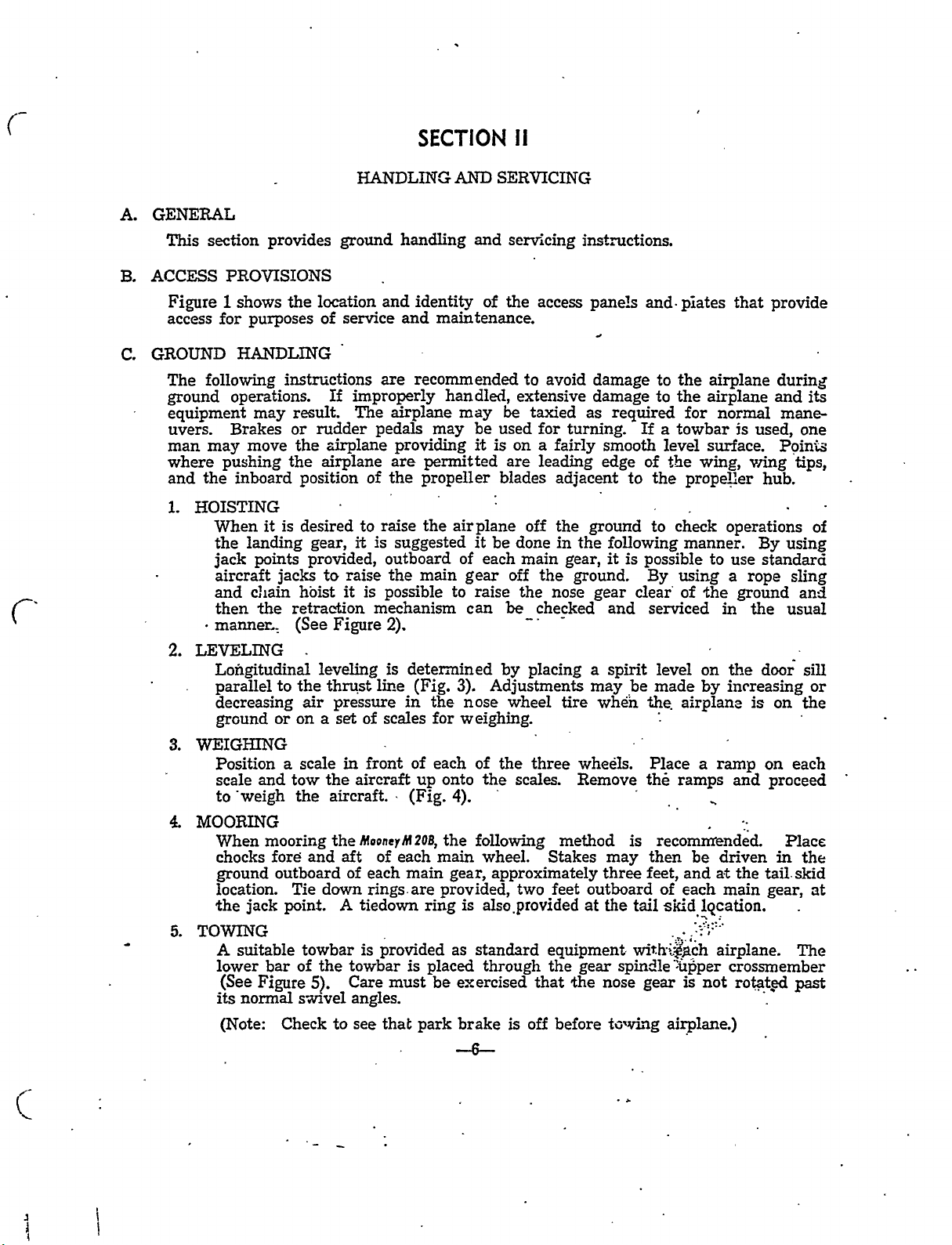
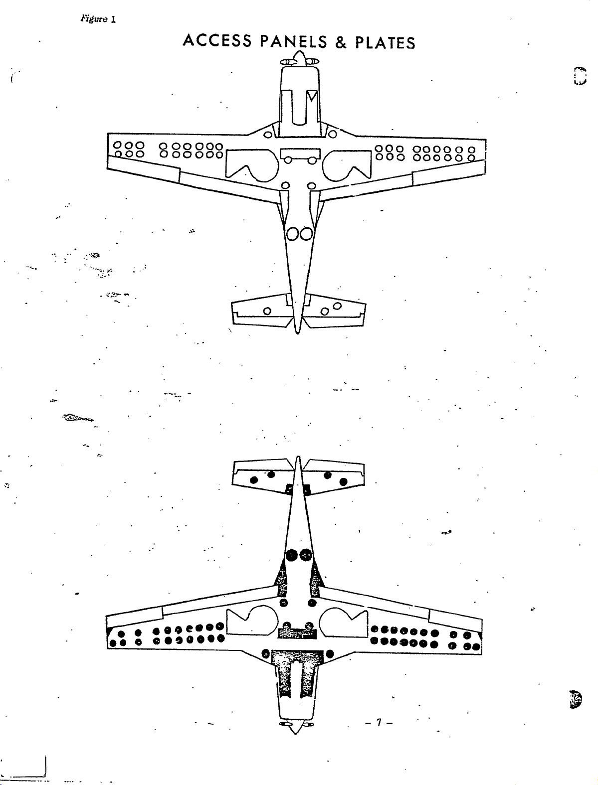
ACCESS
Figure
access
GROUND
The
ground
equipment
uvers.
man
where
and
HOISTING
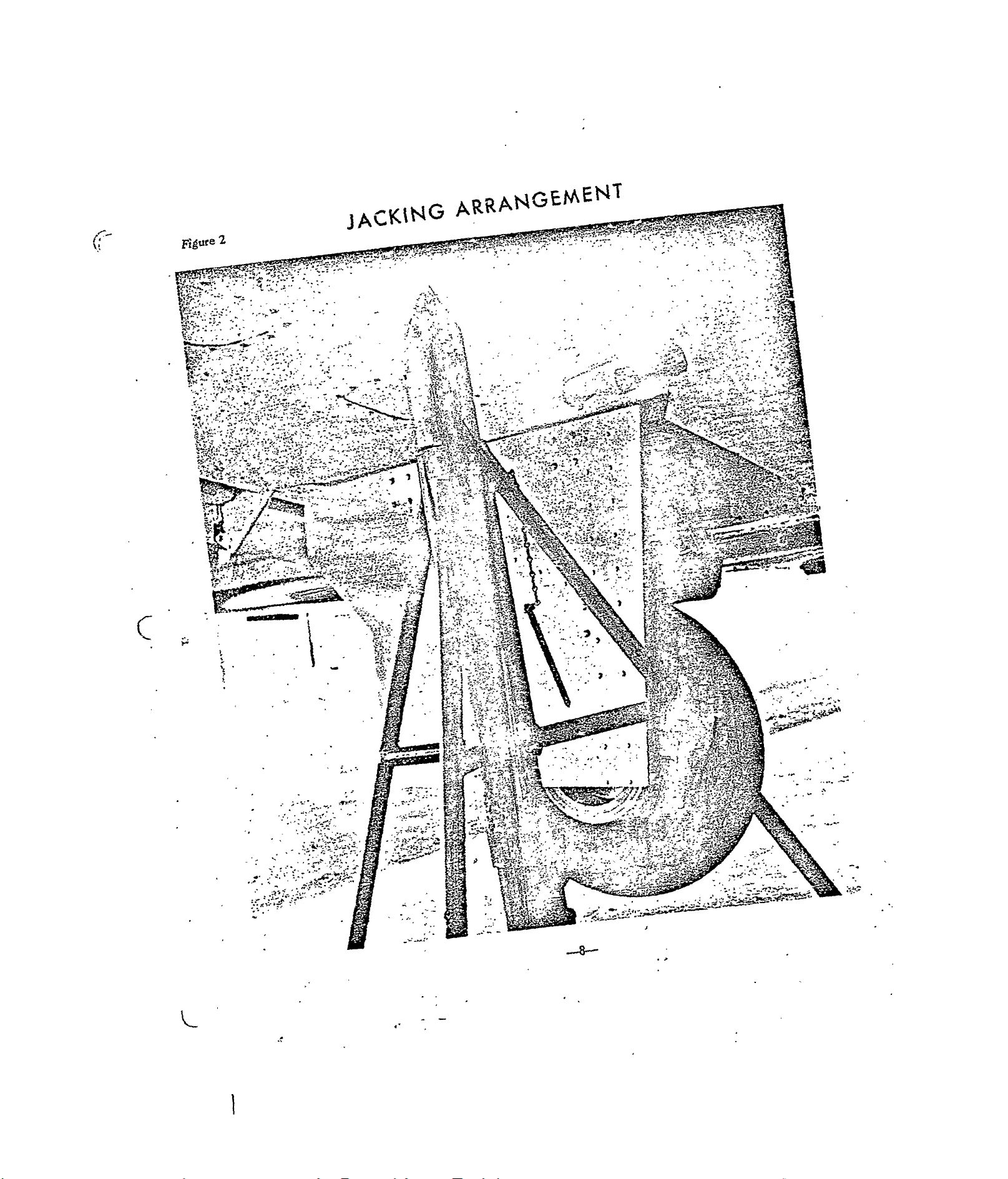
1.
2.
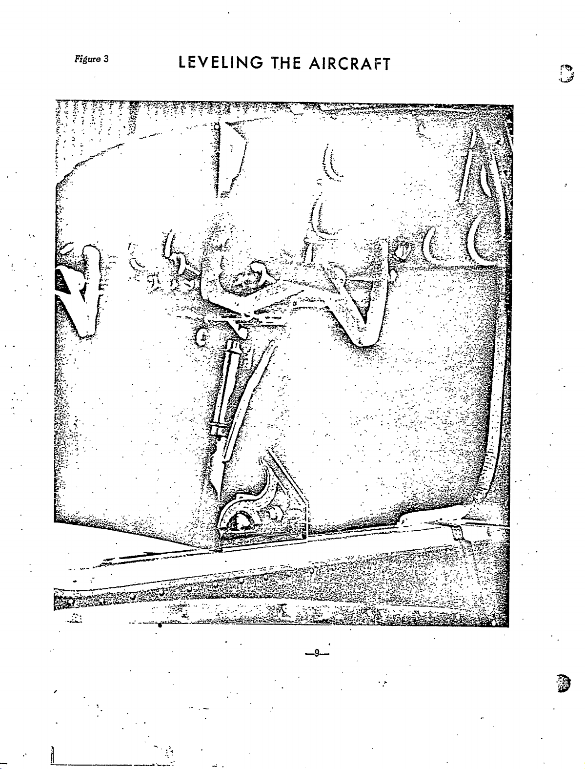
LEVELING
3.
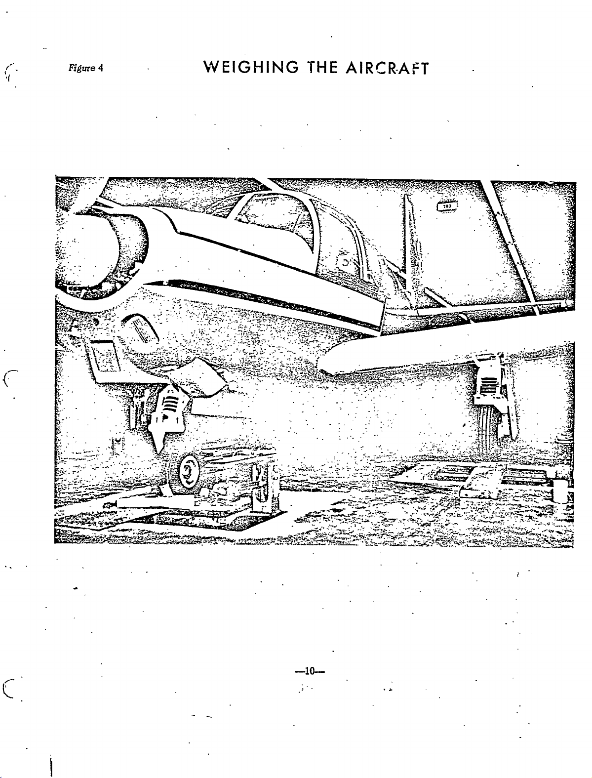
WEEGGHING
MOORING
4.
5.
section
PROVISIONS
1
shows
for
purposes
HANDLING
following
operations.
may
Brakes
move
may
pushing
the
inboard
When
the
landing
points
jack
aircraft
c!lain
and
the
then
manner,,
Lo~tigitudinal
parallel
decreasing
ground
Position
and
scale
to’weigh
When
chocks
ground
location.
´•the
jack
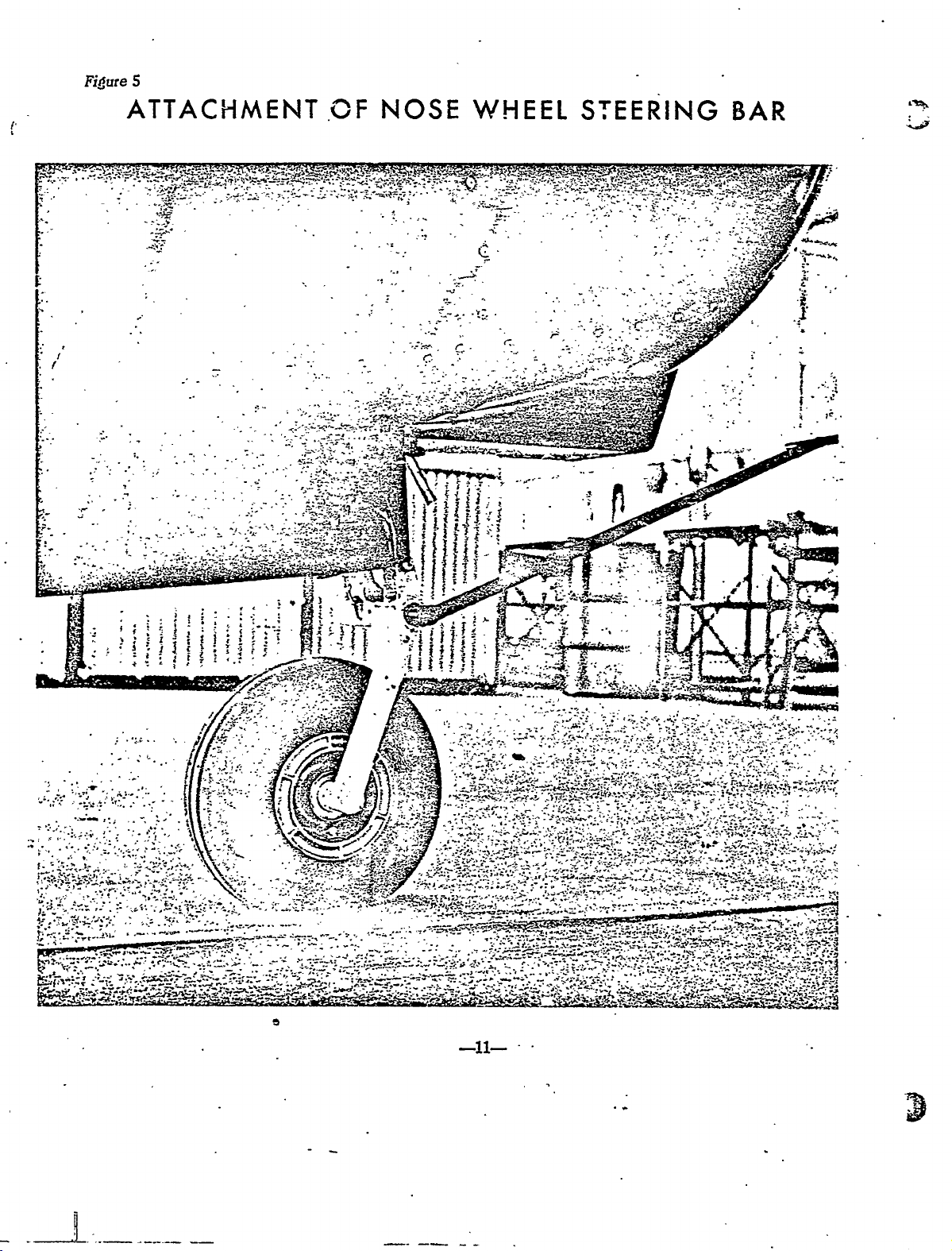
TOWING
A
suitable
lower
(See
Figure
normal
its
(Note:
provides
the
instructions
result.
or
the
the
position
desired
is
it
jacks
hbist
retraction
(See
the
to
air
or
on
scale
a
tow
the
mooring
fore:
outboard
Tie
point.
towbar
of
bar
s~vel
Check
HANDLING
ground
location
of
If
rudder
and
service
are
improperly
The
pedals
airplane
airplane
of
raise
to
is
it
gear,
provided,
raise
to
it
is
possible
mechanism
Figure
leveling
thrust
a
the
aircraft.´•
and
down
the
5).
line
pressure
set
in
of
front
aircraft
scales
theMooncyMZOB,
of
aft
of
each
rings.are
A
tiedown
is
provided
towbar
Care
angles.
see
that
to
handling
identity
and
recommended
airplane
may
providing
are
permitted
the
propeller
the
suggested
outboard
main
the
2).
determined
is
(Fig.
in
the
for
of
each
up
(Fig.4).
each
main
ring
is
placed
must
be
park
AND
and
of
maintenance.
handled,
may
be
is
it
airplane
it
be
of
each
gear
raise
to
can
3).
Adjustments
nose
weighing.
of
onto
the
the
following
wheel.
main
approximately
gear,
provided,
is
also~provided
standard
as
through
exercised
brake
--6
SERVICING
servicing
the
access
avoid
to
extensive
be
taxied
used
for
on
a
fairly
are
leading
blades
off
done
main
the
off
the
be
by
wheel
the
nose
checked
placing
three
scales.
Stakes
feet
two
equipment~
the
that
off
is
before
instructions.
pane~
damage
damage
as
turning.
adjacent
the
ground
the
in
gear,
ground.
gear
a
may
tire
wh~i´•1
whe~s.
Remove
method
outboard
at
gear
the
required
If
smooth
of
edge
to
following
it
is
possible
clear’
and
spirit
be
is
may
three
the
tail
nose
gear
and
plates
to
the
the
to
for
towbar
a
level
the
the
to
By
serviced
the
Place
the
then
feet,
wing,
propeller
check
manner.
using
of
the
level
on
made
by
airplane
a
ramps
recomnrended.
be
and
of
each
is
not
airplane.)
that
airplane
airplane
normal
is
surface.
vring
operations
to
use
a
rope
ground
the
in
the
increasing
is
ramp
and
driven
the
at
main
airplane.
crossmember
rotat_ed
provide
during
and
mane-
used,
Poin~
hub.
By
standard
door
on
on
proceed
in
tail´•skid
gear,
its
one
tips,
of
using
sling
and
usual
sill
or
the
each
Place
the
at
The
past
~dvre?
OLDWILLWAYNE
I.
.-´•~s
000
00
8
000
00000
ACCESS
PANELS
oU~I--YO
8,
PLATES
000
000000
00000
001_/3Lo--d000
00
r’~
o
oO
CD´•J90~9
8888888
-7-
8
Figure
OLDWILLWAYNE
KING
p~lRANGEMENT
L
3A~1
Z
::i
-´•I´•~:
..I
\‘:2.´•
i,-
´•´•.r
t~
.t~´•:
´•r’:´•-.
.~´•z
I.’
--r
?~t
:r~-;c´•
:j:
-i´•.-
5*
Ing
f
r
t
:~4
~zt
~T
~C
´•,s
~´•le
i-
´•ij´•
’’I
~s
B:
´•I
~ic;.;
5
3;
1
ii;r-
´•_
ir--
´•-´•r´•
’5´•
6i3
~p
~$s1.:
c
?:ic
~Z
´•’~1
t~
.~5
’c’~--
~d
´•-L‘~
C~
5--
f
-J
I
.I’´•r
r:i
-i
j.~
:i´•´•
t~
)5
!~L
--~i´•x
~.-.i
.k
j3
’r
C
’~fr.b
:,j
*~r´•-:
´•´•.t
-,ri~i´•´•´•
ljSP’9
C;
´•r
‘I:
.:6´•
e.r.´•
:-e
´•´•r:
:i
’i
’I
c::
::C;.L
’i~
;I
^-.V
i
:r
p
*j
i
i
,c,
r-
9i’7~-g
r~
:il´•
E
;z-
i
;2;
.´•Y~
pr
r,:s
.i
j~
,Tr;
r’
~iur
-´•.4(..’.´•
,s*
irC
ii´•.
i‘´•~
u´•
~n
::nS+i-~
I
t´•
r
’r
I"’
I
Figute
OLDWILLWAYNE
I
5
3
~1:
LEVELING
;i
s
THE
f
AIRCRAFT
~P
´•1~
:1’
L1;´•t
r
4~
_r
Y
4i~
ic~
BTr
r
a
J
c
~j´•-
Li´•il.
Y~:
a
Ld~s´•
f~ri
5´•~1
E~ij
I
i
r
,~s
ri
~1
i
CIIC
7..
41
´•-~´•t-..2
b,c~
t
´•-~s,
4
i:
i´•
J
;,´•v
~r´•
I
r
´•i:
-.-´•´•;-:1
s´•
.1.I.
C
i
I’
L;-:´•
r
C
i
t~i
".Zp
,.I-.
7.
A
e´•~
´•C&i’~
~r:,
´•r´•~.
M
I--
L1
-´•C~
´•:´•I
L’:
~iS:
-i~-
3
El-
r~
res
´•r
r~´•´•L:
Mr
v´•,
r´•´•r
-:T~Z
’~Mz:
´•r~.
re
-~r
i;
.7’
T~
c;fi:
1´•´•
L-´•-
,a
Figure
OLDWILLWAYNE
4
L~EIGHING
IHE
AIRCRAFT
´•ii
:Jr-~
ir..
,t
-.e
1:
c
´•´•I
.f
-I
il´•.´•
´•F:´•
ra
ii.-
B´•-
´•~N
I--
-J~’´•.
-i´•-
:´•r´•
~sl
i.
p~a
Y
s´•i~
-‘---n
g
i
’i’i
21~
-dv
L´•
--L-
E~
;~f-
~L´•
i~i-.
a
.I
it
s~
-~--.´•--I
-~P-
ti
7~-
´•;--´•~s.W
´•---~Y
;.1
iR3
f4
d
3
I.:-
.I
f?_~
-ii´•..l´•
i--
TI
~t
’t’
´•i-´•.Y
c~
d
.:;iiii
i
´•-L´•i
L’´•.i
2~
-2
-i~1´•
r
t
--1"
5
OLDWILLWAYNE
Fi~ure
ATTACHMEr\aT
NOSE
i
MII1EEL
4.
SIEERING
~t´•r’E
r
BAR
~h
ii_
E
I
,k´•-‘-
´•-I
I
~-i-
:1-
.C
z
.’r;C
-ca--´•
-rF;7
i:
51
’r
i
ft5i
I.t~
I
c
4j
r
f
C1..
-t
s
r
3
Xe’
C-
!3~1r
i
If~
f
tiI
t1
~t
7
I
i
´•ii
i
i~
i
i-ri
t’t´•
’i;
i
f
Ij
i-~
c
r"-
~a
I
I
r
f’
:--1
ii
i´•
~6,,´•;i
1"
i
´•´•p:
.r:
B
a
f
t
,z
f
i
.I
t´•-~;
.L:;´•’
~r
i-;
’I
2.;,?´•
7-´•’
-1
i
~7
i
i.:
-ii.
Tf
t
_´•.-
::I:.~
;´•’.’r´•~´•´•
Z;
´•´•´•´•~C;i’
Z~a
i
Z"
´•´•’1.
i~-4‘t-.
.-´•.´•---I~
C
J~z
?i:
’.´•i´•
r
C-
´•´•´•Elh
´•-J
´•´•~.r
15
.I:
.n.
´•r´•
li´•
sc
-s";
,,,r
L~
f
i
´•z
r:’
;1
Z-
-----1~--
D.
OLDWILLWAYNE
SERVICMG
1.
FUEL
f~.
I~UBE
a.
b.
c.´•
a.
SYSTEM
Filling
Each
sible
pansion
gasoline
located
each
of
Fuel
The
equipped
dirt
Draining
Drain
bottom
turned
OIL
Filling’
Fill
The
Fuel
wing
for
filling
type
spilled
on
fuel
Strainer.
fuelstrainer
rrith
accumulations
Fuel
the
of
on
SYSTEM
Engine
’the
engine
intragal
gas
the
cell.
System.
fuel
the
the
Sump.
Cells.
by
cap.
outside
intoard
(r’igure6)
an
from
fuel
tank
sump
fuel
lifting
easy
and
the
selector
being
with
cell
A
scupper
the
corner
drain
drained
system
has
a
dzus
a
filler
under
is
located
regularly,
by
valve.
drained).
the
lubricating
capacity
fastened
box
neck
each
and
removing
(Note:
of
drain
opening.
wing.
in
should
the
oil
24
Il.
door
is
provided
The
This
the
nosewheel
be
the
fuel
spectfied.in
S.
gallons
and
checked
flush
selector
removmg
to
fuel
is
the
drain
valve
Table
and
drain
cell
lowest
well.
for
is
drain
water
from
must
i.
the
off
acces-
point
It
ex-
any
is
is
or
the
be
b.
r
3.
BI~AKE
b.
E.
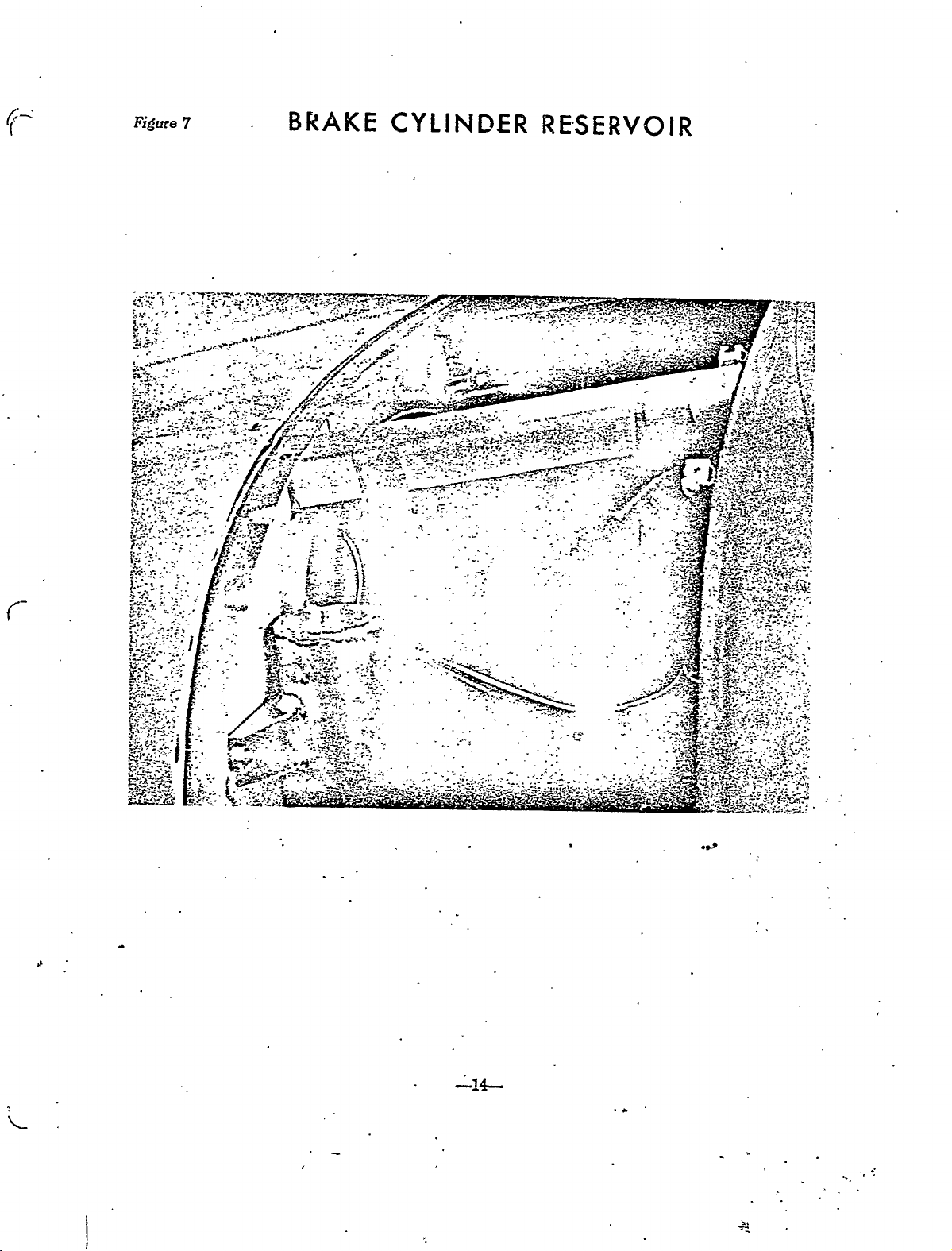
LUBRICA’I~ION
Refer
time
intervals,
and
gear
of
the
lubricants.
_.of
and
grit,
Where
a.
sealed
The
SYSTEM
Filling
The
fluid
tion
land
of
is
Draining
Tb
discs
system
to
the
type
and
a
Draining
engine
is
brake
and
Disc
the
set.)
drain
the
and
main
Excess
may
reservoir
Engine
installed
Brake
cylinder
specified
replenished
Brakes
brake
the
the
and
slowly
can
Lubrication
Srpe~
gear.
and
do
lubricant
lead
is
Sump.
sump
Cylinder
in
lining.
Brake
brake
be
cleaned.
of
Bearings
not
to
malfunction
not
can
each
in
reservoir
Table
when
require
System.
system,
pump
Chart
lubricants
require
on
provided
easily
be
MooneyMiO~i
Rsservoir.
iFigure
It
1.
necessary.
no
~pen
the
brakes
by
flushing
(Figure
used.
used
per’iodic
of
around
adjustment
in
(Caution:
exterior
-drained
should
Do
´•t~4e’brake
8)
Grease
´•bell
lubrication.
surfaces
the
unit.
a
airplane
7)
be
After
not
until
out
with
instructions
for
cranks,
bearing,
means
by
as
must
checked
initial
whatever,
fill
reservoir
bleeder
all
the
denatured
fittings
hinge
Avoid
of
bearings
apply
of
standard
be
filled
at
every
installation,
during
fluid
regarding
are
points,
the
the
equipment.
while
va13e
runs
alcohol.
provided
and
excessive
tends
lubricant
oil
with
100
the
parking
on
out.
to
quick
the
hour
inspec-
the
Cleve-
service
the
The
the
location,
the
on
rod-ends
application
attract
sparingly
drain
brake
life
brake
brake
brake
nose
are
dirt
-12-
FigureB
OLDWILLWAYNE
FUCL
L
STRAINER
DRAI~I
~s
´•Lia~
-´•i´•’
r´•.
P
I
3jC
r-
t~L.
S
Y´•
-´•r
~C’
~L1?I1-C
).f
"I~S
’i´•
u.
B;i
c,i
1~
5~
,Ir.13;p~´•
1
..,2´•
s
r
´•C
’CQ
-13-
-e
Figme
OLDWILLWAYNE
7
BKAKE
CYLINDER
RE´•SERVOIR
::?’´•~t
k
t´•,´•´•.l´•
ii
;’r
1
c
r
I"
´•I_
~T’
:~L_.
z
~LTI2´•1
d
T´•1´•
~s´•
~J
ib
i,
I
s
-\j´•~
:sl::
f
P:.
cI-;´•
i-.
":i
u
t
f~
"~’.QF
-i-
)i;
r´•F.i;
8~
L
i-.
.~i
:3:
.-´•a:2;.
r;
-;s~
.j.
"35.1~
.5
..,i
.~m;´•r´•
´•c~:
:n
i~72;r
1
T
i5~7;
--r-1
i~
L´•.~x.,r
´•c~a
2~;
;´•S
?1
~1
--I
Figure
OLDWILLWAYNE
8
LUBRICATION
CHART
FOR
MOONEY
20B
M
Trim
system
Control
Brake
fluid
side
Rudder
Frontseat
Nose
Starter
Carburetor
SAE80
Propeller--See
McCauley
NoseSear
tot31...11´•L.
4
Column
reservoir,
level
indicated
maintain
oireservoir..´•--´•´•´•.´•´•´•´•´•´•---´•´•´•
control
system.,.c.,.,100
adjustment...l.--10D
wheel
bendfx
air
to
oil,
propeller.
grease
steering
iilter,
reoil,.,...~.
note
fittinbs,
I-´•´•-´•´•´•-´•-´•´•CI1´•´•-´•--100
HOURS
the
on
....~.--.100
use
6
Tot
V’,
50
~c\‘
25.´•´•
25
//’e
KOURS
Rudder
100
e-
I
1/
100
Stabiiizer~inges
100
Adjustment
:00
Baggage
door
!30
Aileron
bei!crar?k
100
Hinges-Main
2
100
Main
fittings
5
~I
100
Main
right
100
Landing
hinges
and
and
each
landing
right
each
wheel
and
mechlnism
door
latches
right
left.
gear
and
and
hinges,
fla?
and
gear
gear
and
bearings
horn
main
left
doors.
grease
left
retractionsystem
50
Engine
refill.
8
qt.
oil
tank,
(n’on-detergcn~)
drain
and
wheel
Nose
Hinges--Nose
total.
2
i.
Fuel
,yslcm
Fuel
A.
B.
Carburetor
Filterbowl--
C.
D.
Buick´•drain
Miscellaneous
2.
cation
not
Do
3.
Do
4.
not
~fg
bcaring..................100
wheel
pump
Door,
The
strainer--
screen--
u;dt.
following
During
misccllan~=us
to
a
use
hydraulic
over-lubricate
Check
t~ltery
routine
linkages.
nuid
pedestal
T,uid
points
with
cbnCtala
level,
require
maintenance
a
casbt
an~
Ewlr
OL
regular
oil
or
battery
serviciag.
checks,
ester
condition
apply
base,
lubrica-
every
NOTES
29
6.
McCauley
disassernbled.
Do
7.
8.
Remove
not
100
apply
all
propelle,p
lubricant
excess
are
grease
100
prelubriealed
to
rubber
from
SeE
SAB
SAE
parts.
grease
OlGNON-DETERCENT
50
above
3(1
above
20
below
end
need
fi~ttings.
LEGEND
40’
air
10.
and
air
10’
temp
below
temp.
no
100
lubrication
40.
temp.
until
LEGEND
MILL-7870
a
MILL-7711
MIL-LS545
O
M1L-G-3´•278
I/
-C,
MIL-O-5666
i
Graphite
Graphite
Powdered
X~
I
__
I
Oil--GeneralPurpose
low
temp.
Grease--lubrication--
general
Grease--lubrication
hign
Grease--aircraft
instruments
purpose
temperature
HydraulicRuid(Ked)
kel~sene
and
MlL-G-S278
ana
g~aphite
lubrication
aircraft
and
grease
DoorE.seorequiv.
-13-
rollers
OLDWILLWAYNE
for
following
wheel
When
and
lubrication
bearings
repacking
the
retainer
precautions:
from
with
of
mechanisms
ring.
the
grease,
wheel
Do
hub
be
sure
not
pack
requiring
and
the
lubricant
the
lubrication
clean
grease
wine
the
the
off
any
wti~
space
wheel
available,
c~cgss.
suitable
a
bet~een
hub.
specific
observe
r
and
thorou~ly
enters
into
Whenever
not
are
Remove
solvent.
the
instructions
the
C
it
oils.
has
The
i.
2.
been
The
Apply
Squeeze
appears
oil.
during
engine
quality
ubserved
proper
ail
the
on
Be
careful
operation
manufacturer
brand
grades
sparingly,
ma,aneto
the
fingers,
not
Aviation
the
that
of
and
oil
to
never
add
will
does
best
are
cam
do
Grade
morc
foiler
not
too
cause
not
overall
listed
than
felts
add
oil.
much
oil,
pitting
recommend
of
results
below.
the
Oil
enough
at
regular
If
the
because
and
proper
are
to
-felt
burning
oils
obtained
the
coat
~inspection
is
dry,
the
excess
of
brand
by
seasonal
bearing
periods.
moisten
will
the
magneto
names.
viscosity!
from
surfaces.
If
with
be
light
thrown
points.
Use
However,
non-detergent
oil
off
a
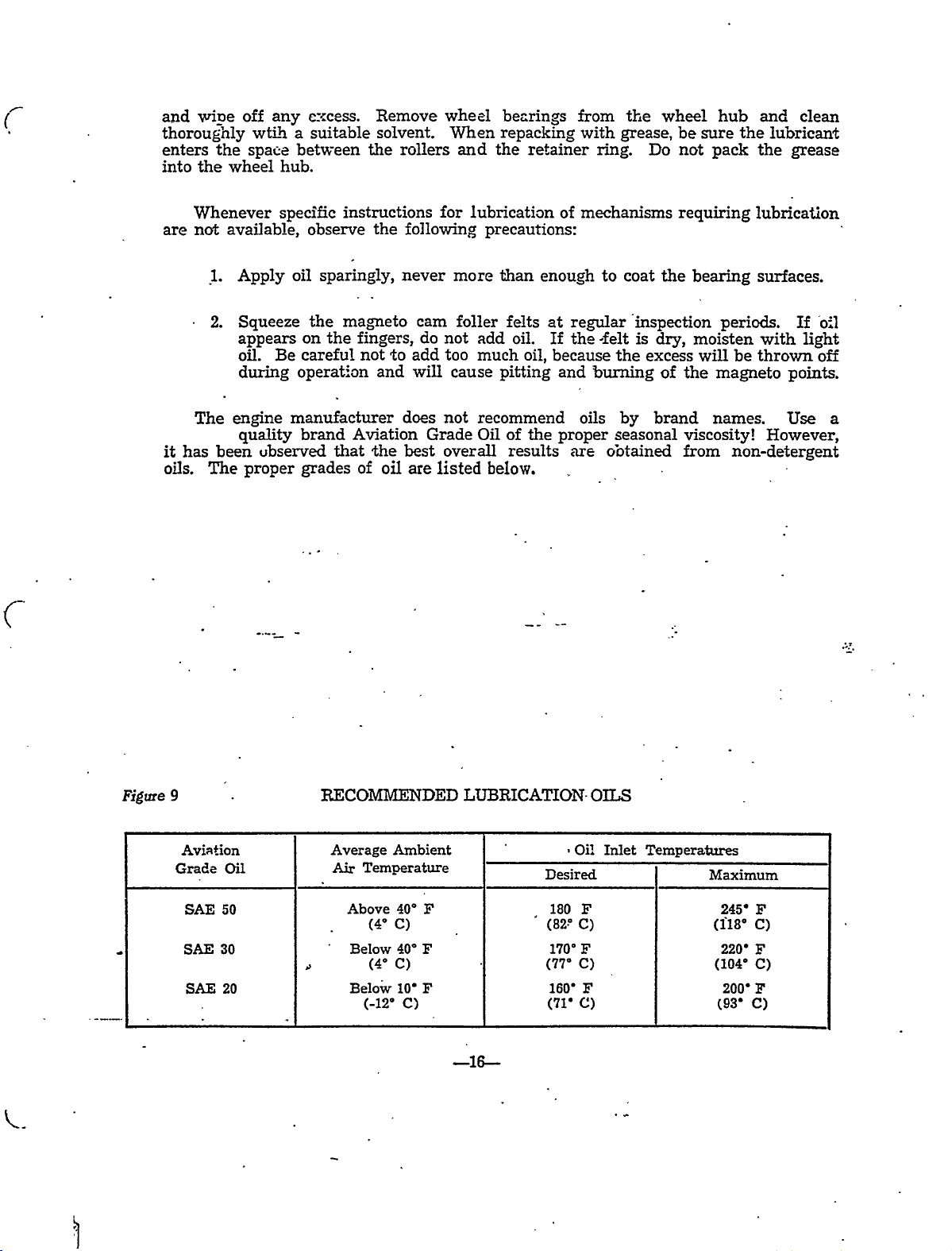
Figure
9
Aviation
Grade
SAE
SAE
SAE
F
F
F
LUBRICATION
--ZC
Desired
180
(82’
170"
(17"
160’
(71’
Oil
F
C)
F
C)
c,
F
OILS
Inlet
Temperatures
Maximum
245’
(i18’
220’
(104"
200’
(93’
F
C)
F
C)
F
C)
RECOMMENDED
Temperature
Above
(4"
Below
(4"
Below
(-12’
Ambient
40"
C)
40"
C)
10’
C)
Average
Oil
50
30
20
Air

SECTION
OLDWILLWAYNE
POVVER
PLANT
r:
OLDWILLWAYNE
SECTICN
)II
C
A.
GENERAL
Thel#00NEr
pression
engine
vibration
of
porates
This
and
mounts
the
1.
2.
3.
longer
1.
engine.
to
the
to
following
New-type
hardness.
New
pistons,
180
degree
all
in
mixture
engine
ignition
bendix
Two
breaker
M
203ispoweredby
rated
It
is
dynamically
cabin.
improvements:
cylinders
compression
oil
conditions
the
in
utilizes
life.
magnetos,
points.
at
balance
It
is
which
temperature
of
flight
intake
the
It
manifold
latest
consists
POWER
180
the
and
and
ignition
theleft
newest
PLANT
the
famous
horsepower
the
engine
version
have
tapered
oil-scraper
thermostat
to
give
system
of
the
following:
magn’eto-being
at
in
bores
rings
to
better
which
Lycomiug
2’i00
Zigh´•t
of
this
and
for
provide
vaporization
equipped
0-360-AID,
RPM
and
to
type
are
longer
optimum
a?d
reduce
engine
nitrided
engine
uses
oil
of
gi\res.quicker,
with
a
high
dynafocal
tr3nsmission
c~ind
incor-
for
extra
life.
temperature
the
fuel-air
easier
set
starts
retard
of
com-
The
91/96
further
turer’s
TROUBLESHOOTING
B.
Troubles
their
´•’t--rktommend
the
on
A
2.
3.
starting
shower
switchwhich
A
4
Shieided.spark
of
Lycoming
octane
fuel.
detailed~information
applica~ble
~publications.
peculiar
that
causes
the
system.
probable
ignition
vibrator,
sparks
0-360-AID
It
also
to
and
magneto
located
for
combines
and
plugs
engine
uses
a
on
the
Mooney
suggested
primary
starting.
both
ignition
has
McCauley
the
engine.
Power
remedies.
-17-.
on
ignition
circuit
the
harnesses
8.5
an
2D36C14
or
Plant
uplier
and
to
the_
When
be
fire
wall,
starting
to
suppress
1
compression
Constant
propeller
listed
are
troubleshooting
grounded
and
functions.
Speed
refer’fo.the
in
before
which
radio
ratio
Propeller.
Table
this
performing
and
2
furnishes
noises.
engine,
a
requires
B’or
witli
we
checks
Table
OLDWILLWAYNE
r~zh
2
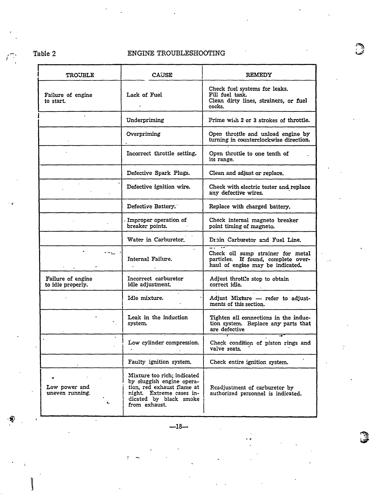
ENGINE
TROUBLESHO~TING
Failure
to
start.
TRO’JBLE
of
engine
Lack
Underpriming
Overpriming
Incorrect
Defective
Defective
Defective
.~proper
breaker
Water
~I
InternalFailure.
of
in
CA’JSE
Fuel
throttle
Spark
ignition
Battery.’
operation
points.
Carburetor.
setting.
Plugs.
wire.
of
Check
Fill
Clean
cocks.
Prime
Open
turning
Open
its
Clean
Check
any
Replace
Check
point
I
DIlin
Check
particles.
haul
fuel
range.
defective
timingof
of
fuel
systems
tank.
dirty
wi;n
throttle
in
counterclockwise
throttle
and
adjust
with
with
internal
Carburetor
oil
sump
If
engine
REMEDY
lines,
2
or
and
to
electric
wires.
charged
found,
for
strainers,
3
strokes
unload
one
or
replace.
tester
magneto
magneto.
a?d
strainer
may
leaks,
tenth
and.~eplace
battery.
breaker
Fuel
complete
indicated
be
or
throttle.
of
engine
directioa
of
Line.
for
fuel
by
metal
over-
Failure
idle
to
Low
uneven
of
properly.
power
running.
engine
and
Incorrect
idle
Idle
Leak
system
Low
Fault~
Mixture
by
i
night.
I
i
1
from
sluggish
tion,
dicated
carburetor
adjustment.
mixture.
the
in
cylinder
ignition
too
red
exhaust
Extreme
by
exhaust.
induction
compression
system.
indicated
rich;
engine
flame
cases
black
opera-
smoke
Adjust
correct
Adjust
ments
Tighten
tion
are
Check
I
valve
Check
at
in-
Rfadjustment
authorized
i
thrott’e
idle.
Mixture
of
all
system
defective
condition
seats.
entire
this
connections
personnel
section.
ignition
stop
Replace
of
of
carburetor
to
obtain
refer
any
piston
system.
is
to
in
the
parts
rings
indicated.
adjust-
induc-
that
and
by
~e
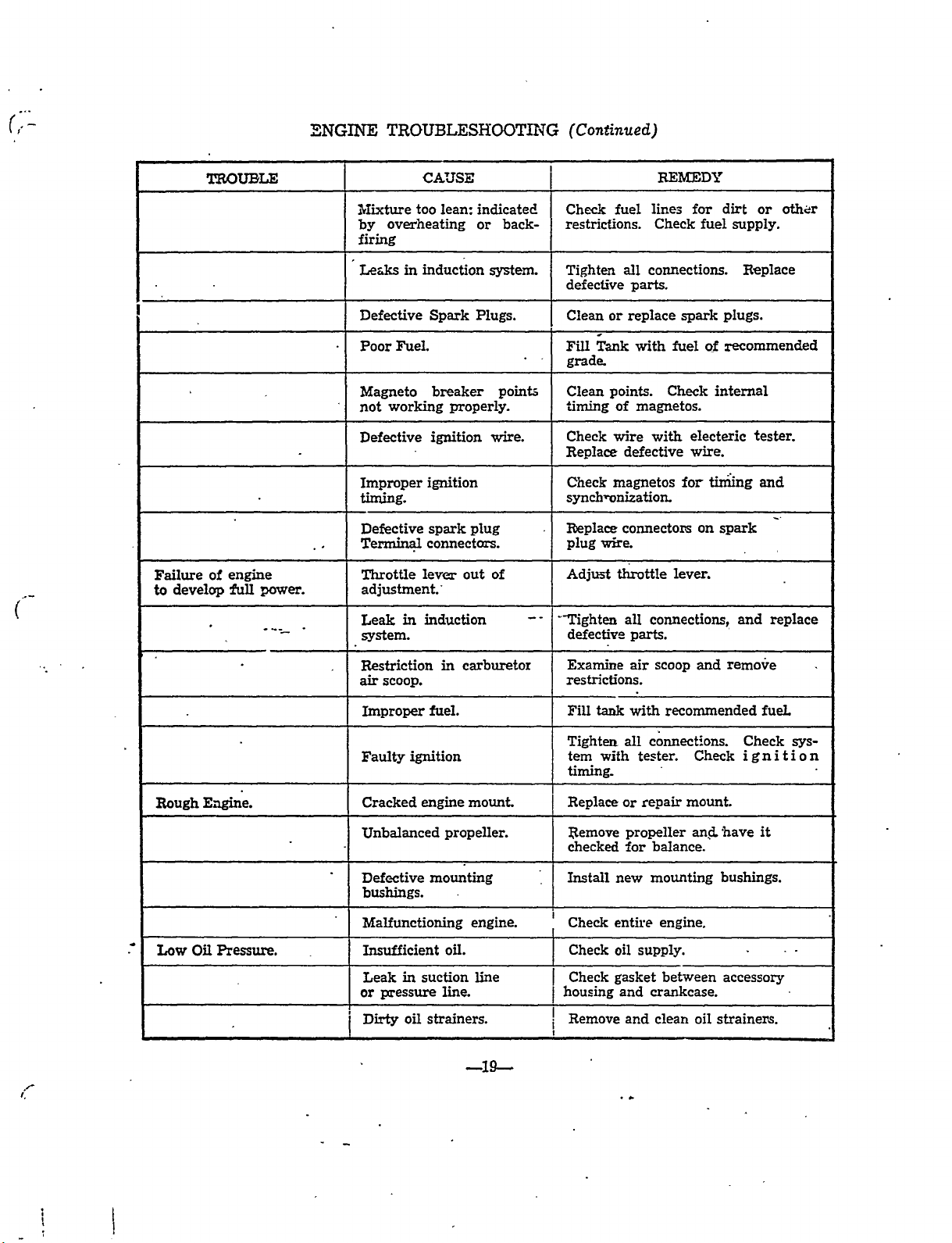
~NGINE
OLDWILLWAYNE
(Con~inued)
I
Failure
to
develop
of
engine
~Pull
power.
Mixture
ove~heating
by
firing
Leaks
Defective
Poor
Magneto
not
working
Defective
Improper
timing.
Defective
Terminal
Throttle
adjustment.~
Leak
I
system.
Fuel
in
too
in
C~JSE
lean:
induction
Spark
breaker
properly.
ignition
ignition
spark
connectors.
lever
induction
indicated
or
Plugs.
plug
out
back-
system.
point;
wire.
of
Check
restrictions.
Tighten
defective
Clean
or
ihnk
Fill
grade
Cleanpoints.
’riming
Check
Replace
Check
synch~onization
Replace
I
plug
wire.
Adjust
I~"righten
defective
lines
fuel
Check
connections.
all
parts.
replace
with
of
magnetos.
with
wire
defective
magnetos
connectors
tI;rottle
all
connections,
parts.
REMEDT
far
fuel
spark
fuel
Checkinternal
electeric
wire.
for
on
lever.
dirt
supply.
Replace
plugs.
of
recommended
tiniing
spark
and
or
tester.
and
replace
oth~
Rough
Low
E;lgine.
Oil
Pressure.
Restriction
air
scoop.
Improper
Faulty
Cracked
Unbalanced
Defective
bushings.
Malfunctioning
Insufficient
I
in
Leak
or
pressure
Dirty
ignition
engine
suction
oil
strainers.
carburetor
in
fuel.
propeller.
mounting
oil.
line.
-19-
mount.
engine.
line
Examine
restrictions.
Fill
Tighten
tem
timing.
Replace
Remove
checked
Install
Check
Check
Check
hou´•ing
I
Remove
j
tank
with
air
with
connections.
all
tester
or
repair
propeller
balance.
for
new
mounting
entire
oil
supply.
gasket
crankcase.
and
and
and
scoop
recommended
Check
mount.
and
engine.
between
oil
clean
remove
Check
ignition
have
bushings.
accessory
strainers.
fuel
sys-
it
TROUBLESHOO’TI~U’G
OLDWILLWAYNE
(Continued)
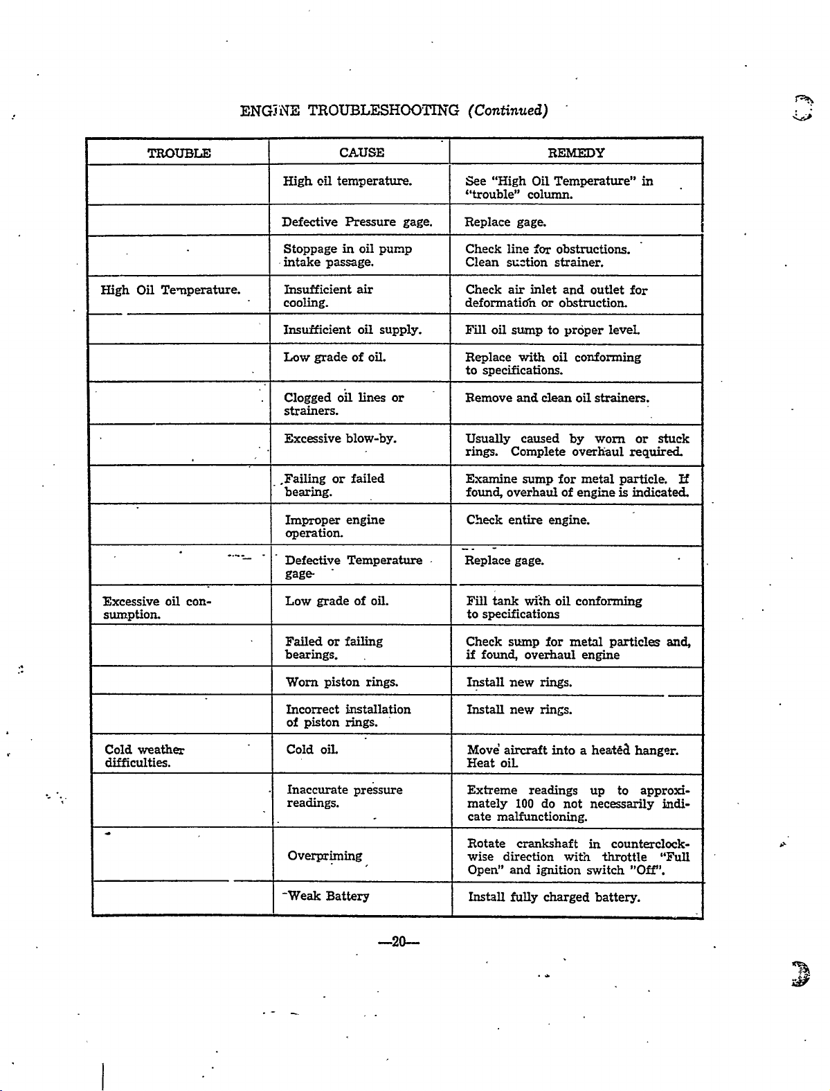
High
TROU&I;E
Oil
Temperature.
oil
High
I)efective
Stoppage
intake
Insufficient
cooling.
Insufficient
Low
grade
Clogged
strainers.
Excessive
.Failing
bearing.
Improper
operation.
CAUSE
temperature.
Pressure
in
oil
passage.
air
oil
of
oil
Lines
blow-by.
failed
or
engine
pump
supply.
oil.
or
gage.
See
’’trouble"
Replace
Check
Clean
Check
deformatidn
Fill
Replace
to
Remove
I
Usually
rings.
Examine
found,
Check
On
"High
column.
gage.
lir?e;cor
s~r=tion
inlet
air
or
oil
sump
with
specifications.
andcleanoilstrainers.
caused
Complete
sump
overhaul
entire
REMEDY
Temperature"
obstructions.
strainer.
and
outlet
obstruction
to
prdper
oil
conforming
worn
by
overhaul
for
metal
of
engi?e
engine.
level
particle
is
in
for
stuck
or
required.
indicated.
Ef
Excessive
sumption.
Cold
difficulties.
weather
Defective
gage
oil
con-
Low
Failed
bearings.
Worn
Incorrect
of
piston
Cold
I
I
Inaccurate
readings.
Overpriming
-Weak
grade
or
piston
oil
Batterg
Temperature
of
oil.
failing
rings.
instailation
rings.
pressure
Replace
I
I
Fill
to
Check
if
Install
Install
Move’
Heat
Extreme
mately
cate
Rotate
wise
Open"
install
gage.
tank
wi~h
specifications
sump
found,
overhaul
new
new
aircraft
oil
readings
100
malfunctioning.
crankshaft
direction
and
fully
oil
for
rings.
rings.
into
do
ignition
charged
conforming
metal
engine
a
up
not
necessarily
in
with
switch
particles
to
counterclock-
throttle
battery.
and,
hanger
approxi-
indi-
"Full
"Ofir’.
-2e
C
OLDWILLWAYNE
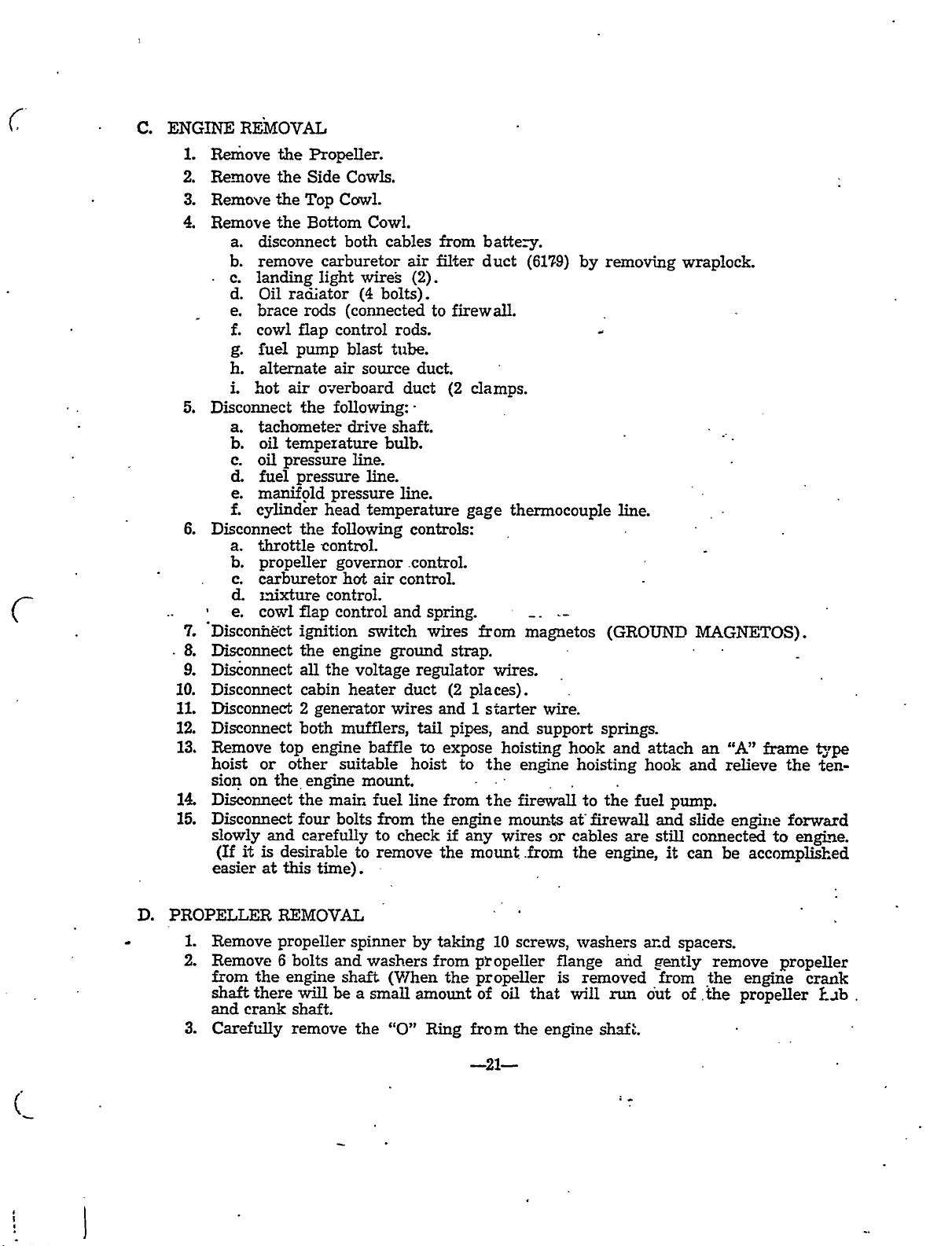
ENGINE
c.
1.
2.
3.
4.
5.
6.
7.
8.
9.
10.
11.
12.
13.
14;
15.
REMOVAL
RemovethePropeller.
the
the
radiator
flap
pump
air
the
temperature
pressure
pressure
the
tnixture
flap
ignition
the
all
cabin
2
both
top
other
or
the~
the
four
and
carefllUv
is
desirable
this
at
Side
Cowl.
Bottom
carburetor
rods
control
air
overboard
following:´•
pressure
head
following
rontrol.
governor.control.
control.
control
engine
the
generator
engine
suitable
engine
main
bolts
time).
Remove
RemovetheTop
Remove
disconnect
a.
b.
remove
c.
landinglight
d.
Oil
brace
e.
cowl
f.
fuel
g.
h.
alternate
hot
i.
Disconnect
tachometer
a.
b.
oil
oil
c.
d.
fuel
manifold
e.
f.
cylind~
Disconnect
throttle
a.
b.
propeller
carburetor
c.
d.
co~l
e.
Disconi~ct
Disconnect
Dis~onnect
Disconnect
Disconnect
Disconnect
Remove
hoist
sion
on
Disconnect
Disconnect
slowly
it
(If
easier
Cowls.
Cowi.
both
cables
wireg
bolts).
(4
(connected
rods.
blast
source
drive
shaft.
bulb.
line.
line.
temperature
hot
air
and
switch
ground
voltage
heater
wires
mufflers,
baffle
mount.
fuel
from
to
check
to
remove
air
(2).
to
duct.
duct
line.
controls:
control.
sprin~
wires
regulator
duct
tail
to
hoist
line
the
from
filter
firewall.
(2
strap.
(2
and
pipes,
expose
from
engine
if
the
battery.
duct
clamps.
gage
~from
wires.
places).
1
starter
and
hoisting
the
to
the
wires
any
mount.from
(61~9)
by
thermocouple
magnetos
wire.
support
hook
engine
firewall
mounts
or
hoisting
to
at’firewall
cables
the
removing
line.
(GROUND
springs.
and
attach
hook
fuel
the
are
engine,
wraplock.
MAGNETOS).
and
pump.
slide
and
still
connected
it
can
an
"A"
frame
relieve
engine
to
be
accomplished
the
forward
engi~e.
t~pe
´•ten-
D.
PROPELLER
I.
Remove
2.
Remove
from
shaft
and
3.
Carefully
the
there
crank
RF~MOVAL
propeller
6
bolts
andwashers
engine
be
will
shaft.
remove
spinner
shaft
a
the
small
"0"
by
from
amount
Ring
taking
the
10
p~opeller
propeller
of
oil
from
the
screws,
that
washers
flange
is
will
engine
removed
run
shaft.
and
and
dut
from
spacers.
the
of.’the
remove
propeller
engine
propeller
crank
Elb.
 Loading...