

Mooney Executiv 21, M20F Owner's Manual
MODEL
M20F
OWNERS
MANUAL
OPERATE THIS AIRCRAFT
ONLY-
@after reading
owners manual @with owners manual on board
@
after you are fully qualified & understand all of
the aircraft operating characteristics& limitations
MOONEY
AlRCRAF7:
lNC.

YEAR
P
1967
OWNERS
MANUAL
MODEL
SERIAL
NUMBERS
M20F 660003 & 660004
670001
TWRU
670539
Issued
September
1966
Revised
March
1967
aboard your new Executive
21.
Enjoy the greater utility
of the long,
rooiny cabin. The far-ranging fuel capacity
of the Executive
21
now makes possible one-stop trans-
continental flights.
The same high
perforinance and low operating cost which
make its sister ships, the Mark
21
and Super
21,
the
world's leading sellers
in
the retractable-geared class,
are bred into the Executive
21.
Read this manual carefully, it is prepared to help you en-
joy fully the remarkable
perfor~nance and econorn)r charac-
teristics the Executive
2
1
is prepared to deliver.
MBONEY
AIRCRAFT,
INC.
XERRVIL 1 E TEXAS
This manual contains Federal AviationAgency- DelegarionOption
Authority approved li~nitarions and
nus st
be carried in the
Execu-
tive
21
at all times.
EXECUTIVE
21
OWNER'S
MANUAL
TABLEOFCONTENTS
PART
I
DESCRIPTION AND OPERATION
OF
COMPONENTS
Page
General
Propeller
Engine
Power Boost
Engine Ignition
Fuel System
Electrical System
Airframe
Landing
Gear
Flight Controls
Moaney Positive Control Systen.
Trim System
Flaps
Vacuum System
Brakes
Heating and Ventilation Systems
PART
II
FLIGHT
PROCEDURES
General
Weight and Balance
Pre-Flight
Inspection
Entering the Airplane
Starting the Engine
Cold Weather ond Manual Starting
Taxiing and Ground Operation
Pre Take-Off Check
Take-Off and Climb
Power Changes
Cruise Procedures
Indicated Airspeed
Fuel Management
Let-Down Procedures
Land
ing Procedures
Normal Landing
Stopping the Engine
PART I!! SERVICE AND MAINTENANCE
Page
General
Ground Handling
Propeller
Engine
Battery
Care
of
Interior
Care of Exterior
Windows
Landing Gear
Vacuum Operated Step
Required Data
Service Bulletins and Instructions
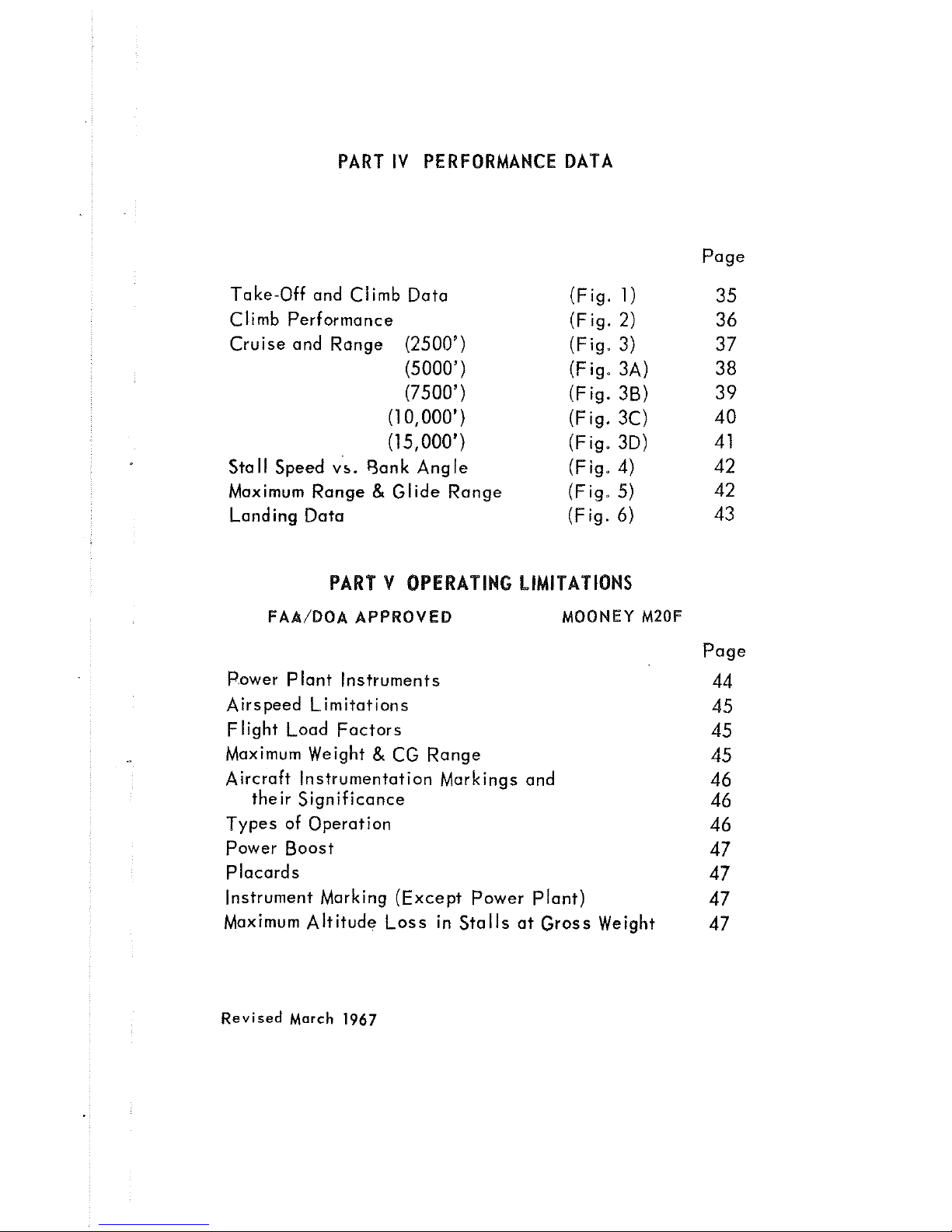
PART IV PERFORMANCE
DATA
Take-Off and Climb Data
Climb Performance
Cruise and Range (2500')
(5000')
(7500')
(1
0,000')
(1 5,000')
Stall Speed
vs.
Sank Angle
Maximum Range
&
Glide Range
Landing Data
(Fig.
1)
(Fig.
2)
(Fig. 3)
(Fig. 3A)
(Fig.
38)
(Fig. 3C)
(Fig. 3D)
(Fig.
4)
(Fig. 5)
(Fig. 6)
Page
PART V OPERATING
LIMITAT
IONS
FAA/BOAAPPROVED MOONEY
M20F
Page
Power Plant Instruments
Airspeed Limitations
Flight Load Factors
Maximum Weight
&
CG Range
Aircraft Instrumentation Markings and
their Significance
Types of Operation
Power Boost
Placards
Instrument Marking (Except Power Plant)
Maximum Altitude Loss in Stalls at Gross Weight
Revised
March
1967
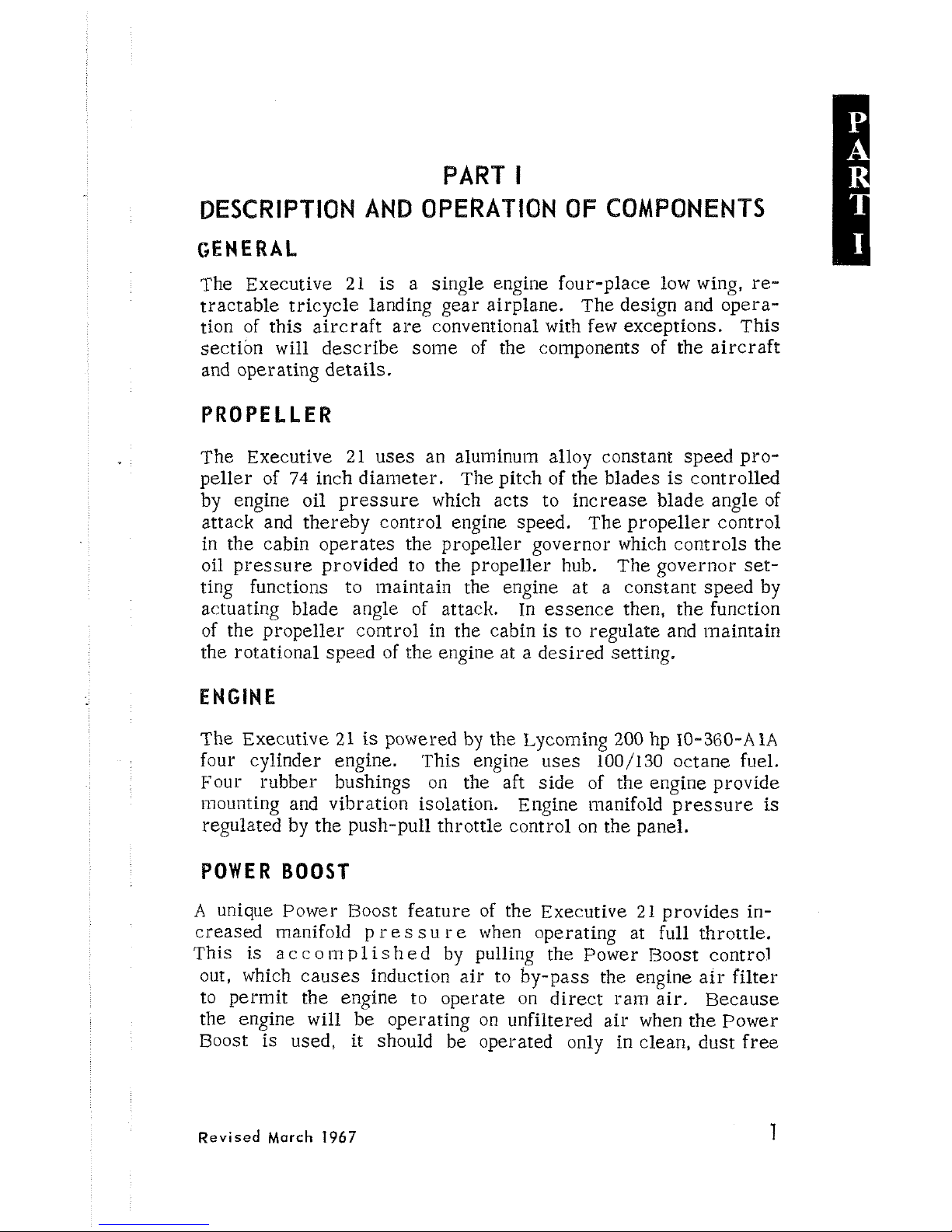
PART
I
DESCRIPTION AND OPERATION OF COMPONENTS
GENERAL
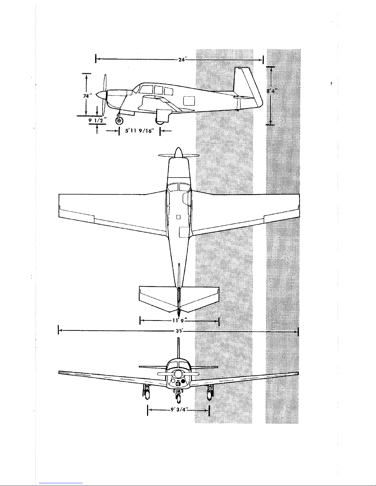
The Executive 21 is
a single engine four-place low wing, re-
tractable tricycle landing gear airplane.
The design and operation of this aircraft are conventional with few exceptions. This
section will describe
some of the components of the aircraft
and operating details.
PROPELLER
The Executive 21 uses an alunlinu~n alloy constant speed pro-
peller of
74
inch diameter. The pitch of the blades is controlled
by engine oil pressure which acts to increase blade angle of
attack and thereby control engine speed. The propeller control
in the cabin operates the propeller governor which controls the
oil pressure provided to the propeller hub. The governor
ser-
ting functions to maintain the engine at a constant speed by
actuating blade angle of attack. In essence then, the function
of the propeller control in the cabin is to regulate and maintain
the rotational speed of the engine at a desired setting.
ENGINE
The Executive 21 is powered by the Lyconling
200
hp
10-360-A
1A
four cylinder engine. This engine uses 100/130 octane fuel.
Four rubber bushings on the aft side of the engine provide
mounting and vibration isolation. Engine
~iianifold pressure
is
regulated by the push-pull throttle control on the panel.
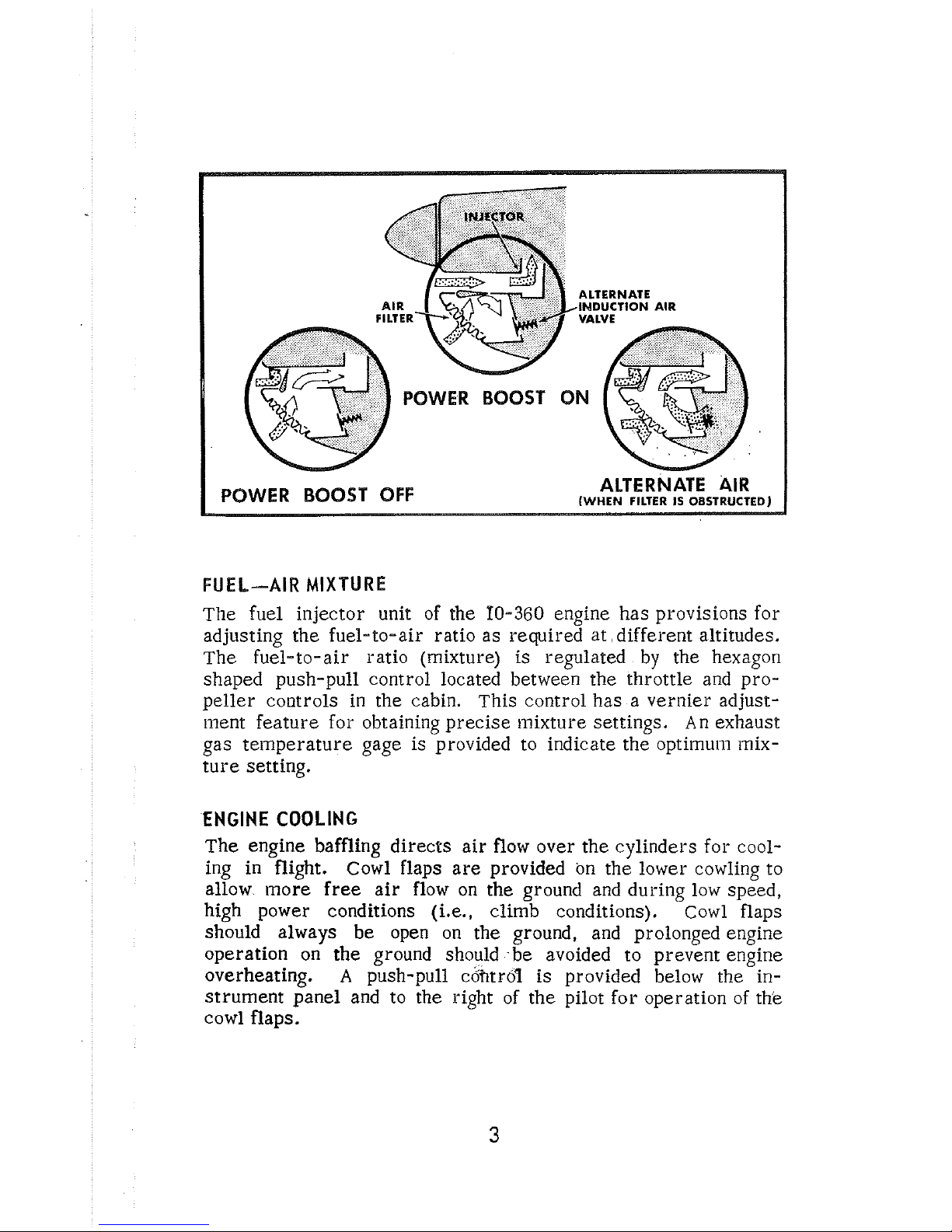
POWER
BOOST
A
unique Power Boost feature of the Executive 21 provides in-
creased
manifold p re
s s
u re when operating at full throttle.
This
is
a
c c o
111
p
1
is
h ed by pulling the Power Roost control
out, which causes induction air to by-pass the engine air filter
to
perinit the engine to operate
on
direct ram air. Because
the engine will be operating on unfiltered air when the Power
Boost is used,
it should be operated only in clean, dust free
Revised
March
1967
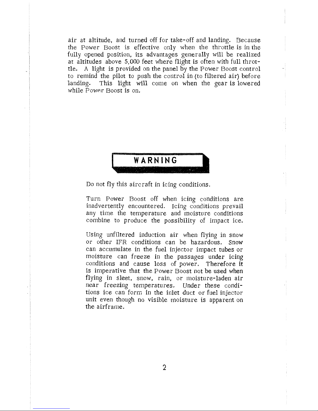
air at altitude, and turned off for take-off and landing.
Because
the Power Boost
is effective only when the throttle is in
the
fully opened position, its advantages generally will be realized
at altitudes above
5,000
feet where flight is often with full throt-
tle.
A
light is provided on the panel by the Power Boost control
to remind the pilot to push the control in (to filtered air) before
landing. This light will
come on when the gear
is
lowered
while Power Boost is on.
I
WARNING
Do not
fly
this aircraft in icing conditions.
Turn Power Boost off when icing conditions are
inadvertently encountered. Icing conditions prevail
any
time the temperature and inoisture conditions
coixbine to produce the possibility of impact ice.
Using unfiltered induction
air when flying in snow
or other
IFR
conditions can be hazardous. Snow
can accumulate in the fuel injector
impact tubes or
inoisture can freeze in the passages under icing
conditions and cause loss of power. Therefore it
is imperative that the Power Boost not be used when
flying in sleet, snow,
rain, or
i~~oisture-laden air
near freezing
teii~peratures. Under these condi-
tions ice can
for~li in the inlet duct or fuel injector
unit even though no visible moisture
is
apparent on
the
airframe.
POWER
BOOST
ON
FUEL-AIR
MIXTURE
The fuel injector unit of the
10-360
engine has provisions for
adjusting the fuel-to-air ratio as required at, different altitudes.
The fuel-to-air ratio (mixture) is regulated by the hexagon
shaped push-pull control located between the throttle and propeller controls in the cabin. This control has a vernier
adjustnlent feature for obtaining precise mixture settings. An exhaust
gas temperature gage is provided to indicate the
optiinurn mix-
ture setting.
ENGINE
COOLING
The engine baffling directs air flow over the cylinders for cooling in flight. Cowl flaps are provided on the lower cowling to
allow more free air flow on the ground and during low speed,
high power conditions
(i.e., climb conditions). Cowl flaps
should always be open on the ground, and prolonged engine
operation on the ground should be avoided to prevent engine
overheating.
A
push-pull cofitro'i is provided below the instrument panel and to the right of the pilot for operation of th'e
cowl flaps.
.ENGINE LUBRICATION
The engine has a pressure-type wet- sump lubrication system.
It has an eight quart capacity; however, as a general rule, when
the oil level drops below six quarts, one quart
is
added. This
will maintain the oil level between the six and seven quart level.
See Part
111 for type of oil used and time between oil changes.
An oil temperature thermostat, located in the oil reservoir,
is set for
180'
F.
to assure adequate operating engine oil tem-
peratures. The oil cooler is
mounted on the lower left side
of the cowling. An oil filter is available as optional equipment.
ENGINE IGNITION
The ignition system has the following features:
1.
Two Bendix magnetos, the left magneto being equipped with
a set of retard breaker points.
2.
A
starting vibrator, located on the upper firewall, which
furnishes a shower of sparks for starting.
3.
A
switch. which coinbines both ignition and starting functions.
4.
Shielded spark plugs and ignition harness to suppress radio
noises.
When the push-type starter switch is activated in the "start"
position, the starter vibrator sends an interrupted current
through the retard-breaker points while the right magneto
is
grounded out. The left magneto then provides a fixed retard and
a long duration, boosted spark for starting.
FUEL
SYSTEM
Fuel is carried
in
integral. sealed sections in the tront por-
tion of each wing root. Each tank will hold
32
gallons of aviation
gasoline
(100/130
octane\. An internally-mounted fuel quantity
indicator (effective
Dn
S/N
670074 & ON)
can be seen through
each fuel
tank filler neck. considering load and range requireinents. you lxay choose to fill each tank only to its 25-gallon
l~lark on the indicator. Tank vents allow ventilation as fuel is
depleted
and overflow when fuel expands in hot weather. The
fnel tanks each have a suinp drain under the wing from which
fuel
]nay be saillpled to check for water or sediment contamina-
tion.
A
small plastic cup with anactuator prong is provided to
obtain fuel
sa~nples.
If
water is present in the fuel, a distinct
line separating the
water from the gasoline may be seen through
the plastic cup. Water. being heavier, will be
on
the bottom
of the cup, and the light green colored fuel will be on top.
4
Revised
March
1967
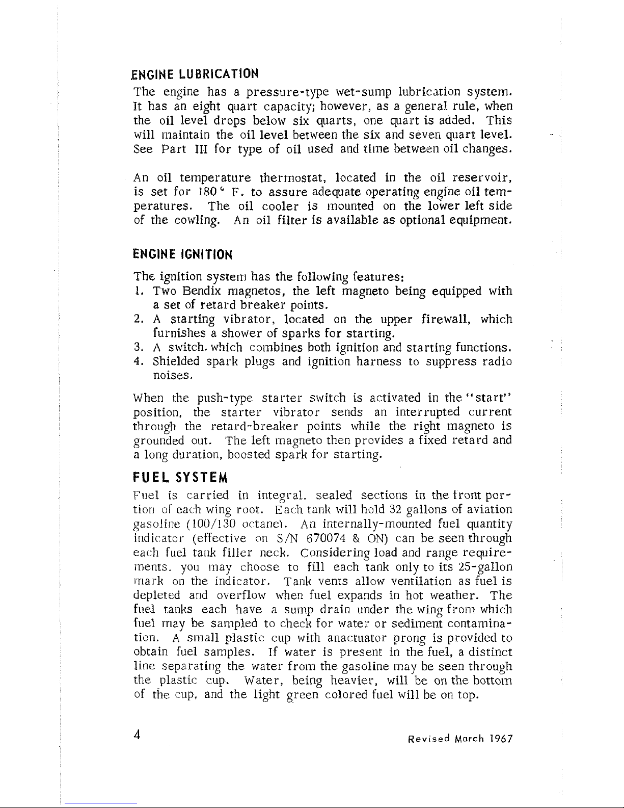
SAMPLING
FUEL
FROM MAIN TANKS
Aluminum fuel lines feed the fuel from the tank to a two-way,
positive-setting selector valve on the floor ahead of the pilot's
seat. The selector valve feeds fuel from one of the tanks at a
time, and also has an "off" position for extended periods of
storage or for emergency use. The selector valve also con-
tains a sump drain which
is
actuated by pulling the ring adjacent
to the fuel valve handle. Switch the selector valve handle to
the right and left tanks to drain the respective lines. Be sure
sump drain returns to normal closed position after releasing
the
.ring. Fuel is fed from the selector valve through the electric boost pump, then to the engine driven pump and into the fuel
injector unit. The electric boost pump
is
turned on for take-off
and landing to provide fuel pressure if the engine driven pump
inalfunctions.
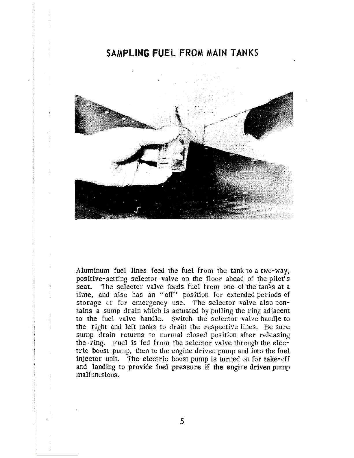
SELECTOR DRAIN VALVE
1
WARNING
Under no circutnstances should aviation fuel of a
lower grade than
100/130 octane be used. Aviation
fuels
1xay be distinguished by their color:
80
octane
is
red,
91
octane is blue, and 100 octane
is
green.
ELECTRICAL
SYSTEM
The electrical syscenl is provided with a 50-amp.,
12-volt
gen-
erator and a
35
amp - hour battery which is located aft of the
baggage compartment. All electrical systems can be turned
off by the
master switch which actuates a relay located at the
battery.
The inaster switch for the electrical system is located
at the left-hand side of the flight panel. The electrical system
operates all the electrical accessories listed below:
1.
Radios
2.
Engine starter
3.
Starter vibrator
4. Navigation lights and interior lights
5.
Landing light
6.
Rotatirig beacon (if installed)
7.
Heated pitot
(if
installed)
8.
Turn coordinator
9.
Cigarette lighter
10.
Electric landing gear (if installed)
1
1.
Fuel gages
12.
Electric fuel puinp
13.
Stall warning horn
14. Landing gear warning horn and warning lights
NOTE: The engine has its own separate electrical
systelil
and will continue to run, even though the ~naster
switch has been turned off. or even though the accessory electrical
system should malfunction.
Interior Lights
Panel
illu~nination is provided by two adjustable spot lights
mounted on the headliner and individual post lights for the instrument panel. These lights are controlled by a rheostat. The
fuel selector valve is
illuillinated by a small light lnounted under
the panel on the left side.
The intensity of this light is con-
trolled
by
rotating the lens housing.
Amineter
The ammeter in the engine instrument clustgr will indicate if
the battery is charging or
discWt-ging.
A
inalfunction in the
generator or voltage regulator will be shown
a3 an ammeter
discharge at flight power settings.
A
low battery will cause a
high charge indication.
Revised
March
1967
Electrical Panel
The electrical panel is divided into two parts:
a. The electrical toggle switches, on the lower left side of the
pilot's panel, act in combination both as on-off switches and
as breaker switches. Should any of these circuits be overloaded, the switch
auto~~~atically turns to the "ofP' position.
These switches are,
froin left to right:
1.
The electrical fuel puinp
2.
An optional equipment switch (Marker beacon)
3.
An optional equipment switch (Glide slope)
4.
An optional equipment switch (Pitot heat)
5. An optional equipment switch (Rotating beacon)
6.
The navigation lights
7.
The landing light
b. The breaker switches which are located on the lower right
side of the copilot's panel, are covered by a special breaker
switch cover. These switches are of the push-to-reset
type*
AIRFRAME
The structure of the Executive
21
is of conventional all-metal
design. The cabin section consists of tubular steel structure
covered with
alu~ninunl sheet metal. The center windshield
post and the
firewall are stainless steel.
'The wing, stabilizer, and fin have
a
11iain spar design and an
auxiliary spar with stressed skin to carry torsional loads.
?'he
tail cone is a conventional semi-monocoque design,
The seat
design features contoured construction. The front seats are
adjustable fore and aft and have adjustable three-position backs.
The rear seat back may be
retnoved for additional cargo space.
The entire empennage pivots around two attachment points to
the tail cone to provide stabilizer trim.
A
screw
mechanism
actuates the empennage movement at the rear bulkhead when
the
trim control wheel is operated.
Revised
March
1967
LANDING
GEAR
Manual Systern
The landing gear is unique in that it is manually retracted by
the pilot by
means of a lever in the cabin.
The systein is op-
erated by direct mechanical linkage and has proven to be one
of the
most reliable and maintenance-free retraction systeins
available. An electrically powered landing gear retractipn systen1 is also available at extra cost and is described in the following section.
The
inanual system is aided
by
bungee type springs in the fuselage and assist springs in the wing, which balance the weight of
the gear.
~ubber discs are used for shock absorption in the
welded steel tube gear structure. Grease fittings are provided
at certain
iinportant lubrication points on the landing gear.
The position of the gear is indicated by lights on the panel which
will warn of an unlocked condition. These lights
may be dinllned
by rotating the lens housing to prevent glare at night. Press the
lens housing in to test the bulbs. The red indicator light will
coine
on if the handle on the retraction lever is not sufficiently engaged in the down and locked position, thereby indicating
an unsafe-to-land condition. The green light indicates that the
handle is
properly engaged in the down position, and the gear
is in the landing configuration.
A
thumb operated latch
is
provided on the down socket to prevent unlocking of the gear when
it is down unless it is deliberately released.
To retract the gear, depress the safety latch button and slide
the gear handle
fro111 the down-lock socket.
Move the handle
rapidly to the
floor between the seats.
Slide the gear handle
into the up-lock socket, and the operation is complete. The
more rapid the lnovernent of the handle, the easier it is to re-
tract the gear. The gear retracts easiest at low airspeeds.
To lower the gear, slide the gear handle
from the up-lock socket
and
move the handle forward to the instrument panel. Slide the
gear handle into the down-lock socket and check the gear warning
light for a gear-down indication (a green light).
Electrical Gear Systein (optional)
The optional electrical landing gear retraction
systetn is operated by the wheel-shaped switch on the upper portion of the
flight panel. To raise the gear, the knob is pulled out and the
switch moved up to its upper detent. An "airspeed switch" is
incorporated in the electrical circuit which prevents landing
gear retraction until a safe airspeed is attained.
Never rely on the airspeed safety switch to keep
the gear extended while taxiing, taking off or landing.
Always check the gear switch for the down position.
A
litilit switch will stop the gear in its retracted position; the
gear-up light will coine on, and the gear switch will require no
further attention until landing. To lower the landing gear, the
knob is pulled out,
~noved down, and placed in the lower detent.
A
liinit switch will stop the gear system when the proper locking force has been exerted to hold the gear down, and the green
gear-down-light will come on.
A
discharged storage battery lnay prevent the land-
ing gear
fro111 fully extending.
There are three ways to check that the gear is completely down
and locked:
1.
The green "safe-to-land" indicator light (on the left panel)
will
coine on.
2.
The black indicator marks, as seen through the glass in the
floorboard, will be aligned.
3.
Retard throttle fully, and if no warning horn is heard the
gear should be down and locked. The gear warning horn
eniits an interrupted sound of a different pitch than the stall
warning horn.
When these conditions are fulfilled, the aircraft inay be landed
with no further attention to the landing gear
syste~i~.
 Loading...