

Mooney Ranger M20C, 20-1147 Operator's Manual
MOONEY
OPERATORS MANUAL
MODEL
M2OC
SERIAL NUMBERS
20-1 147
&
ON
DECEMBER
1974
ISSUE
MOONEY AIRCRAFT CORPORATION
KERRVILLE, TEXAS
78028
m
MANUAL NUMBER
74-20C-O~-~
G#

LOG
OF
PAGES
Page
ONLY
the pages listed herein are applicable
to Model M20
C.
Serial Numbers
Date
..........
Title
12/2/74
............
i
12/2/74
............
ii
12/2/74
............
iii
12/2/74
............
iv
12/2/74
SECTION
I
Page
Date
SECT ION
I
I
Page Date
...........
2-1 12/2/71
...........
2-2 12/2/74
...........
2-3 12/2/74
...........
2.4 12/2/74
...........
2.5 12/2/74
...........
2.6 12/2/74
...........
2-7 12/2/74
...........
2-a 12/2/74
...........
2-9 12/2/74
..........
2- 10 12/2/74
..........
2-11 12/2/74
..........
2-12 12/2/74
..........
2-13 12/2/74
..........
2-14 12/2/74
.......
..
2-15
0,
12/2/74
..........
2-16 12/2/74
..........
2-17 12/2/74
..........
2-18 12/2/74
SECTION
Ill
Page Date
..........
3-1 12/2/74
..........
3-2 12/2/74
3-4
..........
12/2/74
3-5
..........
12/2/74
..........
3-6 12/2/74
3-7
..........
12/2/74
3-8
..........
12/2/74
3-9
..........
12/2/74
..........
3- 10 12/2/74
..........
3-
11
12/2/74
..........
3-12 12/2/74
.
..........
3 13 12/2/74
..........
3-14 12/2/74
..........
3- 15 12/2/74
3-6
..........
12/2/74
..........
3- 16 12/2/74
.
..........
3 17 12/2/74
..........
3-18 12/2/74
..........
3-19 12/2/74
..........
3-20 12/2/74
3-21
..........
12/2/74
..........
3-22 12/2/74
3-23
..........
12/2/74
3.24
..........
12/2/74
3-25
..........
12/2/74
3-26
..........
12/2/74
SECTION
1V
(FAA
APPROVED)
Page Date
4-1
..........
12/2/74
4- 2
..........
12/2/74
4-3
..........
12/2/74
4-4
..........
12/2/74
4-5
..........
12/2/74
4-6
....
.,
.....
12/2/74
.
4 7
..........
12/2/74
4-8
..........
12/2/74
4-9
..........
12/2/74
4-10
.........
12/2/74
LOG
OF
PAGES (CONT.)
SECTION
V
(FAA
APPROVED)
Page
Da
f
e
SECTION
VI
Page
Date
SECTION
VII
/
Page
Date
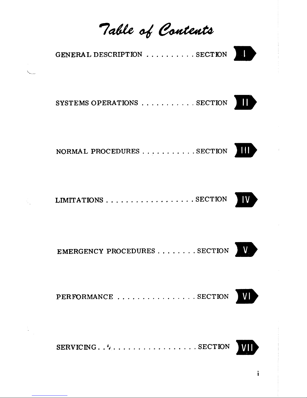
GENERAL DESCRIPTION
..........
SECTION
SYSTEMS OPERATIONS
...........
SECTION
NORMAL PROCEDURES
...........
SECTION
..................
LIMITATIONS SECTION
........
EMERGENCY PROCEDURES SECTION
................
PERFORMANCE SECTION
.................
SERVICING.
.4
SECTION
This manunl is issued as your operating guide for the
Vooney IIANGEIt. It is important that you--regardless
of
your
previous experience-- carefully read the hand-
boolc
from
cover to cover and review
it
frequently.
IMPORTANT: THIS MANUAL CONTAINS Federal
Aviation Administration APPROVED LIMITATIONS
AND MUST
I'IE CARRIED
IN
THE
AIRCRAFT AT
ALL, TIMES.
All
~~ilormation :incl illustrations in this manual are based
on the latest procluct information available at the time of
1)ut)lic~ttion al)provnl.
'The right is reserved to ~nalce
cliangcs :it any
tillic
without notice.
Every
etfort has been
m:itle 1 o
present the material
in
;L
clc:ir
ancl
convenient
ni:lnllrr to c~iablc you to use the m;i~iii:~l
:is
:I
ready ore-
sent:~tion :incl (*ontent recommenclations is solic.itec1.
Mooney warrants each Aircraft (which includes
its
accessories and equipment) sold hereunder,
to be free from defects in materialand
workmanship under normal use and service when operated
in accordance with Mooneyfs operating instruc-
tions during the period of six
(6)
montlls following
delivery of the Aircraft to
the original retail pur-
chaser or
the first user or during the period of
one
(1)
year follo~ving the date of issue of the original airworthiness certificate for the Aircraft,
whichever
period
fir
st terminates. Mooney does
not
malie ally warranties with respect to equipment
-
and accessories not manufactured by Mooney but
Mooncy assigns
Gny owner of sucll Aircraft (to
the extent same may be assignable) any warra~ities
Mooney has receivecl from the
manufacturers
of
such
ecluipment
ancl
accessories and will,
on
request, provide and execute such instruments as may
be reasonably required to evidence such assignment.
Mooneyfs
obligztion under this warranty
is
limited
to repairing or replacing, at Mooney's option, any
part or parts
which within the applicable warranty
period set forth above, shall be returned, transportation charges prepaid, to Mooney's plant in
Kerrville, Texas or to such other location designated by Mooney, and which upon examination, shall
disclose to Mooney's satisfaction that such part is
defective.
A
new warranty period is not established
for parts replaced hereunder. Parts replaced hereunder are warranted for the remainder of the original
warranty periocl applical~le to Aircraft solcl hereunder.
The
repair or replacement of defective parts under
this warranty shall
be macle by Mooney without charge
for the parts, or
labor for removal, installation and/
or actual
repair of defective parts.
5,
This warranty does not apply to Aircraft, equipment,
accessories, or other parts manufactured or sold by
Mooney which have been subject to misuse, negligence,
accident or improper installation, or
which"1ave been
repaired or altered outside of Mooney's plant in a
way which, in the opinion of Mooney, adversely
affects its performance or reliability. Further, this
warranty does not include
norinal maintenance services (such as engine tune-up, cleaning, control rigging, brake and other mechanical
adjustn~ents,
n~aintenance inspections, etc. ) and the replacelllent
of service items (such as sparlr plugs, brake linings,
filters,
hoses, belts, tires, etc. ) nlade in connection
with such services or required as maintenance,
nor
to normal deterioration of soft trim and appearance
itellis (such as, paint, upholstery, rubber-like items,
etc. ) clue to wear anct exposure.
This warranty shall extend to any owner (hereafter
"Owner") of the Aircraft
making claiill within the
specified warranty period.
THIS WARRANTY BY IdIOONEY IS tIADE EXPRESSLY IN
LIEU OF ANY OTHER P'ARRANTIES EXPRESSED OR
IIIPLIED IN FACT OR BY LAW, INCLUDING ANY IIIPLIED
WARRANTY OF MERCHANTABILITY OR FITNESS FOR A
PARTICULAR PURPOSE, AND IS IN LIEU OF ANY
OTHER
OBLIGATION OR LIABILITY CPJ THE PART OF iiOONEY
TCI ANYONE OF ANY NATURE PIHATSOEVER BY REASON OF
THE
IIANUFACTURE
AND/OR
THE
SALE
AND/OR
THE
USE
OF SUCH AIRCRAF1 , 1100NEY SHALL IN NO E'JENT BE
LIABLE TO ANY OWNER OR TO ANY OTHER PARTY OR
PARTIES FOR SPECIAL, INCIDENTAL OR
CONSECUEN-
TIAL LOSS OR DAiiAGES OR FOR
ANY
OTHER LOSS OR
DAMAGE
TO
PROPERTY
AND/OR INJURY
OR
DEATH
TO
PERSONS OTHER THAN FOR THE PROPERTY DAliAGE TO
SUIIJECT AIRCRAF r PROXIMAl-ELY RESULT
I
I'JG
FRO/, ANY
BRtACH BY MOONEY OF THE AFORESTATED l.!ARRANTYt
IIOONEY NEITHER ASSUMES NOR AUTHORIZES BU'IER OF
ANYONL ELSE TO ASSUllE FOR IT ANY OBLIGATION OR
LIABILITY IN CONNECTION WITH THE AIRCRAFT SUBJECT HEREOF, OTHER THAN THOSE EXPRESSLY SET OUT
HEREIN, NO BILL OF SALE OR TRANSFER OF TITLE
TO THIS AIRCRAFT SHALL NULLIFY THE PROVISIONS
HEREOF,
SECTION
I
.
GENERAL
DESCRIPTION
DESIGN
FEATURES
AIRFRAME
...........................
1.
2
POWERPLANT
........................
1-2
FLIGHT CONTROLS
.....................
1.
3
LANDING
GEAR
.......................
1.
3
SPECIFICATIONS OUTLINE
POWERPLANT
........................
1-3
PROPELLER
.........................
1-4
LANDING
GEAR
......................
-1-4
FUEL & OIL
.........................
-1-5
WEIGHT
&
LOADING
...................
-1-5
BAGGAGE
COMPARTMENT
..............
-1-5

MANUAL
DESIGN
FEATURES
The MOONEY RANGER (M20C) is a low-wing four-
place aircraft with a retractable gear.
A
fourcylinder engine powers the aircraft for economical,
high-performance flight. Licensing under Federal
Aviation Administration regulations assures that
your
Mooney meets the requirements of Normal Category
aircraft.
AIRFRAME
The airframe has a welded, tubular-steel cabin structure enclosed in sheet-aluminum skins. Stressed skins
rivet to main and auxiliary spars in the wing, stabilizer,
and vertical fin. The laminar-flow wing has full wraparound skins with flush riveting over the forward top
two thirds of the wing area.
For pitch trim control, the empennage pivots on the aft
fuselage. A torque-tube-driven jack screw, bolted to
the rear
tail con^
bulkhead, sets the stabilizer angle.
The forward-opening cabin door provides access to both
front and rear seats. The baggage compartment door is
above the wing trailing edge to enable baggage loading
from the ground.
POWER PLANT
The
powerplant is a four-cylinder air cooled engine that
develops 180 horsepower.
A
60-ampere 12-volt alterna-
tor supplies ample electrical power for all standard and
optional equipment at all engine speeds
from warmup to
flight power settings.
The hydraulic propeller governor, using oil pressure for
increasing blade pitch to control engine speed, regulates
the controllable-pitch constant-speed propeller. Spring
and blade aerodynamic forces decrease blade pitch.
FLIGHT
CONTROLS
Conventional dual controls link to the control surfaces
through push-pull tubes. The co-pilot's rudder pedals
are removable.
The Mooney Positive Control (P. C.
)
system
is
standard
equipment.
P.
C.
is
a lateral stability augmentation system that provides a high degree of roll and yaw stability,
thereby enhancing the inherent wings-level flight characteristics of the aircraft. The system works full time
from takeoff through landing but can be easily deactivated
or overpowered for flight maneuvers.
P.
C . allows you,
the pilot, to devote more time to navigation, traffic surveillance, and communications.
LANDING
GEAR
The tricycle landing gear allows maximum taxi vision and
ground maneuvering.
Hydraulic disc brakes and a
steer-
able nose wheel aid in positive directional control during
taxiing and crosswind landings.
The landing gear is electrically actuated. A gear warning
horn along with red and green position lights
help
prevent
inadvertent gear-up landings.
The retraction
syste11l in-
corporates
a
squat switch that prevents gear retraction un-
til a safe airspeed is attained. An emergency gear extension system is provided.
SPECIFICATIONS OUTLINE
POWER
PLANT
TYPE : Four- cylinder, air cooled, horizontally opposed,
$4
*
x,~~~~~
e-
OPERATORS MANUAL
and carbureted engine with a wet-sump hubricating
system.
.......
Model (Lycoming). 0-360-AID
Rated Horsepower
@
2700 RPM
. .
180 BHP
.............
Bore 5.125 IN.
............
Stroke 4.375 IN.
.......
Displacement 361.0
CU.
IN.
........
Compression Ratio 8. 7:l
...
Carburetor, Marvel-Schebler MA-4-5
...
Magnetos, Scintilla S4LN-200 Serie
PROPELLER
TYPE : Constant-speed, hydraulically controlled
propeller with a single-acting governor.
Model (Hartzell)
...
HC-C~YK-
1B/7666 A-2
............
Diameter. 74 IN.
Blade Angle
(@
30 IN. STA)
:
............
Low 130 + 0°
............
High 2g0+20
-
LANDING GEAR
TYPE:
Electrically retracted tricycle gear with rub-
ber
shock discs, steerable nose wheel, and hydraulic
disc brakes.
.......
WheelBase 5FT6-9/16IN.
........
Wheel Treaci
9
FT 3/4 IN.
Tire Size
:
.............
Nose 5.00~ 5
............
Main. 6.00~ 6
Tire Pressure:
..............
Nose 30 PSI
Ma
..............
30 PSI
*
-~~ONEV
OPERATORS
MANUAL
FUEL
&
OIL
Usable Fuel Capacity
.......
52 GAL
Minimum Fuel Octane Rating
(aviation grade)
........
91/96
Oil Capacity
(6
QTS
MIN
for flight)
.
8
QTS
WEIGHT
&
LOADING
Gross Weight
..........
2575 LBS
Approximate
Einpty Weight
(with standard equipment)
...
1525 LBS
Useful Load
...........
1050 LBS
Wing Loading
@
Gross Weight
.
.
15.1
PSF
Power Loading
@
Gross Weight
. .
14.3
PHP
BAGGAGE COMPARTMENT
Maximum Baggage Loading (unless limited
by
weight envelope)
.........
120 LBS
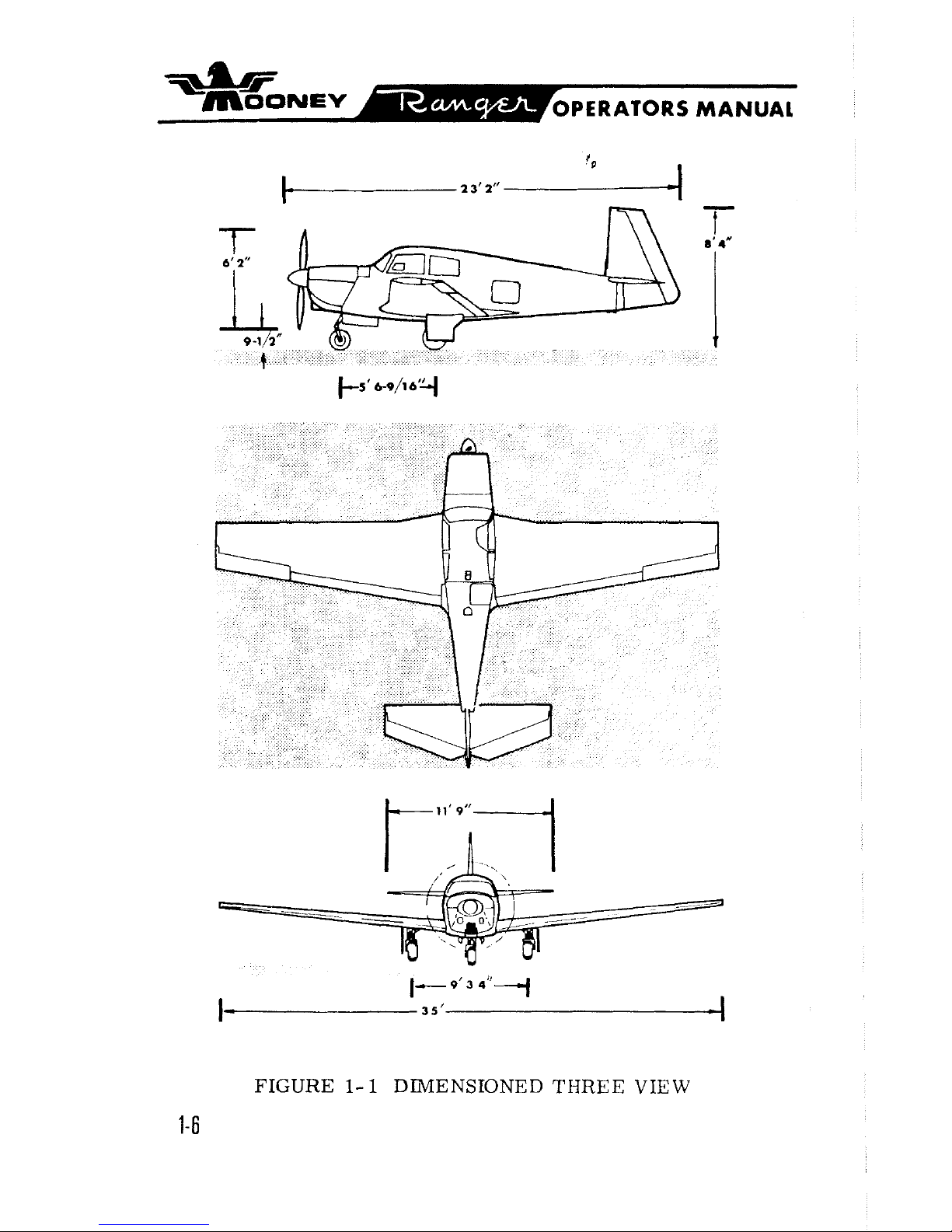
FIGURE
1- 1
DIMENSIONED THREE VIEW
1-6
SECTION
II
.
SYSTEMS
OPERATIONS
POWER
PLANT
.....................
ENGINE CONTROLS 2-4
.....................
IGNITION SYSTEM 2-5
.......................
FUEL SYSTEM 2-5
.........................
OIL
SYSTEM 2-6
ENGINE COOLING
.....................
2-6
.....................
VACUUM SYSTEM 2-6
INSTRUMENTS
.................
FLIGHT INSTRUMENTS 2-7
FLIGHT CONTROLS
............
PRIMARY FLIGHT CONTROLS 2-8
POSITIVE CONTROL
...................
2-9
TRIM CONTROLS
.....................
2-10
WING FLAP CONTROLS
.................
2-10
LANDING GEAR
ELECTRIC GEAR RETRACTION SYSTEM
.....
2-11
EMERGENCY GEAR EXTENSION SYSTEM
.....
2-12
BRAKE
&
STEERING SYSTEMS
............
2-12
ELECTRICAL POWER
ALTERNATOR & BATTERY
...............
2-12
CIRCUIT BREAKERS
...................
2-13
ANNUNCLATOR LIGHTS
.................
2-15
INSTRUMENT
&
PLACARD
LIGHTS
.........
2-16
CABIN LIGHTING
.....................
2-16
CABIN ENVIRONMENT
HEATING & VENTILATING SYSTEMS
........
2-16
WINDSHIELD DEFROSTING SYSTEM
........
2-17
CABIN
SEATS
&
SAFI~Y
BELTS
................
2-18
BAGGAGE
&
CARGO AREAS
..............
2-18
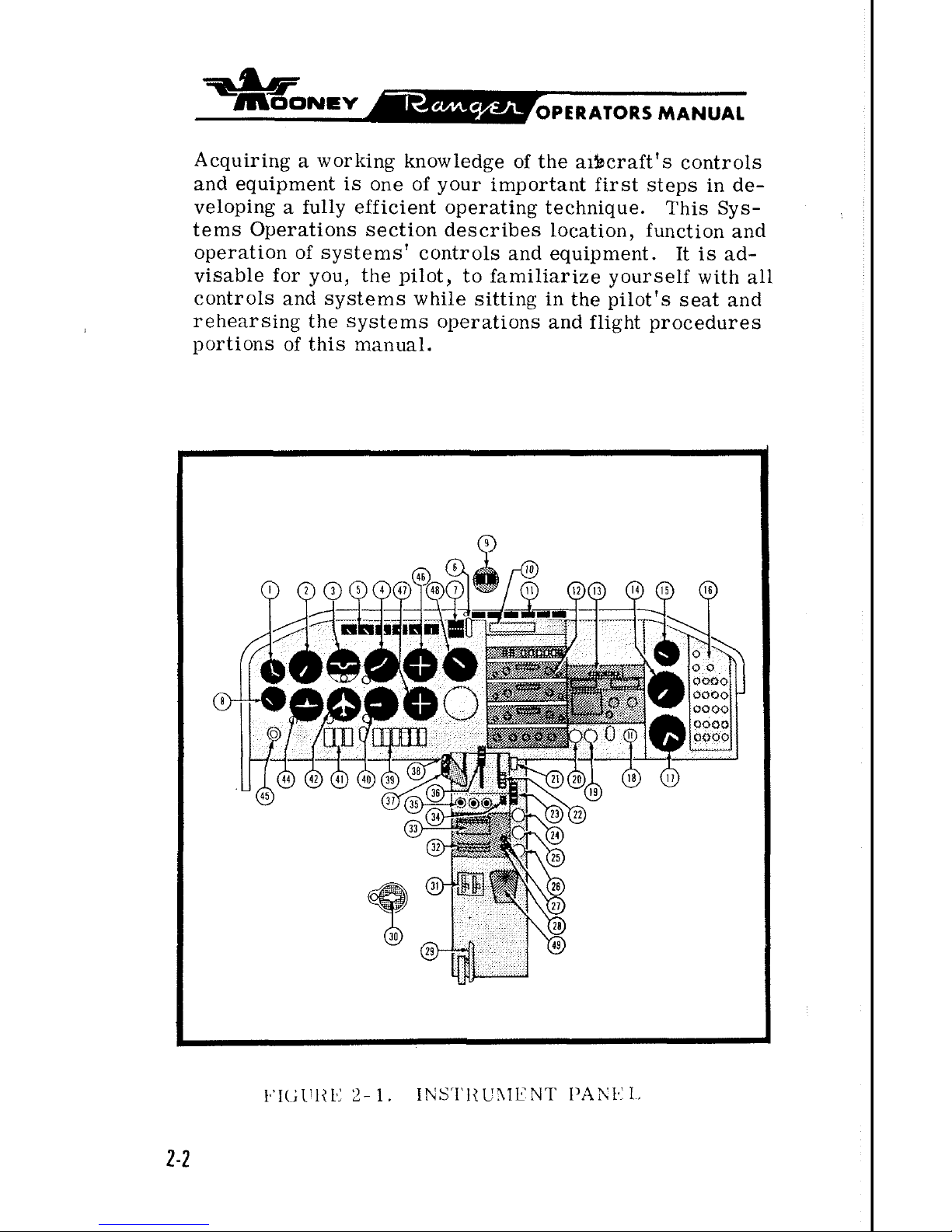
Acquiring a working knowledge of the aibcraft's controls
and equipment is one of your important first steps in developing a fully efficient operating technique. This Sys-
tems Operations section describes location, function and
operation of systems' controls and equipment. It is advisable for you, the pilot, to familiarize yourself with all
controls and systems while sitting in the pilot's seat and
rehearsing the systems operations and flight procedures
portions of this manual.
-
moo~evE
OPERATORS MANUAL
POWER
PUNT
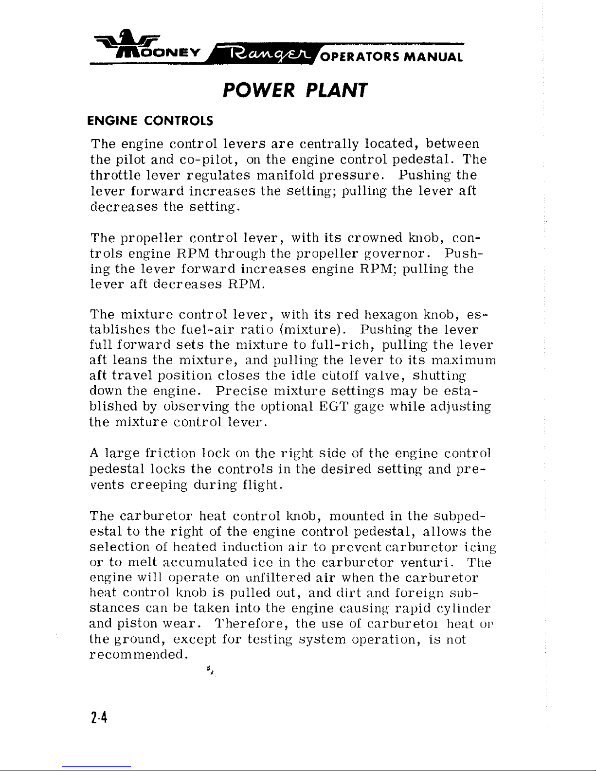
ENGINE CONTROLS
The engine control levers are centrally located, between
the pilot and co-pilot, on the engine control pedestal. The
throttle lever regulates manifold pressure. Pushing the
lever forward increases the setting; pulling the lever aft
decreases the setting.
The propeller control lever, with its crowned
knob, controls engine RPM through the propeller governor. Pushing the lever forward increases engine
RPM:
pulling the
lever aft decreases RPM.
The mixture control lever, with its red hexagon knob, es-
tablishes the fuel-air ratio (mixture). Pushing the lever
full forward sets the mixture to full-rich, pulling the
lever
aft leans the mixture, and pulling the lever to its maximum
aft travel position closes the idle cutoff valve, shutting
down the engine. Precise mixture settings may be established by observing the optional
EGT
gage while adjusting
the mixture control lever.
A
large friction lock on the right side of the engine control
pedestal locks the controls in the desired setting and pre-
vents creeping during flight.
The carburetor heat control knob, mounted in the
subped-
estal to the right of the engine control pedestal, allows the
selection of heated induction air to prevent carburetor
icing
or to melt accumulated ice in the carburetor venturi. The
engine will operate on unfiltered air when the carburetor
heat control
knob
is pulled out, and dirt and foreign sub-
stances can
l-te
taken into the engine causing rapid cylinder
and piston wear. Therefore, the use of
carburetoi heat o13
the ground, except for testing system operation, is not
recommended.
',
-ar
~sJONE~
OPERATORS
MANUAL
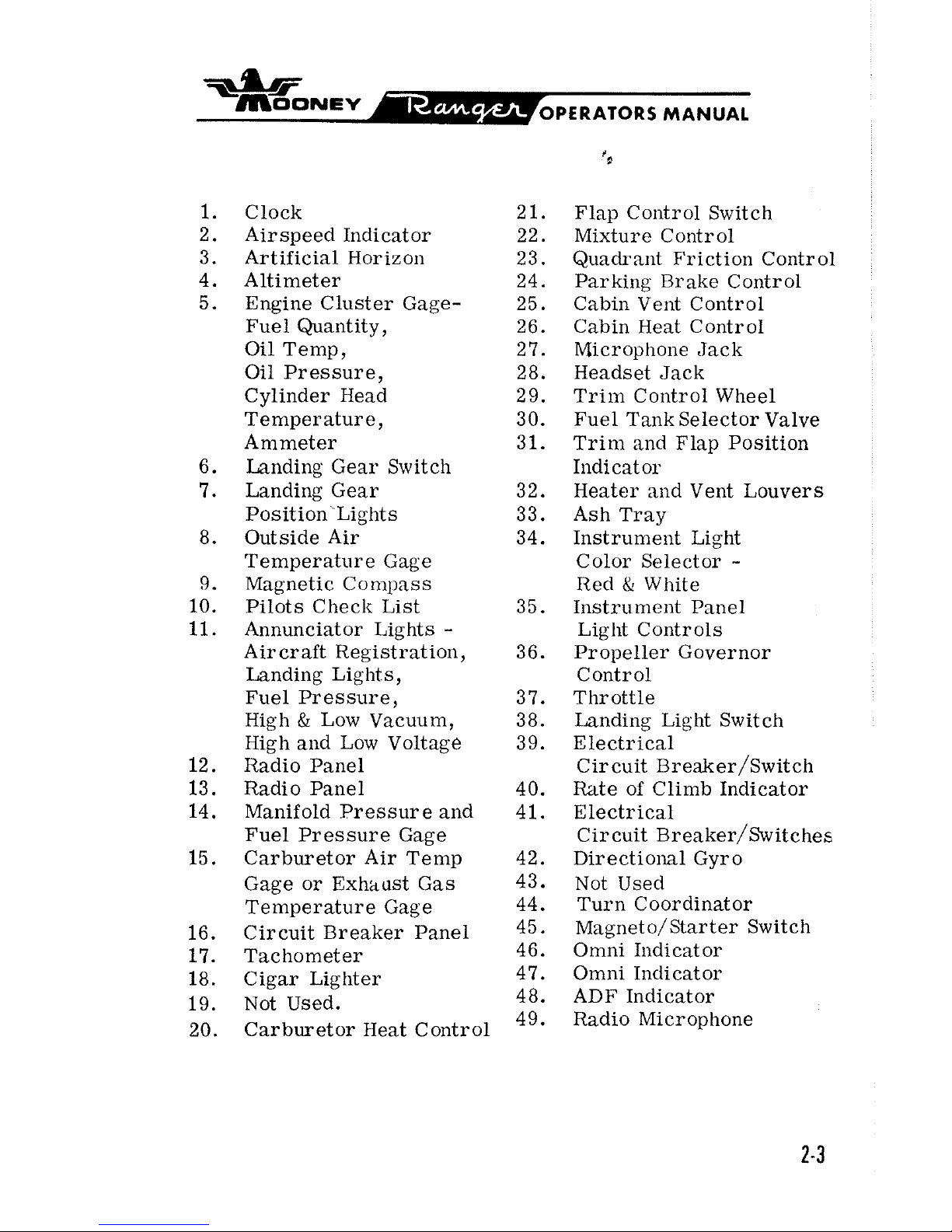
Clock 21.
Airspeed Indicator 22.
Artificial Horizon
23.
Altimeter 24.
Engine Cluster Gage- 25.
Fuel Quantity, 26.
Oil Temp,
2
7.
Oil Pressure, 28.
Cylinder Head
2
9.
Temperature, 30.
Ammeter 31.
Landing Gear Switch
Landing Gear 32.
Position Lights 33.
Outside Air 34.
Temperature Gage
Magnetic
Conlpass
Pilots Checlr List 35.
Annunciator Lights
-
Aircraft Registration, 36.
Landing Lights
,
Fuel Pressure, 3 7.
High
&
Low Vacuum, 38.
High
and Low Voltage 39.
Radio Panel
Radio Panel 40.
Manifold Pressure
and 41.
Fuel Pressure Gage
Carburetor Air Temp 42.
Gage or Exhaust Gas 43.
Temperature Gage 44.
Circuit Breaker Panel
45.
Tachometer 46.
Cigar Lighter 47.
Not Used. 48.
Carburetor Heat Control
49.
Flap
Contr 01 Switch
Mixture Control
Quadrant Friction Control
Parking Brake Control
Cabin Vent Control
Cabin Heat Contr
01
Microphone Jack
Headset Jack
Trim Control Wheel
Fuel
Tank Selector Valve
Trim and Flap Position
Iildicat or
Heater
and Vent Louvers
Ash Tray
Instrument Light
Color Selector
-
Red & White
Instrument Panel
Light Controls
Propeller Governor
Control
Throttle
Landing Light Switch
Electrical
Circuit
~reaker/~witch
Rate of Climb Indicator
Electrical
Circuit
~reaker/~witches
Directional Gyro
Not Used
Turn Coordinator
Magneto/Starter Switch
Omni Indicator
Omni Indicator
ADF Indicator
Radio Microphone
-
~OONEV
OPERATORS MANUAL
All engine instruments except the EGT gage, tachometer and fuel and manifold pressure gages are grouped
in the left instrument panel. Color arcs on instrument
faces mark operating ranges.
Proper interpretation of
engine instrument readings
is
essential for selecting
optimum contr
01 settings and for maintaining maximum
cruise fuel economy.
Engine limitations are given in
Section
IV.
IGNITION SYSTEM
The left magneto has a set of fixed retard breaker points
that aid in smoother, easier starting. A battery-powered
starting vibrator supplies a long-duration, boosted spark.
The starter-ignition switch, mounted on the left of the instrument panel, combines both ignition and starting functions. Turning the ignition key clockwise through
R,
L,
and BOTH to the START MAG position and then pushing for-
ward on the key and receptacle engages the starter. Re-
leasing the key when the engine starts allows the switch to
return by spring action to the BOTH position.
For safety,
the starter-ignition switch must be left at OFF when the
engine is not running.
FUEL
SYSTEM
Two integral sealed sections carry the fuel in the forward
inboard area of the wings.
Full fuel capacity
is
52
gallons.
There are sump drains
at
the lowest point in each tank for
taking fuel samples to check for sediment contamination
and condensed water accumulation.
Section VII discusses
the fuel sampling procedure.
The .recessed three-position fuel selector handle on the
cabin floor sets the selector valve below the floorboard
for LEFT tank, RIGHT tank, or the OFF position. The
fuel selector
va%e assembly contains a valve for draining
condensed water and sediment from the lowest point in the
=.LIF
~OONEV
OPERATORS
MANUAL
fuel lines before the first flight of the da~ and after
each refueling. Section
VII discusses the selector
valve flushing procedure.
Fuel feeds from one tank at
a
time to the selector valve
and through the electric fuel pump
enroute to the enginedriven pump and the carburetor unit. Electric fuellevel transmitters in the tanks operate fuel gages in the
engine cluster. The master switch actuates the fuel
quantity indicator system to maintain an indication of
fuel remaining in each tank.
The fuel pressure gage
registers fuel pressure in the line to the carburetor.
Vents in each fuel tank allow for overflow ventilation.
OIL SYSTEM
The engine has a full-pressure wet-sump oil system with
an
8
quart capacity. The automatic bypass control valve
routes oil flow around the
,oil cooler when operating tem-
peratures are below normal or when the cooling radiator
is
blocked.
The engine oil should be kept at
6
to 8 quarts.
Lycoming
Service Instruction
1014
(latest revision) gives recom
-
mended oil specifications and oil change intervals.
ENGINE COOLING
The down-draft engine cooling system provides ground
and
inflight power plant cooling.
Engine baffling directs
air
over and around the cylinders and out the cowl flap
openings.
Cowl flap doors are fixed in
a
position that
allows proper air flow on the ground and in flight.
VACUUM
SYSTEM
An engine-driven vacuum pump supplies suction for the
vacuum-operated gyroscopic flight instruments and the
MANUAL
Mooney Positive Control system. Air entering the
vacuum-powered instruments is filtered; hence,
sluggish or erratic operation of vacuum-driven instruments may indicate that a clogged vacuum filter element
is
preventing adequate air intake.
The vacuum an-
nunciator light will illuminate steadily for
Hi
Vac
and flashes for Laow Vac indication.
INSTRUMENTS
FLIGHT INSTRUMENTS
All
primary flight instruments are grouped on the shockmounted flight panel directly in front of the pilot's seat.
Optional gyro instruments may be installed in the standard
T-grouping with the attitude gyro at top center and the
directional gyro immediately below. The standard airspeed
indicator and sensitive altimeter cross the
"T".
The stan-
dard turn coordinator and optional vertical speed indicator
at
left of center complete the flight instrumentation.
The magnetic compass
is
mounted on the windshield post
above the instrument panel. A remote indicating gage is
installed in the left of the flight panel. There
is
space
and lighting for four optional radio indicators on the right
side of the flight panel.
&bF
~OONEV
PERATORS
MANUAL
A
pitot tube, mour~ted on the lower surfaw of the left
wing, picks up airspeed indicator ram air.
A
heated
pitot prevents pitot tube icing when flying in moistureladen air. A drain valve is located on the forward
bottom skin of the left wing just outboard of the wing
fillet. Static ports on each side of the tail cone supply
static air pressure for the altimeter, the airspeed
indicator, and the vertical speed indicator. A drain
valve is located on the fuselage bottom skin below the
tail
cone access door.
An alternate static
pressure
source valve will
be
found under the left side of the
flight panel.
A
stall warning horn, mounted in the cabin head liner
and triggered by a sensing vane on the left wing leading
edge, will sound when airspeed drops to near stall
speed. The sound becomes steady as the aircraft
approaches a complete stall.
There are two landing gear position lights; one is a green
GEAR
DOWN' light and the other is a red IN-TRANSIT light.
No, light shows when the gear is full up. Inadvertent posi-
tioning of the gear switch to the up position while the air-
craft is on the
ground will cause both the red and green
to
be
illuminated and the warning horn to souild if the
throttle is closed.
FLIGHT
CQNTROLS
PRIMARY FLIGHT CONTROLS
Push-pull tubes with self-aligning rod end bearings actuate
the primary flight control surfaces. Beveled aileron trail-
ing edges help reduce pilot control forces required for flight
maneuvering.
A
springloaded interconnect device indirectly joins the
aileron and rudder control systems to assist in
lateral stability during
flight maneuvers. Control
surface gap seals minimize airflow through the
hinge slots and reduce
drag.
MAP
LIGHT
SWITCH
I'
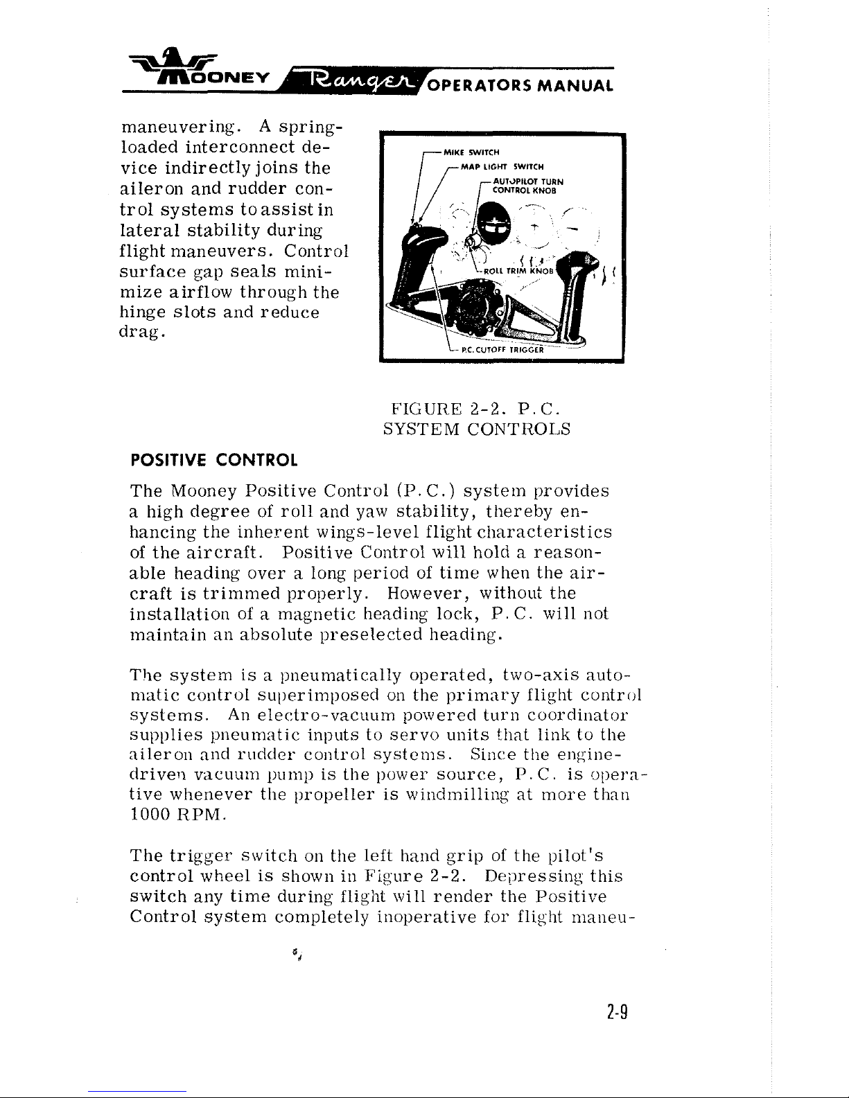
FIGURE
2-2.
P.C.
SYSTEM CONTROLS
POSITIVE CONTROL
The Mooney Positive Control (P.
C.)
system provides
a high degree of roll and yaw stability, thereby en-
hancing the inherent wings-level flight characteristics
of the aircraft.
Positive Control
will
hold a reason-
able
heading over a long period of time when the air-
craft is trimmed properly.
However, without the
installation of
a
magnetic heading lock, P. C. will not
maintain an absolute preselected heading.
The system
is
a pneumatically operated, two-axis auto-
matic control
sul)erimposecl on the primary flight control
systems.
An
electro-vacuum powered turn coordinator
supplies pneumatic inputs to servo units that link to the
aileron
and rudder control systems. Since tlte engine-
clrivert vacuum
pump
is the power source,
P.
C.
is opera-
tive whenever the propeller
is
windmilling at more than
1000
RPM.
The trigger
switch on the left hand grip of the pilot's
control wheel
is
shown in Figure 2-2. Depressing this
switch any time during
flight will render the Positive
Control system completely inoperative for flight
maneu-
MANUAL
vers or manual flying. When the cutoff gwitch
is
re-
leased, the aircraft will return unassisted to
wings-
].eve1 flight.
P.
C.
can be manually overridden with little
effort if the system should malfunction. Manually
over-powering the system will not damage the aircraft
or the
P.
C
.
components.
The roll-trim knob on the turn coordinator, as shown in
Figure 2-2, provides an aileron trim function through
the
P.
C.
system. Rotating the ltnob trims the aircraft
about its roll axis to compensate for asymmetrical fuel
and passenger loadings.
The
P.
C.
systeim
is
installed to help alleviate pilot
fatigue.
But
lilte any other system in the aircraft,
P.
C
must be monitored for proper functioning.
TRIM CONTROLS
For pitch trim control, the entire empennage pivots on
the tail
cone attachment points to increase or decrease
the horizontal stabilizer angle. This design allows flight
trim establishment with
minimum control surface deflec-
tion.
A
trim indicator located on the console indi-
cates stabilizer trim position.
Forward rotation of
the trim wheel lowers the nose; rearward rotation
nises the nose in flight.
WING FLAP CONTROLS
The flap control on the right
of
the engine control pedestal operates the electrically-actuated wide-span wing
flaps. Moving the control to the
UP
position, retracts
the
flaps. The position of the flaps can be noted from
the flap position indicator.
The control has a
detent
to assist the pilot in detecting the takeoff flap setting.
*
~OONSV
OPERATORS
MANUAL
ELECTRIC GEAR RETRACTION SYSTEM
The two-position electric gear control switch, iden-
tified by
its
wheel-shaped knob, is located at the top
of the instrument panel above the
throttle.
There are three ways to see that the electrically-
actuated gear
is
down-and-locked:
(1)
The green gear -down annunciator light illumi-
nates.
(2)
The indicator marks align as seen on the floorboard visual gear-position indicator.
(3)
The gear warning horn does not sound at
approach power setting of below
12
inches mani-
fold pressure.
A
green GEAR
DN
light, a red IN TRANSIT light,
and a warning horn provide visual and audible gear
position signals. The green light (GEAR DN) shows
continuously when the gear is fully extended. Both
lights are out when the gear is fully retracted.
The illuminated gear-down position indicator in the
floorboard aft of the center console has two
marks
that align when the gear is down.
Retarding the throttle below
12
inches inanifold
pressure causes the gear warning horn to enlit a
regular, intermittent tone unless the gear
is
down-
and- locked.
A mechanically actuated "Squat-Switch" in the re-
traction system prevents
inadvertent landing gear
retraction. The safety switch is not intended to
substitute for the gear switch in keeping the gear
extended while taxiing, taking off, or landing.
EMERGENCY GEAR-EXTENSION SYSTEM
The emergency gear extension handcrank on the left upholstery panel near the pilot's knee
is
for manually driving
the electric gear actuating motor to extend the gear
if
the
electrical system should malfunction. Section
IV
dis-
cusses the emergency gear extension procedure.
BRAKE 8 STEERING SYSTEMS
The main gear wheels incorporate self-adjusting disctype hydraulic brakes. The pilot's rudder pedals have
individual toe-actuated brake cylinders linked to the
rudder pedals. Depressing the toe pedals and pulling out
the parking brake control on the console sets the
brakes
fax
parking. Pushing the parking brake control
forward releases the brakes.
It
is
inadvisable to set the parking brake when the brakes
are overheated after heavy braking or when outside temperatures are unusually high. Trapped hydraulic fluid
may expand with heat to damage the system. Wheel chocks
are normally used for long-term parking and mooring.
Rudder pedal action steers the nose wheel. Gear retrac-
tion relieves the rudder control system of its nose wheel
steering and centers the wheel to
permit retraction
irito
the nose wheel well.
ELECTRICAL
POWER
ALTERNATOR 8 BATTERY
A
35-ampere-hour
12
volt negative-ground storage battery
under the left engine cowl and a 60-ampere alternator
$*
supply electrical power for equipment operation. The
ammeter in the engine instrument display indicates
battery charging rate.
A
power loss in the alternator
or voltage regulator will be shown as
a
discharge read-
ing on the ammeter; a discharged battery will be indi-
cated
as
a
high-charge reading.
The voltage regulator adjusts alternator output to current
load while maintaining a constant voltage level.
A11
alter-
nator
warning light illuminat es steadily w hen voltage
regulator output exceeds voltage limits. It flashes when
the voltage
is
low.
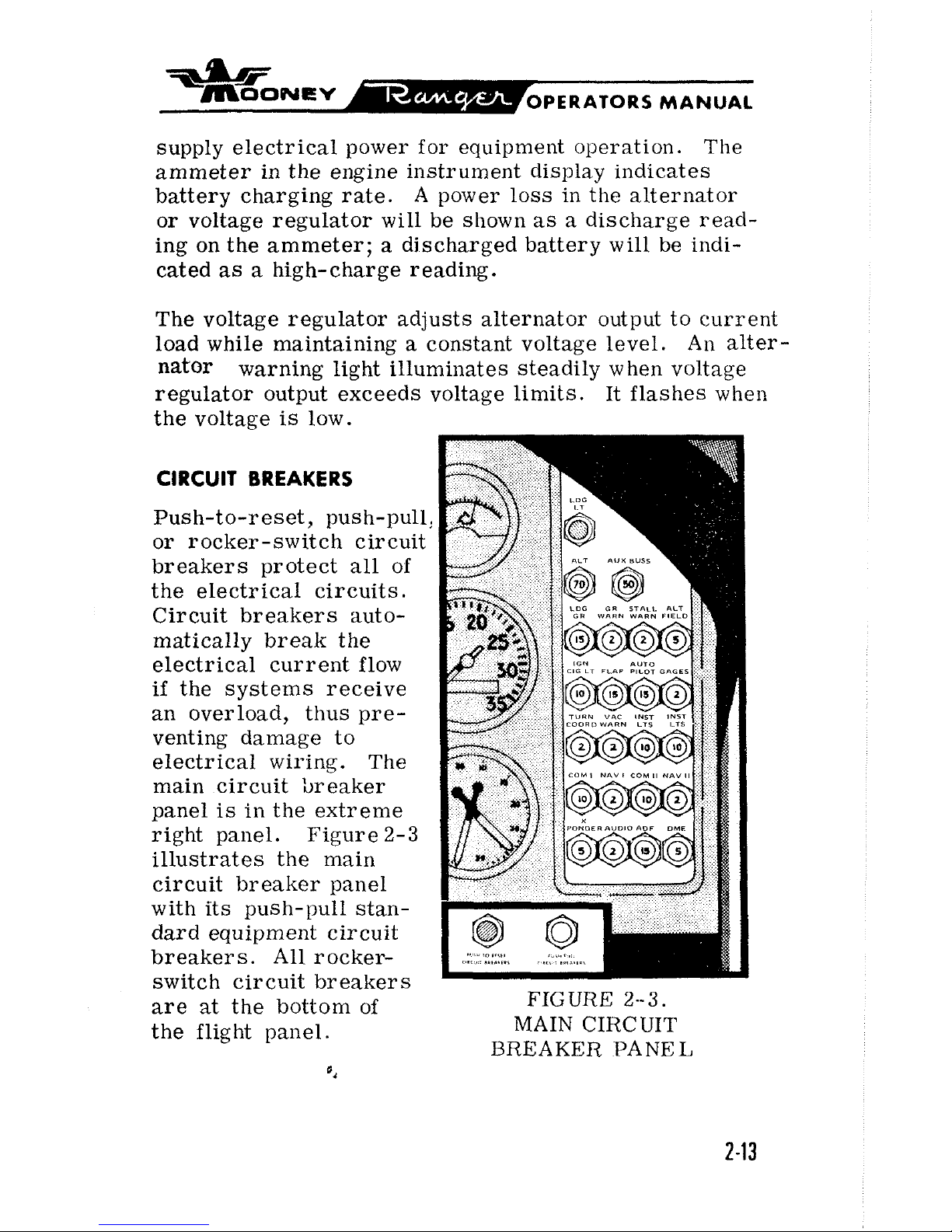
CIRCUIT
BREAKERS
Push-to-reset, push-pull:
or rocker-switch circuit
breakers protect all of
the electrical circuits.
Circuit breakers auto-
matically break the
electrical current flow
if
the systems receive
an overload, thus pre-
venting damage to
electrical wiring. The
main circuit breaker
panel
is
in the extreme
right panel. Figure
2-3
illustrates the main
circuit breaker panel
with its push-pull standard equipment circuit
breakers. All
rocker-
switch circuit breakers
are
at
the bottom of
FIGURE
2--3.
the flight panel. MAIN CIRCUIT
BREAKER
PANEL
ias
~OONEV
OPERATORS MANUAL
*a
LANIIING GEAR
GEAR WARNING
STALI. WARNING
ALTERNATOIT FIELD
IGNITION
&
CIG LTR
A U'I'O1'11.OT (OW"
INSTl{lJh1EN1'S
I'C TITIGGEIT
8.
'TUIIN COOI~rl
VACUUhl WAftNING
INSTRUMENT LTS (LEFT)
INSTRUMENT LTS (RIGlfT)
FUEL
BOOS'I'
PUMP
PITOT HEAT
STRODE 1,IC;HT
ROTATING BLACON (OPT)
RADIO
MASTFII
NAV I (Ol"1
i
COM
11
(01"I'I
NAV 11 101"1'l
'I'I~ANSl'ONI>I~~II lOl>'l'l
AUDIO (OPT)
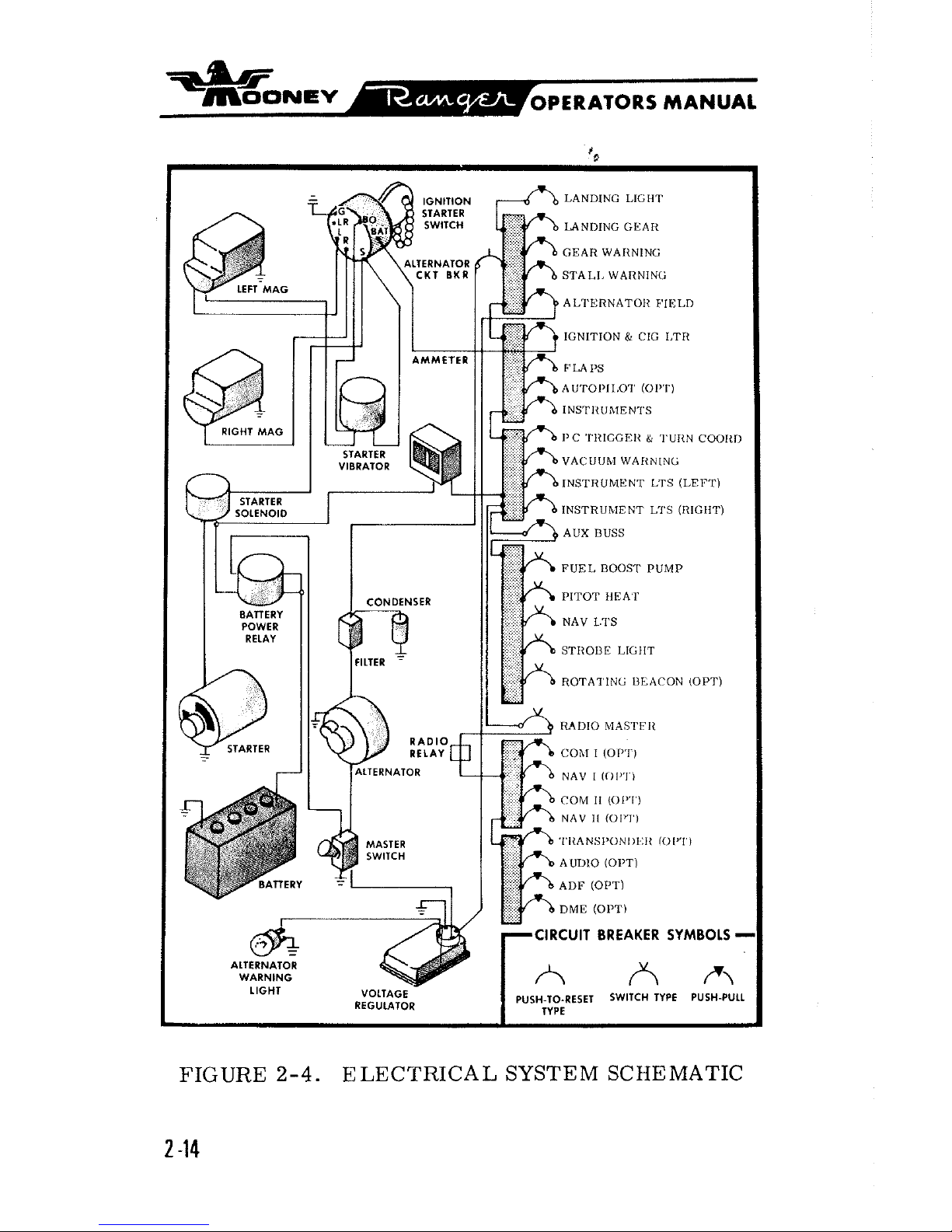
FIGURE
2-4.
ELECTRICAL SYSTEM SCHEMATIC
2 -14
idb
~OONEV-
OPERATORS
MANUAL
The alternator push-pull circuit breaker on the main
breaker panel furnishes an emergency overload break
between the alternator and the individual push-pull
circuit breakers. Resetting the alternator circuit
breaker will usually restore an overloaded circuit. If
pressing the button a second time does not reactivate
the circuit, the alternator circuit breaker must re-
main open and the alternator-field circuit breaker must
be pulled out to break the alternator excitation circuit.
Since the alternator is then cut out of the power circuit,
the storage battery supplies electrical power in steadi-
ly diminishing output with the master switch on.
The alternator-field push-pull circuit breaker furnishes
an emergency break in the alternator field excitation
circuit in the event of alternator or voltage regulator
malfunction. If the regulator output voltage exceeds
limits, the red alternator warning light illuminates
steadily. Turning off all radio equipment, and then
turning master switch off and
on, will reset the voltage
regulator. The alternator annunciator
light should
remain out. If the alternator light comes on again,
pulling out the alternator-field circuit breaker cuts the
alternator out of the power circuit.
Once again the bat-
tery is the only source of electrical power; therefore,
all electrical
equipmerlt not essential for flight should
be turned off and the flight terminated as soon as practical to correct the malfunction.
ANNUNCIATOR LIGHTS
The landing gear lights are at the top of the instrument
panel by the landing gear switch. Annunciator lights
 Loading...