

Page 1

EN - Instructions and warnings for installation and use
IT - Istruzioni ed avvertenze per l’installazione e l’uso
FR - Instructions et avertissements pour l’installation et l’utilisation
ES - Instrucciones y advertencias para la instalación y el uso
Moon
Control unit
MC824H
Page 2
EN
English – 1
ENGLISH
MC824H is an electronic control unit for the automation of swing gates. CAUTION! – Any other use than as specified herein or in environmental condi-
tions other than as stated in this manual is to be considered improper and
is strictly prohibited!
The control unit is ready for connection to external devices by means of the
Bluebus system and for connection to devices belonging to the Opera System
produced by Nice.
The control unit is designed for use of a buffer battery (model PS324, optional
accessory), which ensures that the automation can perform a number of
manoeuvres in the event of a power failure.
Other available accessories are the SMXI, OXI and OX2 receivers.
PRODUCT DESCRIPTION
AND INTENDED USE
1
2.1 - Preliminary checks for installation
Before proceeding with installation, check the condition of the product components, suitability of the selected model and conditions of the intended installation environment:
• Ensure that all material used is in perfect condition and suitable for use.
• Ensure that all conditions of use remain within the limits of product application
(paragraph 2.2).
• Ensure that all parameters of use remain within the limits as stated in the
“Product technical specifications”.
• Ensure that the selected installation environment is compatible with the overall dimensions of the product (fig. 1).
• Ensure that the selected surfaces for product installation are solid and guarantee a stable fixture.
• Ensure that the fixing zone is not subject to flooding. If necessary, mount the
product raised from the ground.
• Ensure that the space around the product enables easy and safe completion
of manual manoeuvres.
• Ensure that all the electric cables used are of the type listed in Tab le 1.
• Ensure that the automation is provided with mechanical stops on both closing and opening.
2.2 - Product application limits
The product may be used exclusively with gearmotors METRO (model ME
3024), MOBY (model MB4024-MB5024), HYPPO (model HY7124) and TOO NA (model TO4024-TO5024-TO7024).
2.3 - Installation
To install the control unit, proceed as shown in fig. 2. To install the other
devices present in the automation, refer to the relevant instruction manuals.
INSTALLATION
2
ELECTRICAL CONNECTIONS
3
CAUTION! – All electrical connections must be made with the unit disconnected from the mains power supply and with the buffer battery disconnected, if present in the automation.
01. Loosen the screws of the cover.
02. Prepare the electrical cable routing holes.
03. Connect the cables as shown in the wiring diagram in fig. 3 and connect
the motors (M1 and M2) to the power supply as shown in fig. 4 and 5.
Note – To facilitate cable connections, the terminals can be removed from
their seats.
3.1 - Initial start-up and electrical connections
CAUTION! – Connections must be made exclusively by qualified personnel.
After powering up the control unit, perform the following checks:
• After a few seconds, make sure that the “Bluebus” LED flashes regularly, with
about one flash per second.
• Make sure that the LEDs on the photocells flash (both on TX and RX). The
type of flashing is not important.
• Make sure that the flashing light connected to the FLASH output is off.
If the above conditions are not satisfied, switch off the power supply to the control unit and check the electrical connections.
3.2 - Description of electrical connections
AERIAL input for the radio receiver aerial
FLASH output for 1 flashing light with 12V maximum 21W bulb
ELS output for 12Vac and maximum 15VA electric lock. It can also be
pro grammed for other functions (see “Level one functions” paragraph)
S.C.A. “Open Gate Light”: output for 1 indication lamp (24V maximum
4W). It can also be programmed for other functions (see “Level one
functions” paragraph)
BLUEBUS input for compatible devices; they are connected in parallel using
two conductors through which both the electricity supply and the
communication signals travel; it is not necessary to observe any
polarity. Each device is individually recognized because a unique
address is assigned to it during installation.
STOP input for devices that cause the immediate interruption of the
manoeuvre in progress (with a short reverse run); NO and NC
contacts, as well as devices with 8.2 kΩ constant resistance
output can be connected to this input.
P. P. input for devices which control Step-by-Step manoeuvres. NO
contacts can be connected to this input.
OPEN input for devices which control only the opening manoeuvres. NO
contacts can be connected to this input.
CLOSE input for devices which control only the closing manoeuvres. NO
contacts can be connected to this input.
ENC1 input encoder - gearmotor 1 (terminal 1, 2); it is not necessary to
observe any polarity
ENC2 input encoder - gearmotor 2 (terminal 4, 5); it is not necessary to
observe any polarity
M1 output for gearmotor 1 (terminal 7, 8, 9)
M2 output for gearmotor 2 (terminal 10, 11, 12).
IMPORTANT! – If the system has a single gearmotor, it must be connected to terminals 10, 11, 12.
3.3 - Connected device address assignment
To enable the control unit to recognise the devices connected to the Bluebus
system, they must be assigned addresses. This operation must be performed
by positioning the electric jumper as described in the instruction manuals of
each individual device.
Connection Cable type Maximum admissible length
A: CONTROL UNIT POWER cable 1 cable 3 x 1,5 mm
2
30 m (note 1)
B: FLASHING LIGHT with aerial cable 1 cable 2 x 0,5 mm
2
20 m
1 shielded cable type RG58 20 m (less than 5 m recommended)
C: BLUEBUS DEVICES cable 1 cable 2 x 0,5 mm
2
20 m (note 2)
D: KEY-OPERATED SELECTOR SWITCH cable 2 cables 2 x 0,5 mm2 (note 3) 50 m
E: GEARMOTOR POWER cable 1 cable 3 x 1,5 mm2 (note 4) 10 m
F: ENCODER CONNECTION cable 1 cable 2 x 1 mm2 (note 4) 10 m
Note 1 – If the power cable is longer than 30 m, a cable with a larger cross-section is required (3 x 2.5 mm
2
) and safety earthing is necessary in the vicinity
of the automation.
Note 2 – If the Bluebus cable is longer than 20 m (up to max. 40 m), a cable with a larger cross-section is required (2 x1 mm
2
).
Note 3 – These 2 cables can be replaced by a single 4 x 0.5 mm
2
cable.
Note 4 – These cables can be replaced by a single 5 x 1.5 mm2cable.
CAUTION! – The cables used must be suited to the installation environment.
TABLE 1 - Technical specifications of electric cables
Page 3
EN
2 – English
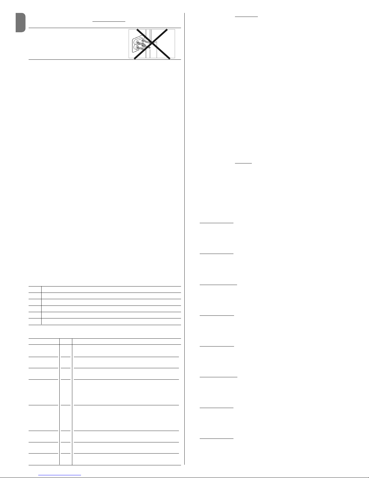
CAUTION! – When assigning addresses to the photocells, the configuration shown in PHOTO 3 below is not permitted.
At the end of the installation procedure or following the removal of photocells or
other devices, the self-learning procedure for these devices described in paragraph 3.4 must be performed.
3.4 - Learning of the connected devices
After the initial power-up, the control unit must be able to recognise the devices
connected to the “Bluebus” and “Stop” inputs. CAUTION! – The learning
procedure must be performed even if no device is connected to the control unit.
The control unit is able to recognise the various connected devices individually
through the learning procedure and detect possible faults with a high degree of
precision. For this reason it is necessary to perform learning every time a new
device is connected or an existing device is removed.
To indicate when the learning procedure is required, LEDs L1 and L2 on the
control unit emit a number of slow flashes:
01. Press and hold down “” and “Set” keys at the same time.
02. Release the keys when LEDs L1 and L2 start flashing quickly (after approx.
3 seconds).
03. Wait a few seconds for the control unit to complete the device learning
phase. At the end of this phase, the “Stop” LED must be lit and LEDs “L1”
and “L2” must be turned off (LEDs L3 and L4 may start flashing).
3.5 - Learning of type of gearmotor connected to the control
unit and the positions of the mechanical stops
After learning the devices (paragraph 3.4), the control unit must learn the connected motor type (see Table 2 ) and the positions of the mechanical stops
(max. Opening and max. Closing positions). In this phase, the travel of each leaf
is measured.
Learning of the mechanical stops can be performed in two ways: automatic or
manual.
Using manual learning it is possible to:
• program the automation with all 8 positions and with the sequence described
in Table 3 .
• customise the automation after performing automatic learning to modify the
position A (fig. 6) of the 2 motors M1 and M2 or to alter the offsets of the leafs
in positions SA and SC (fig. 6).
• check whether faults occur during a manoeuvre for each individual leaf (use
hold-to-run OPEN and CLOSE keys).
Learning procedure in automatic
mode:
01. Press and hold down “Set” and “” keys at the same time.
02. Release the keys when LED L1 begins to flash (installation memorisation
not performed) or when any of the LEDs L1 ... L8 light up (installation
memorisation already performed).
03. Press “” or “” keys within 10 seconds to go to the LED corresponding
to the type of gearmotor connected to the control unit (see Tab le 2 ).
04. Press and hold down the “Set” key for at least 3 seconds to memorize the
se lected gearmotor. After 3 sec. LED L1 starts flashing, then release the
key.
05. Press and hold down “Set” and “” keys at the same time.
06. Release the keys when LEDs L3 and L4 begin to flash quickly (after
approx. 3 seconds).
07. Check that the automation performs the following sequences of manoeuvres:
a - Slow closure of gearmotor M1 as far as mechanical stop
b - Slow closure of gearmotor M2 as far as mechanical stop
c - Slow opening of gearmotor M2 and gearmotor M1 as far as mechani-
cal stop
d - Complete fast closure of gearmotors M1 and M2
Note – If the first two manoeuvres (a and b) are not “closure” but “opening” manoeuvres, press the “open” or “close” keys to stop the learning
procedure. Now, on the gearmotor that performed the opening manoeuvre, invert the polarities of the two wires of the gearmotor (M1: terminals 7
and 9 - M2: terminals 10 and 12) and repeat the procedure from point 01.
08. At the end of the closure manoeuvre of the 2 motors (d), the LEDs L3 and
L4 turn off to indicate that the procedure has been completed correctly.
Learning procedure in manual
mode:
Important – To go from one “position” to a subsequent or previous one, press
and immediately release the “” or “” keys.
01. Press and hold down “Set” and “” keys at the same time.
02. Release the keys when LED L1 begins to flash (installation memorisation
not performed) or when any of the LEDs L1 ... L8 light up (installation
memorisation already performed).
03. Press “” or “” keys within 10 seconds to go to the LED corresponding
to the type of gearmotor connected to the control unit (see Tab le 2 ).
04. Press and hold down the “Set” key for at least 3 seconds to memorize the
se lected gearmotor. After 3 sec. LED L1 starts flashing, then release the key.
05. • position 0 of M1
(LED L1 flashes)
To bring motor 1 to position 0: press and hold down the “” or “”
keys. On reaching the position, release the key to stop the manoeuvre.
To memorise the position, press and hold down the “Set” key for at least
3 seconds and then release it (after 2 seconds LED L1 remains on and
on releasing the “Set” key LED L2 begins flashing).
• position 0 of M2
(LED L2 flashes)
To bring motor 2 to position 0: press and hold down the “” or “”
keys. On reaching the position, release the key to stop the manoeuvre.
To memorise the position, press and hold down the “Set” key for at least
3 seconds and then release it (after 2 seconds LED L2 remains on and
on releasing the “Set” key LED L3 begins flashing).
• position SA of M2
(LED L3 flashes)
To bring motor 2 to position SA: press and hold down the “” or “”
keys. On reaching the position, release the key to stop the manoeuvre.
To memorise the position, press and hold down the “Set” key for at least
3 seconds and then release it (after 2 seconds LED L3 remains on and
on releasing the “Set” key LED L4 begins flashing).
• position A of M1
(LED L4 flashes)
To bring motor 1 to position A: press and hold down the “” or “”
keys. On reaching the position, release the key to stop the manoeuvre.
To memorise the position, press and hold down the “Set” key for at least
3 seconds and then release it (after 2 seconds LED L4 remains on and
on releasing the “Set” key LED L5 begins flashing).
• position A of M2
(LED L5 flashes)
To bring motor 2 to position A: press and hold down the “” or “”
keys. On reaching the position, release the key to stop the manoeuvre.
To memorise the position, press and hold down the “Set” key for at least
3 seconds and then release it (after 2 seconds LED L5 remains on and
on releasing the “Set” key LED L6 begins flashing).
• position SC of M1
(LED L6 flashes)
To bring motor 1 to position SC: press and hold down the “” or “”
keys. On reaching the position, release the key to stop the manoeuvre.
To memorise the position, press and hold down the “Set” key for at least
3 seconds and then release it (after 2 seconds LED L6 remains on and
on releasing the “Set” key LED L7 begins flashing).
• position 1 of M1
(LED L7 flashes)
To bring motor 1 to position 1: press and hold down the “” or “”
keys. On reaching the position, release the key to stop the manoeuvre.
To memorise the position, press and hold down the “Set” key for at least
3 seconds and then release it (after 2 seconds LED L7 remains on and
on releasing the “Set” key LED L8 begins flashing).
• position 1 of M2
(LED L8 flashes)
To bring motor 2 to position 1: press and hold down the “” or “”
keys. On reaching the position, release the key to stop the manoeuvre.
To memorise the position, press and hold down the “Set” key for at least
3 seconds and then release it to exit programming (after 2 seconds LED
L8 remains on until the “Set” key is released).
PHOTO 3
NON-PERMITTED CONFIGURATION
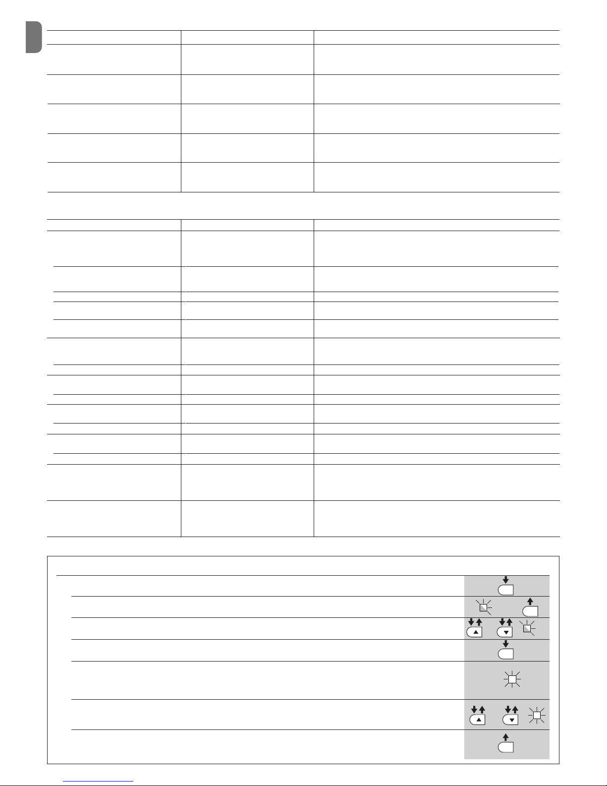
TABLE 3 (fig. 6)
Position LED Description
Position 0
(motor 1)
Position 0
(motor 2)
Position SA
(motor 2)
Position A
(motor 1)
Position A
(motor 2)
Position SC
(motor 1)
Position 1
(motor 1)
Position 1
(motor 2)
Maximum closing position: when leaf 1 reaches closing
mechanical stop
Maximum closing position: when leaf 2 reaches closing
mechanical stop
Opening offset: when leaf 2 passes this position the opening of leaf 1 begins
Desired opening position: position at which the leaf connected to motor 1 must stop at the end of an opening
manoeuvre. This position does not need to coincide with
the opening mechanical stop but can be chosen as desired between the positions 0 and 1
Desired opening position: position at which the leaf connected to motor 2 must stop at the end of an opening
manoeuvre. This position does not need to coincide with
the opening mechanical stop but can be chosen as desired between the positions 0 and 1
Closing offset: when leaf 1 reaches this position, leaf 2
begins to close
Maximum opening position: when leaf 1 reaches the opening mechanical stop
Maximum opening position: when leaf 2 reaches the opening mechanical stop
L1
L2
L3
L4
L5
L6
L7
L8
TABLE 2
Led Gearmotor type
L1 MB4024 - MB5024 - HY7024
L2 ME3024
L3 TO4024
L4 TO5024
L5 TO7024
Page 4

EN
English – 3
The control unit has 3 keys OPEN (), STOP (SET), CLOSE () that can be
used both for controlling the unit during testing and for programming the available functions.
The programmable functions available are divided into 2 levels and their relative
operating status is displayed by means of the 8 LEDs (L1…L8) on the control
unit (LED lit = function active; LED off = function not active).
Use the programming keys:
OPEN (): – key for controlling gate opening; – selection key during pro-
gramming.
STOP/SET: key for stopping a manoeuvre; if pressed for more than 5 seconds,
it enables entry to programming mode.
CLOSE (): – key for controlling gate closure; – selection key during pro-
gramming.
5.1 - Level one programming (ON-OFF functions)
All level 1 functions are set by default to “OFF” and may be modified at any
time. To check the functions see Table 5 . For the programming procedure see
Table 6 .
Note – These procedures can be performed again at any time, even after a
new device has been connected to the control unit.
IMPORTANT – In the programming procedure, the maximum time interval that
can elapse between activation of one key and the next is 10 seconds. When
this time elapses, the procedure terminates automatically, memorising the
modifications made up until then.
These are the most important phases of automation set-up for ensuring maximum system safety. The test can also be performed as a periodic check of
automation devices. Testing and commissioning of the automation must be
performed by skilled and qualified personnel, who are responsible for the tests
required to verify the solutions adopted according to the risks present, and for
ensuring observance of all legal provisions, standards and regulations, and in
particular all requirements of the standard EN 12445, which establishes the test
methods for checking automations for doors and gates.
The additional or optional devices must undergo a specific test for functionality
and correct interaction with MC824H. Refer to the instruction manuals of the
individual devices.
4.1 - Testing
The sequence of operations to be performed for testing refers to a typical system:
1 Release the gearmotors manually as described in the relevant instruction
manual and check that it is possible to move the leafs manually both in
opening and closing. The gearmotor force required to perform these movements must not be greater than 390 N.
2 Lock the gear motors (see respective instruction manual).
3 Using the control devices (transmitter, key-operated selector switch or con-
trol pushbuttons), perform tests of opening, closing and stopping the gate,
and ensure that leaf movement corresponds to specifications. Test several
times to check for leaf movement and any defects in assembly or adjustment and any possible points of friction.
4 Check operation of all system safety devices one at a time (photocells, sen-
si tive edges, etc.). Each time a device is activated the “BLUEBUS” LED on
the control unit must flash rapidly twice to confirm acknowledgement of the
event.
5 If hazardous situations generated by the moving leafs are protected by
means of impact force limitation, measure the force as specified in the standard EN 12445. If gearmotor force control is used as auxiliary function with
the system for reduction of impact force, test and identify the setting that
obtains the best results.
4.2 - Commissioning
Commissioning can only be performed after positive results of all test
phases.
1 Prepare the automation technical documentation, which must contain the
following documents: overall drawing of the automation, electrical wiring
diagram, risk assessment and relative solutions adopted (refer to the relevant forms on our website www.niceforyou.com), manufacturer’s declaration of conformity for all devices used and installer’s declaration of conformity.
2 Affix a dataplate on the door, specifying at least the following data: type of
automation, name and address of manufacturer (responsible for commissioning), serial number, year of construction and CE mark.
3 Before commissioning the automation, ensure that the owner is adequately
informed of all associated risks and hazards.
Manual learning of all the positions can be performed at any time, even after
performing installation. The procedure must commence from point 01.
To alter the “position A” of motors 1 and 2 or the “offsets SA and SC”, begin the
procedure from point 01 and at point 04 start directly from the desired position,
avoiding the previous positions.
3.6 - Checking movement of gate leafs
At the end of the learning procedure for the type of gearmotor and the positions
of the mechanical stops, it is advisable to make the control unit perform a few
opening and closing manoeuvres to ensure that the gate moves correctly and
to check for installation or setting defects or other faults.
01. Press the “Open” key and check that the opening manoeuvre includes the
acceleration, constant speed and deceleration phases and that the leafs
stop a few centimetres from the opening mechanical stops.
02. Press the “Close” key and check that the closure manoeuvre includes the
acceleration, constant speed and deceleration phases and that the leafs
stop a few centimetres from the closure mechanical stops.
03. Make sure that the flashing light flashes at regular intervals (0.5 sec on, 0.5
sec off) during manoeuvres.
TESTING AND COMMISSIONING
4
TABLE 5 - Level one functions
Led Function Description
Function ACTIVE: an automatic gate closure manoeuvre is
performed after the programmed pause time. Factory setting of Pause time: 30 seconds. Function NOT ACTIVE
:
function is “semiautomatic” type.
Function ACTIVE: if the photocells are activated during the
opening or closing manoeuvre, the pause time is reduced
to 5 seconds regardless of the programmed pause time.
With “automatic closure” disabled, if the photocells are
activated during closure the “automatic closure” is activated with the programmed “pause time”.
Function ACTIVE: in the event of a power failure, even of
short duration, when power is restored the control unit de tects gate open and automatically starts a closure ma noeuvre, preceded by 5 seconds of pre-flashing.
Function NOT ACTIVE
: when power is restored the gate
remains stopped.
F
unction ACTIVE: 1 minute after the end of the manoeuvre, the control unit turns off the “Bluebus” output (connected devices) and all the LEDs apart from the Bluebus
LED which will flash more slowly. When the control unit
receives a command normal operation is restored. This
function reduces consumption.
Function ACTIVE: the “electric lock” output switches its
operation to “courtesy light”.
F
unction ACTIVE: a 3 second pause can be added be tween the flashing light signal and the start of the manoeuvre to provide advance warning of a hazard situation.
Function NOT ACTIVE
: flashing light signal coincides with
the start of the manoeuvre.
F
unction ACTIVE: all the commands corresponding to
“Close” (“Close” input or “Close” radio control) are re pla ced by the “Partial open 1” command.
F
unction ACTIVE: the “gate open light” output on the control unit switches to the “maintenance light” function.
PROGRAMMING
5
L1 Automatic
closure
L2 Reclose
after photo
L3 Always close
L4 Stand by
L5 Electric lock
Courtesy light
L6 Pre-flash
L7 “Close” becomes
“Partial open 1”
L8 Gate open light
or Maintenance
light
Page 5
EN
4 – English
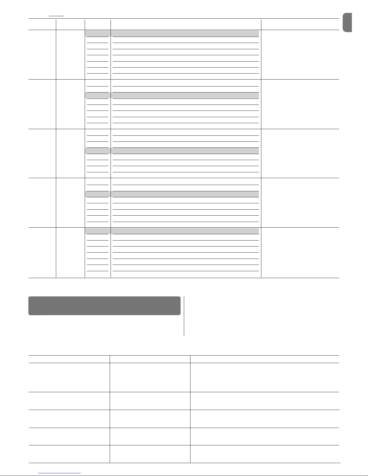
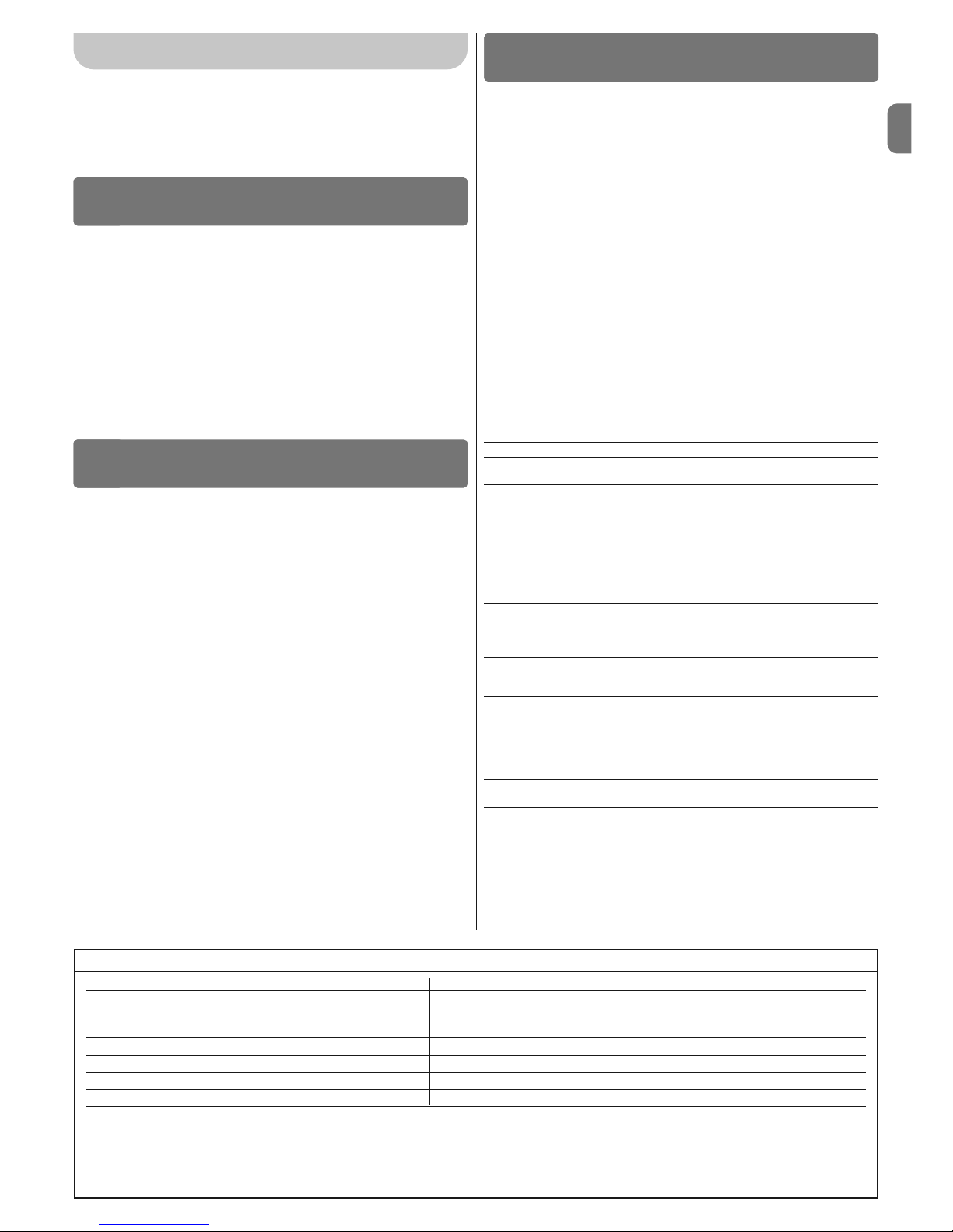
TABLE 7 - Programming procedure (level two functions)
01. Press and hold down the key “Set” (for approx. 3 seconds);
02. Release the key when LED L1 starts flashing;
03. Press keys ” or “” to move from the flashing LED to the LED associated with the “input LED”;
04. Press and hold the “Set” key through to completion of point 06;
05. Wait approx. 3 seconds, until illumination of the LED representing the current level of the parameter to be modified;
06. Press keys “” or “” to move the LED representing the value of the parameter;
07. Release the “Set” key;
08. Wait 10 seconds (maximum time) to exit the programming mode.
Note – During this procedure, points 03 to 07 need to be repeated when programming other parameters during the phase itself.
SET
SET
SET
SET
L1
o
o
3 s
10 s
TABLE 8 - Functions (second level)
Input Parameter Led Value Description
LED (level)
L1
L1
L2
L3
L4
L5
L6
L7
L8
5 seconds
15 seconds
30 seconds
45 seconds
60 seconds
80 seconds
120 seconds
180 seconds
Sets the pause time, namely the time
which lapses before automatic closure.
This will only take effect if closing is
active.
Pause time
L2 L1
L2
L3
L4
L5
L6
L7
L8
Open – Stop – Close – Stop
Open – Stop – Close - Open
Open – Close – Open- Close
Apartment block
Apartment block 2 (more than 2” generates stop)
Step-by-step 2 (less than 2” generates partial open)
Hold-to-run
Opening in semi-automatic mode, closing in hold-to-run mode
Sets the sequence of controls associated with the Step-by-Step input or
the radio control.
Step by
step function
L3 L1
L2
L3
L4
L5
L6
L7
L8
Very slow
Slow
Medium
Fast
Very fast
Extremely fast
Fast opening, Slow Closing
Extremely fast Opening, Medium Closing
Sets the motor speed during normal
travel.
Motor
speed
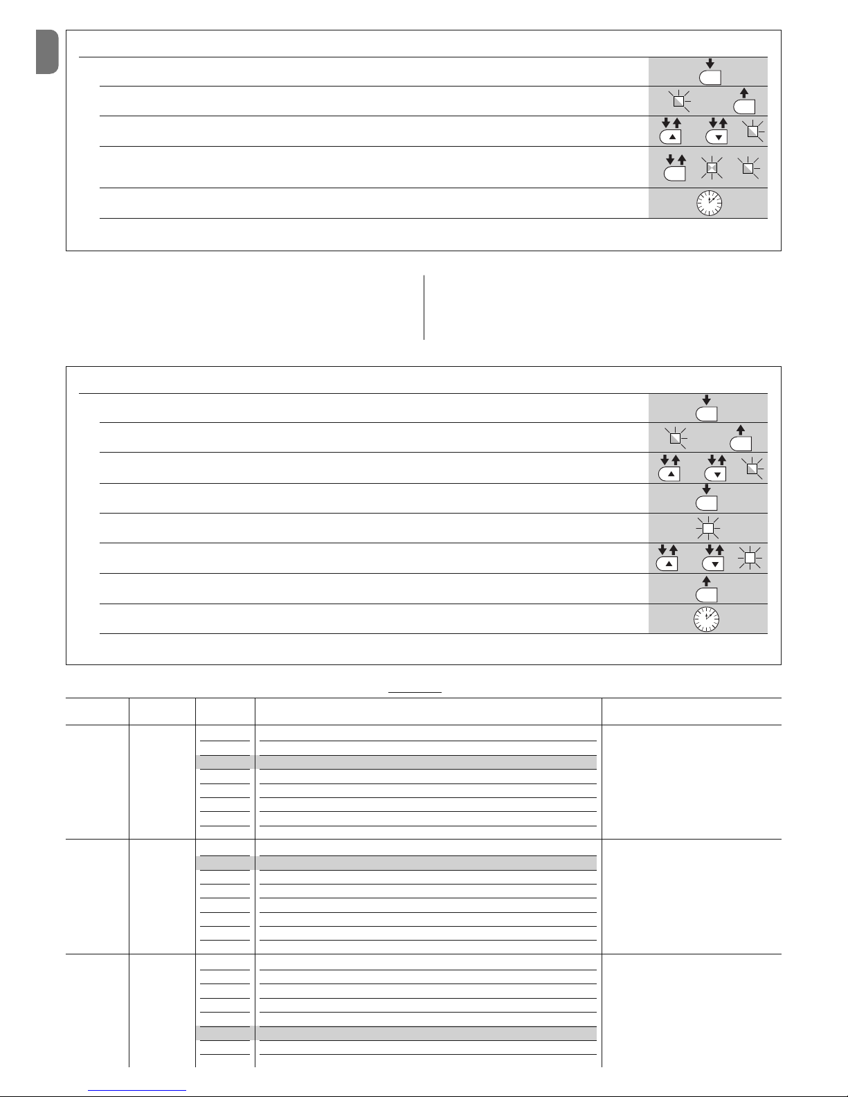
TABLE 6 - Programming procedure (level one functions)
01. Press and hold down the key “Set” (for approx. 3 seconds).
02. Release the key when L1 LED starts flashing;
03. Press keys “” or “” to move from the flashing LED to the LED associated with the function to be modified;
04. Press “Set” to change the status of the function:
(short flash = OFF; long flash = ON)
05. Wait 10 seconds (maximum time) to exit the programming mode.
Note – During this procedure, points 03 and 04 need to be repeated when programming other functions to “ON” or “OFF” during the phase itself.
SET
SET
SET
L1
o
3 s
10 s
5.2 - Level two programming (adjustable parameters)
All level 2 functions are set by default as highlighted in grey in Table 8, and may
be modified at any time as explained in Table 7.
The parameters can be set on a scale from 1 to 8. To check the value corresponding to each LED see Table 8.
IMPORTANT – In the programming procedure, the maximum time interval that
can elapse between activation of one key and the next is 10 seconds. When
this time elapses, the procedure terminates automatically, memorising the
modifications made up until then.
Page 6
EN
English – 5
Note – Grey colour represents the factory setting.
TABLE 8 - Functions (second level)
Imput Parameter Led Value Description
LED (level)
L7
L1
L2
L3
L4
L5
L6
L7
L8
500
1000
1500
2500
5000
10000
15000
20000
Sets the control unit maintenance request: indicates by way of “maintenance” warning light that the ma xi mum
number of manoeuvres has been exceeded.
Maintenance warning
L8 L1
L2
L3
L4
L5
L6
L7
L8
Manoeuvre 1 result (most recent)
Manoeuvre 2 result
Manoeuvre 3 result
Manoeuvre 4 result
Manoeuvre 5 result
Manoeuvre 6 result
Manoeuvre 7 result
Manoeuvre 8 result
The type of fault that has occurred in
the last 8 manoeuvres can be established.
List of
faults
L4 L1
L2
L3
L4
L5
L6
L7
L8
0 - No discharge
Level 1 - Minimum discharge
Level 7 - Maximum discharge
Sets duration of “short inversion” of
both motors after performing Close
manoeuvre.
Motor
discharge
after closing
L5 L1
L2
L3
L4
L5
L6
L7
L8
Level 1 - Minimum Force
Level 8 - Maximum Force
Sets force of both motors, with 8 levels available.
Motor force
L6 L1
L2
L3
L4
L5
L6
L7
L8
Pedestrian 1 (Opening of leaf 2 to approx. 1/4 of total opening)
Pedestrian 1 (Opening of leaf 2 to approx. 1/4 of total opening)
Pedestrian 3 (Opening of leaf 2 to approx. 3/4 of total opening)
Pedestrian 4 (Complete opening of leaf 2)
Partial 1 (Opening of two leafs to 1/4 of total opening)
Partial 1 (Opening of two leafs to 1/2 of total opening)
Partial 3 (Opening of two leafs to 3/4 of total opening)
Partial 4 (Complete opening of the two leafs)
Sets type of opening associated with
“Partial open 1” command.
Pedestrian
or partial
open
TABLE 9 - Flashing light signals (FLASH)
Signal Cause Solution
1 short flash
1 second pause
1 short flash
Bluebus system error At the start of the manoeuvre, the devices connected to Bluebus do not
correspond to those recognized during the self-learning phase. One or
more devices may be faulty; check and, if necessary, replace them. In
case of modifications repeat the device self-learning process (see paragraph 3.4).
2 short flashes
1 second pause
2 short flashes
Photocell activated At the start of the manoeuvre, one or more photocells do not enable
movement; check to see if there are any obstructions.
3 short flashes
1 second pause
3 short flashes
“Obstacle detection” function
activation
During the movement, the motors experienced excessive friction; identify
the cause.
4 short flashes
1 second pause
4 short flashes
STOP input activation At the start of the manoeuvre or during the movement, the STOP input
was activated; identify the cause.
5 short flashes
1 second pause
5 short flashes
Error on internal parameters in control
unit
Wait at least 30 seconds, then try giving a command. if the condition persists it means there is a malfunction and the electronic board must be
replaced.
Some devices are able to emit signals that serve to recognise their state of
operation or possible faults.
If a flashing light is connected to the FLASH output on the control unit, it will
flash at intervals of 1 second during a manoeuvre. If faults occur, the flashing
light will emit a sequence of two shorter flashes separated by a 1 second
pause. Table 9 shows the cause and solution for each type of signal.
The LEDs on the control unit also emit signals. Table 10 shows the cause and
solution for each type of signal.
It is possible to verify faults that have occurred during the last 8 manoeuvres.
See Table 11.
WHAT TO DO IF...
(troubleshooting guide)
6
Page 7
EN
6 – English
TABLE 9 - Flashing light signals (FLASH)
Flashes Problem Solution
6 short flashes
1 second pause
6 short flashes
Maximum limit of manoeuvres per
hour exceeded
Wait a few minutes until the manoeuvre limiting device falls to below the
maximum limit.
7 short flashes
1 second pause
7 short flashes
Electric circuits fault Wait at least 30 seconds, then try giving a command. If the condition per-
sists it means there is a serious malfunction and the electronic board must
be replaced.
8 short flashes
1 second pause
8 short flashes
A command is already present that di sables execution of other commands
Check the type of command that is always present; for example, it could be
a command from a timer on the “open” input.
9 short flashes
1 second pause
9 short flashes
The manoeuvre does not begin be ca u se it has been blocked by the transmission of an automation block command
Release the automation by giving the “Automation release” command.
10 short flashes
1 second pause
10 short flashes
“Obstacle detection” by encoder function activated
During the movement, the motors experienced excessive friction; identify
the cause.
TABLE 10 - Signals given by LEDs on control unit
Led Problem Solution
BLUEBUS
Off
On
1 flash per second
2 quick flashes
Series of flashes separated by one
second pause
Fault
Serious fault
Everything normal
Input status variation
Various
Check that the control unit is powered. Check that the fuses have not
blown: if they have, check the cause of the fault and replace with others
with the same value
A serious fault has occurred: try disconnecting electrical power from the
control unit. If the problem persists it will be necessary to replace the electronic board
Control unit works correctly
Normal if one of the inputs (PP, STOP, OPEN, CLOSE) changes: photocells
activated or a transmitter is used
Refer to Table 9
STOP
Off
On
Activation of the devices connected to
the STOP input
Everything normal
Check the devices connected to the STOP input
STOP input active
P. P.
Off
On
Everything normal
S.S. input activation
S.S. input not active
Normal if the device connected to the S.S. input is active
OPEN
Off
On
Everything normal
OPEN input activation
OPEN input not active
Normal if the device connected to the OPEN input is active
CLOSE
Off
On
Everything normal
CLOSE input activation
CLOSE input not active
Normal if the device connected to the CLOSE input is active
L1 - L2
Slow flashing Change in number of devices
connected to Bluebus or device selflearning not performed
The device self-learning process must be performed (see paragraph 3.4)
L3 - L4
Slow flashing Change in self-learning of the motor
types or the positions of the mechanical stops
The self-learning process must be performed (see paragraph 3.5)
TABLE 11 - Fault log
01. Press and hold down the “Set” key for approx. 3 seconds;
02. Release the key when LED L1 starts flashing;
03. Press keys “” or “” to move from the flashing LED to L8 LED (“input LED”) for the “Fault log” parameter;
04. Press and hold the “Set” key through to completion of point 06;
05. Wait approx. 3 seconds until the LEDs representing the levels corresponding o the manoeuvres with faults illuminate.
The LED L1 indicates the result of the most recent manoeuvre while L8 indicates the eighth-to-last manoeuvre. If the LED
is on this means that a fault has occurred; if the LED is off, everything is normal;
06. Press keys “” and “” to select the required manoeuvre: the corresponding LED performs a number of flashes equal to
those normally performed by the flashing light;
07. Release the “Set” key.
SET
SET
SET
SET
L1
o
e
3 s
3 s
L8
Page 8
EN
English – 7
The following optional accessories are available for the control unit MC824H:
SMXI, OXI, OX2 family receivers and Oview programming unit.
7.1 - Connecting a radio receiver
The control unit has a connector for connecting radio receivers (optional accessories) belonging to the SMXI, OXI and OX2 families. To connect a receiver, disconnect power from the control unit and proceed as shown in fig. 7. Table 12
and Table 13 show the commands corresponding to the outputs on the control
unit.
7.2 - Connecting Oview programming unit
Connector BusT4.8 on the control unit enables connection of the programming
unit Oview which enables complete and rapid management of installation,
maintenance and troubleshooting of any malfunctions of the whole automation
system. To gain access to the connector, proceed as shown in fig. 8 and connect the connector to its seat. Oview can be placed at a distance from the control unit, with up to 100 m of cable. It can be connected simultaneously to up to
16 control units and can remain connected to the control unit also during normal operation of the automation. In this case a specific “user” menu enables
direct delivery of commands to the control unit.
It is also possible to update the firmware.
If a OXI type radio receiver is present in the control unit, Oview enables access
to the parameters of the transmitters memorised in this receiver.
Further information is available in the relative instruction manual.
7.3 - Connecting model PS324 buffer battery
To connect the buffer battery, see fig. 9. For other information, refer to the relevant instruction manual.
ADDITIONAL INFORMATION: Accessories
7
TABLE 12 - SMXI / SMXIS
output command
“P.P.” (Step-by-Step) command
“Partial open 1” command
“Opening” command
“Closing” command
Output No. 1
Output No. 2
Output No. 3
Output No. 4
TABLE 13 - OXI /OX2
No Command Description
Command according to Step-by-Step logic
Partial open (Complete opening of leaf 2)
Performs Open only
Performs Close only
Stops manoeuvre
Apartment block control
Gives command even when automation is blocked or
commands are in progress
Partial open (Opening of leaf 2 to ½ of normal opening)
Partial open (Opening of 2 leafs to ½ of normal opening)
Opens and then blocks the automation
Closes and then blocks the automation
Blocks the automation in current position
Release automation; operation resumes from point at
which it had stopped
Courtesy light comes on with timed turning off
The CL turns on and off in step-by-step mode
1 Step by step
2 Partial open 1
3 Open
4 Close
5 Stop
6 Step by step +
Apartment block
7 Step by step
Hi priority
8 Partial open 2
9 Partial open 3
10 Open+block
automation
11 Close+block
automation
12 Block automation
13 Release
automation
14 Courtesy light
timer on
15 Courtesy light on-off
DISPOSAL OF THE PRODUCT
This product is an integral part of the automation, and therefore, they
must be disposed of together.
As for the installation operations, at the end of the life of this product, the dismantling operations must be performed by qualified personnel.
This product is made from different types of materials: some can be recycled,
others must be disposed of. Please inform yourselves on the recycling or disposal systems provided for by the laws in force in your area, for this category of
product.
CAUTION! – some parts of the product can contain polluting or dangerous
substances which, if dispersed in the environment, may cause serious harm to
the environment and human health.
As indicated by the symbol at the side, it is forbidden to
throw this product into domestic refuse. Therefore, follow the
“separated collection” instructions for disposal, according to
the methods provided for by local regulations in force, or
redeliver the product to the retailer at the moment of purchase of a new, equivalent product.
CAUTION! – the regulations in force at local level may envisage heavy sanctions in case of abusive disposal of this product.
Page 9

EN
8 – English
WARNINGS: • All technical characteristics stated refer to an ambient temperature of 20°C (±5°C). • Nice S.p.a reserves the right to modify the product at any time
while maintaining the same functionalities and intended use.
Power supply 230 Vac (+10% -15%) 50/60 Hz
Nominal power absorbed from mains 200 W
Power absorbed from mains 2 W
“standby - All” operation
(including receiver)
Power absorbed from control panel less than 100 mW
24 Vdc side with “standby - All”
operation (including receiver)
Flashing light output 1 “LUCYB” type flashing light (12 V, 21 W lamp)
Courtesy light output 1 max. 24 V max. 4 W lamp (output voltage may vary between -30% and +50%, output may also control small relays)
Electric lock output 1 max. 12 Vac max. 15 VA electric lock
Gate open light output one 24 V max. 4 W lamp (output voltage may vary between -30% and +50%, output may also control small relays)
Maintenance light output one 24 V max. 4W lamp (output voltage may vary between -30% and +50%, output may also control small relays)
BLUEBUS output 1 output with maximum load 15 Bluebus units (maximum 6 pairs of MOFB or MOFOB photocells + 2 pairs of MOFB or
MOFOB photocells assigned as Opening devices + max. 4 MOMB or MOTB control devices
STOP Input For normally closed, normally open or 8.2 kΩ constant resistance contacts in self-learning mode (a change from the
memorised state prompts the “STOP” command)
PP input for normally open contacts (closure of the contact prompts the P.P. command)
OPEN input for normally open contacts (closure of the contact prompts the OPEN command)
CLOSE input for normally open contacts (closure of the contact prompts the CLOSE command)
Radio connector SM connector for SMXI, OXI and OX2 family receivers
Radio AERIAL input 52 Ω for RG58 or similar type cable
Programmable functions 8 ON-OFF type functions and 8 adjustable functions
Functions in self-learning mode • Self-learning of devices connected to the BlueBus output
• Self-learning of type of device connected to “STOP” terminal (NO, NC or 8.2 kΩ resistance contact)
• Self-learning of leaf travel and automatic calculation of deceleration and partial opening points (vary according to
installation)
Operating temperature - 20 °C ÷ 50 °C
Use in particularly acid, saline or NO
potentially explosive atmospheres
Protection rating IP 54
Dimensions (mm) 310 x 232 x H 122
Weight (kg) 4,1
TECHNICAL CHARACTERISTICS OF THE PRODUCT
Page 10
IT
Italiano – 1
ITALIANO
MC824H è una centrale elettronica per l’automatizzazione di cancelli ad ante
battenti. AT TENZIONE! – Qualsiasi altro uso diverso da quello descritto e
in condizioni am bientali diverse da quelle riportate in questo manuale è
da considerarsi improprio e vietato!
La Centrale di comando è predisposta per essere collegata a dispositivi esterni
tramite il sistema Bluebus ed anche per il collegamento a dispositivi appartenenti al Sistema Opera di Nice.
La Centrale è predisposta per ospitare una batteria tampone (mod. PS324,
accessorio opzionale) che nel caso di mancanza dell’energia elettrica (blackout elettrico) garantisce all’automatismo di eseguire alcune manovre.
Altri accessori disponibili, sono i ricevitori della famiglia SMXI, OXI e OX2.
DESCRIZIONE DEL PRODOTTO
E DESTINAZIONE D’USO
1
2.1 - Verifiche preliminari all’installazione
Prima di procedere all’installazione, è necessario verificare l’integrità dei componenti del prodotto, l’adeguatezza del modello scelto e l’idoneità dell’ambiente destinato all’installazione:
• Verificare che tutto il materiale da utilizzare sia in ottimo stato e adatto all’uso
previsto.
• Verificare che tutte le condizioni di utilizzo rientrino nei limiti d’impiego del prodotto (paragrafo 2.2).
• Verificare che tutti parametri di utilizzo rientrino nei limiti dei valori riportati nelle “Caratteristiche tecniche del prodotto”.
• Verificare che l’ambiente scelto per l’installazione sia compatibile con l’ingombro totale del prodotto (fig. 1).
• Verificare che la superficie scelta per l’installazione del prodotto sia solida e
possa garantire un fissaggio stabile.
• Verificare che la zona di fissaggio non sia soggetta ad allagamenti; prevedere
il montaggio del prodotto adeguatamente sollevato da terra.
• Verificare che lo spazio intorno al prodotto consenta una facile e sicura esecuzione delle manovre manuali.
• Verificare che tutti i cavi elettrici da utilizzare siano del tipo elencato nella
Tabella 1.
• Verificare che nell’automazione siano presenti gli arresti meccanici sia in Chiusura sia in Apertura.
2.2 - Limiti d’impiego del prodotto
Il prodotto può essere utilizzato esclusivamente con i motoriduttori METRO
(mod. ME3024), MOBY (mod. MB4024-MB5024), HYPPO (mod. HY7124) e
TOONA (mod. TO4024-TO5024-TO7024).
2.3 - Installazione
Per il fissaggio della Centrale, procedere come mostrato in fig. 2. Per eseguire
l’installazione degli altri dispositivi presenti nell’automazione, fare riferimento ai
rispettivi manuali d’istruzioni.
INSTALLAZIONE
2
COLLEGAMENTI ELETTRICI
3
ATTENZIONE! – Tutti i collegamenti elettrici devono essere eseguiti in
assenza di alimentazione elettrica di rete e con la batteria tampone scollegata, se presente nell’automazione.
01. Svitare le viti del coperchio;
02. Predisporre i fori per il passaggio dei cavi elettrici;
03. Eseguire i collegamenti dei cavi facendo riferimento allo schema elettrico di
fig. 3 e per il collegamento dell’alimentazione elettrica e dei motori (M1 e
M2) fare riferimento alle fig. 4 e 5. Nota – Per facilitare i collegamenti dei
cavi, è possibile estrarre i morsetti dalle proprie sedi.
3.1 - Prima accensione e verifica dei collegamenti
ATTENZIONE! – Le operazioni di collegamento devono es sere eseguite
esclusivamente da personale qualificato.
Dopo aver dato alimentazione elettrica alla Centrale di comando, eseguire le
seguenti verifiche:
• Passati alcuni secondi, verificare che il Led “Bluebus” lampeggi regolarmente
con frequenza di 1 lampeggio al secondo;
• Verificare che i Led delle fotocellule, sia TX sia RX, emettano lampeggi. Il tipo
di lampeggio emesso non è significativo;
• Verificare che il lampeggiante collegato all’uscita FLASH sia spento.
Se questo non avviene è necessario togliere l’alimentazione elettrica alla Centrale e controllare i vari collegamenti elettrici effettuati.
3.2 - Descrizione dei collegamenti elettrici
ANTENNA ingresso per l’antenna di un ricevitore radio
FLASH uscita per 1 lampeggiante con lampada da 12 V e massimo 21 W
ELS uscita per elettroserratura da 12 Vac e massimo 15 VA. Può essere
programmata con altre funzioni (vedere “Funzioni 1° livello”)
S.C.A. “Spia Cancello Aperto”: uscita per 1 lampada di segnalazione da
24 V e massimo 4 W. Può essere programmata con altre funzioni
(vedere “Funzioni 1° livello”)
BLUEBUS ingresso per dispositivi compatibili; collegamento dei dispositivi in
parallelo tramite 2 conduttori nel quale transita sia l’alimentazione
elettrica sia i segnali di comunicazione; nessuna polarità da
rispettare. Ogni dispositivo viene riconosciuto singolarmente dalla
Centrale grazie ad un numero univoco (indirizzo) che viene
assegnato durante l’installazione
STOP ingresso per dispositivi che con il loro intervento provocano
l’arresto immediato della manovra in atto, seguito da una breve
inversione; possibilità di collegare contatti di tipo NA, NC oppure
dispositivi con uscita a resistenza costante 8,2 kΩ
P. P. ingresso per dispositivi che con il loro intervento provocano la
manovra con modalità Passo Passo; possibilità di collegare contatti
di tipo NA
OPEN ingresso per dispositivi che con il loro intervento provocano solo la
manovra di Apertura; possibilità di collegare contatti di tipo NA
CLOSE ingresso per dispositivi che con il loro intervento provocano solo la
manovra di Chiusura possibilità di collegare contatti di tipo NA
ENC1 ingresso encoder - motoriduttore 1 (morsetto 1, 2); nessuna
polarità da rispettare
ENC2 ingresso encoder - motoriduttore 2 (morsetto 4, 5); nessuna
polarità da rispettare
M1 uscita per motoriduttore 1 (morsetto 7, 8, 9)
M2 uscita per motoriduttore 2 (morsetto 10, 11, 12).
IMPORTANTE! – Se nell’impianto è presente un solo motoriduttore, questo deve essere collegato ai morsetti 10, 11, 12.
3.3 - Indirizzamento dei dispositivi collegati
Per permettere alla Centrale di riconoscere i dispositivi collegati al sistema
Bluebus, è necessario eseguire l’indirizzamento di quest’ultimi. Questa opera-
Collegamento Tipo di cavo Lunghezza massima consentita
A: Cavo ALIMENTAZIONE CENTRALE DI COMANDO 1 cavo 3 x 1,5 mm
2
30 m (nota 1)
B: Cavo LAMPEGGIANTE con antenna 1 cavo 2 x 0,5 mm
2
20 m
1 cavo schermato tipo RG58 20 m (consigliato minore di 5 m)
C: Cavo DISPOSITIVI BLUEBUS 1 cavo 2 x 0,5 mm
2
20 m (nota 2)
D: Cavo SELETTORE A CHIAVE 2 cavi 2 x 0,5 mm2 (nota 3) 50 m
E: Cavo ALIMENTAZIONE MOTORIDUTTORE 1 cavo 3 x 1,5 mm2 (nota 4) 10 m
F: Cavo COLLEGAMENTO ENCODER 1 cavo 2 x 1 mm2 (nota 4) 10 m
Nota 1 – Se il cavo di alimentazione supera i 30 m di lunghezza, occorre utilizzare un cavo con sezione maggiore (3 x 2,5 mm
2
) ed è necessario installare una
messa a terra di sicurezza in prossimità dell’automazione.
Nota 2 – Se il cavo Bluebus supera i 20 m di lunghezza, fino ad un massimo di 40 m, occorre utilizzare un cavo con sezione maggiore (2 x 1 mm
2
).
Nota 3 – Questi 2 cavi possono essere sostituiti da 1 unico cavo da 4 x 0,5 mm
2
.
Nota 4 – Questi cavi possono essere sostituiti con 1 unico cavo da 5 x 1,5 mm2.
ATTENZIONE! – I cavi utilizzati devono essere adatti al tipo di ambiente in cui avviene l’installazione.
TABELLA 1 - Caratteristiche tecniche dei cavi elettrici
Page 11
IT
2 – Italiano
zione deve essere eseguita posizionando il ponticello elettrico come descritto
nel manuale istruzione di ogni dispositivo.
ATTENZIONE! – Per l’indirizzamento delle fotocellule, la configurazione
“FOTO 3” mo strata di seguito non è permessa
.
Alla fine della procedura d’installazione oppure in seguito alla rimozione di fotocellule oppure di altri dispositivi, è necessario eseguire la procedura di apprendimento di quest’ultimi descritta nel paragrafo 3.4.
3.4 - Apprendimento dei dispositivi collegati
Dopo aver effettuato la prima accensione, è necessario far riconoscere alla
Centrale i dispositivi collegati sugli ingressi “Bluebus” e “Stop”. ATTENZIONE!
– La fase di apprendimento deve essere eseguita anche se non è collegato alcun dispositivo alla Centrale.
La Centrale, è in grado di riconoscere singolarmente i vari dispositivi collegati
grazie alla procedura di apprendimento e di rilevare le possibili anomalie presenti con molta precisione. Per questo, è necessario eseguire l’apprendimento
ogni volta che viene collegato un nuovo dispositivo oppure viene rimosso un
dispositivo già esistente.
I Led “L1” e “L2” presenti sulla Centrale, emettono dei lampeggi lenti per indicare che è necessario eseguire l’apprendimento:
01. Premere e tenere premuti contemporaneamente i tasti “” e “Set”.
02. Rilasciare i tasti quando i led “L1” e “L2” iniziano a lampeggiare veloce-
mente (dopo circa 3 secondi).
03. Attendere alcuni secondi che la Centrale completi la fase di apprendimento dei dispositivi. Al termine di questa fase il Led “Stop” deve essere acceso e i Led “L1” e “L2” si devono spegnere (potrebbero iniziare a lampeggiare i Led “L3” e “L4”).
3.5 - Apprendimento della tipologia del motoriduttore collega-
to alla Centrale e delle posizioni degli arresti meccanici
Dopo l’apprendimento dei dispositivi (paragrafo 3.4), è necessario far apprendere alla Centrale sia la tipologia dei motori collegati (vedere Tabella 2) sia le
posizioni degli arresti meccanici (massima Apertura e massima Chiusura),
durante il quale viene rilevata la corsa (quota) di ogni anta.
L’apprendimento delle posizioni degli arresti meccanici può essere eseguita in
due mo dalità: automatico oppure manuale. Utilizzando l’apprendimento
manuale è possibile:
• programmare l’automazione con tutte le 8 posizioni e con la sequenza descrit-
ta nella Tabella 3.
• personalizzare l’automazione, dopo aver eseguito l’apprendimento automati-
co, per modificare la posizione “A” (fig. 6) dei 2 motori M1 e M2 oppure per
modificare gli sfasamenti delle ante nelle posizioni “SA” e “SC” (fig. 6).
• verificare per ogni singola anta, se sono presenti eventuali anomalie durante l’ese-
cuzione di una manovra (utilizzo dei tasti “OPEN” e “CLOSE” a uomo presente).
Procedura di apprendimento in modo automatico:
01. Premere e tenere premuti contemporaneamente i tasti “Set” e “”;
02. Rilasciare i tasti quando il led “L1” inizia a lampeggiare (memorizzazione
installazione mai eseguita) oppure quando si accende uno qualsiasi dei
Led “L1 ... L8” (memorizzazione installazione già eseguita);
03. Entro 10 secondi premere il tasto “” o “” per spostarsi sul Led che cor-
risponde alla tipologia del motoriduttore collegato alla Centrale (vedere
Tabella 2);
04. Premere e tenere premuto il tasto “Set” per almeno 3 secondi, per memo-
rizzare il motoriduttore scelto. Trascorsi i 3 sec. il led “L1” inizia a lampeggiare, quindi rilasciare il tasto;
05. Premere e tenere premuti contemporaneamente i tasti “Set” e “”;
06. Quando i led “L3” e “L4” iniziano a lampeggiare velocemente (dopo circa 3
sec.) rilasciare i tasti;
07. Verificare che l’automatismo esegua le seguenti sequenze di manovre:
a - Chiusura lenta del motoriduttore M1 fino all’arresto meccanico
b - Chiusura lenta del motoriduttore M2 fino all’arresto meccanico
c - Apertura lenta del motoriduttore M2 e del motoriduttore M1 fino all’ar-
resto meccanico
d - Chiusura veloce completa del motoriduttore M1 e M2
Nota – Se le prime manovre (a e b) non risultano come “chiusure” ma co me
“aperture”, premere il tasto “apre” oppure “chiude” per fermare la fase di
apprendimento. Quindi, sul motoriduttore che ha eseguito la manovra di
Apertura, procedere ad invertire le polarità dei due fili del motoriduttore (M1:
morsetti 7 e 9 - M2: morsetti 10 e 12) e riprendere la procedura dal punto 01;
08. Al termine della manovra di Chiusura dei 2 motori (d), i led “L3” e “L4” si
spengono ad indicare che la procedura è stata eseguita correttamente.
Procedura di apprendimento in modo manuale
:
Attenzione – Per passare da una “posizione” ad una successiva o precedente,
premere e subito rilasciare il tasto “” oppure “”.
01. Premere e tenere premuti contemporaneamente i tasti “Set” e “”;
02. Rilasciare i tasti quando il led “L1” inizia a lampeggiare (memorizzazione
installazione mai eseguita) oppure quando si accende uno qualsiasi dei
Led “L1 ... L8” (memorizzazione installazione già eseguita);
03. Entro 10 secondi premere il tasto “” o “” per spostarsi sul Led che cor-
risponde alla tipologia del motoriduttore collegato alla Centrale (vedere
Tabella 2);
04. Premere e tenere premuto il tasto “Set” per almeno 3 secondi, per memo-
rizzare il motoriduttore scelto. Trascorsi i 3 sec. il led “L1” inizia a lampeggiare, quindi rilasciare il tasto;
05. • posizione 0 di M1
(il led L1 lampeggia)
Per comandare e portare il motore 1 nella posizione 0: premere e tenere
premuto il tasto “” o “”. Raggiunta la posizione, rilasciare il tasto per
fermare la manovra. Per memorizzare la posizione, premere e tenere premuto il tasto “Set” per almeno 3 sec. e poi rilasciarlo (dopo 2 sec. il led L1
rimane acceso e al rilascio del tasto “Set” inizia a lampeggiare il led L2).
• posizione 0 di M2
(il led L2 lampeggia)
Per comandare e portare il motore 2 nella posizione 0: premere e tenere
premuto il tasto “” o “”. Raggiunta la posizione, rilasciare il tasto per
fermare la manovra. Per memorizzare la posizione, premere e tenere premuto il tasto “Set” per almeno 3 sec. e poi rilasciarlo (dopo 2 sec. il led L2
rimane acceso e al rilascio del tasto “Set” inizia a lampeggiare il led L3).
• posizione SA di M2
(il led L3 lampeggia)
Per comandare e portare il motore 2 nella posizione SA: premere e
tenere premuto il tasto “” o “”. Raggiunta la posizione, rilasciare il
tasto per fermare la manovra. Per memorizzare la posizione, premere e
tenere premuto il tasto “Set” per almeno 3 sec. e poi rilasciarlo (dopo 2
sec. il led L3 rimane acceso e al rilascio del tasto “Set” inizia a lampeggiare il led L4).
• posizione A di M1
(il led L4 lampeggia)
Per comandare e portare il motore 1 nella posizione A: premere e tenere
premuto il tasto “” o “”. Raggiunta la posizione, rilasciare il tasto per
fermare la manovra. Per memorizzare la posizione, premere e tenere premuto il tasto “Set” per almeno 3 sec. e poi rilasciarlo (dopo 2 sec. il led L4
rimane acceso e al rilascio del tasto “Set” inizia a lampeggiare il led L5).
• posizione A di M2
(il led L5 lampeggia)
Per comandare e portare il motore 2 nella posizione A: premere e tenere
premuto il tasto “” o “”. Raggiunta la posizione, rilasciare il tasto per
fermare la manovra. Per memorizzare la posizione, premere e tenere premuto il tasto “Set” per almeno 3 sec. e poi rilasciarlo (dopo 2 sec. il led L5
rimane acceso e al rilascio del tasto “Set” inizia a lampeggiare il led L6).
• posizione SC di M1
(il led L6 lampeggia)
Per comandare e portare il motore 1 nella posizione SC: premere e
tenere premuto il tasto “” o “”. Raggiunta la posizione, rilasciare il
tasto per fermare la manovra. Per memorizzare la posizione, premere e
tenere premuto il tasto “Set” per almeno 3 sec. e poi rilasciarlo (dopo 2
sec. il led L6 rimane acceso e al rilascio del tasto “Set” inizia a lampeggiare il led L7);
• posizione 1 di M1
(il led L7 lampeggia)
Per comandare e portare il motore 1 nella posizione 1: premere e tenere
premuto il tasto “” o “”. Raggiunta la posizione, rilasciare il tasto per
fermare la manovra. Per memorizzare la posizione, premere e tenere premuto il tasto “Set” per almeno 3 sec. e poi rilasciarlo (dopo 2 sec. il led L7
rimane acceso e al rilascio del tasto “Set” inizia a lampeggiare il led L8).
• posizione 1 di M2
(il led L8 lampeggia)
Per comandare e portare il motore 2 nella posizione 1: premere e tenere
premuto il tasto “” o “”. Raggiunta la posizione, rilasciare il tasto per
fermare la manovra. Per memorizzare la posizione, premere e tenere premuto il tasto “Set” per almeno 3 sec. e poi rilasciarlo per uscire dalla pro-
FOTO 3
CONFIGURAZIONE NON PERMESSA
TABELLA 3 (fig. 6)
Posizione Led Descrizione
Posizione 0
(motore 1)
Posizione 0
(motore 2)
Posizione SA
(motore 2)
Posizione A
(motore 1)
Posizione A
(motore 2)
Posizione SC
(motore 1)
Posizione 1
(motore 1)
Posizione 1
(motore 2)
Posizione di massima chiusura: quando l’anta 1 batte sull’arresto meccanico di chiusura
Posizione di massima chiusura: quando l’anta 2 batte sull’arresto meccanico di chiusura
Sfasamento in apertura: quando l’anta 2 supera questa
posizione inizia l’apertura dell’anta 1
Posizione di apertura desiderata: posizione in cui l’anta
collegata al motore 1 deve fermarsi al termine di una ma novra di apertura. Non è necessario che questa posizione
coincida con il fermo meccanico di apertura ma puo essere scelta a piacere fra la posizione “0” e “1”
Posizione di apertura desiderata: posizione in cui l’anta
collegata al motore 2 deve fermarsi al termine di una ma novra di apertura. Non è necessario che questa posizione
coincida con il fermo meccanico di apertura ma puo essere scelta a piacere fra la posizione “0” e “1”
Sfasamento in chiusura: quando l’anta 1 si trova al di sotto di questa posizione inizia la chiusura dell’anta 2
Posizione di massima apertura: quando l’anta 1 batte sull’arresto meccanico di apertura
Posizione di massima apertura: quando l’anta 2 batte sull’arresto meccanico di apertura
L1
L2
L3
L4
L5
L6
L7
L8
TABELLA 2
Led Tipologia motoriduttore
L1 MB4024 - MB5024 - HY7024
L2 ME3024
L3 TO4024
L4 TO5024
L5 TO7024
Page 12
IT
Italiano – 3
Sulla Centrale sono presenti 3 tasti OPEN (), STOP (SET), CLOSE () che
possono essere utilizzati sia per comandare la Centrale durante le fasi di prova
sia per la programmazione delle funzioni disponibili.
Le funzioni programmabili disponibili sono disposte su 2 livelli e il loro stato di
funzionamento viene segnalato dagli 8 led (L1 ... L8) presenti sulla Centrale ( led
acceso = funzione attiva; led spento = funzione non attiva).
Utilizzare i tasti di programmazione:
OPEN (): – tasto per comandare l’Apertura del cancello; – tasto di selezione
in fase di programmazione.
STOP/SET: tasto per fermare una manovra; se premuto per più di 5 secondi
permette di entrare in fase di programmazione.
CLOSE (): – tasto per comandare la Chiusura del cancello; – tasto di selezio-
ne in fase di programmazione.
5.1 - Programmazione primo livello (ON-OFF)
Tutte le funzioni del primo livello sono programmate di fabbrica su “OFF” e possono essere modificate in qualsiasi momento. Per verificare le Funzioni vedere
Tabella 5. Per la procedura di programmazione vedere Tabella 6.
Nota – Queste procedure, possono essere nuovamente eseguite in qualsiasi
momento, anche dopo aver collegato un nuovo dispositivo alla Centrale.
IMPORTANTE – La procedura di programmazione ha un tempo massimo di 10
secondi che intercorre tra la pressione di un tasto e l’altro. Scaduto questo
tempo, la procedura termina automaticamente memorizzando le modifiche fatte fino a quel momento.
Queste sono le fasi più importanti nella realizzazione dell’automazione, al fine di
garantire la massima sicurezza dell’impianto. Il collaudo può essere usato
anche per verificare periodicamente i dispositivi che compongono l’automazione. Le fasi del collaudo e della messa in servizio dell’automazione devono essere eseguite da personale qualificato ed esperto che dovrà farsi carico di stabilire le prove necessarie a verificare le soluzioni adottate nei confronti dei rischi
presenti, e di verificare il rispetto di quanto previsto da leggi, normative e regolamenti: in particolare, di tutti i requisiti della norma EN 12445 che stabilisce i
metodi di prova per la verifica degli automatismi per cancelli.
I dispositivi aggiuntivi oppure opzionali, devono essere sottoposti ad uno specifico collaudo, sia per quanto riguarda la funzionalità sia per quanto riguarda la
loro corretta interazione con MC824H; quindi, fare riferimento ai manuali istruzioni dei singoli dispositivi.
4.1 - Collaudo
La sequenza di operazioni da eseguire per il collaudo si riferisce ad un impianto tipico:
1 Sbloccare manualmente i motoriduttori come descritto nel rispettivo
manuale istruzioni e verificare che sia possibile muovere manualmente le
ante sia in Apertura sia in Chiusura; la forza del motoriduttore necessaria
per compiere questi movimenti non deve essere superiore a 390 N.
2 Bloccare i motoriduttori (vedere rispettivo manuale istruzioni).
3 Utilizzando i dispositivi di comando (trasmettitore, pulsante di comando o
selettore a chiave), effettuare delle prove di Apertura, Chiusura ed arresto
del cancello, accertando che il movimento delle ante corrisponda a quanto
previsto. Conviene eseguire diverse prove al fine di valutare il movimento
delle ante ed accertare eventuali difetti di montaggio, di regolazione, nonché la presenza di particolari punti d’attrito.
4 Verificare uno ad uno il corretto funzionamento di tutti i dispositivi di sicurez-
za presenti nell’impianto (fotocellule, bordi sensibili ecc.). Quando un dispositivo interviene il led “BLUEBUS”, presente sulla Centrale, emette 2 lampeggi più veloci come conferma dell’avvenuto riconoscimento.
5 Se le situazioni pericolose provocate dal movimento delle ante sono state
salvaguardate mediante la limitazione della forza d’impatto si deve eseguire
la misura della forza secondo quanto previsto dalla norma EN 12445 ed
eventualmente, se il controllo della “forza motoriduttore” viene usato come
ausilio al sistema per la riduzione della forza d’impatto, provare e infine trovare la regolazione che dia i risultati migliori.
4.2 - Messa in servizio
La messa in servizio può avvenire solo dopo aver eseguito con esito positivo tutte le fasi di collaudo.
1 Realizzare il fascicolo tecnico dell’automazione che dovrà comprendere i
seguenti documenti: un disegno complessivo dell’automazione, lo schema
dei collegamenti elettrici effettuati, l’analisi dei rischi presenti e le relative
soluzioni adottate (vedere nel sito www.niceforyou.com i moduli da compilare), la dichiarazione di conformità del fabbricante di tutti i dispositivi utilizzati e la dichiarazione di conformità compilata dall’installatore.
2 Apporre sul cancello una targhetta contenente almeno i seguenti dati: tipo
di automazione, nome e indirizzo del costruttore (responsabile della “messa
in servizio”), numero di matricola, anno di costruzione e marchio “CE”.
3 Prima di mettere in servizio l’automatismo informare adeguatamente il pro-
prietario sui pericoli ed i rischi residui ancora presenti.
grammazione (dopo 2 sec. il led L8 rimane acceso fino al rilascio del
tasto “Set”).
L’apprendimento manuale di tutte le posizioni può essere eseguito in qualsiasi
mo mento, anche dopo aver effettuato l’installazione: è necessario iniziare la
procedura dal punto 01.
Per modificare la “posizione A” dei motori 1 e 2 oppure gli “sfasamenti SA e
SC” è necessario iniziare la procedura dal punto 01 e al punto 04 partire direttamente dalla posizione desiderata, evitando le posizioni precedenti.
3.6 - Verifica del movimento delle ante el cancello
Al termine dell’apprendimento della tipologia del motoriduttore e delle posizioni
degli arresti meccanici, si consiglia di far eseguire alla Centrale alcune manovre
di Apertura e Chiusura in modo da verificare il corretto movimento del cancello,
eventuali difetti di montaggio e regolazione oppure altre anomalie.
01. Premere il tasto “Open” e verificare che durante la manovra di Apertura sia
presente la fase di accelerazione, la fase a velocità costante, la fase di rallentamento eche le ante si fermino a qualche centimetro di distanza dagli
arresti meccanici di apertura;
02. Premere il tasto “Close” e verificare che durante la manovra di Chiusura sia
presente la fase di accelerazione, la fase a velocità costante, la fase di rallentamento e che le ante si fermino a qualche centimetro di distanza dagli
arresti meccanici di chiusura;
03. Durante le manovre, verificare che il lampeggiante esegua dei lampeggi
con periodi di 0,5 secondi acceso e 0,5 secondi spento.
COLLAUDO E MESSA IN SERVIZIO
4
TABELLA 5 - Funzioni di primo livello
Led Funzione Descrizione
Funzione ATTIVA: viene eseguita una Chiusura automatica
del cancello, dopo il Tempo pausa programmato. Valore di
fabbrica del Tempo pausa: 30 secondi. Funzione NON
ATTIVA: il funzionamento è di tipo “semiautomatico”.
Funzione ATTIVA: se durante la manovra di Apertura o
chiusura intervengono le fotocellule, il tempo di pausa si
riduce a 5 sec. indipendentemente dal “tempo pausa”
programmato.
Con la “chiusura automatica” disattivata, se durante la
Chiusura intervengono le fo tocellule, si attiva la “chiusura
automatica” con il “tempo pausa” programmato.
Funzione ATTIVA
: nel caso di un black-out elettrico, anche
breve, al ripristino della corrente elettrica la Centrale rileva il
cancello aperto e automaticamente avvia una manovra di
Chiusura, preceduta da 5 sec. di prelampeggio.
Funzione NON ATTIVA
: al ritorno della corrente elettrica il
cancello rimane fermo.
Funzione ATTIVA
: dopo 1 minuto dal termine della ma novra, la Centrale spegne l’uscita “Bluebus” (dispositivi
collegati) e tutti i led, escluso il led Bluebus che lampeggerà più lentamente. Quando la Centrale riceve un comando
ripristina il normale funzionamento. Questa funzione riduce i
consumi.
Funzione ATTIVA: l’uscita “elettroserratura” commuta il
proprio funzionamento in “luce di cortesia”.
Funzione ATTIVA
: è possibile aggiungere una pausa di 3
secondi tra l’accensione del lampeggiante e l’inizio della
manovra, per segnalare in anticipo una situazione di pericolo.
Funzione NON ATTIVA
: la segnalazione del lampeggiante
coincide con l’inizio della manovra.
Funzione ATTIVA
: tutti i comandi che corrispondono a
“Chiude” (ingresso “Close” oppure comando radio “Chiude”) vengono sostituiti con il comando “Apertura parzia le 1”.
Funzione ATTIVA
: l’uscita “spia cancello aperto” della Centrale, commuta il proprio funzionamento i “spia manutenzione”.
PROGRAMMAZIONE
5
L1 Chiusura
automatica
L2 Richiudi
dopo foto
L3 Chiudi sempre
L4 Stand by
L5 Elettroserratura
Luce di cortesia
L6 Prelampeggio
L7 “Chiude” diventa
“Apre parziale 1”
L8 Spia cancello
aperto oppure
Spia manutenzione
Page 13

IT
4 – Italiano
TABELLA 7 - Procedura di programmazione (secondo livello)
01. Premere e tenere premuto il tasto “Set” per circa 3 secondi;
02. Rilasciare il tasto quando il led “L1” inizia a lampeggiare;
03. Premere il tasto “” o “” per spostarsi dal led che sta lampeggiando al led che rappresenta “led di entrata”;
04. Premere e mantenere premuto il tasto “Set” fino alla conclusione del punto 06;
05. Attendere circa 3 secondi, fino a quando si accende il led che rappresenta il livello attuale del parametro da modificare;
06. Premere il tasto “” o “” per spostare il led che rappresenta il valore del parametro;
07. Rilasciare il tasto “Set”;
08. Attendere 10 secondi (tempo massimo) per uscire dalla programmazione.
Nota – Per programmare più parametri, durante l’esecuzione della procedura, occorre ripetere le operazioni dal punto 03 al punto 07 durante la fase stessa.
SET
SET
SET
SET
L1
o
o
3 s
10 s
TABELLA 8 - Funzioni (secondo livello)
Led di Parametro Led Valore Descrizione
entrata (livello)
L1
L1
L2
L3
L4
L5
L6
L7
L8
5 secondi
15 secondi
30 secondi
45 secondi
60 secondi
80 secondi
120 secondi
180 secondi
Regola il tempo di pausa, cioè il tem po prima della richiusura automatica.
Ha effetto solo se la Chiusura è attiva.
Tempo
Pausa
L2 L1
L2
L3
L4
L5
L6
L7
L8
Apre – stop – chiude – stop
Apre – stop – chiude – apre
Apre – chiude – apre – chiude
Condominiale
Condominiale 2 (più di 2” fa stop)
Passo-Passo 2 (meno di 2” fa apre parziale)
Uomo presente
Apertura in “semiautomatico”, chiusura a “uomo presente”
Regola la sequenza di comandi associati all’ingresso “Passo – Passo” oppure al comando radio.
Funzione
Passo
Passo
L3 L1
L2
L3
L4
L5
L6
L7
L8
Molto lenta
Lenta
Media
Veloce
Molto veloce
Velocissima
Apre veloce, Chiude lento
Apre velocissima, Chiude media
Regola la velocità dei motori durante
la corsa normale.
Velocità
motori
TABELLA 6 - Procedura di programmazione (primo livello)
01. Premere e tenere premuto il tasto “Set” per circa 3 secondi;
02. Rilasciare il tasto quando il led “L1” inizia a lampeggiare;
03. Premere il tasto “” o “” per spostarsi dal led che sta lampeggiando al led che rappresenta la funzione da modificare;
04. Premere il tasto “Set” per cambiare lo stato della funzione:
(lampeggio breve = OFF - lampeggio lungo = ON);
05. Attendere 10 secondi (tempo massimo) per uscire dalla programmazione.
Nota – Per programmare altre funzioni su “ON” oppure “OFF”, durante l’esecuzione della procedura, occorre ripetere i punti 03 e 04 durante la fase stessa.
SET
SET
SET
L1
o
3 s
10 s
5.2 - Programmazione secondo livello (parametri regolabili)
Tutti i parametri del secondo livello sono programmati di fabbrica come evidenziato in colore grigio nella Tabella 8 e possono essere modificate in qualsiasi
momento, procedendo come descritto nella Tabella 7.
I parametri sono regolabili su una scala di valori da 1 a 8; per verificare il valore
corrispondente ad ogni Led vedere Tabella 8.
IMPORTANTE – La procedura di programmazione ha un tempo massimo di 10
secondi che intercorre tra la pressione di un tasto e l’altro. Scaduto questo
tempo, la procedura termina automaticamente memorizzando le modifiche fatte fino a quel momento.
Page 14

IT
Italiano – 5
Nota – Il colore grigio evidenzia i valori impostati in fabbrica.
TABELLA 8 - Funzioni (secondo livello)
Led di Parametro Led Valore Descrizione
entrata (livello)
L7
L1
L2
L3
L4
L5
L6
L7
L8
500
1000
1500
2500
5000
10000
15000
20000
Regola la richiesta di manutenzione
della Centrale, segnala attraverso la
spia “manutenzione” il superamento
delle manovre effettuate.
Avviso di
manutenzione
L8 L1
L2
L3
L4
L5
L6
L7
L8
Esito 1amanovra (la più recente)
Esito 2amanovra
Esito 3amanovra
Esito 4amanovra
Esito 5amanovra
Esito 6amanovra
Esito 7amanovra
Esito 8
a
manovra
Permette di verificare il tipo di anomalia avvenuta durante l’esecuzione delle
ultime 8 manovre dell’automazione.
Elenco
anomalie
L4 L1
L2
L3
L4
L5
L6
L7
L8
0 - Nessun scaricamento
Livello 1 - Scaricamento minimo
Livello 7 - Scaricamento massimo
Regola la durata della “breve inversione” di entrambi i motori, dopo l’ese cuzione della manovra di Chiusura.
Scaricamento
motori
dopo la
Chiusura
L5 L1
L2
L3
L4
L5
L6
L7
L8
Livello 1 - Forza minima
Livello 8 - Forza massima
Regola la forza di entrambi i motori,
con disponibilità di 8 livelli.
Forza
motori
L6 L1
L2
L3
L4
L5
L6
L7
L8
Pedonale 1 (Apertura dell’anta 2 pari a 1/4 circa dell’apertura totale)
Pedonale 2 (Apertura dell’anta 2 pari a 1/2 circa dell’apertura totale)
Pedonale 3 (Apertura dell’anta 2 pari a 3/4 circa dell’apertura totale)
Pedonale 4 (Apertura totale dell’anta 2)
Parziale 1 (Apertura delle due ante pari a 1/4 dell’apertura totale)
Parziale 2 (Apertura delle due ante pari a 1/2 dell’apertura totale)
Parziale 3 (Apertura delle due ante pari a 3/4 dell’apertura totale)
Parziale 4 (Apertura totale delle due ante)
Regola il tipo di Apertura associato al
comando “Apertura parziale 1”.
Apertura
pedonale o
parziale
TABELLA 9 - Segnalazioni del segnalatore lampeggiante (FLASH)
Segnalazione Causa Soluzione
1 lampeggio breve
pausa di 1 secondo
1 lampeggio breve
Errore sul sistema Bluebus La verifica dei dispositivi collegati al sistema Bluebus, che viene eseguita
all’inizio della ma novra, non corrisponde ai dispositivi memorizzati durante
la fase di apprendimento. È possibile che siano presenti dispositivi guasti,
quindi occorre verificare e sostituire. Se sono state fatte delle modifiche
occorre rifare l’apprendimento dei dispositivi (vedere paragrafo 3.4).
2 lampeggi brevi
pausa di 1 secondo
2 lampeggi brevi
Intervento di una fotocellula All’inizio della manovra una o più fotocellule non danno il consenso al
movimento; verificare se sono presenti ostacoli.
3 lampeggi brevi
pausa di 1 secondo
3 lampeggi brevi
Intervento della funzione
“Rilevamento Ostacoli”
Durante il movimento i motori hanno incontrato un maggiore attrito; verificare la causa.
4 lampeggi brevi
pausa di 1 secondo
4 lampeggi brevi
Intervento dell’ingresso di STOP All’inizio della manovra o durante il movimento c’è stato un intervento dei
dispositivi collegati all’ingresso STOP; verificare la causa.
5 lampeggi brevi
pausa di 1 secondo
5 lampeggi brevi
Errore nei parametri interni della
Centrale di comando
Attendere almeno 30 secondi e poi riprovare a da re un comando; se lo
stato rimane, potrebbe esserci un guasto grave ed occorre sostituire la
scheda elettronica.
Alcuni dispositivi sono predisposti per emettere delle segnalazioni con il quale è
possibile riconoscere lo stato di funzionamento oppure di eventuali anomalie.
Se all’uscita FLASH presente sulla Centrale viene collegato un lampeggiante,
questo durante l’esecuzione di una manovra, emette un lampeggio con caden-
za di 1 secondo. Se si verificano delle anomalie, il lampeggiane emette dei lampeggi più brevi; questi vengono ripetuti due volte divisi da una pausa di 1
secondo. Nella Tabella 9 sono descritte la causa e la soluzione per ogni tipo di
segnalazione.
Anche i Led presenti sulla Centrale emettono delle segnalazioni; nella Tabella
10 sono descritte la causa e la soluzione per ogni tipo di segnalazione.
È possibile controllare le eventuali anomalie verificatesi durante l’esecuzione
delle utlime 8 manovre; fare riferimento alla Tabella 11.
COSA FARE SE...
(guida alla risoluzione dei problemi)
6
Page 15

IT
6 – Italiano
TABELLA 9 - Segnalazioni del segnalatore lampeggiante (FLASH)
Lampeggi Problema Risoluzione
6 lampeggi brevi
pausa di 1 secondo
6 lampeggi brevi
Superato il limite massimo
di manovre per ora.
Attendere alcuni minuti in modo da far ritornare il limitatore di ma novre sotto
il limite massimo.
7 lampeggi brevi
pausa di 1 secondo
7 lampeggi brevi
Anomalia sui circuiti elettrici Attendere almeno 30 secondi e riprovare a inviare un comando; se lo stato
rimane potrebbe esserci un guasto grave ed occorre sostituire la scheda
elettronica.
8 lampeggi brevi
pausa di 1 secondo
8 lampeggi brevi
È già presente un comando che non
consente di eseguire altri comandi
Verificare la natura del comando sempre presente; ad esempio potrebbe
essere il comando da un orologio sull’ingresso di “apre”.
9 lampeggi brevi
pausa di 1 secondo
9 lampeggi brevi
La manovra non parte perchè è stata
bloccata dall’invio di un co mando che
blocca l’automazione
Sbloccare l’automazione inviando il comando “Sblocca automazione”.
10 lampeggi brevi
pausa di 1 secondo
10 lampeggi brevi
Intervento della funzione
“Rilevamento Ostacoli” da encoder
Durante il movimento i motori hanno incontrato un maggiore attrito; verificare la causa.
TABELLA 10 - Segnalazioni dei Led presenti sulla Centrale di comando
Led Problema Risoluzione
BLUEBUS
Spento
Acceso
1 lampeggio al secondo
2 lampeggi veloci
Serie di lampeggi divisi da una pausa
di 1 secondo
Anomalia
Anomalia grave
Tutto regolare
Variazione dello stato degli ingressi
Varie
Verificare se la Centrale è alimentata; verificare che i fusibili non siano intervenuti. In questo caso verificare la causa del guasto e sostituirli con altri
dello stesso valore
È presente un problema grave: provare a togliere l’alimentazione elettrica alla
Centrale e se lo stato permane, occorre sostituire la scheda elettronica
Funzionamento regolare della Centrale
È regolare se avviene una variazione in uno degli ingressi (PP, STOP,
OPEN, CLOSE): intervento delle fotocellule oppure viene utilizzato un trasmettitore
Fare riferimento alla Tabella 9
STOP
Spento
Acceso
Intervento dei dispositivi collegati
all’ingresso STOP
Tutto regolare
Verificare i dispositivi dell’ingesso STOP
Ingresso STOP attivo
P. P.
Spento
Acceso
Tutto regolare
Intervento dell’ingresso P.P.
Ingresso P.P. non attivo
È regolare se è attivo il dispositivo collegato all’ingresso P.P.
OPEN
Spento
Acceso
Tutto regolare
Intervento dell’ingresso OPEN
Ingresso OPEN non attivo.
È regolare se è attivo il dispositivo collegato all’ingresso OPEN
CLOSE
Spento
Acceso
Tutto regolare
Intervento dell’ingresso CLOSE
Ingresso CLOSE non attivo.
È regolare se è attivo il dispositivo collegato all’ingresso CLOSE
L1 - L2
Lampeggio lento Variazione del numero di dispositivi
collegati al Bluebus oppure apprendimento dispositivo non eseguito
È necessario eseguire l’apprendimento dei dispositivi (vedere paragrafo 3.4)
L3 - L4
Lampeggio lento Variazione dell’apprendimento della
tipologia dei motori oppure delle posizioni degli arresti meccanici
È necessario eseguire l’apprendimento (vedere paragrafo 3.5).
TABELLA 11 - Elenco storico delle anomalie
01. Premere e tenere premuto il tasto “Set” per circa 3 secondi;
02. Rilasciare il tasto quando il led “L1” inizia a lampeggiare;
03. Premere il tasto “” o “” per spostarsi dal led che sta lampeggiando sul led L8 (“led di entrata”) per il parametro
“Elenco anomalie”;
04. Premere e mantenere premuto il tasto “Set” fino alla conclusione del punto 06;
05. Attendere circa 3 secondi, fino a quando si accendono i led che rappresentano i livelli corrispondenti alle manovre che
hanno presentato delle anomalie. Il led L1 indica il risultato della manovra più recente mentre, il led L8 indica l’ottava
manovra. Se il led è acceso significa che si sono verificate delle anomalie, invece se il led è spento è tutto regolare;
06. Premere i tasti “” e “” per selezionare la manovra desiderata: il led corrispondente esegue un numero di lampeggi
pari a quelli normalmente eseguiti dal lampeggiante;
07. Rilasciare il tasto “Set”.
SET
SET
SET
SET
L1
o
e
3 s
3 s
L8
Page 16

IT
Italiano – 7
Per la Centrale di comando MC824H, sono previsti i seguenti accessori (opzionali): ricevitori della famiglia SMXI, OXI, OX2 e il programmatore Oview.
7.1 - Collegamento di un ricevitore radio
La Centrale di comando presenta un connettore per il collegamento dei ricevitori radio (accessorio opzionale) appartenenti alla famiglia SMXI, OXI e OX2.
Per collegare un ricevitore, occorre togliere l’alimentazione elettrica alla Centrale e procedere come mostrato in fig. 7. Nella Tabella 12 e Tabella 13 sono riportati i comandi che corrispondono alle uscite presenti sulla Centrale.
7.2 - Collegamento del programmatore Oview
Sulla Centrale di comando è presente il connettore BusT4 al quale è possibile
collegare l’unità di programmazione Oview, che consente una completa e rapida gestione della fase d’installazione, di manutenzione e di diagnosi dell’intera
automazione. Per accedere al connettore è necessario procedere come mo strato in fig. 8 e collegare il connettore nell’apposita sede. L’oview può essere
posizionato rispetto alla Centrale, ad una distanza di massimo 100 m di cavo.
Può essere collegato a più Centrali simultaneamente, fino a 16 e, può restare
collegato alla Centrale anche durante il normale funzionamento dell’automazione. In questo caso, può essere utilizzato per inviare direttamente i comandi alla
Centrale utilizzando lo specifico menù “utilizzatore”.
È anche possibile eseguire l’aggiornamento del Firmware.
Se nella Centrale è presente un ricevitore radio modello OXI, utilizzando l’Oview
è possibile avere accesso ai parametri dei trasmettitori memorizzati nel ricevitore stesso.
Per tutti gli approfondimenti consultare il rispettivo manuale istruzioni.
7.3 - Collegamento della batteria tampone mod. PS324
Per eseguire il collegamento della batteria tampone, vedere fig. 9. Per altre
informazioni fare riferimento al rispettivo manuale istruzioni.
APPROFONDIMENTI: accessori
7
TABELLA 12 - SMXI / SMXIS
uscita comando
Comando “P.P.” (Passo-Passo)
Comando “Apertura parziale 1”
Comando “Apre”
Comando “Chiude”
Uscita N°1
Uscita N°2
Uscita N°3
Uscita N°4
TABELLA 13 - OXI /OX2
N° Comando Descrizione
Comando secondo la logica Passo-Passo
Apre parziale (Apertura totale dell’anta 2)
Esegue solo Apre
Esegue solo Chiude
Arresta la manovra
Comando in modalità Condominiale
Comanda anche con automazione bloccata o comandi
attivi
Apre parziale (Apertura dell’anta 2, pari a 1/2 dell’apertura
totale)
Apre parziale (Apertura delle 2 ante, pari a 1/2 dell’apertura
totale)
Apre e poi blocca l’automazione
Chiude e poi blocca l’automazione
Blocca l’automazione nel punto in cui si trova
Sblocca l’automazione; riprende il funzionamento dal pun-
to in cui si era bloccata
Si accende la L.d.C. con spegnimento temporizzato
Si accende e spegne la L.d.C. in modalità passo-passo
1 Passo-Passo
2 Apre parziale 1
3Apre
4 Chiude
5 Stop
6 Passo-Passo +
Condominiale
7 Passo-Passo
Hi priorità
8 Apre parziale 2
9 Apre parziale 3
10 Apre+Blocca
automazione
11 Chiude+Blocca
automazione
12 Blocca automazione
13 Sblocca
automazione
14 On Timer
Luce di Cortesia
15 On-Off
Luce di Cortesia
SMALTIMENTO DEL PRODOTTO
Questo prodotto è parte integrante dell’automazione, e dunque, deve
essere smaltito insieme con essa.
Come per le operazioni d’installazione, anche al termine della vita di questo
prodotto, le operazioni di smantellamento devono essere eseguite da personale qualificato.
Questo prodotto è costituito da vari tipi di materiali: alcuni possono essere riciclati, altri devono essere smaltiti. Informatevi sui sistemi di riciclaggio o smaltimento previsti dai regolamenti vigenti sul vostro territorio, per questa categoria
di prodotto.
Attenzione! – alcune parti del prodotto possono contenere sostanze inquinanti o pericolose che, se disperse nell’ambiente, potrebbero provocare effetti dannosi sull’ambiente stesso e sulla salute umana.
Come indicato dal simbolo a lato, è vietato gettare questo
prodotto nei rifiuti domestici. Eseguire quindi la “raccolta
separata” per lo smaltimento, secondo i metodi previsti dai
regolamenti vigenti sul vostro territorio, oppure riconsegnare
il prodotto al venditore nel momento dell’acquisto di un nuovo prodotto equivalente.
Attenzione! – i regolamenti vigenti a livello locale possono prevedere pesanti
sanzioni in caso di smaltimento abusivo di questo prodotto.
Page 17

IT
8 – Italiano
AVVERTENZE: • Tutte le caratteristiche tecniche riportate, sono riferite ad una temperatura ambientale di 20°C (± 5°C). • Nice S.p.a. si riserva il diritto di appor-
tare modifiche al prodotto in qualsiasi momento lo riterrà necessario, mantenendone comunque la stessa funzionalità e destinazione d’uso.
Alimentazione 230 Vac (+10% -15%) 50/60 Hz
Potenza nominale assorbita 200 W
dalla rete elettrica
Potenza assorbita dalla rete in 2 W
funzionamento “standby - Tutto”
(compreso ricevitore)
Potenza assorbita del connettore inferiore a 100 mW
batteria della centrale con funzionamento
“standby-Tutto” (compreso ricevitore)
Uscita lampeggiante 1 lampeggiante LUCYB (lampada 12 V, 21 W)
Uscita luce di cortesia 1 lampada 24 V massimo 4 W (la tensione d’uscita può variare tra -30 e +50%, l’uscita può comandare anche
piccoli relè)
Uscita elettroserratura 1 elettroserratura da 12 Vac max 15 VA
Uscita spia cancello aperto 1 lampada 24 V massimo 4 W (la tensione d’uscita può variare tra -30 e +50%, l’uscita può comandare anche
piccoli relè)
Uscita spia manutenzione 1 lampada 24 V massimo 4W (la tensione d’uscita può variare tra -30 e +50%, l’uscita può comandare anche
piccoli relè)
Uscita BLUEBUS 1 uscita con carico massimo di 15 unità Bluebus (massimo 6 coppie di fotocellule MOFB o MOFOB + 2 coppie di
fotocellule MOFB o MOFOB indirizzate come dispositivi di Apertura + massimo 4 dispositivi di comando MOMB o MOTB
Ingresso STOP Per contatti normalmente chiusi, normalmente aperti oppure a resistenza costante 8,2 kΩ; in auto apprendimento
(una variazione rispetto allo stato memorizzato provoca il comando “STOP”)
Ingresso PP per contatti normalmente aperti (la chiusura del contatto provoca il comando P.P.)
Ingresso OPEN per contatti normalmente aperti (la chiusura del contatto provoca il comando APRE)
Ingresso CLOSE per contatti normalmente aperti (la chiusura del contatto provoca il comando CHIUDE)
Innesto radio Connettore SM per ricevitori della famiglia SMXI, OXI e OX2
Ingresso ANTENNA Radio 52 Ω per cavo tipo RG58 o simili
Funzioni programmabili 8 funzioni di tipo ON-OFF e 8 funzioni regolabili
Funzioni in auto apprendimento • Auto apprendimento dei dispositivi collegati all’uscita BlueBus
• Auto apprendimento del tipo di dispositivo collegato al morsetto “STOP” (contatto NA, NC o resistenza 8,2 kΩ )
• Auto apprendimento della corsa delle ante e calcolo in automatico dei punti di rallentamento ed apertura parziale
(diversificati per tipo di installazione)
Temperatura di funzionamento - 20 °C ÷ 50 °C
Utilizzo in atmosfera particolarmente NO
acida o salina o potenzialmente
esplosiva
Grado di protezione IP 54
Dimensioni (mm) 310 x 232 x H 122
Peso (kg) 4,1
CARATTERISTICHE TECNICHE DEL PRODOTTO
Page 18

FR
Français – 1
FRANÇAIS
MC824H est une logique électronique pour l’automatisation de portails battants. ATTENTION ! – Toute autre utilisation que celle décrite et dans des
conditions ambiantes différentes de celles indiquées dans ce guide doit
être considérée comme impropre et interdite !
La logique de commande est prévue pour être connectée à des dispositifs
extérieurs à travers le système Bluebus ainsi qu’à des dispositifs appartenant
au Système Opera de Nice.
La logique de commande est prévue pour loger une batterie tampon (mod.
PS324, accessoire en option) qui en cas de panne de l’énergie électrique
(black-out électrique) garantit à l’automatisme l’exécution de quelques ma nœuvres.
Parmi les autres accessoires disponibles, il y a les récepteurs de la famille
SMXI, OXI et OX2.
DESCRIPTION DU PRODUIT
ET TYPE D’UTILISATION
1
2.1 - Contrôles avant l’installation
Avant d’effectuer l’installation, il est nécessaire de vérifier l’intégrité des composants du produit, l’adéquation du modèle choisi et son adaptation au lieu prévu
pour son installation :
• Vérifier que tout le matériel à utiliser est en excellent état et adapté à l’usage
prévu.
• Vérifier que toutes les conditions d’application rentrent dans les limites d’utilisation du produit (paragraphe 2.2).
• Vérifier que tous les paramètres d’utilisation rentrent dans les limites « Caractéristiques techniques du produit ».
• Vérifier que l’environnement choisi pour l’installation est compatible avec l’encombrement total du produit (fig. 1).
• Vérifier que la surface choisie pour l’installation du produit est solide et peut
garantir une fixation stable.
• Vérifier que la zone de fixation n’est pas sujette à inondation ; prévoir le montage du produit à une hauteur suffisante par rapport au sol.
• Vérifier que l’espace autour du produit permet une exécution facile et sûre
des manœuvres manuelles.
• Vérifier que tous les câbles électriques à utiliser sont du type énuméré dans le
Tableau 1.
• Vérifier la présence de butées mécaniques dans l’installation aussi bien en
Fermeture qu’en Ouverture.
2.2 - Limites d’utilisation du produit
Le présent produit peut être utilisé exclusivement avec les moteurs METRO
(mod. ME3024), MOBY (mod. MB4024-MB5024), HYPPO (mod. HY7124) et
TOONA (mod. TO4024-TO5024-TO7024).
2.3 - Installation
Pour la fixation de la logique, procéder comme indiqué fig. 2. Pour effectuer
l’installation des autres dispositifs présents dans l’automatisme, se référer aux
guides d’instructions respectives.
INSTALLATION
2
BRANCHEMENTS ÉLECTRIQUES
3
ATTENTION ! - Toutes les connexions électriques doivent être effectuées
en l’absence d’alimentation de secteur et avec la batterie tampon déconnectée si elle est présente dans l’installation.
01. Dévisser les vis du couvercle ;
02. Préparer les trous pour le passage des câbles électriques ;
03. Procéder à la connexion des câbles en se référant au schéma électrique
de la fig. 3 et aux fig. 4 et 5 pour la connexion de l’alimentation électrique
et des moteurs (M1 et M2). Note – Pour faciliter les connexions des
câbles, on peut extraire les bornes de leur logement.
3.1 - Première mise en service et vérification des connexions
ATTENTION ! – Les opérations de branchement doivent être effectuées
exclusivement par du personnel qualifié.
Après avoir alimenté électriquement la logique de commande, effectuer les
contrôles suivants :
• Au bout de quelques secondes, vérifier que la led « Bluebus » clignote régulièrement à la fréquence d’1 clignotement à la seconde ;
• Vérifier que les leds des photocellules, tant TX que RX, émettent des clignotements. Le type de clignotement émis n’est pas significatif ;
• Vérifier que le clignotant connecté à la sortie FLASH est éteint.
Si les contrôles ne donnent pas le résultat indiqué, il faut couper l’alimentation éle c trique de la logique et contrôler les différentes connexions électriques effectuées.
3.2 - Description des connexions électriques
ANTENNE entrée pour l’antenne d’un récepteur radio
FLASH sortie pour 1 clignotant avec lampe de 12 V et maximum 21 W
ELS sortie pour serrure électrique de 12 Vca et maximum 15 VA. Peut ê -
tre programmée avec d’autres fonctions (voir « Fonctions 1erniveau »)
S.C.A. « Voyant Portail Ouvert » : sortie pour 1 lampe de signalisation de
24 V et maximum 4 W. Peut être programmée avec d’autres fonctions (voir « Fonctions 1erniveau »)
BLUEBUS entrée pour dispositifs compatibles ; connexion des dispositifs en
parallèle à l’aide de 2 conducteurs dans lesquels passent aussi
bien l’alimentation électrique que les signaux de communication ;
aucune polarité à respecter. Chaque dispositif est reconnu individuellement par la logique grâce à un numéro univoque (adresse)
attribué durant l’installation
STOP entrée pour dispositifs dont l’intervention provoque l’arrêt immé-
diat de la manœuvre en cours, suivi d’une brève inversion ; possibilité de connecter des contacts de type NO, NF ou des dispositifs
avec sortie à résistance constante 8,2 kΩ
P. P. entrée pour dispositifs dont l’intervention provoque la manœuvre en
mode Pas à pas ; possibilité de connecter des contacts de type NO
OPEN entrée pour dispositifs dont l’intervention provoque la manœuvre
uniquement la manœuvre d’Ouverture ; possibilité de connecter
des contacts de type NO
CLOSE entrée pour dispositifs dont l’intervention provoque la manœuvre
uniquement la manœuvre de Fermeture ; possibilité de connecter
des contacts de type NO
ENC1 entrée encodeur - opérateur 1 (borne 1, 2) ; aucune polarité à res-
pecter
ENC2 entrée encodeur - opérateur 2 (borne 4, 5) ; aucune polarité à res-
pecter
M1 sortie pour opérateur 1 (borne 7, 8, 9)
M2 sortie pour opérateur 2 (borne 10, 11, 12).
IMPORTANT ! – Si l’installation ne comporte qu’un seul opérateur, celuici doit être connecté aux bornes 10, 11, 12.
3.3 - Adressage des dispositifs connectés
Pour permettre à la logique de reconnaître les dispositifs connectés au système
Connexion Type de câble Longueur maximum admise
A: Câble ALIMENTATION LOGIQUE DE COMMANDE 1 câble 3 x 1,5 mm
2
30 m (note 1)
B: Câble CLIGNOTANT avec antenne 1 câble 2 x 0,5 mm
2
20 m
1 câble blindé type RG58 20 m (longueur conseillée : moins de 5 m)
C: Câble DISPOSITIFS BLUEBUS 1 câble 2 x 0,5 mm
2
20 m (note 2)
D: Câble SÉLECTEUR À CLÉ 2 câbles 2 x 0,5 mm2 (note 3) 50 m
E: Câble ALIMENTATION OPÉRATEUR 1 câble 3 x 1,5 mm2 (note 4) 10 m
F: Câble CONNEXION ENCODEUR 1 câble 2 x 1 mm2 (note 4) 10 m
Note 1 – Si le câble d’alimentation fait plus de 30 m de long, il faut utiliser un câble d’une section supérieure (par exemple 3 x 2,5 mm²) et il faut réaliser une
mise à la terre de sécurité à proximité de l’automatisme.
Note 2 – Si le câble Bluebus fait plus de 20 m de long, jusqu’à un maximum de 40 m, il faut utiliser un câble d’une section supérieure (2 x 1 mm²).
Note 3 – Ces deux câbles peuvent être remplacés par un unique câble 4 x 0,25 mm².
Note 4 – Ces deux câbles peuvent être remplacés par un unique câble 5 x 1,5 mm².
ATTENTION ! – Les câbles utilisés doivent être adaptés au type d’environnement où est effectuée l’installation.
TABLEAU 1 - Caractéristiques techniques des câbles électriques
Page 19

FR
2 – Français
Bluebus, il faut effectuer l’adressage de ces derniers. Cette opération doit être
effectuée en positionnant le cavalier comme indiqué dans le guide d’instructions de chaque dispositif.
ATTENTION ! – Pour l’adressage des photocellules, la configuration
« PHOTO 3 » montrée ci-après, n’est pas autorisée.
À la fin de la procédure d’installation ou après l’enlèvement de photocellules ou
d’autres dispositifs, il faut effectuer la procédure de reconnaissance de ces derniers, décrite au paragraphe 3.4.
3.4 - Reconnaissance des dispositifs connectés
Après avoir effectué la première mise sous tension, il faut faire reconnaître par la
logique de commande les dispositifs connectés aux entrées « Bluebus » et
« Stop ». ATTENTION ! – La phase de reconnaissance doit être effectuée
même si aucun dispositif n’est connecté à la logique de commande.
La logique de commande est en mesure de reconnaître individuellement les différents dispositifs connectés grâce à la procédure de reconnaissance et de
détecter les éventuelles anomalies présentes avec une grande précision. C’est
la raison pour laquelle il faut effectuer la reconnaissance à chaque fois que l’on
connecte un nouveau dispositif ou qu’on enlève un dispositif existant.
Les leds « L1 » et « L2 » présentes sur la logique émettent des clignotements
lents pour indiquer qu’il faut effectuer la reconnaissance :
01. Presser et maintenir enfoncées simultanément les touches « » et « Set ».
02. Relâcher les touches quand les leds « L1 » et « L2 » commencent à cligno-
ter très rapidement (au bout d’environ 3 s).
03. Attendre quelques secondes que la logique termine la reconnaissance des
dispositifs. À la fin de cette phase la led « Stop » doit être allumée et les
leds « L1 » et « L2 » doivent s’éteindre (les leds « L3 » et « L4 » pourraient
commencer à clignoter).
3.5 - Reconnaissance de la typologie d’opérateur connecté
à la logique et des positions des butées mécaniques
Après la reconnaissance des dispositifs (paragraphe 3.3), il faut faire apprendre
à la logique la typologie des moteurs connectés (voir Tableau 2) et les positions
des butées mécaniques (Ouverture maximum et Fermeture maximum), durant
laquelle la course (distance) de chaque vantail est mesurée.
La reconnaissance des positions des butées mécaniques peut être effectuée
de deux manières : automatique ou manuelle.
En utilisant la reconnaissance manuelle il est possible de :
• programmer l’automatisme avec toutes les 8 positions et avec la séquence
décrite dans le Tableau 3.
• personnaliser l’automatisme, après avoir effectué la reconnaissance automa-
tique, pour modifier la position « A » (fig. 6) des 2 moteurs M1 et M2 ou pour
modifier les décalages des vantaux dans les positions « SA » et « SC » (fig. 6).
• vérifier pour chaque vantail, si d’éventuelles anomalies sont présentes durant
l’exécution d’une manœuvre (utilisation des touches « OPEN » et « CLOSE »
avec action maintenue).
Procédure de reconnaissance en mode automatique
:
01. Presser et maintenir enfoncées simultanément les touches « Set » et « » ;
02. Relâcher les touches quand la led « L1 » commence à clignoter (mémori-
sation installation jamais exécutée) ou quand l’une quelconque des leds
« L1 ...L8 » s’allume (mémorisation installation déjà exécutée) ;
03. Dans les 10 secondes presser la touche « » ou « » pour se déplacer
sur la Led qui correspond à la typologie de l’opérateur connecté à la
logique (voir Tableau 2) ;
04. Presser et maintenir enfoncée la touche « Set » pendant au moins 3
secondes pour mémoriser l’opérateur choisi. Passées 3 s, la led « L1 »
commence à clignoter, relâcher alors la touche ;
05. Presser et maintenir enfoncées simultanément les touches « Set » et « » ;
06. Relâcher les touches quand les leds « L3 » et « L4 » commencent à cligno-
ter très rapidement (au bout d’environ 3 s) ;
07. Vérifier que l’automatisme effectue les séquences de manœuvres suivantes :
a - Fermeture lente de l’opérateur M1 jusqu’à la butée mécanique
b - Fermeture lente de l’opérateur M2 jusqu’à la butée mécanique
c - Ouverture lente de l’opérateur M2 et de l’opérateur M1 jusqu’à la butée
mécanique
d - Fermeture rapide complète de l’opérateur M1 et M2
Note – Si les premières manœuvres (a et b) ne sont pas des « fermetures »
mais des « ouvertures », presser la touche « ouverture » ou « fermeture »
pour arrêter la phase de reconnaissance. Ensuite, sur l’opérateur qui a
effectué la manœuvre d’Ouverture, procéder à inverser les polarités des
deux fils de l’opérateur (M1 : bornes 7 et 9 - M2 : bornes 10 et 12) et
reprendre ensuite la procédure à partir du point 01 ;
08. À la fin de la manœuvre de Fermeture des 2 moteurs (d), les leds « L3 »
et « L4 » s’éteignent en indiquant que la procédure a été exécutée correctement.
Procédure de reconnaissance en mode automatique
:
Attention – Pour passer d’une « position » à une position successive ou précédente, presser et relâcher immédiatement la touche « » ou « ».
01. Presser et maintenir enfoncées simultanément les touches « Set » et
« » ;
02. Relâcher les touches quand la led « L1 » commence à clignoter (mémori-
sation installation jamais exécutée) ou quand l’une quelconque des leds
« L1 ...L8 » s’allume (mémorisation installation déjà exécutée) ;
03. Dans les 10 secondes presser la touche « » ou « » pour se déplacer
sur la led qui correspond à la typologie de l’opérateur connecté à la
logique (voir Tableau 2) ;
04. Presser et maintenir enfoncée la touche « Set » pendant au moins 3
secondes pour mémoriser l’opérateur choisi. Passées 3 s, la led « L1 »
commence à clignoter, relâcher alors la touche ;
05. • position 0 de M1
(la led L1clignote)
Pour commander et porter le moteur 1 dans la position 0 : presser et
maintenir enfoncée la touche « » ou « ». Quand la position est at teinte, relâcher la touche pour arrêter la manœuvre. Pour mémoriser la
position, presser et maintenir enfoncée la touche « Set » pendant au
moins 3 s puis la relâcher (au bout de 2 s la led L1 reste allumée et quand
on relâche la touche « Set » la led L2 commence à clignoter).
• position 0 de M2
(la led L2 clignote)
Pour commander et porter le moteur 2 dans la position 0 : presser et
maintenir enfoncée la touche « » ou « ». Quand la position est at teinte, relâcher la touche pour arrêter la manœuvre. Pour mémoriser la
position, presser et maintenir enfoncée la touche « Set » pendant au
moins 3 s puis la relâcher (au bout de 2 s la led L2 reste allumée et quand
on relâche la touche « Set » la led L3 commence à clignoter).
• position SA de M2
(la led L3 clignote)
Pour commander et porter le moteur 2 dans la position SA : presser et
maintenir enfoncée la touche « » ou « ». Quand la position est
atteinte, relâcher la touche pour arrêter la manœuvre. Pour mémoriser la
position, presser et maintenir enfoncée la touche « Set » pendant au
moins 3 s puis la relâcher (au bout de 2 s la led L3 reste allumée et quand
on relâche la touche « Set » la led L4 commence à clignoter).
• position A de M1
(la led L4 clignote)
Pour commander et porter le moteur 1 dans la position A : presser et
maintenir enfoncée la touche « » ou « ». Quand la position est at teinte, relâcher la touche pour arrêter la manœuvre. Pour mémoriser la
position, presser et maintenir enfoncée la touche « Set » pendant au
moins 3 s puis la relâcher (au bout de 2 s la led L4 reste allumée et quand
on relâche la touche « Set » la led L5 commence à clignoter).
• position A de M2
(la led L5 clignote)
Pour commander et porter le moteur 2 dans la position A : presser et
maintenir enfoncée la touche « » ou « ». Quand la position est at teinte, relâcher la touche pour arrêter la manœuvre. Pour mémoriser la
position, presser et maintenir enfoncée la touche « Set » pendant au
moins 3 s puis la relâcher (au bout de 2 s la led L5 reste allumée et quand
on relâche la touche « Set » la led L6 commence à clignoter).
• position SC de M1
(la led L6 clignote)
Pour commander et porter le moteur 1 dans la position SC : presser et
maintenir enfoncée la touche « » ou « u ». Quand la position est atte in te,
relâcher la touche pour arrêter la manœuvre. Pour mémoriser la position,
presser et maintenir enfoncée la touche « Set » pendant au moins 3 s
puis la relâcher (au bout de 2 s la led L6 reste allumée et quand on
relâche la touche « Set » la led L7 commence à clignoter).
• position 1 de M1
(la led L7 clignote)
Pour commander et porter le moteur 1 dans la position 1 : presser et
PHOTO 3
CONFIGURATION NON AUTORISÉE
TABLEAU 3 (fig. 6)
Position Led Description
Position 0
(moteur 1)
Position 0
(moteur 2)
Position SA
(moteur 2)
Position A
(moteur 1)
Position A
(moteur 2)
Position SC
(moteur 1)
Position 1
(moteur 1)
Position 1
(moteur 2)
Position de fermeture maximum : quand le vantail 1 bat
sur la butée mécanique de fermeture
Position de fermeture maximum : quand le vantail 2 bat
sur la butée mécanique de fermeture
Décalage en ouverture : quand le vantail 2 dépasse cette
position l’ouverture du vantail 1 commence
Position d’ouverture désirée : position dans laquelle le vantail connecté au moteur 1 doit s’arrêter à la fin d’une ma nœuvre d’ouverture. Il n’est pas nécessaire que cette position coïncide avec la butée mécanique d’ouverture mais
elle peut être choisie à volonté entre la position « 0 » et « 1 »
Position d’ouverture désirée : position dans laquelle le vantail connecté au moteur 2 doit s’arrêter à la fin d’une ma nœuvre d’ouverture. Il n’est pas nécessaire que cette position coïncide avec la butée mécanique d’ouverture mais
elle peut être choisie à volonté entre la position « 0 » et « 1 »
Décalage en fermeture : quand le vantail 1 se trouve en des sous de cette position la fermeture du vantail 2 commence
Position d’ouverture maximum : quand le vantail 1 bat sur
la butée mécanique d’ouverture
Position d’ouverture maximum : quand le vantail 2 bat sur
la butée mécanique d’ouverture
L1
L2
L3
L4
L5
L6
L7
L8
TABLEAU 2
Led Typologie opérateur
L1 MB4024 - MB5024 - HY7024
L2 ME3024
L3 TO4024
L4 TO5024
L5 TO7024
Page 20

FR
Français – 3
Sur la logique se trouvent 3 touches OPEN (), STOP (SET), CLOSE () qui
peuvent être utilisées aussi bien pour commander la Logique durant les phases
d’essai que pour la programmation des fonctions disponibles.
Le fonctions programmables disponibles sont disposées sur 2 niveaux et leur
état de fonctionnement est signalée par les 8 leds (L1 ... L8) présentes saur la
logique ( led allumée
= fonction active ; led éteinte = fonction inactive).
Utiliser les touches de programmation :
OPEN () : – touche pour commander l’ouverture du portail ; – touche de
sélection en phase de programmation.
STOP/SET : touche pour arrêter une manœuvre ; si elle est pressée pendant
plus de 5 secondes, elle permet d’entrer dans la phase de programmation.
CLOSE () : – touche pour commander la fermeture du portail ; – touche de
sélection en phase de programmation.
5.1 - Programmation du premier niveau (ON-OFF)
Toutes les fonctions du premier niveau sont programmées en usine sur « OFF »
et peuvent être modifiées à tout moment. Pour vérifier les fonctions voir
Tableau 5. Pour la procédure de programmation voir Tableau 6.
Note – Ces procédures, peuvent être exécutées de nouveau à tout moment,
même après avoir connecté un nouveau dispositif à la logique.
IMPORTANT – La procédure de programmation a un temps maximum de 10
secondes qui s’écoule entre la pression d’une touche et l’autre. Une fois ce
temps écoulé, la procédure prend fin automatiquement en mémorisant les
modifications faites jusqu’à ce moment-là.
Il s’agit des phases les plus importantes dans la réalisation de l’automatisation
afin de garantir la sécurité maximum de l’installation. La procédure d’essai peut
être utilisée aussi pour vérifier périodiquement les dispositifs qui composent
l’automatisation. Les phases de l’essai et de la mise en service de l’automatisme doivent être effectuées par du personnel qualifié et expérimenté qui devra
se charger d’établir les essais nécessaires pour vérifier les solutions adoptées
en fonction du risque présent et s’assurer du respect de tout que ce qui est
prévu par les lois, les normes et les réglementations, en particulier, de toutes les
prescriptions de la norme EN 12445 qui établit les méthodes d’essai pour le
contrôle des automatismes de portails.
Les dispositifs supplémentaires ou en option, doivent être soumis à un essai
spécifique, aussi bien en ce qui concerne leur bon fonctionnement que leur
interaction correcte avec MC824H ; se référer par conséquent aux guides
d’instructions de chaque dispositif.
4.1 - Essai
La séquence d’opérations à effectuer pour l’essai se réfère à une installation
typique :
1 Débrayer manuellement les opérateurs comme décrit dans le guide d’ins-
tructions et vérifier qu’il est possible de bouger manuellement les vantaux
aussi bien en Ouverture qu’en Fermeture ; la force de l’opérateur nécessaire pour accomplir ces mouvements ne doit pas être supérieure à 390 N.
2 Bloquer les opérateurs (voir le guide d’instructions).
3 En utilisant les dispositifs de commande (sélecteur à clé, bouton de com-
mande ou émetteur radio), effectuer des essais d’ouverture, de fermeture et
d’arrêt du portail et vérifier que le mouvement des vantaux correspond à ce
qui est prévu. Il convient d’effectuer différentes manœuvres pour contrôler
le mouvement des vantaux et détecter les éventuels défauts de montage et
de réglage ainsi que la présence de points de frottement.
4 Vérifier un par un le fonctionnement correct de tous les dispositifs de sécu-
rité présents dans l’installation (photocellules, bords sensibles, etc.). Quand
un dispositif intervient la led « BLUEBUS », présente sur la logique de commande, émet 2 clignotements plus rapides confirmant la reconnaissance.
5 Si la protection contre les situations dangereuses provoquées par le mouve-
ment des vantaux a été assurée à travers la limitation de la force d’impact, il
faut effectuer la mesure de la force conformément à ce qui est prévu par la
norme EN 12445 et éventuellement, si le contrôle de la « force de l’opérateur » est utilisé comme auxiliaire du système pour la réduction de la force
d’impact, essayer et trouver le réglage qui donne les meilleurs résultats.
4.2 - Mise en service
La mise en service ne peut avoir lieu que si toutes les phases d’essai ont
été effectuées avec résultat positif.
1 Réaliser le dossier technique de l’automatisme qui devra comprendre les
documents suivants : le dessin d’ensemble de l’automatisme, le schéma
des connexions électriques, l’analyse des risques présents et les solutions
adoptées (voir sur le site www.niceforyou.com les documents à remplir) la
déclaration de conformité du fabricant de tous les dispositifs utilisés et la
déclaration de conformité remplie par l’installateur.
2 Appliquer sur le portail une plaquette contenant au moins les données sui-
vantes : type d’automatisme, nom et adresse du constructeur (responsable
de la « mise en service »), numéro de série, année de construction et
marque « CE » ;
3 Avant de mettre l’automatisme en service, informer de manière adéquate le
propriétaire sur les risques résiduels.
maintenir enfoncée la touche « » ou « ». Quand la position est at teinte, relâcher la touche pour arrêter la manœuvre. Pour mémoriser la
position, presser et maintenir enfoncée la touche « Set » pendant au
moins 3 s puis la relâcher (au bout de 2 s la led L7 reste allumée et quand
on relâche la touche « Set » la led L8 commence à clignoter).
• position 1 de M2 (la led L8 clignote)
Pour commander et porter le moteur 2 dans la position 1 : presser et
maintenir enfoncée la touche « » ou « ». Quand la position est at teinte, relâcher la touche pour arrêter la manœuvre. Pour mémoriser la
position, presser et maintenir enfoncée la touche « Set » pendant au
moins 3 s puis la relâcher pour sortir de la programmation (au bout de 2
s la led L8 reste allumée jusqu’à ce qu’on relâche la touche « Set »).
La reconnaissance manuelle de toutes les positions peut être faite à tout
moment même après avoir effectué l’installation : il faut commencer la procédure à partir du point 01.
Pour modifier la « position A » des moteurs 1 et 2 ou les « décalages SA et SC »
il faut commencer la procédure à partir du point 01 et au point 04 partir directement de la position désirée en évitant les positions précédentes.
3.6 - Vérification du mouvement des vantaux du portail
À la fin de la reconnaissance de la typologie de l’opérateur et des positions des
butées mécaniques, il est conseillé de faire effectuer à la logique de commande
quelques manœuvres d’Ouverture et de Fermeture de manière à vérifier le
mouvement correct du portail, les éventuelles défauts de montage et de
réglage ou d’autres anomalies.
01. Presser la touche « Open » et vérifier que durant la manœuvre d’Ouverture
on a bien la phase d’accélération, la phase à vitesse constante, la phase
de ralentissement et que les vantaux s’arrêtent à quelques centimètres de
distance des butées mécaniques d’ouverture ;
02. Presser la touche « Close » et vérifier que durant la manœuvre de Ferme-
ture on a bien la phase d’accélération, la phase à vitesse constante, la
phase de ralentissement et que les vantaux s’arrêtent à quelques centimètres de distance des butées mécaniques de fermeture ;
03. Durant les manœuvres, vérifier que le clignotant clignote à une fréquence
régulière de 0,5 s.
ESSAI ET MISE EN SERVICE
4
TABLEAU 5 - Fonctions de premier niveau
Led Fonction Description
Fonction ACTIVE : une fermeture automatique du portail est
effectuée après le temps de pause programmé. Valeur d’u sine du temps de pause : 30 secondes. Fonction INA
-
CTIVE : le fonctionnement est de type « semi-automatique ».
Fonction ACTIVE : si les photocellules interviennent durant
la manœuvre d’ouverture ou de fermeture, le temps de
pause se réduit à 5 s, indépendamment du « Temps de
pause » programmé. Avec la « Fermeture automatique »
désactivée, si les photocellules interviennent durant la fermeture, la « Fermeture au tomatique » s’active avec le
« Temps de pause » programmé.
F
onction ACTIVE : en cas de coupure du courant, même
de courte durée, au retour du courant, la logique de commande détecte le portail ouvert et commence automatiquement une manœuvre de fermeture, précédée de 5 s
de préclignotement. Fonction INACTIVE
: aucune manœ -
uvre au retour du courant électrique.
Fonction ACTIVE : 1 minute après la fin de la manœuvre,
la logique éteint la sortie « Bluebus » (et donc les dispositifs connectés) et toutes les leds sauf la led Bluebus qui
clignotera plus lentement. Quand une commande arrive,
la logique rétablit le fonctionnement normal. Cette fonction
réduit les consommations.
F
onction ACTIVE : la sortie « Serrure électrique » commute
son fonctionnement en «éclairage automatique ».
Fonction ACTIVE : il est possible d’ajouter une pause de 3
se condes entre l’allumage du clignotant et le début de la
manœuvre, pour signaler à l’avance une situation de danger.
Fonction INACTIVE
: la signalisation du clignotant coïn-
cide avec le début de la manœuvre.
F
onction ACTIVE : toutes les commandes qui correspondent à « Fermeture » (entrée « Close » ou commande radio
« Fermeture ») sont remplacées par la commande « Ou ver ture partielle 1 ».
F
onction ACTIVE : la sortie « Voyant portail ouvert » de la
logique commute son fonctionnement en « Voyant maintenance ».
PROGRAMMATION
5
L1 Fermeture
automatique
L2 Referm. après
photo
L3 Fermer toujours
L4 Stand by
L5 Serrure électrique
Éclairage
automatique
L6 Préclignotement
L7 « Fermeture »
devient
« Ouverture
partielle 1 »
L8 Voyant portail
ouvert ou Voyant
maintenance
Page 21

TABLEAU 7 - Procédure de programmation (deuxième niveau)
01. Presser et maintenir enfoncée la touche « Set » pendant environ 3 s ;
02. Relâcher la touche quand la led « L1 » commence à clignoter ;
03. Presser la touche « » ou « » pour se déplacer de la led clignotante à la led qui correspond au « led d’entrée ».
04. Presser et maintenir enfoncée la touche « Set » jusqu’à la fin du point 06 ;
05. Attendre environ 3 secondes jusqu’à ce que la led qui correspond au niveau actuel du paramètre à modifier s’allume ;
06. Presser la touche « » ou « » pour déplacer la led qui correspond à la valeur du paramètre ;
07. Relâcher la touche « Set » ;
08. Attendre 10 secondes (temps maximum) pour sortir de la programmation.
Note – Pour programmer plusieurs paramètres, durant l’exécution de la procédure, il faut répéter les opérations du point 03 au point 07 durant la phase
proprement dite.
FR
4 – Français
SET
SET
SET
SET
L1
o
o
3 s
10 s
TABLEAU 8 - Fonctions (deuxième niveau)
Led Paramètre Led Valeur Description
d’entrée (niveau)
L1
L1
L2
L3
L4
L5
L6
L7
L8
5 secondes
15 secondes
30 secondes
45 secondes
60 secondes
80 secondes
120 secondes
180 secondes
Règle le temps de pause, c’est-àdire le temps avant la refermeture
automatique.
La fonction n’a d’effet que si la fermeture est active.
Temps
de pause
L2 L1
L2
L3
L4
L5
L6
L7
L8
Ouverture – stop – fermeture – stop
Ouverture – stop – fermeture – ouverture
Ouverture – fermeture – ouverture – fermeture
Fonct. collectif
Fonct. collectif 2 (plus de 2 s fait stop)
Pas à pas 2 (moins de 2 s fait ouverture partielle)
Comm. action maintenue
Ouverture en « semi-automatique », fermeture avec commande « par action maintenue »
Règle la séquence de commandes
associées à l’entrée Pas à pas ou
bien à la commande radio.
Fonction
Pas à pas
L3 L1
L2
L3
L4
L5
L6
L7
L8
Très lente
Lente
Moyenne
Rapide
Très rapide
Super rapide
Ouverture rapide, Fermeture lente
Ouverture super rapide, Fermeture moyenne
Règle la vitesse des moteurs durant
la course normale.
Vitesse
moteurs
TABLEAU 6 - Procédure de programmation (premier niveau)
01. Presser et maintenir enfoncée la touche « Set » pendant environ 3 s ;
02. Relâcher la touche quand la led « L1 » commence à clignoter ;
03. Presser la touche « » ou « » pour se déplacer de la led clignotante à la led qui correspond à la fonction à modifier ;
04. Presser la touche « Set » pour changer l’état de la fonction :
(clignotement bref = OFF - clignotement long = ON) ;
05. Attendre 10 secondes (temps maximum) pour sortir de la programmation.
Note – Pour programmer d’autres fonctions sur « ON » ou« OFF », durant l’exécution de la procédure, il faut répéter les points 03 et 04 durant la phase proprement dit.
SET
SET
SET
L1
o
3 s
10 s
5.2 - Programmation deuxième niveau (paramètres réglables)
Tous les paramètres du deuxième niveau sont programmés en usine comme
indiqué en gris dans le Tableau 8 et peuvent être modifiés à tout moment, en
procédant comme décrit dans le Tableau 7.
Les paramètres sont réglables sur une échelle de valeurs de 1 à 8 ; pour vérifier
la valeur correspondant à chaque led voir Tableau 8.
IMPORTANT – La procédure de programmation a un temps maximum de 10
secondes qui s’écoule entre la pression d’une touche et l’autre. Une fois ce
temps écoulé, la procédure prend fin automatiquement en mémorisant les
modifications faites jusqu’à ce moment-là.
Page 22

FR
Français – 5
Note – La couleur grise correspond aux valeurs réglées à l’usine.
TABLEAU 8 - Fonctions (deuxième niveau)
Led Paramètre Led Valeur Description
d’entrée (niveau)
L7
L1
L2
L3
L4
L5
L6
L7
L8
500
1000
1500
2500
5000
10000
15000
20000
Règle la demande de maintenance de
la logique, signale à travers le voyant
« maintenance » le dépassement des
manœuvres effectuées.
Avis de
maintenance
L8 L1
L2
L3
L4
L5
L6
L7
L8
Résultat 1remanœuvre (la plus récente)
Résultat 2emanœuvre
Résultat 3emanœuvre
Résultat 4emanœuvre
Résultat 5emanœuvre
Résultat 6emanœuvre
Résultat 7emanœuvre
Résultat 8
e
manœuvre
Permet de vérifier le type d’anomalie
qui s’est produite durant l’exécution
des 8 dernières manœuvres de l’automatisme.
Liste des
anomalies
L4 L1
L2
L3
L4
L5
L6
L7
L8
0 - Aucune décharge
Niveau 1 - Décharge minimum
Niveau 7 - Décharge maximum
Règle la durée de la « brève inversion
» des deux moteurs, après l’exécution
de la manœuvre de Fermeture.
Décharge
moteurs
après la
Fermeture
L5 L1
L2
L3
L4
L5
L6
L7
L8
Niveau 1 - Force minimum
Niveau 8 - Force maximum
Règle la force des deux moteurs, avec
8 niveaux disponibles.
Force moteurs
L6 L1
L2
L3
L4
L5
L6
L7
L8
Piétonne 1 (Ouverture du vantail 2 égale à 1/4 environ de l’ouverture totale)
Piétonne 2 (Ouverture du vantail 2 égale à 1/2 environ de l’ouverture totale)
Piétonne 3 (Ouverture du vantail 2 égale à 3/4 environ de l’ouverture totale)
Piétonne 4 (Ouverture totale du vantail 2)
Partielle 1 (Ouverture des deux vantaux, égale à 1/4 de l’ouverture totale)
Partielle 2 (Ouverture des deux vantaux, égale à 1/2 de l’ouverture totale)
Partielle 3 (Ouverture des deux vantaux, égale à 3/4 de l’ouverture totale)
Partielle 4 (Ouverture totale des deux vantaux)
Règle le type d’Ouverture associé à la
commande « Ouverture partielle 1 ».
Ouverture
piétonne
ou partielle
TABLEAU 9 - Signalisations émises par le clignotant (FLASH)
Signalisations Cause Solution
1 clignotement bref
pause de 1 seconde
1 clignotement bref
Erreur sur le système Bluebus La vérification des dispositifs connectés au système Bluebus, qui est effectu -
ée au début de la manœuvre ne correspond pas aux dispositifs mémorisés
durant la phase de reconnaissance. Certains dispositifs pourraient être en
panne, il faut vérifier et remplacer. Si des modifications ont été faites, il fa ut
refaire la procédure de reconnaissance des dispositifs (voir paragraphe 3.4).
2 clignotements brefs
pause de 1 seconde
2 clignotements brefs
Intervention d’une photocellule Au début de la manœuvre une ou plusieurs photocellules nient l’autorisa-
tion à la manœuvre, vérifier si elles sont occultées par un obstacle.
3 clignotements brefs
pause de 1 seconde
3 clignotements brefs
Intervention de la fonction
« Détection obstacles »
Durant le mouvement les moteurs ont subi un frottement plus important ;
en vérifier la cause.
4 clignotements brefs
pause de 1 seconde
4 clignotements brefs
Intervention de l’entrée STOP Au début de la manœuvre ou durant le mouvement, il y a eu une interven-
tion des dispositifs connectés à l’entrée STOP ; en vérifier la cause.
5 clignotements brefs
pause de 1 seconde
5 clignotements brefs
Erreur dans les paramètres internes
de la logique de commande
Attendre au moins 30 secondes puis essayer de redonner une commande ; si l’état persiste, il pourrait y avoir une panne grave et il faut remplacer
la carte électronique.
Certains dispositifs sont prévus pour émettre des signalisations avec lesquelles
il est possible de reconnaître l’état de fonctionnement ou les éventuelles anomalies.
Si un clignotant est connecté à la sortie FLASH présente sur la logique, durant
l’exécution d’une manœuvre, il émet un clignotement toutes les secondes. Si
des anomalies se vérifient, le clignotant émet des clignotements plus brefs ; ces
clignotements sont répétés deux fois séparés par une pause d’une seconde.
Le Tableau 9 décrit la cause et la solution pour chaque type de signalisation.
Les leds présentes sur la logique donnent elles aussi des signalisations ; le
Tableau 10 décrit la cause et la solution pour chaque type de signalisation.
Il est possible de contrôler les éventuelles anomalies qui se sont vérifiées durant
l’exécution des 8 dernières manœuvres ; se référer au Tableau 11.
QUE FAIRE SI…
(guide pour la résolution des problèmes)
6
Page 23

FR
6 – Français
TABLEAU 9 - Signalisations émises par le clignotant (FLASH)
Clignotements Problème Résolution
6 clignotements brefs
pause de 1 seconde
6 clignotements brefs
La limite maximum du nombre de ma nœu vres à l’heure a été dépassée
Attendre quelques minutes de manière que le limiteur de manœuvres redescende sous la limite maximum.
7 clignotements brefs
pause de 1 seconde
7 clignotements brefs
Anomalie sur les circuits électriques Attendre au moins 30 secondes puis essayer de redonner une commande ;
si l’état persiste, il pourrait y avoir une panne grave et il faut remplacer la carte électronique.
8 clignotements brefs
pause de 1 seconde
8 clignotements brefs
Il y a déjà une commande qui ne permet pas d’en exécuter d’autres
Vérifier la nature de la commande toujours présente ; par exemple il pourrait
s’agir d’une commande provenant d’une horloge sur l’entrée « ouverture ».
9 clignotements brefs
pause de 1 seconde
9 clignotements brefs
La manœuvre ne part pas parce qu’elle a été bloquée par l’envoi d’une
commande qui bloque l’automatisme
Débloquer l’automatisme en envoyant la commande « Déblocage de l’automatisme ».
10 clignotements brefs
pause de 1 seconde
10 clignotements brefs
Intervention de la fonction « Détection
obstacles » par encodeur
Durant le mouvement les moteurs ont subi un frottement plus important ; en
vérifier la cause.
TABLEAU 10 - Signalisations des leds présentes sur la logique de commande
Led Problème Résolution
BLUEBUS
Éteinte
Allumée
1 clignotement par seconde
2 clignotements rapides
Série de clignotements séparés par
une pause d’1 seconde
Anomalie
Anomalie grave
Tout est normal
Variation de l’état des entrées
Divers
Vérifier si la logique de commande est alimentée ; vérifier si les fusibles
sont intervenus.
Si c’est le cas, vérifier la causa de la panne et les remplacer par d’autres
de même valeur.
Il y a un problème grave : essayer de couper l’alimentation électrique de la
logique et si le problème persiste il faut remplacer la carte électronique.
Fonctionnement normal de la logique.
C’est normal s’il y a une variation dans l’une des entrées (PP, STOP, OPEN,
CLOSE) : intervention des photocellules ou si un émetteur est utilisé.
Se référer au Tableau 9.
STOP
Éteinte
Allumée
Intervention des dispositifs connectés
à l’entrée STOP
Tout est normal
Vérifier les dispositifs de l’entrée STOP.
Entrée STOP active.
P. P.
Éteinte
Allumée
Tout est normal
Intervention de l’entrée P.P.
Entrée PP non active.
C’est normal si le dispositif connecté à l’entrée PP est actif.
OPEN
Éteinte
Allumée
Tout est normal
Intervention de l’entrée OPEN
Entrée OPEN non active.
C’est normal si le dispositif connecté à l’entrée OPEN est actif.
CLOSE
Éteinte
Allumée
Tout est normal
Intervention de l’entrée CLOSE
Entrée CLOSE non active.
C’est normal si le dispositif connecté à l’entrée CLOSE est actif.
L1 - L2
Clignotement lent Variation du nombre de dispositifs con-
nectés au Bluebus ou reconnaissance
dispositif non effectuée
Il faut effectuer la reconnaissance des dispositifs (voir paragraphe 3.4).
L3 - L4
Clignotement lent Variation de la reconnaissance de la ty-
pologie des moteurs ou des positions
des butées mécaniques
Il faut effectuer la reconnaissance (voir paragraphe 3.5).
TABLEAU 11 - Liste historique des anomalies
01. Presser et maintenir enfoncée la touche « Set » pendant environ 3 s ;
02. Relâcher la touche quand la led « L1 » commence à clignoter ;
03. Presser la touche « » ou « » pour se déplacer de la led clignotante à la led L8 (« led d’entrée »)
pour le paramètre « Liste anomalies » ;
04. Presser et maintenir enfoncée la touche « Set » jusqu’à la fin du point 06 ;
05. Attendre environ 3 secondes, jusqu’à ce que les leds qui représentent les niveaux correspondant aux manœuvres qui ont présenté
des anomalies s’allument. La led L1 indique le résultat de la manœuvre plus récente tandis que la led L8 indique la huitième
manœuvre. Si la led est allumée, cela signifie que des anomalies se sont vérifiées, tandis que si la led est éteinte tout est normal ;
06. Presser les touches « » et « » pour sélectionner la manœuvre désirée : la led correspondante effectue un nombre
de clignotements égal à ceux normalement effectués par le clignotant ;
07. Relâcher la touche « Set ».
SET
SET
SET
SET
L1
o
e
3 s
3 s
L8
Page 24

FR
Français – 7
La logique de commande MC824H peut être équipée des accessoires suivants
(en option) : récepteurs de la famille SMXI, OXI, OX2 et programmateur Oview.
7.1 - Connexion d’un récepteur radio
La logique de commande présente un connecteur pour la connexion des
récepteurs radio (accessoire en option) appartenant à la famille SMXI, OXI et
OX2. Pour connecter un récepteur, il faut couper l’alimentation électrique à la
logique et procéder comme illustré fig. 7. Les Tableaux 12 et 13 indiquent les
commandes qui correspondent aux sorties présentes sur la logique.
7.2 - Connexion du programmateur Oview
La logique de commande possède un connecteur BusT4 auquel il est possible
de connecter l’unité de programmation OView qui garantit une gestion rapide
et complète de la phase d’installation, de maintenance et de diagnostic de tout
l’automatisme. Pour accéder au connecteur procéder comme illustré fig. 8 et
connecter le connecteur à l’endroit prévu à cet usage. L’Oview peut être positionné à une distance maximum de 100 m de câble par rapport à la logique. Il
peut être connecté à plusieurs logiques simultanément, jusqu’à 16, et peut rester connecté à la logique même durant le fonctionnement normal de l’automatisme. Dans ce cas, il peut être utilisé pour envoyer les commandes directement à la logique à l’aide du menu « utilisateur » spécifique.
Il est possible également d’effectuer la mise à jour du Micrologiciel.
Si un récepteur radio type OXI est présent dans la logique de commande, en
utilisant l’Oview il est possible d’accéder aux paramètres des émetteurs mémorisés dans le récepteur en question.
Pour tous les approfondissements consulter le guide d’instructions respectif.
7.3 - Connexion de la batterie tampon mod. PS324
Pour connecter la batterie tampon, voir fig. 9. Pour les autres informations se
référer au guide d’instructions respectif.
APPROFONDISSEMENTS : accessoires
7
ÉLIMINATION DU PRODUIT
Ce produit fait partie intégrante de l’automatisme et comme tel doit être
éliminé avec celui-ci.
Comme pour les opérations d’installation, à la fin de la vie de ce produit, les
opérations de démantèlement doivent elles aussi être accomplies par un personnel qualifié.
Ce produit est composé de différents types de matériaux: certains peuvent être
recyclés alors que d’autres doivent être éliminés. Informez-vous à propos des
systèmes de recyclage ou d’élimination prévus par les règlements en vigueur
sur votre territoire pour cette catégorie de produit.
Attention! – certaines parties du produit peuvent présenter des substances
polluantes ou dangereuses qui, si elles sont jetées dans la nature, pourraient
avoir des effets nuisibles sur l’environnement et la santé humaine.
Comme cela est indiqué par le symbole ci-contre, il est interdit de jeter ce produit avec les déchets ménagers. Procédez
donc à un “tri sélectif” en vue de son élimination en respectant les méthodes prévues par les règlements en vigueur sur
votre territoire ou bien remettre le produit au vendeur lors de
l’achat d’un nouveau produit équivalent.
Attention! – les règlements en vigueur au niveau local peuvent prévoir de
lourdes sanctions en cas d’élimination abusive de ce produit.
TABLEAU 12 - SMXI / SMXIS
Sortie Commande
Commande « PP » (pas à pas)
Commande « Ouverture partielle 1 »
Commande « Ouverture »
Commande « Fermeture »
Sortie N°1
Sortie N°2
Sortie N°3
Sortie N°4
TABLEAU 13 - OXI /OX2
N° Commande Description
Commande selon la logique Pas à pas
Ouverture partielle (Ouverture totale du vantail 2)
Exécute seulement ouverture
Exécute seulement Fermeture
Arrête la manœuvre
Commande en modalité Fonctionnement collectif
Commande aussi avec automatisme bloqué ou commandes actives
Ouverture partielle (Ouverture du vantail 2, égale à la moitié
de l’ouverture totale)
Ouverture partielle (Ouverture des 2 vantaux, égale à la
moitié de l’ouverture totale)
Ouverture suivie du blocage de l’automatisme
Fermeture suivie du blocage de l’automatisme
Blocage de l’automatisme au point où il se trouve
Déblocage de l’automatisme ; reprend le fonctionnement à
partir du point où il était bloqué
Allumage de l’éclairage automatique avec extinction temporisée
Allumage et extinction de l’éclairage automatique en modalité pas à pas
1 Pas à pas
2 Ouverture partielle 1
3 Ouverture
4 Fermeture
5 Stop
6 Pas à pas +
Fonct. Collectif
7 Pas à pas
Hi priorité
8 Ouverture partielle 2
9 Ouverture partielle 3
10 Ouverture+Blocage
automatisme
11 Fermeture+Blocage
automatisme
12 Blocage de
l’automatisme
13 Déblocage de
l’automatisme
14 On Temporisateur
Éclairage automatique
15 On-Off Éclairage
automatique
Page 25

FR
8 – Français
AVERTISSEMENTS : • Toutes les caractéristiques techniques indiquées se réfèrent à une température ambiante de 20 °C (± 5 °C). • Nice S.p.a. se réserve le
droit d’apporter des modifications au produit à tout moment si elle le jugera nécessaire, en garantissant dans tous les cas les mêmes fonctions et le même type
d’utilisation prévu.
Alimentation 230 Vac (+10% -15%) 50/60 Hz
Puissance nominale absorbée 200 W
sur le secteur
Potenza assorbita dalla rete in 2 W
en fonctionnement « standby - Tout »
(récepteur compris)
Puissance absorbée par la logique inférieure à 100 mW
côté 24 Vcc en fonctionnement
« standby -Tout » (récepteur compris)
Sortie clignotant 1 clignotant LUCYB (lampe 12 V, 21 W)
Sortie éclairage automatique ampoule 24 V maximum 4 W (la tension de sortie peut varier de -30 à +50% et la sortie peut commander également
des petits relais)
Sortie serrure électrique 1 serrure électrique de 12 Vca max. 15 VA
Sortie voyant portail ouvert 1 ampoule 24 V maximum 4 W (la tension de sortie peut varier de -30 à +50% et la sortie peut commander également
des petits relais)
Sortie voyant maintenance 1 ampoule 24 V maximum 4 W (la tension de sortie peut varier de -30 à +50% et la sortie peut commander également
des petits relais)
Sortie BLUEBUS 1 sortie avec charge maximum de 15 unités Bluebus (maximum 6 paires de photocellules MOFB ou MOFOB + 2
paires de photocellules MOFB ou MOFOB adressées comme dispositifs d’Ouverture + maximum 4 dispositifs de
commande MOMB ou MOTB
Entrée STOP Pour contacts normalement fermés, normalement ouverts ou avec résistance constante 8,2 kΩ ; en auto-apprentissage
(une variation par rapport à l’état mémorisé provoque la commande « STOP »)
Entrée PP Pour contacts normalement ouverts (la fermeture du contact provoque la commande P.P.)
Entrée OPEN Pour contacts normalement ouverts (la fermeture du contact provoque la commande OUVERTURE)
Entrée CLOSE Pour contacts normalement ouverts (la fermeture du contact provoque la commande FERMETURE)
Connecteur radio Connecteur « SM » pour récepteurs de la famille SMXI, OXI et OX2
Entrée ANTENNA Radio 52 Ω pour câble type RG58 ou similaire
Fonctions programmables 8 fonctions de type ON-OFF et 8 fonctions réglables
Fonctions en auto-apprentissage • Auto-apprentissage des dispositifs connectés à la sortie BlueBUS
• Auto-apprentissage du type de dispositif connecté à la borne « STOP » (contact NO, NF ou résistance 8,2 kΩ)
• Auto-apprentissage de la course des vantaux et calcul en automatique des points de ralentissement et d’ouverture
partielle (diversifiés par type d’installation) Température de fonctionnement
Température de fonctionnement - 20 °C ÷ 50 °C
Utilisation dans une atmosphère NO
particulièrement acide ou saline ou
bien potentiellement explosive
Indice de protection IP 54
Dimensions (mm) 310 x 232 x H 122
Poids (kg) 4,1
C
ARACTÉRISTIQUES TECHNIQUES DU PRODUIT
Page 26

ES
Español – 1
ESPAÑOL
MC824H es una central electrónica para la automatización de cancelas con
hojas de batiente. ¡ATENCIÓN! – ¡Cualquier otro empleo diferente de aquel
descrito y en condiciones ambientales diferentes de aquellas indicadas
en este manual debe ser considerado inadecuado y está prohibido!
La Central de mando está preparada para ser conectada a dispositivos exteriores mediante el sistema Bluebus y también para la conexión a dispositivos que
pertenecen al Sistema Opera de Nice.
La Central está predispuesta para montar una batería de compensación (mod.
PS324, accesorio opcional) que, en caso de corte de la energía eléctrica
garantiza que el automatismo pueda realizar algunos movimientos.
Otros accesorios disponibles son los receptores de la familia SMXI, OXI y OX2.
DESCRIPCIÓN DEL PRODUCTO
Y USO PREVISTO
1
2.1 - Controles preliminares a la instalación
Antes de proceder con la instalación, controle la integridad de los componentes del producto, que el modelo corresponda con el pedido y que sea idóneo
para el entorno en el cual deberá ser instalado.
• Controle que todo el material a utilizar esté en perfectas condiciones y sea
adecuado para el uso previsto.
• Controle que todas las condiciones de uso estén dentro de los límites de
empleo del producto (párrafo 2.2).
• Controle que todos los parámetros de uso estén dentro de los límites de los
valores indicados en las “Características técnicas del producto”.
• Controle que el entorno escogido para la instalación sea compatible con las
medidas totales del producto (fig. 1).
• Controle que la superficie escogida para la instalación del producto sea sólida y que pueda garantizar una fijación estable.
• Controle que la zona de fijación no pueda inundarse; prevea el montaje del
producto levantado del suelo.
• Controle que el espacio alrededor del producto permita una ejecución fácil y
segura de los movimientos manuales.
• Controle que todos los cables eléctricos que deba utilizar correspondan con
el tipo de cable mencionado en la Tabla 1 .
• Controle que en el automatismo se encuentren los topes mecánicos de Cierre y de Apertura.
2.2 - Límites de empleo del producto
El producto puede ser utilizado exclusivamente con los motorreductores
METRO (mod. ME3024), MOBY (mod. MB4024-MB5024), HYPPO (mod.
HY7124) y TOONA (mod. TO4024-TO5024-TO7024).
2.3 - Instalación
Para la fijación de la Central, proceda como se muestra en la fig. 2. Para instalar los demás dispositivos presentes en la automatización, consulte los manuales de instrucción respectivos.
INSTALACIÓN
2
CONEXIONES ELÉCTRICAS
3
¡ATENCIÓN! – Todas las conexiones eléctricas deben hacerse con la
corriente eléctrica de red desactivada y con la batería compensadora
desconectada, si estuviera presente en el automatismo.
01. Desenrosque los tornillos de la tapa;
02. Prepare los orificios para pasar los cables eléctricos;
03. Conecte los cables tomando como referencia el esquema eléctrico de las
fig. 3 y de las fig. 4 y 5 para la conexión de la alimentación eléctrica y de
los motores (M1 e M2). Nota – Para facilitar las conexiones de los cables
es posible quitar los bornes de sus alojamientos.
3.1 - Primer encendido y control de las conexiones
¡ATENCIÓN! – Las operaciones de conexión deben ser realizadas exclu-
sivamente por personal cualificado.
Después de haber conectado la energía eléctrica de la Central de mando, lleve
a cabo los siguientes controles:
• Pasados algunos segundos, controle que el Led “Bluebus” destelle regularmente con una frecuencia de un destello por segundo;
• Controle que destellen los Leds de las fotocélulas, tanto TX (Transmisor)
como RX (Receptor). El tipo de destello no es importante;
• Controle que la luz intermitente conectada a la salida FLASH esté apagada.
Si así no fuera, habrá que cortar la energía eléctrica de la Central y controlar las
conexiones eléctricas hechas.
3.2 - Descripción de las conexiones eléctricas
ANTENA entrada para la antena de un receptor
FLASH salida para una luz intermitente con bombilla de 12 V y 21 W como
máximo
ELS salida para electrocerradura de 12 Vac y 15 VA como máximo. Se
puede programar con otras funciones (véase “Funciones 1° nivel”)
S.C.A. “Indicador Luminoso Cancela Abierta”: salida para una bombilla de
señalización de 24V y 4W como máximo. Se puede programar
con otras funciones (véase “Funciones 1° nivel”)
BLUEBUS entrada para dispositivos compatibles; conexión en paralelo de los
dispositivos mediante 2 conductores por los cuales pasa la
alimentación eléctrica y las señales de comunicación; no hay que
respetar ninguna polaridad. Cada dispositivo es reconocido
individualmente por la Central gracias a un número unívoco
(dirección) que es asignado durante la instalación
STOP entrada para los dispositivos que al accionarse provocan la parada
inmediata del movimiento que se está ejecutando en ese momento,
seguido de una breve inversión; posibilidad de conectar contactos NA,
NC o bien dispositivos con salida con resistencia constante 8,2 kΩ
P. P. entrada para los dispositivos que al activarse provocan el
movimiento con modalidad Paso a Paso; posibilidad de conectar
contactos tipo NA
OPEN entrada para los dispositivos que al activarse provocan sólo el
movimiento de Apertura; posibilidad de conectar contactos tipo NA
CLOSE entrada para los dispositivos que al activarse provocan sólo el
movimiento de Cierre; posibilidad de conectar contactos tipo NA
ENC1 entrada encoder - motorreductor 1 (bornes 1, 2); no hay que
respetar ninguna polaridad
ENC2 entrada encoder - motorreductor 2 (bornes 4, 5); no hay que
respetar ninguna polaridad
M1 salida para motorreductor 1 (bornes 7, 8, 9)
M2 salida para motorreductor 2 (bornes 10, 11, 12)
¡IMPORTANTE! – Si en la instalación hubiera un motorreductor solo,
habrá que conectarlo a los bornes 10, 11, 12.
3.3 - Direccionamiento de los dispositivos conectados
Para que la Central pueda reconocer los dispositivos conectados al sistema
Conexión Tipo de cable Longitud máxima admitida
A: Cable ALIMENTACIÓN CENTRAL DE MANDO 1 cable 3 x 1,5 mm
2
30 m (nota 1)
B: Cable LUZ INTERMITENTE con antena 1 cable 2 x 0,5 mm
2
20 m
1 cable blindado tipo RG58 20 m (aconsejado menos de 5 m)
C: Cable DISPOSITIVOS BLUEBUS 1 cable 2 x 0,5 mm
2
20 m (nota 2)
D: Cable SELECTOR DE LLAVE 2 cable 2 x 0,5 mm2 (nota 3) 50 m
E: Cable ALIMENTACIÓN MOTORREDUCTOR 1 cable 3 x 1,5 mm2 (nota 4) 10 m
F: Cable CONEXIÓN ENCODER 1 cable 2 x 1 mm2 (nota 4) 10 m
Nota 1 – Si el cable de alimentación midiera más de 30 m, tendrá que utilizar un cable de sección más grande (3 x 2,5 mm
2
) y habrá que instalar una pues-
ta a tierra de seguridad cerca de la automatización.
Nota 2 – Si el cable Bluebus midiera más de 20 m hasta un máximo de 40 m, tendrá que utilizar un cable de sección más grande (2 x 1 mm
2
).
Nota 3 – Estos 2 cables pueden sustituirse por un único cable de 4 x 0,5 mm
2
.
Nota 4 – Estos cables pueden sustituirse por un único cable de 5 x 1,5 mm2.
¡ATENCIÓN! – Los cables utilizados deben ser adecuados para el tipo de entorno donde serán instalados.
TABLA 1 - Características técnicas de los cables eléctricos
Page 27

ES
2 – Español
Bluebus, es necesario asignarles una dirección. Esta operación debe hacerse
colocando el puente de conexión eléctrico tal como descrito en el manual de
instrucciones de cada dispositivo.
¡ATENCIÓN! – Para direccionar las fotocélulas, no está permitido realizar
la configuración “FOTO 3” que se muestra a continuación.
Al concluir la instalación o después de haber desmontado las fotocélulas o
cualquier otro dispositivo, habrá que realizar el aprendizaje de estos últimos
descrito en el párrafo 3.4.
3.4 - Aprendizaje de los dispositivos conectados
Después de haber realizado el primer encendido, es necesario que la Central
reconozca los dispositivos conectados en las entradas “Bluebus” y “Stop”.
¡ATENCIÓN! – El aprendizaje debe hacerse incluso si no hay ningún dispositivo conectado a la Central.
La Central reconoce individualmente los dispositivos conectados gracias al
procedimiento de aprendizaje y detecta con mucha precisión los posibles desperfectos presentes. A tal fin, es necesario llevar a cabo el aprendizaje cada
vez que se conecte un dispositivo nuevo o cada vez que se desconecte un dispositivo ya conectado.
Los Leds “L1” y “L2” presentes en la Central emiten algunos destellos lentos
que indican que es necesario llevar a cabo el aprendizaje:
01. Pulse y mantenga pulsados simultáneamente los botones “” y “Set”.
02. Suelte los botones cuando los leds “L1” y “L2” comiencen a destellar rápi-
damente (después de unos 3 segundos).
03. Espere algunos segundos para que la Central complete el aprendizaje de
los dispositivos. Al concluir esta etapa, el Led “Stop” deberá estar encendido y los Leds “L1” y “L2” se deberán apagar (podrían comenzar a destellar los Leds “L3” y “L4”).
3.5 - Aprendizaje del tipo de motorreductor conectado a la
Central y de las posiciones de los topes mecánicos
Después del aprendizaje de los dispositivos (párrafo 3.3), es necesario que la
Central identifique los motores conectados (véase la Tab la 2 ) y las posiciones
de los topes mecánicos (Apertura máxima y Cierre máximo) durante el cual
mide la carrera (cota) de cada hoja.
El aprendizaje de las posiciones de los topes mecánicos puede hacerse en dos
modos diferentes: automático o manual.
Utilizando el aprendizaje manual es posible:
• programar la automatización con las 8 posiciones y con la secuencia descri-
ta en la Tabla 3 .
• personalizar la automatización después de haber hecho el aprendizaje automá-
tico para modificar la posición “A” (fig. 6) de los 2 motores M1 y M2, o bien para
modificar la sincronización de las hojas en las posiciones “SA” y “SC” (fig. 6).
• comprobar para cada hoja si se producen desperfectos durante la ejecución de
un movimiento (uso de los botones “OPEN” y “CLOSE” con hombre presente).
Procedimiento de aprendizaje en modo automático
:
01. Pulse y mantenga pulsados simultáneamente los botones “Set” y “”;
02. Suelte los botones cuando el led “L1” comience a destellar (memorización
de la instalación jamás hecha), o bien cuando se encienda cualquier Led
“L1 ... L8” (memorización de la instalación ya hecha);
03. Antes de transcurridos 10 segundos, pulse los botones “” o “” para
desplazarse al Led que corresponde al tipo del motorreductor conectado
a la Central (véase la Tabla 2 );
04. Pulse y mantenga pulsado el botón “Set” durante al menos 3 segundos
para memorizar el motorreductor escogido. Transcurridos los 3 seg., el led
“L1” comenzará a destellar; suelte el botón;
05. Pulse y mantenga pulsados simultáneamente los botones “Set” y “”;
06. Suelte los botones cuando los leds “L3” y “L4” comiencen a destellar rápi-
damente (después de unos 3 segundos);
07. Controle que el automatismo realice las siguientes secuencias de movimientos:
a – Cierre lento del motorreductor M1 hasta el tope mecánico
b - Cierre lento del motorreductor M2 hasta el tope mecánico
c – Apertura lenta del motorreductor M2 y del motorreductor M1 hasta el
tope mecánico
d – Cierre rápido completo de los motorreductores M1 y M2
Nota – Si los primeros movimientos (a y b) no son de “cierre” sino que son
de “apertura”, pulse los botones “abrir” o “cerrar” para detener el aprendizaje. Posteriormente, en el motorreductor que ha hecho el movimiento de
Apertura, invierta las polaridades de los dos cables del motorreductor (M1:
bornes 7 y 9 - M2: bornes 10 y 12) y reanude el procedimiento desde el
punto 01;
08. Al concluir el movimiento de Cierre de los 2 motores (d), los leds “L3” y
“L4” se apagarán indicando que el procedimiento se ha ejecutado correctamente.
Procedimiento de aprendizaje en modo manual
:
Atención – Para pasar de una “posición” a otra (siguiente o anterior), pulse y
suelte inmediatamente los botones “” o “”.
01. Pulse y mantenga pulsados simultáneamente los botones “Set” y “”;
02. Suelte los botones cuando el led “L1” comience a destellar (memorización
de la instalación jamás hecha), o bien cuando se encienda cualquier Led
“L1 ... L8” (memorización de la instalación ya hecha);
03. Antes de transcurridos 10 segundos, pulse los botones “” o “” para
desplazarse al Led que corresponde al tipo del motorreductor conectado
a la Central (véase la Tabla 2 );
04. Pulse y mantenga pulsado el botón “Set” durante al menos 3 segundos
para memorizar el motorreductor escogido. Transcurridos los 3 seg., el led
“L1” comenzará a destellar; suelte el botón;
05. • posición 0 de M1
(el led L1 destella)
Para accionar y colocar el motor 1 en la posición 0: pulse y mantenga
pulsados los botones “” o “”. Al alcanzar dicha posición, suelte el
botón para detener el movimiento. Para memorizar la posición, pulse y
mantenga pulsado el botón “Set” durante al menos 3 s y después suéltelo (después de 2 s el led L1 quedará encendido y, al soltar el botón
“Set”, comenzará a destellar el led L2).
• posición 0 de M2
(el led L2 destella)
Para accionar y colocar el motor 2 en la posición 0: pulse y mantenga
pulsados los botones “” o “”. Al alcanzar dicha posición, suelte el
botón para detener el movimiento. Para memorizar la posición, pulse y
mantenga pulsado el botón “Set” durante al menos 3 s y después suéltelo (después de 2 s el led L2 quedará encendido y, al soltar el botón
“Set”, comenzará a destellar el led L3).
• posición SA de M2
(el led L3 destella)
Para accionar y colocar el motor 2 en la posición SA: pulse y mantenga
pulsados los botones “” o “”. Al alcanzar dicha posición, suelte el
botón para detener el movimiento. Para memorizar la posición, pulse y
mantenga pulsado el botón “Set” durante al menos 3 s y después suéltelo (después de 2 s el led L3 quedará encendido y, al soltar el botón
“Set”, comenzará a destellar el led L4).
• posición A de M1
(el led L4 destella)
Para accionar y colocar el motor 1 en la posición A: pulse y mantenga
pulsados los botones “” o “”. Al alcanzar dicha posición, suelte el
botón para detener el movimiento. Para memorizar la posición, pulse y
mantenga pulsado el botón “Set” durante al menos 3 s y después suéltelo (después de 2 s el led L4 quedará encendido y, al soltar el botón
“Set”, comenzará a destellar el led L5).
• posición A de M2
(el led L5 destella)
Para accionar y colocar el motor 2 en la posición A: pulse y mantenga
pulsados los botones “” o “”. Al alcanzar dicha posición, suelte el
botón para detener el movimiento. Para memorizar la posición, pulse y
mantenga pulsado el botón “Set” durante al menos 3 s y después suéltelo (después de 2 s el led L5 quedará encendido y, al soltar el botón
“Set”, comenzará a destellar el led L6).
• posición SC de M1
(el led L6 destella)
Para accionar y colocar el motor 1 en la posición SC: pulse y mantenga
pulsados los botones “” o “”. Al alcanzar dicha posición, suelte el
botón para detener el movimiento. Para memorizar la posición, pulse y
mantenga pulsado el botón “Set” durante al menos 3 s y después suéltelo (después de 2 s el led L6 quedará encendido y, al soltar el botón
“Set”, comenzará a destellar el led L7).
• posición 1 de M1
(el led L7 destella)
Para accionar y colocar el motor 1 en la posición 1: pulse y mantenga
FOTO 3
CONFIGURACIÓN NO ADMITIDA
TABLA 3 (fig. 6)
Posición Led Descripción
Posición 0
(motor 1)
Posición 0
(motor 2)
Posición SA
(motor 2)
Posición A
(motor 1)
Posición A
(motor 2)
Posición SC
(motor 1)
Posición 1
(motor 1)
Posición 1
(motor 2)
Posición de cierre máximo: cuando la hoja 1 choca contra
el tope mecánico de cierre
Posición de cierre máximo: cuando la hoja 2 choca contra
el tope mecánico de cierre
Sincronización en la apertura: cuando la hoja 2 supera
esta posición, la hoja 1 comienza a abrirse
Posición de apertura deseada: posición en que la hoja
conectada al motor 1 debe detenerse al concluir un movimiento de apertura. No es necesario que esta posición
coincida con el tope mecánico de apertura sino que puede seleccionarse a placer entre la posición “0” y “1”
Posición de apertura deseada: posición en que la hoja
conectada al motor 2 debe detenerse al concluir un movimiento de apertura. No es necesario que esta posición
coincida con el tope mecánico de apertura sino que puede seleccionarse a placer entre la posición “0” y “1
Sincronización en el cierre: cuando la hoja 1 se encuentra
en esta posición, la hoja 2 comienza a cerrarse
Posición de apertura máxima: cuando la hoja 1 choca
contra el tope mecánico de apertura
Posición de apertura máxima: cuando la hoja 2 choca
contra el tope mecánico de apertura
L1
L2
L3
L4
L5
L6
L7
L8
TABLA 2
Led Tipo de motorreductor
L1 MB4024 - MB5024 - HY7024
L2 ME3024
L3 TO4024
L4 TO5024
L5 TO7024
Page 28

ES
Español – 3
En la Central hay 3 botones OPEN (), STOP (SET), CLOSE () que se pueden utilizar para accionar la Central durante las etapas de prueba y para la programación de las funciones disponibles.
Las funciones programables disponibles están en 2 niveles y su estado de funcionamiento es señalado por los 8 leds (L1 ... L8) presentes en la Central (led
encendido = función activa; led apagado = función desactivada).
Utilice los botones de programación:
OPEN (): – botón para accionar la Apertura de la cancela; – botón de selec-
ción durante la programación.
STOP/SET: botón que permite detener un movimiento; al pulsarlo durante
más de 5 segundos, permite entrar en programación.
OPEN (): – botón para accionar el Cierre de la cancela; – botón de selección
durante la programación.
5.1 - Programación del primer nivel (ON-OFF)
Todas las funciones del primer nivel se programan en fábrica en “OFF” y pueden ser modificadas en cualquier momento. Para comprobar las funciones,
véase la Tabla 5 . Para el procedimiento de programación, véase la Tab la 6 .
Nota – Estos procedimientos pueden realizarse nuevamente en cualquier mo mento, incluso después de haber conectado un nuevo dispositivo a la Central.
IMPORTANTE – El procedimiento de programación dura 10 segundos como
máximo, que transcurre entre la presión de un botón y el otro. Concluido dicho
tiempo, el procedimiento finaliza automáticamente memorizando las modificaciones hechas hasta ese momento.
Estas son las etapas más importantes en la realización de la automatización
para garantizar la seguridad máxima de la instalación. El ensayo también puede utilizarse para comprobar periódicamente los dispositivos que componen la
automatización. El ensayo y la puesta en servicio de la automatización deben
ser realizados por personal cualificado y experto que deberá establecer los
ensayos necesarios para verificar las soluciones adoptadas para los riesgos
presentes, y deberá controlar que se respeten las leyes, normativas y reglamentos, especialmente todos los requisitos de la norma EN 12445 que establece los métodos de ensayo de las automatizaciones para cancelas.
Los dispositivos adicionales u opcionales deben ser sometidos a una prueba
específica, tanto en lo que concierne el funcionamiento como en lo que concierne su interacción correcta con MC824H; por consiguiente, tome como
referencia los manuales de instrucciones de cada dispositivos.
4.1 - Ensayo
La secuencia de operaciones que hay que hacer para el ensayo se refiere a
una instalación típica:
1 Desbloquee manualmente los motorreductores tal como descrito en el ma -
nual de instrucciones respectivo y compruebe que sea posible mover ma nualmente las hojas en dirección de Apertura y Cierre; la fuerza necesaria
del motorreductor para realizar estos movimientos no debe superar 390 N.
2 Bloquee los motorreductores (véase el manual de instrucciones respectivo).
3 Utilizando los dispositivos de mando (transmisor, botón de mando o selec-
tor de llave), realice algunas pruebas de Apertura, Cierre y parada de la
cancela, comprobando que el movimiento de las hojas corresponda a a quello previsto. Conviene hacer varios ensayos para evaluar el movimiento
de las hojas y comprobar los posibles defectos de montaje o de regulación,
así como la presencia de puntos de fricción.
4 Controle uno por uno el funcionamiento correcto de todos los dispositivos
de seguridad incorporados en la instalación (fotocélulas, bandas sensibles,
etc.). Cuando un dispositivo se acciona, el led “BLUEBUS”, presente en la
Central, emite 2 destellos más rápidos, confirmando que el reconocimiento
se ha realizado.
5 Si las situaciones peligrosas causadas por el movimiento de las hojas se han
prevenido limitando la fuerza de impacto, hay que medir la fuerza de acuerdo con lo previsto por la norma EN 12445. Si el control de la “fuerza del
motorreductor” se utilizara como una ayuda del sistema para reducir la fuerza de impacto, pruebe y busque la regulación que dé los mejores resultados.
4.2 - Puesta en servicio
La puesta en servicio puede llevarse a cabo sólo después de haber realizado correctamente todas las etapas de ensayo.
1 Realice el expediente técnico de la automatización que deberá incluir los
siguientes documentos: un dibujo de conjunto de la automatización, el
esquema de las conexiones eléctricas hechas, el análisis de los riesgos
presentes y soluciones adoptadas (véase en la página web www.nice -
foryou.com los formularios a cumplimentar), la declaración de conformidad del fabricante de todos los dispositivos utilizados y la declaración de
conformidad cumplimentada por el instalador.
2 Aplique en la cancela una placa con los siguientes datos: tipo de automati-
zación, nombre y dirección del fabricante (responsable de la “puesta en
servicio”), número de matrícula, año de fabricación y marcado “CE”.
3 Antes de poner en servicio el automatismo, informe adecuadamente al
dueño sobre los peligros y riesgos presentes.
pulsados los botones “” o “”. Al alcanzar dicha posición, suelte el
botón para detener el movimiento. Para memorizar la posición, pulse y
mantenga pulsado el botón “Set” durante al menos 3 s y después suéltelo (después de 2 s el led L7 quedará encendido y, al soltar el botón
“Set”, comenzará a destellar el led L8).
• posición 1 de M2
(el led L8 destella)
Para accionar y colocar el motor 2 en la posición 1: pulse y mantenga
pulsados los botones “” o “”. Al alcanzar dicha posición, suelte el
botón para detener el movimiento. Para memorizar la posición, pulse y
mantenga pulsado el botón “Set” durante al menos 3 s y después suéltelo para salir de la programación (después de 2 s el led L8 quedará
encendido hasta soltar el botón “Set”).
El aprendizaje manual de todas las posiciones puede hacerse en cualquier
momento, incluso después de haber realizado la instalación: es necesario
comenzar el procedimiento desde el punto 01.
Para modificar la “posición A” de los motores 1 y 2 o bien las “sincronizaciones
SA y SC”, es necesario comenzar el procedimiento desde el punto 01 y, en el
punto 04, comenzar directamente desde la posición deseada evitando las
posiciones anteriores.
3.6 - Control del movimiento de las hojas de la cancela
Al concluir el aprendizaje del tipo de motorreductor y de las posiciones de los
to pes mecánicos, se aconseja hacer que la Central lleve a cabo algunos movimientos de Apertura y Cierre para comprobar el movimiento correcto de la cancela, los posibles defectos de montaje y de regulación u otros desperfectos.
01. Pulse el botón “Open” y controle que durante la Apertura esté presente la
etapa de aceleración, la etapa de velocidad constante, la etapa de desaceleración y que las hojas se detengan algunos centímetros de distancia
de los topes mecánicos de apertura;
02. Pulse el botón “Close” y controle que durante el Cierre esté presente la
etapa de aceleración, la etapa de velocidad constante, la etapa de desaceleración y que las hojas se detengan algunos centímetros de distancia
de los topes mecánicos de apertura;
03. Durante los movimientos, compruebe que la luz intermitente destelle con
una frecuencia de 0,5 segundos encendida y 0,5 segundos apagada.
ENSAYO Y PUESTA EN SERVICIO
4
TABLA 5 - Funciones de primer nivel
Led Función Descripción
Función ACTIVA: se ejecuta un Cierre automático de la
cancela después del Tiempo de pausa programado. Valor
de fábrica del Tiempo de pausa: 30 segundos. F
unción
DESACTIVADA: el funcionamiento es “semiautomático”.
Función ACTIVA: si durante el movimiento de Apertura o
cierre intervienen las fotocélulas, el tiempo de pausa disminuye a 5 seg. independientemente del “tiempo pausa”
programado.
Con el “cierre automático” desactivado, si durante el Cierre se activarán las fotocélulas, se activará el “cierre automático” con el “tiempo pausa” programado.
Función ACTIVA: si se produjera un corte de energía, incluso breve, al volver la corriente eléctrica la Central detectará
la cancela abierta y, automáticamente, activará un movimiento de Cierre, antecedido de 5 seg. de destello previo.
Función DESACTIVADA
: al volver la corriente eléctrica la
cancela no se moverá.
F
unción ACTIVA: después de 1 minuto a partir del final del
movimiento, la Central apagará la salida “BlueBUS” (dispositivos conectados) y todos los leds, salvo el led Bluebus que destellará más lentamente. Cuando la central
recibe un mando, restablece el funcionamiento normal.
Esta función disminuye los consumos.
Función ACTIVA: la salida “electrocerradura” conmuta su
funcionamiento en “luz de cortesía”.
Función ACTIVA: es posible añadir una pausa de 3
segundos entre el encendido de la luz intermitente y el
inicio del movimiento para advertir anticipadamente una
situación de peligro.
Función DESACTIVADA
: la señal de la luz intermitente coin-
cide con el inicio del movimiento.
F
unción ACTIVA: todos los mandos que corresponden a
“Cerrar” (entrada “Close” o bien mando radio “Cerrar”) son
reemplazados por el mando “Apertura parcial 1”.
F
unción ACTIVA: la salida “indicador cancela abierta” de la
Central conmuta su funcionamiento en “indicador mantenimiento”.
PROGRAMACIÓN
5
L1 Cierre
automático
L2 Volver a cerrar
después fotocélula
L3 Cerrar siempre
L4 Stand by
L5 Electrocerradura
Luz de cortesía
L6 Destello previo
L7 “Cerrar” se
convierte en
“Abrir parcial 1”
L8 Indicador cancela
abierta o Indicador
mantenimiento
Page 29

ES
4 – Español
TABLA 7 - Procedimiento de programación (segundo nivel)
01. Pulse y mantenga pulsado el botón “Set” durante unos 3 segundos;
02. Suelte el botón cuando el led “L1” comience a destellar;
03. Pulse los botones “” o “” para pasar del led intermitente al led que representa “led de entrada”;
04. Pulse y mantenga pulsado el botón “Set” hasta concluir el punto 06;
05. Espere unos 3 segundos hasta que se encienda el led que representa el nivel actual del parámetro a modificar;
06. Pulse los botones “” o “” para desplazar el led que representa el valor del parámetro;
07. Suelte el botón “Set”;
08. Espere 10 segundos (tiempo máximo) para salir de la programación.
Nota – Para programar varios parámetros, durante la ejecución del procedimiento hay que repetir las operaciones desde el punto 03 al punto 07 durante la
misma etapa.
SET
SET
SET
SET
L1
o
o
3 s
10 s
TABLA 8 - Funciones (segundo nivel)
Led de Parámetro Led Valor Descripción
entrada (nivel)
L1
L1
L2
L3
L4
L5
L6
L7
L8
5 segundos
15 segundos
30 segundos
45 segundos
60 segundos
80 segundos
120 segundos
180 segundos
Regula el tiempo de pausa, es decir
el tiempo antes del cierre automático.
Es válido sólo si el Cierre está activo.
Tiempo
Pausa
L2 L1
L2
L3
L4
L5
L6
L7
L8
Abrir – stop – cerrar – stop
Abrir – stop – cerrar – abrir
Abrir – cerrar – abrir – cerrar
Comunitario
Comunitario 2 (más de 2” provoca una parada)
Paso a Paso 2 (menos de 2” provoca una apertura parcial)
Hombre presente
Apertura modo “semiautomático”, cierre modo “hombre presente”
Regula la secuencia de mandos asociados a la entrada “Paso a paso” o
al mando radio.
Función
Paso a
paso
L3 L1
L2
L3
L4
L5
L6
L7
L8
Muy lenta
Lenta
Media
Rápida
Muy rápida
Rapidísima
Abrir rápido, Cerrar lento
Abrir rapidísimo, Cierre medio
Regula la velocidad de los motores
durante la carrera normal.
Velocidad
motores
TABLA 6 - Procedimiento de programación (primer nivel)
01. Pulse y mantenga pulsado el botón “Set” durante unos 3 segundos;
02. Suelte el botón cuando el led “L1” comience a destellar;
03. Pulse los botones “” o “” para pasar del led intermitente al led que representa la función a modificar;
04. Pulse el botón “Set” para modificar el estado de la función:
(destello breve = OFF – destello largo = ON);
05. Espere 10 segundos (tiempo máximo) para salir de la programación.
Nota – Para programar otras funciones en “ON” u “OFF”, durante la ejecución del procedimiento hay que repetir los puntos 03 y 04 durante la misma etapa.
SET
SET
SET
L1
o
3 s
10 s
5.2 - Programación del segundo nivel (parámetros regulables)
Todos los parámetros del segundo nivel son programados en fábrica, como
indicado en gris en la Tabla 8, y pueden ser modificados en cualquier momento procediendo tal como descrito en la Tabla 7.
Los parámetros se pueden regular en una escala de valores de 1 a 8; para
comprobar el valor que corresponde a cada Led, véase la Tabla 8.
IMPORTANTE – El procedimiento de programación dura 10 segundos como
máximo que transcurre entre la presión de un botón y el otro. Concluido dicho
tiempo, el procedimiento finaliza automáticamente memorizando las modificaciones hechas hasta ese momento.
Page 30

ES
Español – 5
Nota – El color gris indica los valores configurados en fábrica.
TABLA 8 - Funciones (segundo nivel)
Led de Parámetro Led Valor Descripción
entrada (nivel)
L7
L1
L2
L3
L4
L5
L6
L7
L8
500
1000
1500
2500
5000
10000
15000
20000
Regula la necesidad de mantenimie nto de la Central; mediante el indi ca dor luminoso “mantenimiento”, se ña la
que se han superado las maniobras
realizadas.
Aviso de
mantenimiento
L8 L1
L2
L3
L4
L5
L6
L7
L8
Resultado 1ramaniobra (el más reciente)
Resultado 2damaniobra
Resultado 3ramaniobra
Resultado 4tamaniobra
Resultado 5tamaniobra
Resultado 6tamaniobra
Resultado 7mamaniobra
Resultado 8
va
maniobra
Permite comprobar el tipo de desperfecto producido durante la ejecución
de las últimas 8 maniobras de la automatización.
Listado de
desperfectos
L4 L1
L2
L3
L4
L5
L6
L7
L8
0 - Ninguna descarga
Nivel 1 - Descarga mínima
Nivel 7 - Descarga máxima
Regula la duración de la “breve inversión” de ambos motores, después de
la ejecución del movimiento de Cierre.
Descarga
motores
después
del Cierre
L5 L1
L2
L3
L4
L5
L6
L7
L8
Nivel 1 - Fuerza mínima
Nivel 8 - Fuerza máxima
Regula la fuerza de ambos motores
con disponibilidad de 8 niveles.
Fuerza
motores
L6 L1
L2
L3
L4
L5
L6
L7
L8
Peatones 1 (Apertura de la hoja 2 equivalente a 1/4 aprox. de la apertura total)
Peatones 2 (Apertura de la hoja 2 equivalente a 1/2 aprox. de la apertura total)
Peatones 3 (Apertura de la hoja 2 equivalente a 3/4 aprox. de la apertura total)
Peatones 4 (Apertura total de la hoja 2)
Parcial 1 (Apertura de las dos hojas, equivalente a 1/4 de la apertura total)
Parcial 2 (Apertura de las dos hojas, equivalente a la 1/2 de la apertura total)
Parcial 3 (Apertura de las dos hojas, equivalente a 3/4 de la apertura total)
Parcial 4 (Apertura total de las dos hojas)
Regula el tipo de Apertura asociado al
mando “Apertura parcial 1”.
Apertura
paso de
peatones
o parcial
TABLA 9 - Señales de la luz intermitente (FLASH)
Señalización Causa Solución
1 destello corto
pausa de 1 segundo
1 destello corto
Error en el sistema Bluebus Al comienzo de la maniobra, el control de los dispositivos conectados al
sistema Bluebus no corresponde a los dispositivos memorizados durante
el aprendizaje. Es posible que haya dispositivos averiados; controle y
sustituya. Si se realizaran modificaciones, habrá que rehacer el aprendizaje de los dispositivos (véase el párrafo 3.4).
2 destellos cortos
pausa de 1 segundo
2 destellos cortos
Activación de una fotocélula Al comienzo de la maniobra, una o varias fotocélulas no dan la autoriza-
ción al movimiento; controle que no haya obstáculos.
3 destellos cortos
pausa de 1 segundo
3 destellos cortos
Activación de la función
“Detección Obstáculos”
Durante el movimiento, los motores encontraron un punto de mayor fricción; controle el motivo.
4 destellos cortos
pausa de 1 segundo
4 destellos cortos
Activación de la entrada de STOP Al comienzo de la maniobra, o durante el movimiento, se han activado los
dispositivos conectados a la entrada STOP; controle el motivo.
5 destellos cortos
pausa de 1 segundo
5 destellos cortos
Error en los parámetros internos de la
Central de mando
Espere al menos 30 segundos y pruebe a accionar de nuevo un mando;
si el estado persiste, podría haber una avería grave y habrá que sustituir la
tarjeta electrónica.
Algunos dispositivos están preparados para emitir señales con las cuales se
puede reconocer el estado de funcionamiento o posibles desperfectos.
Si en la salida FLASH, presente en la Central, se conectara una luz intermiten-
te, durante la ejecución de un movimiento, ésta destellará una vez por segundo. Si se produjera algún desperfecto, la luz intermitente emitirá destellos más
cortos que se repetirán dos veces, divididos por una pausa de 1 segundo. En
la Tabla 9 se describe la causa y la solución para cada tipo de señal.
También los Leds presentes en la Central emiten señales; en la Tabla 10 se
describe la causa y la solución para cada tipo de señal.
Se pueden controlar los desperfectos que se hubieran producido durante la
ejecución de los últimos 8 movimientos; consulte la Tabla 11.
QUÉ HACER SI…
(guía para solucionar los problemas)
6
Page 31

ES
6 – Español
TABLA 9 - Señales de la luz intermitente (FLASH)
Destellos Problema Resolución
6 destellos cortos
pausa de 1 segundo
6 destellos cortos
Se ha superado el límite máximo de
maniobras por hora
Espere algunos minutos para que el limitador de maniobras retorne por
debajo del límite máximo.
7 destellos cortos
pausa de 1 segundo
7 destellos cortos
Desperfecto en los circuitos eléctricos Espere al menos 30 segundos y pruebe a accionar de nuevo un mando; si
el estado persiste, podría haber una avería grave y habrá que sustituir la tarjeta electrónica.
8 destellos cortos
pausa de 1 segundo
8 destellos cortos
Hay un mando accionado que no permite ejecutar otros mandos
Controle el tipo de mando siempre activo; por ejemplo, podría ser el mando
de un reloj en la entrada “abrir”.
9 destellos cortos
pausa de 1 segundo
9 destellos cortos
La maniobra no arranca porque ha si do bloqueada por un mando que bloquea la automatización
Desbloquee la automatización enviando el mando “Desbloquear automatización”.
10 destellos cortos
pausa de 1 segundo
10 destellos cortos
Activación de la función “Detección
Obstáculos” desde encoder
Durante el movimiento, los motores encontraron un punto de mayor fricción; controle el motivo.
TABLA 10 - Señales de los Leds presentes en la Central de mando
Led Problema Resolución
BLUEBUS
Apagado
Encendido
1 destello por segundo
2 destellos rápidos
Serie de destellos separados por una
pausa de 1 segundo
Desperfecto
Desperfecto grave
Todo regular
Variación de la condición de las
entradas
Varios
Controle que la Central esté conectada; controle que los fusibles no estén
quemados.
En este caso, controle la causa de la avería y sustitúyalos con otros con el
mismo valor.
Hay un problema grave: pruebe a cortar la alimentación eléctrica de la Central y, si el estado persiste, sustituya la tarjeta electrónica.
Funcionamiento regular de la Central.
Es regular si se produce una variación en una de las entradas (PP, STOP,
OPEN, CLOSE): activación de las fotocélulas, o si se utiliza un transmisor.
Consulte la Tabla 9.
STOP
Apagado
Encendido
Activación de los dispositivos conectados a la entrada STOP
Todo regular
Controle los dispositivos de la entrada STOP.
Entrada STOP activa.
P. P.
Apagado
Acceso
Todo regular
Activación de la entrada P.P.
Entrada P.P. desactivada.
Es regular si está activo el dispositivo conectado a la entrada P.P.
OPEN
Apagado
Encendido
Todo regular
Activación de la entrada OPEN
Entrada OPEN desactivada.
Es regular si está activo el dispositivo conectado a la entrada OPEN.
CLOSE
Apagado
Encendido
Todo regular
Activación de la entrada CLOSE
Entrada CLOSE desactivada.
Es regular si está activo el dispositivo conectado a la entrada CLOSE.
L1 - L2
Destello lento Variación del número de dispositivos
co nectados al Bluebus, o bien el aprendizaje del dispositivo no se ha ejecutado
Es necesario ejecutar el aprendizaje de los dispositivos
(véase el párrafo 3.4).
L3 - L4
Destello lento Variación del aprendizaje del tipo de los
motores, o bien de las posiciones de
los topes mecánicos
Es necesario realizar el aprendizaje (véase el párrafo 3.5).
TABLA 11 - Lista historial de los desperfectos
01. Pulse y mantenga pulsado el botón “Set” durante unos 3 segundos;
02. Suelte el botón cuando el led “L1” comience a destellar;
03. Pulse los botones “” o “” para desplazarse desde el led que está destellando al led L8 (“led de entrada”) para el
parámetro “Lista desperfectos”;
04. Pulse y mantenga pulsado el botón “Set” hasta concluir el punto 06;
05. Espere alrededor de 3 segundos hasta que se enciendan los leds que representan los niveles que corresponden a los
movimientos que tienen problemas. El led L1 indica el resultado del movimiento más reciente, mientras que el led L8
indica el octavo movimiento. Si el led estuviera encendido significa que se han producido desperfectos, mientras que si
el led estuviera apagado significa que todo está bien;
06. Pulse los botones “” y “” para seleccionar el movimiento deseado: el led correspondiente destellará la misma
cantidadde veces que la luz intermitente;
07. Suelte el botón “Set”.
SET
SET
SET
SET
L1
o
e
3 s
3 s
L8
Page 32

ES
Español – 7
Para la Central de mando MC824H están disponibles los siguientes accesorios
(opcionales): receptores de la familia SMXI, OXI, OX2 y el programador Oview.
7.1 - Conexión de un receptor
La Central de mando incorpora un conector para la conexión de los receptores
(accesorios opcionales) que pertenecen a la familia SMXI, OXI y OX2. Para
conectar un receptor, corte la corriente eléctrica de la Central y proceda como
se muestra en la fig. 7. En la Tabla 12 y Tabla 13 se mencionan los mandos que
corresponden a las salidas incorporadas en la Central.
7.2 - Conexión del programador Oview
La Central de mando incorpora el conector BusT4 en el cual se puede conectar la unidad de programación Oview que permite una gestión completa y rápida de la instalación, mantenimiento y diagnóstico de toda la automatización.
Para acceder al conector observe las instrucciones de la fig. 8 y conecte el
conector en su alojamiento. El Oview puede colocarse a una distancia máxima
de 100 m con cable de la Central. Pueden conectarse hasta un máximo de 16
Centrales simultáneamente y puede quedar conectado a la Central incluso
durante el funcionamiento normal de la automatización. En este caso puede
utilizarse para enviar directamente los mandos a la Central utilizando el menú
“usuario”.
También es posible actualizar el Firmware.
Si en la Central estuviera presente un receptor modelo OXI, utilizando el Oview
es posible acceder a los parámetros de los transmisores memorizados en el
mismo receptor.
Para más informaciones consulte el manual de instrucciones respectivo.
7.3 - Conexión de la batería compensadora mod. PS324
Para conectar la batería compensadora, véase la fig. 9. Para más informaciones, consulte el manual de instrucciones respectivo.
MÁS INFORMACIONES: accesorios
7
ELIMINACIÓN DEL PRODUCTO
Este producto es parte integrante del automatismo, y por lo tanto, debe
eliminarse junto con éste.
Como para las operaciones de instalaciones, también al final de la vida de este
producto, las operaciones de eliminación deben ser efectuadas por personal
calificado.
Este producto está formado por varios tipos de materiales: algunos pueden
reciclarse, otros deben eliminarse. Infórmese sobre los sistemas de reciclaje o
eliminación previstos por los reglamentos vigentes en el territorio, para esta
categoría de producto.
¡ATENCIÓN! – Algunas partes del producto pueden contener sustancias contaminantes o peligrosas que, si se abandonan en el medio ambiente, podrían
provocar efectos dañinos en el mismo medio ambiente y en la salud humana.
Como se indica en el símbolo de al lado, se prohíbe echar
este productos en los residuos domésticos. Efectúe por lo
tanto la “recogida separada” para la eliminación según los
métodos previstos por los reglamentos vigentes en su territorio, o entregue de nuevo el producto al vendedor en el
momento de la compra de un nuevo producto equivalente.
¡ATENCIÓN! – las reglas vigentes a nivel local pueden prever importantes sanciones en caso de eliminación abusiva de este producto.
TABLA 12 - SMXI / SMXIS
salida mando
Mando “P.P.” (Paso a Paso)
Mando "Apertura parcial 1"
Mando “Abrir”
Mando “Cerrar”
Salid N°1
Salid N°2
Salid N°3
Salid N°4
TABLA 13 - OXI /OX2
N° Mando Descripción
Mando según la lógica Paso a Paso
Apertura parcial (Apertura total de la hoja 2)
Acciona sólo el mando Abrir
Acciona sólo el mando Cerrar
Detiene el movimiento
Mando en modalidad Comunitaria
Acciona incluso con la automatización bloqueada o con
los mandos activos
Apertura parcial (Apertura de la hoja 2, equivalente a la 1/2
de la apertura total)
Apertura parcial (Apertura de las 2 hojas, equivalente a la
1/2 de la apertura total)
Abre y después bloquea la automatización
Cierra y después bloquea la automatización
Bloquea la automatización en la posición en que se
encuentra
Desbloquea la automatización; reanuda el funcionamiento
desde la posición en que había sido bloqueada
Se enciende la Luz de Cortesía con apagado temporizado
La Luz de Cortesía se enciende y se apaga en modalidad
paso a paso
1 Paso a Paso
2 Abrir parcial 1
3 Abrir
4 Cerrar
5 Stop
6 Paso a Paso +
Comunitaria
7 Paso a Paso
Prioridad Alta
8 Abrir parcial 2
9 Abrir parcial 3
10 Abrir+Bloquear
automatización
11 Cerrar+Bloquear
automatización
12
Bloquear
automatización
13 Desbloquear
automatización
14 On Timer
Luz de cortesía
15 On-Off
Luz de cortesía
Page 33

ES
8 – Español
ADVERTENCIAS: • Todas las características técnicas indicadas se refieren a una temperatura de 20°C (± 5°C). • Nice S.p.a. se reserva el derecho de modificar
el producto en cualquier momento que lo considere necesario, manteniendo las mismas funcionalidades y el mismo uso previsto.
Alimentación 230 Vac (+10% -15%) 50/60 Hz
Potencia nominal absorbida 200 W
desde la red
Potencia absorbida desde red en 2 W
funcionamiento “standby - Todo”
(receptor incluido)
Potencia absorbida desde la central menos de 100 mW
del lado de 24 Vcc en funcionamiento
“standby - Todo” (receptor incluido)
Salida luz intermitente 1 luz intermitente LUCYB (bombilla 12 V, 21 W)
Salida luz de cortesía 1 bombilla de 24 V máximo 4 W (la tensión de salida puede variar entre -30 y +50%, la salida puede accionar también
pequeños relés)
Salida electrocerradura 1 electrocerradura de 12 Vac máx. 15 VA
Salida indicador cancela abierta 1 bombilla de 24 V máximo 4 W (la tensión de salida puede variar entre -30 y +50%, la salida puede accionar también
pequeños relés)
Salida indicador mantenimiento 1 bombilla de 24 V máximo 4W (la tensión de salida puede variar entre -30 y +50%, la salida puede accionar también
pequeños relés)
Salida BLUEBUS 1 salida con carga máxima de 15 unidades Bluebus (máximo 6 pares de fotocélulas MOFB o MOFOB + 2 pares de
fotocélulas MOFB o MOFOB direccionadas como dispositivos de Apertura + máxima 4 dispositivos de mando MOMB
o MOTB)
Entrada STOP Para contactos normalmente cerrados, normalmente abiertos o para resistencia constante 8,2 kΩ; en autoaprendizaje
(una variación respecto del estado memorizado provoca el mando “STOP”)
Entrada PP Para contactos normalmente abiertos (el cierre del contacto provoca el mando PP)
Entrada OPEN Para contactos normalmente abiertos (el cierre del contacto provoca el mando ABRIR)
Entrada CLOSE para contactos normalmente abiertos (el cierre del contacto provoca el mando CERRAR)
Conexión radio Conector SM para receptores de la familia SMXI, OXI y OX2
Entrada ANTENA Radio 52 Ω para cable tipo RG58 o similar
Funciones programables 8 funciones tipo ON-OFF y 8 funciones regulables
Funciones en autoaprendizaje • Autoaprendizaje de los dispositivos conectados a la salida BlueBus
• Autoaprendizaje del tipo de dispositivo conectado al borne “STOP” (contacto NA, NC o resistencia 8,2Ω)
• Autoaprendizaje de la carrera de las hojas y cálculo automático de los puntos de desaceleración y apertura parcial
(diferenciados por tipo de instalación)
Temperatura de funcionamiento - 20 °C ÷ 50 °C
Empleo en atmósfera ácida, NO
salobre o con riesgo
de explosión
Grado de protección IP 54
Dimensiones (mm) 310 x 232 x H 122
Peso (kg) 4,1
CARACTERÍSTICAS TÉCNICAS DEL PRODUCTO
Page 34

EN
I
ITFR
ES
I
EN - Images
IT - Immagini
FR - Images
ES - Imágenes
Page 35

IIII
1
205
237
2
232 mm
310 mm
122 mm
Page 36

IIIIII
4 5
0
11
A
SC
SA
A
0
M1 M2
6
3
Page 37

IV
7
9
8
Page 38

Codice: IST269.4850 - Rev. 00 del 10 - 10 - 2008
Nice Turkey
Kadikoy Istanbul Turkey
Ph. +90.216.456.34.97
Fax +90.216.455.78.29
info@tr.niceforyou.com
Nice UK
Sutton in Ashfield
United Kingdom
Ph. +44.16.23.55.80.86
Fax +44.16.23.55.05.49
info@uk.niceforyou.com
Nice Australia
Wetherill Park Australia
Ph. +61.(0)2.96.04.25.70
Fax +61.(0)2.96.04.25.73
info@au.niceforyou.com
Nice China
Shanghai P. R. China
Ph. +86.21.575.701.46/45
Fax +86.21.575.701.44
info@cn.niceforyou.com
Nice USA
Jacksonville Florida USA
Ph. +1.904.786.7133
Fax +1.904.786.7640
info@us.niceforyou.com
www.niceforyou.com
Headquarters
Nice SpA
Oderzo TV Italia
Ph. +39.0422.85.38.38
Fax +39.0422.85.35.85
info@niceforyou.com
Nice in Italy
Nice Padova
Sarmeola di Rubano PD Italia
Ph. +39.049.89.78.93.2
Fax +39.049.89.73.85.2
infopd@niceforyou.com
Nice Roma
Roma RM Italia
Ph. +39.06.72.67.17.61
Fax +39.06.72.67.55.20
inforoma@niceforyou.com
Nice Worldwide
Nice France
Buchelay France
Ph. +33.(0)1.30.33.95.95
Fax +33.(0)1.30.33.95.96
info@fr.niceforyou.com
Nice France Sud
Aubagne France
Ph. +33.(0)4.42.62.42.52
Fax. +33.(0)4.42.62.42.50
infomarseille@fr.niceforyou.com
Nice France Rhône Alpes
Decines Charpieu France
Ph. +33.(0)4.78.26.56.53
Fax +33.(0)4.78.26.57.53
infolyon@fr.niceforyou.com
Nice Belgium
Leuven (Heverlee) Belgium
Ph. +32.(0)16.38.69.00
Fax +32.(0)16.38.69.01
info@be.niceforyou.com
Nice Deutschland
Gelnhausen Deutschland
Ph. +49.(0)6051.91.520
Fax +49.(0)6051.91.52.119
info@de.niceforyou.com
Nice España Madrid
Mostoles Madrid España
Ph. +34.(0)9.16.16.33.00
Fax +34.(0)9.16.16.30.10
info@es.niceforyou.com
Nice España Barcelona
Sant Quirze del Valles
Barcelona España
Ph. +34.(0)9.37.84.77.75
Fax +34.(0)9.37.84.77.72
info@es.niceforyou.com
Nice Polska
Pruszków Polska
Ph. +48.(022).759.40.00
Fax +48.(022).759.40.22
info@pl.niceforyou.com
Nice Portugal
Mem Martins Portugal
Ph. +351.21.922.82.10
Fax +351.21.922.82.19
info@pt.niceforyou.com
Nice Romania
Cluj Napoca Romania
Ph./Fax +40.(0)264.453.127
info@ro.niceforyou.com
 Loading...