

Moog Videolarm WS5-50NF, WARRIOR 5, WS5 Product Instructions
81-IN5218-06154 WARRIOR 5
WS5-XXXX
REVISION DATE: August 3, 2004
TABLE OF CONTENTS
PRODUCT INSTRUCTIONS
Cable and Power Guidelines 1, 11
Installation Preparation 1
Installation Procedure 1
Wiring 2
Optional Warrior Test Monitor Cable 2
Camera Bracket Setup 2
Camera Focusing 3
Camera Settings 3
Completion of Installation 5
Window Guard™ Replacement 5
NVT Instructions 5
Warranty Information 7
Service and Safeguard Information 8
Troubleshooting 9
CABLE AND POWER GUIDELINES
(Detailed info on Page 11)
This chart shows the proper current needed for power supplies
for Warrior Series cameras. Use Class 2 Power only. Input voltage
must be between 12-28 VDC or 15-28 VAC.
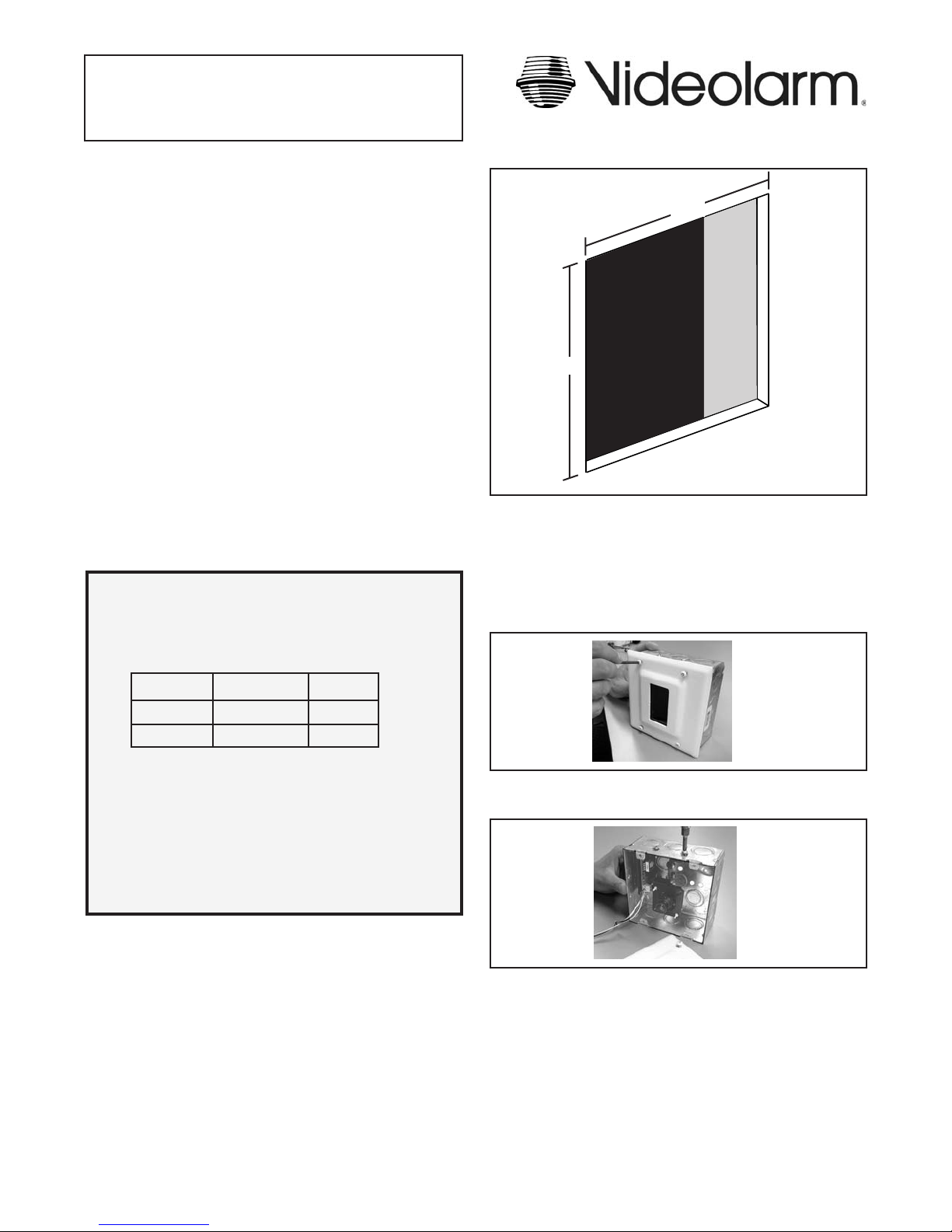
4 3/4"
S
T
U
4 3/4"
Cutout
Figure 1
NOTE: The double-gang box must be fl ush with the drywall.
Two sets of mounting holes are provided on the
sides of the gang box. Use either to ensure that the
box is fl ush with the drywall.
2. Using the security tool provided, loosen the (4) 8-32 security
fasteners and remove the face plate (Figure 2).
D
VOLTAGE CURRENT POWER
12 VDC 350mA 4.2W
24 VAC 202mA 4.8W
Depending on the voltage being used, refer to one of the formulas
below to select the correct power supply for cameras connected in
parallel (positive to positive, negative to negative):
Total current for a 12 VDC system:
TOTAL CURRENT = (350mA x total number of cameras)
Total current for a 24 VAC system:
TOTAL CURRENT = (202mA x total number of cameras)
INSTALLATION PREPARATION
1. Determine the mounting location. Be sure that you’ll be mounting
to a secure wall or ceiling, next to a stud.
2. Complete all wire and conduit runs prior to installation of the
housing.
INSTALLATION PROCEDURE
1. Cut a 4 3/4” x 4 3/4” square hole in the surface with one side
against the stud (Figure 1). If necessary, use the template
provided on the last page of these instructions.
Figure 2
3. Loosen the (2) 8-32 screws holding the top of the camera bracket
and camera in place (Figure 3) and remove.
Figure 3
4. Position the double-gang box in the cutout against the stud and
mark the location of the two mounting holes on the side. Remove
the double-gang box.
5. Determine which side the conduit outlet will be located on: Top,
bottom, left, right, or back. Remove the desired conduit knockout.
CAUTION: TO PREVENT DAMAGE, THE CAMERA AND
BRACKET MUST BE REMOVED BEFORE
TAKING OUT THE CONDUIT KNOCKOUT.
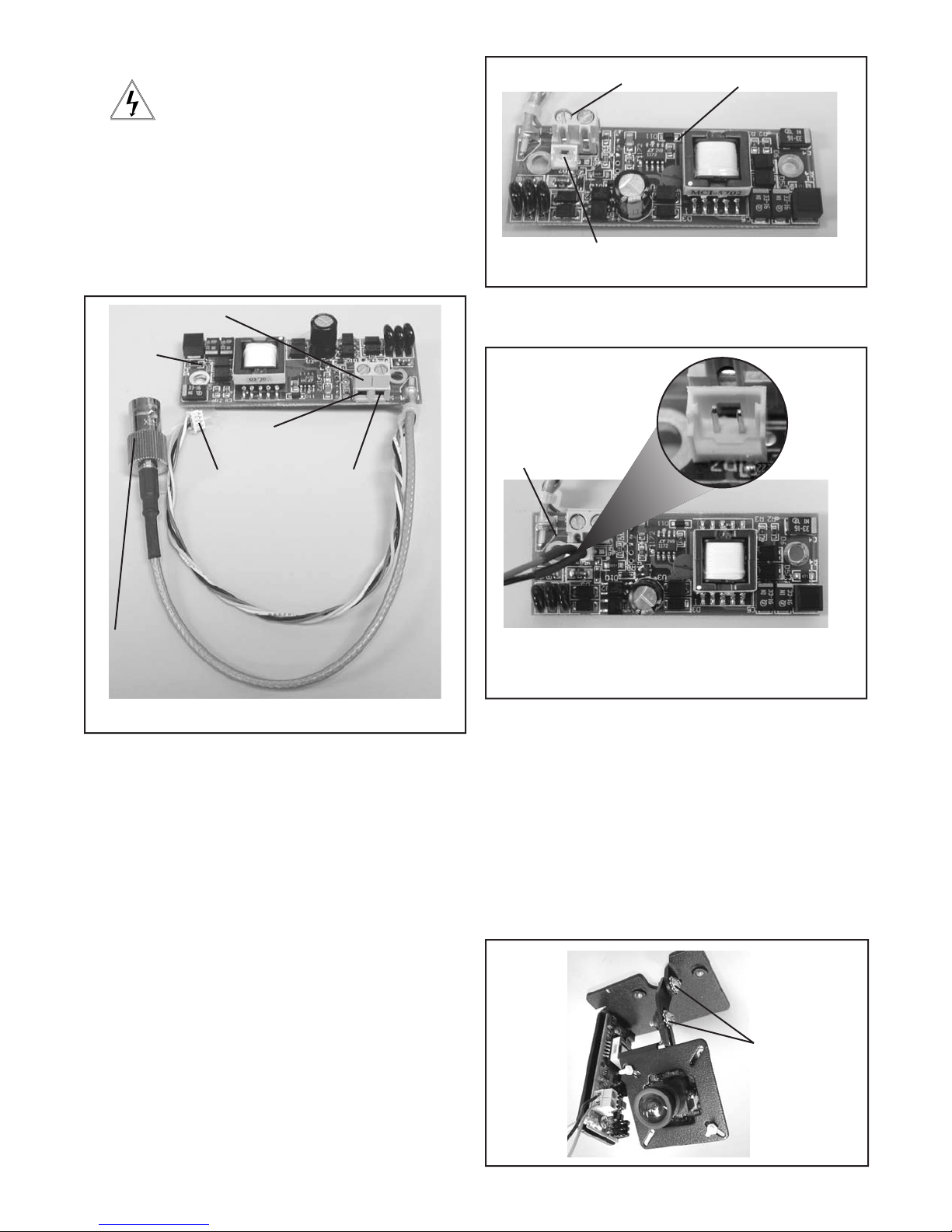
WIRING (Figure 4)
Use Class 2 Power only. Input voltage must be
between 12-28 VDC or 15-28 VAC.
1. Connect the output of your Class 2 Power Supply to the terminal
connectors on the PC Board inside the housing. Refer to the
Troubleshooting section later in this instruction sheet for more
information.
2. Connect the incoming video cable to the BNC connector.
NOTE: For NVT Twisted Pair see Addendum 1.
Te r minal Connector
Test Monitor Cable plug
Figure 5
Power Board
Te r minal Connector
Power
Board
Positive
Connected to
the Camera
Connect to
incoming video
BNC
Figure 4
Negative
OPTIONAL WARRIOR TEST MONITOR CABLE
(Part # - WSTMC)
3. Plug the test monitor cable into the power board (Figure 6).
Attach the BNC connector to your test monitor.
The plug for the Test
Monitor Cable is polarity
protected and can only
be inserted one way.
Test Monitor Cable (NOTE: Your cable may look different)
Figure 6
NOTE: The following instructions are for camera bracket setup,
camera focusing, and camera set-up.
The fi nal steps for installation follow these sections.
DESCRIPTION
The Warrior Test Monitor Cable is a tool that allows users to view
video from cameras via a small on-site monitor. It's quick and
easy to use.
1. Using the security tool provided, loosen the four security
fasteners and remove the housing top. NOTE: The housing
top is held to the base by a lanyard.
2. Locate the power board on the inside of the housing. The Test
Monitor Cable plug is located beside the terminal block where
incoming power is connected (Figure 5).
CAMERA BRACKET SETUP
Reattach the camera bracket to the double-gang box using the
(2) 8-32 screws. Check to determine if the position of the camera is
correct. To adjust the bracket, loosen the (2) 8-32 adjustment screws
(Figure 7). Use Loctite™ or an equivalent product to secure the
screws, especially in installations where vibration is a concern.
8-32
Adjustment
Screws
Figure 7
- 2 -
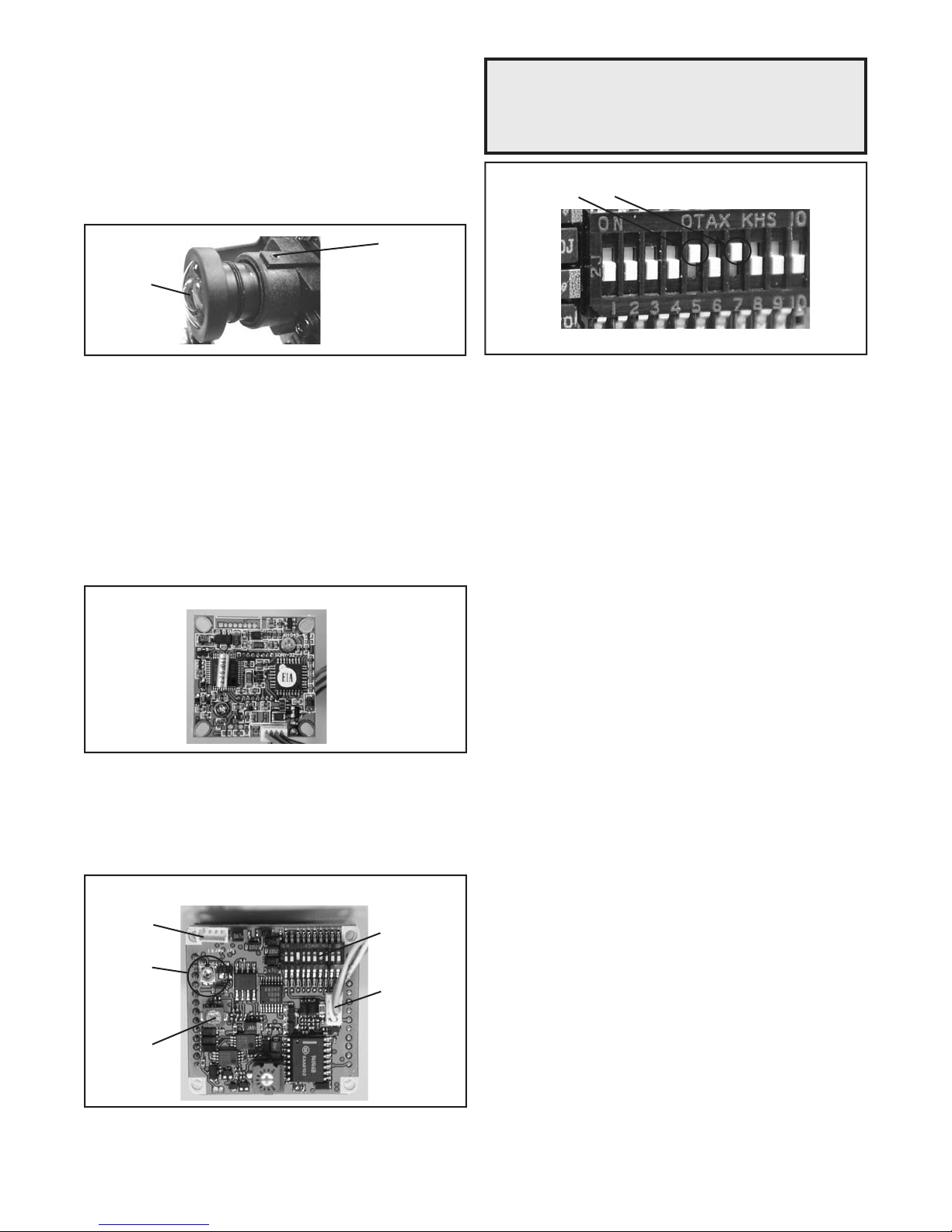
CAMERA FOCUSING (Figure 8)
1. The camera is factory equipped with a 3.6mm fi xed lens. A
2.5mm lens is also provided. To remove the 3.6mm lens, loosen
the set screw and unscrew the lens counter-clockwise.
NOTE: Dip switches are factory pre-set for optimum performance.
In certain specifi c instances it may be necessary to adjust
one or more settings. Consult a qualifi ed technician before
making any adjustments. A Dip Switch settings chart is
available on the next page.
2. Fine focusing of the lens: Loosen the set screw in the lens mount
and manually rotate the lens until a clear picture is achieved. Once
the focus is set, retighten the set screw.
Set screw
Fixed lens
Figure 8
CAMERA SETTINGS
NOTE: To determine which camera is used in your unit, locate the
serial number on the inside of the housing. Match the two
letter prefi x with the corresponding instructions included
here for adjustments.
SERIAL NUMBERS BEGINNING WITH YK
FIXED AND FIXED VARI-FOCAL LENSES. There are no user
adjustable settings on these units (Figure 9).
BW Fixed and Vari-Focal
FACTORY DEFAULT FIXED AND FIXED VARI-FOCAL LENSES:
Dip Switches 5 and 7 on, all others off.
Figure 11
Figure 9
SERIAL NUMBERS BEGINNING WITH MC
The operational settings for the camera are defi ned by ten dip
switches located on the PC Board (Figure 9). Moving the switches to
the on position will activate each setting. Factory defaults are pictured
below (Figure 10).
Hi-Res Color, Fixed and Vari-focal fi xed lenses
Factory
Use Only
Auto Iris
adjustment
screw
DO NOT
ADJUST
Figure 10
Dip Switches
Connection to
Power Board
- 3 -
 Loading...