

Moog Videolarm SView PFD7C12N-3, SView PFD7T12N-3, SView PFD7T12S-3, S-View Pan/Tilt Installation And Operation Instructions Manual

2009-2010, Moog Videolarm, Inc. All Rights Reserved
S - V i e w P a n / Ti l t
Analog and IP
Installation and Operation Instructions for the following model:
Before attempting to connect or operate this product,
please read these instructions completely.
www.videolarm.com
CERTIFIED
81-IN5409
12-06-2010
IMPORTANT SAFEGUARDS SAFETY PRECAUTIONS
1- 800 - 554 -1124
1 Read these instructions.
2 Keep these instructions.
3 Heed all warnings
4 Follow all instructions.
5 Do not use this apparatus near water.
6 Clean only with damp cloth.
7 Do not block any of the ventilation openings. Install in accordance with the
manufacturers instructions.
8 Cable Runs- All cable runs must be within permissible distance.
9 Mounting - This unit must be properly and securely mounted to a supporting
structure capable of sustaining the weight of the unit.
Accordingly:
a. The installation should be made by a qualied installer.
b. The installation should be in compliance with local codes.
c. Care should be exercised to select suitable hardware to install the unit, taking into
account both the composition of the mounting surface and the weight of the unit.
10 Do not install near any heat sources such as radiators, heat registers, stoves, or other
apparatus ( including ampliers) that produce heat.
11 Do not defeat the safety purpose of the polarized or grounding-type plug. A
polarized plug has two blades with one wider than the other. A grounding type
plug has two blades and a third grounding prong. The wide blade or the third
prong are provided for your safety. When the provided plug does not t into your
outlet, consult an electrician for replacement of the obsolete outlet.
12 Protect the power cord from being walked on or pinched particularly at plugs,
convenience receptacles, and the point where they exit from the apparatus.
13 Only use attachment/ accessories specied by the manufacturer.
14 Use only with a cart, stand, tripod, bracket, or table specied by the manufacturer,
or sold with the apparatus. When a cart is used, use caution when moving the cart/
apparatus combination to avoid injury from tip-over.
15 Unplug this apparatus during lighting storms or when unused for long periods of time.
16 Refer all servicing to qualied service personnel. Servicing is required when the
apparatus has been damaged in any way, such as power-supply cord or plug is
damaged, liquid has been spilled of objects have fallen into the apparatus, the
apparatus has been exposed to rain or moisture, does not operate normally, or
has been dropped.
Be sure to periodically examine the unit and the supporting structure to make sure that the integrity
of the installation is intact. Failure to comply with the foregoing could result in the unit separating
from the support structure and falling, with resultant damages or injury to anyone or anything struck
by the falling unit.
CAUTION: TO REDUCE THE RISK OF
ELECTRIC SHOCK, DO NOT REMOVE
COVER ( OR BACK). NO USER- SERVICE-
ABLE PARTS INSIDE. REFER SEVICING
TO QUALIFIED SERVICE PERSONNEL.
The lightning ash with an arrowhead symbol,
within an equilateral triangle, is intended to
alert the user to the presence of non-insulated
“dangerous voltage” within the product’s
enclosure that may be of sufcient magnitude
to constitute a risk to persons.
Este símbolo se piensa para alertar al usuario a la presencia
del “voltaje peligroso no-aisIado” dentro del recinto de los
productos que puede ser un riesgo de choque eléctrico.
Ce symbole est prévu pour alerter I’utilisateur à la presence
“de la tension dangereuse” non-isolée dans la clôture de
produits qui peut être un risque de choc électrique.
Dieses Symbol soll den Benutzer zum Vorhandensein der
nicht-lsolier “Gefährdungsspannung” innerhalb der
Produkteinschließung alarmieren die eine Gefahr des
elektrischen Schlages sein kann.
Este símbolo é pretendido alertar o usuário à presença “di
tensão perigosa non-isolada” dentro do cerco dos produtos
que pode ser um risco de choque elétrico.
Questo simbolo è inteso per avvertire I’utente alla presenza
“di tensione pericolosa” non-isolata all’interno della
recinzione dei prodotti che può essere un rischio di scossa
elettrica
.
The exclamation point within an equilateral
triangle is intended to alert the user to
presence of important operating and
maintenance (servicing) instructions in the
literature accompanying the appliance.
UNPACKING
Unpack carefully. Electronic components can be
damaged if improperly handled or dropped. If an item
appears to have been damaged in shipment, replace
it properly in its carton and notify the shipper.
Be sure to save:
1 The shipping carton and packaging material.
They are the safest material in which to make future
shipments of the equipment.
2 These Installation and Operating Instructions.
Este símbolo del punto del exclamation se piensa para
alertar al usuario a la presencia de instrucciones importantes
en la literatura que acompaña la aplicación.
Ce symbole de point d’exclamation est prévu pour alerter
l’utilisateur à la presence des instructions importantes dans
la littérature accompagnant l’appareil.
Dieses Ausruf Punktsymbol soll den Benutzer zum
Vorhandensein de wichtigen Anweisungen in der Literatur
alarmieren, die das Gerät begleitet.
Este símbolo do ponto do exclamation é pretendido alertar o
usuário à presença de instruções importantes na literatura
que acompanha o dispositivo.
Questo simbolo del punto del exclamaton è inteso per
avvertire l’utente alla presenza delle istruzioni importanti nella
letteratura che accompagna l'apparecchio.
SERVICE
CAUTION
RISK OF ELECTRIC SHOCK
DO NOT OPEN
If technical support or service is needed, contact us at
the following number:
TECHNICAL SUPPORT
AVAILABLE 24 HOURS

LIMITED WARRANTY FOR VIDEOLARM INC. PRODUCTS
PRODUCT WITH RESPECT TO WHICH SUCH CLAIM IS MADE. IN NO EVENT SHALL VIDEOLARM BE LIABLE TO PURCHASER FOR ANY SPECIAL, INDIRECT, INCIDENTAL, OR
VIDEOLARM INC. warrants this Product to be free from defects in material or workmanship,asfollows:
PRODUCTCATEGORY PARTS LABOR
All Enclosuresand Electronics Five (5) Years Five (5) Years
Pan/Tilts Three (3) Years **6 months if usedin autoscan Three (3) Years **6 months if used in autoscan
Poles/PoleEvators Three (3) Years Three (3) Years
Warrior/Q-View/I.R.Illuminators Five (5) Years Five (5) Years
SView Series Five (5) Years
Controllers Five (5) Years Five (5) Years
PowerSupplies Five (5) Years Five (5) Years
AccessoryBrackets Five (5) Years Five (5) Years
During the labor warranty period, to repair the Product,Purchaserwill either return the defective product, freight prepaid, or deliver it to Videolarm Inc.
Decatur GA.The Productto be repaired isto be returned in either its original carton or a similar package
RMA# (Return Materials Authorization number) displayed on the outer box or packing slip. Toobtain a RMA#you must contact our Technical Support
Teamat 800.554.1124,extension 101.Videolarm will return the repaired Product freight prepaid to Purchaser.Videolarm is not obligated to provide
Purchaserwith a substitute unit during the warranty period or at any time. After the applicable warranty period, Purchasermust pay all labor and/or
parts charges.
The limited warranty stated in these product instructions is subject to all of the following terms and conditions:
TERMS AND CONDITIONS
1.NOTIFICATIONOF CLAIMS:WARRANTYSERVICE: If Purchaser believes that the Product is defective in material or workmanship, then written notice
with an explanation of the claim shall be given promptly by Purchaser toVideolarm but all claims for warranty service must be made within the
warranty period. If after investigation Videolarm determines that the reported problem was not covered by the warranty, P
for the cost of investigating the problem at its then prevailing per incident billable rate. No repair or replacement of any Product or part thereof shall
extend the warranty period as to the entire Product. The
following the repair or replacement of that part or the remaining period of the Product parts warranty, whichever is greater.
2.EXCLUSIVE REMEDY: ACCEPTANCE:Purchaser’s exclusive remedy and Videolarm’s sole obligation is to supply (or pay for) all labor necessary to repair
any Product found to be defective within the warranty period and to supply, at no extra charge, new or rebuilt replacements for defective parts.
3.EXCEPTIONS TO LIMITED WARRANTY: Videolarm shall have no liability or obligation to Purchaser with respect to any Product requiring service
during the warranty period which is subjected to any of the following: abuse, improper use: negligence, accident, lightning damage or other acts
of God (i.e., hurricanes, earthquakes),
failure of the end-user to follow the directions outlined in the product instructions, failure of the
end-user to follow the maintenance procedures recommended by the International Security Industry Organization, written in product instructions,
or recommended in the service manual for the Product. Furthermore, Videolarm shall have no liability where a schedule is
replacement or maintenance or cleaning of certain parts (based on usage) and the end-user has failed to follow such schedule; attempted repair by
personnel; operation of the Product outside of the published environmental and electrical parameters, or if such Product’s original
(trademark, serial number) markings have been defaced, altered, or removed. Videolarm excludes from warranty coverage Products sold
AS IS and/or WITH ALL FAULTS and excludes used Products which have not been sold by Videolarm to the Purchaser. All software and accompanying
documentation furnished with, or as part of the Product is furnished “AS IS” (i.e., without any warranty of any kind), except where expressly provided
otherwise in any documentation or license agreement furnished with the Product.
4.PROOF OF PURCHASE:The Purchaser’s dated bill of sale must be retained as evidence of the date of purchase and to establish warranty eligibility.
DISCLAIMEROF WARRANTY
EXCEPT FOR THE FOREGOINGWARRANTIES,VIDEOLARM HEREBY DISCLAIMS AND EXCLUDES ALL OTHER WARRANTIES, EXPRESS OR IMPLIED,
INCLUDING, BUT NOT LIMITEDTO ANY AND/OR ALL IMPLIED WARRANTIES OF MERCHANTABILITY, FITNESS FOR A PARTICULAR PURPOSE AND/OR ANY WARRANTY WITH
REGARD TO ANY CLAIM OF INFRINGEMENTTHAT MAY BE PROVIDED IN SECTION 2-312(3) OF
STATE STATUTE.VIDEOLARM HEREBY DISCLAIMS ANY REPRESENTATIONS ORWARRANTY THAT THE PRODUCT IS COMPATIBLE WITH ANY COMBINATION OF NON-VIDEOLARM
PRODUCTS OR NON-VIDEOLARM RECOMMENDED PRODUCTS PURCHASER CHOOSES TO CONNECT TO PRODUCT.
LIMITATION OF LIABILITY
THE LIABILITY OF VIDEOLARM, IF ANY, AND PURCHASER’S SOLE AND EXCLUSIVE REMEDY FOR DAMAGES FOR ANY CLAIM OF ANY KIND
WHATSOEVER, REGARDLESS OFTHE LEGAL THEORY ANDWHETHER ARISING IN TORT OR CONTRACT, SHALL NOT BE GREATER THAN THE ACTUAL PURCHASE PRICE OF THE
/tour operation
**6 months if usedin autoscan
/tour operation
Five (5) Years
/tour operation
**6 months if usedin autoscan
/tour operation
an equal degree of protection with a
urchaser shall pay Videolarm
warranty on the repaired part only shall be in for a period of ninety (90) days
for regular
THE UNIFORM COMMERCIAL CODE AND/OR IN ANY OTHER COMPARABLE
Electrical Specifications
!!
Class 2 Power Supply Only
MODELS: 24 VAC
S-view: Analog 13 WATTS
S-view: IP 28 WATTS
MODELS: 12VDC
English
S-view: Analog 13 WATTS
S-view: IP 20 WATTS
S-VIEW PAN/ TILT
Fuente De Alimentación De la Clase 2 Solamente.
MODELOS: 24 VAC
S-vista: Análogo 13 VATIOS
S-vista: IP 28 VATIOS
MODELOS: 12VDC
Español
S-vista: Análogo 13 VATIOS
S-vista: IP 20 VATIOS.
Alimentation D'Énergie De la Classe 2 Seulement
MODÈLES : 24 VCA
S-vue : Analogue 13 WATTS
S-vue : IP 28 WATTS
MODÈLES : 12VDC
Français
S-vue : Analogue 13 WATTS
S-vue : IP 20 WATTS.
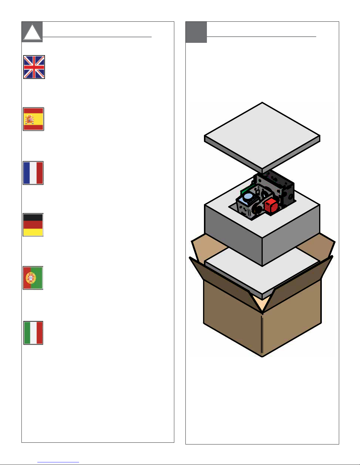
Content of Box
Nur Kategorie 2 Spg. Versorgungsteil
MODELLE: 24 VAC
S-Ansicht: Analog 13 WATT
S-Ansicht: IP 28 WATT
Deutsch
MODELLE: 12VDC
S-Ansicht: Analog 13 WATT
S-Ansicht: IP 20 WATT.
Fonte De Alimentação Da Classe 2 Somente
MODELOS: 24 VAC
S-vista: Análogo 13 WATTS
S-vista: IP 28 WATTS
MODELOS: 12VDC
Portuguese
S-vista: Análogo 13 WATTS
S-vista: IP 20 WATTS
Gruppo di alimentazione Del Codice categoria 2 Soltanto
MODELLI: 24 VCA
S-vista: Analog 13 WATT
S-vista: IP 28 WATT
MODELLI: 12VDC
Italiano
S-vista: Analog 13 WATT
S-vista: IP 20 WATT.
1
2
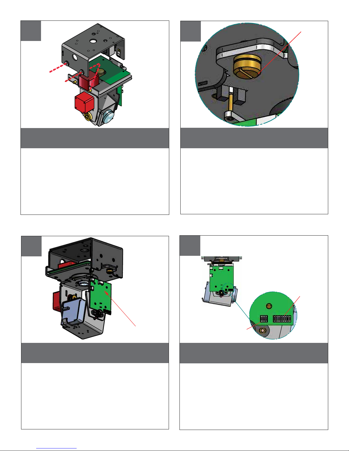
CAPTIVE SCREW
Remove Pan/Tilt from shipping carton.
Install in base bracket in housing.
• Quite Pan/Tilt del cartón del envío. Instale en soporte
bajo en la cubierta.
• Enlevez Pan/Tilt du carton d'expédition. Installez dans
la parenthèse basse dans le logement.
• Entfernen Sie Pan/Tilt vom Verschiffenkarton. Bringen
Sie in niedrigen Haltewinkel im Gehäuse an.
• Remova Pan/Tilt da caixa do transporte. Instale no
suporte baixo na carcaça.
• Rimuova Pan/Tilt dalla scatola di trasporto. Installi in
staffa bassa in alloggiamento.
To secure in place, tighten captive screw.
• Para asegurar en lugar, apriete el tornillo prisionero.
• Pour fixer en place, serrez la vis captive.
• Um im Platz zu sichern, ziehen Sie Sicherheitsschraube
fest.
• Para fixar-se no lugar, aperte o parafuso prisioneiro.
• Per fissare sul posto, stringa la vite prigioniera.
43
Address Dip
?
Switches
To set camera address locate PC board on
the side of Pan/Tilt unit. (Analog)
• Para fijar la dirección de la cámara fotográfica localice
el tablero de PC en el lado de la unidad de Pan/Tilt.
• Pour placer l'adresse d'appareil-photo localisez le
panneau de PC du côté de l'unité de Pan/Tilt.
• Um Kameraadresse einzustellen lokalisieren Sie PC Brett
auf der Seite der Pan/Tilt Maßeinheit.
• Para ajustar o endereço da câmera encontre a placa
de PC no lado da unidade de Pan/Tilt.
• Per regolare l'indirizzo della macchina fotografica
individui il bordo del pc dal lato dell'unità di Pan/Tilt.
PC Board
located here
Factory Settings
DO NOT ADJUST
Use the 8 position Dip switch to set address
lower corner. (Analog)
• Utilice el interruptor dip de 8 posiciones para fijar una
esquina más baja de la dirección.
• Utilisez le contact DIP de 8 positions pour placer le
coin inférieur d'adresse.
• Benutzen Sie den 8 Position DIP-Schalter, um Adresse
unterere Ecke einzustellen.
• Use o interruptor de mergulho de 8 posições ajustar
um canto mais baixo do endereço.
• Utilizzi l'interruttore di tuffo di 8 posizioni per regolare il
angolo più basso di indirizzo.
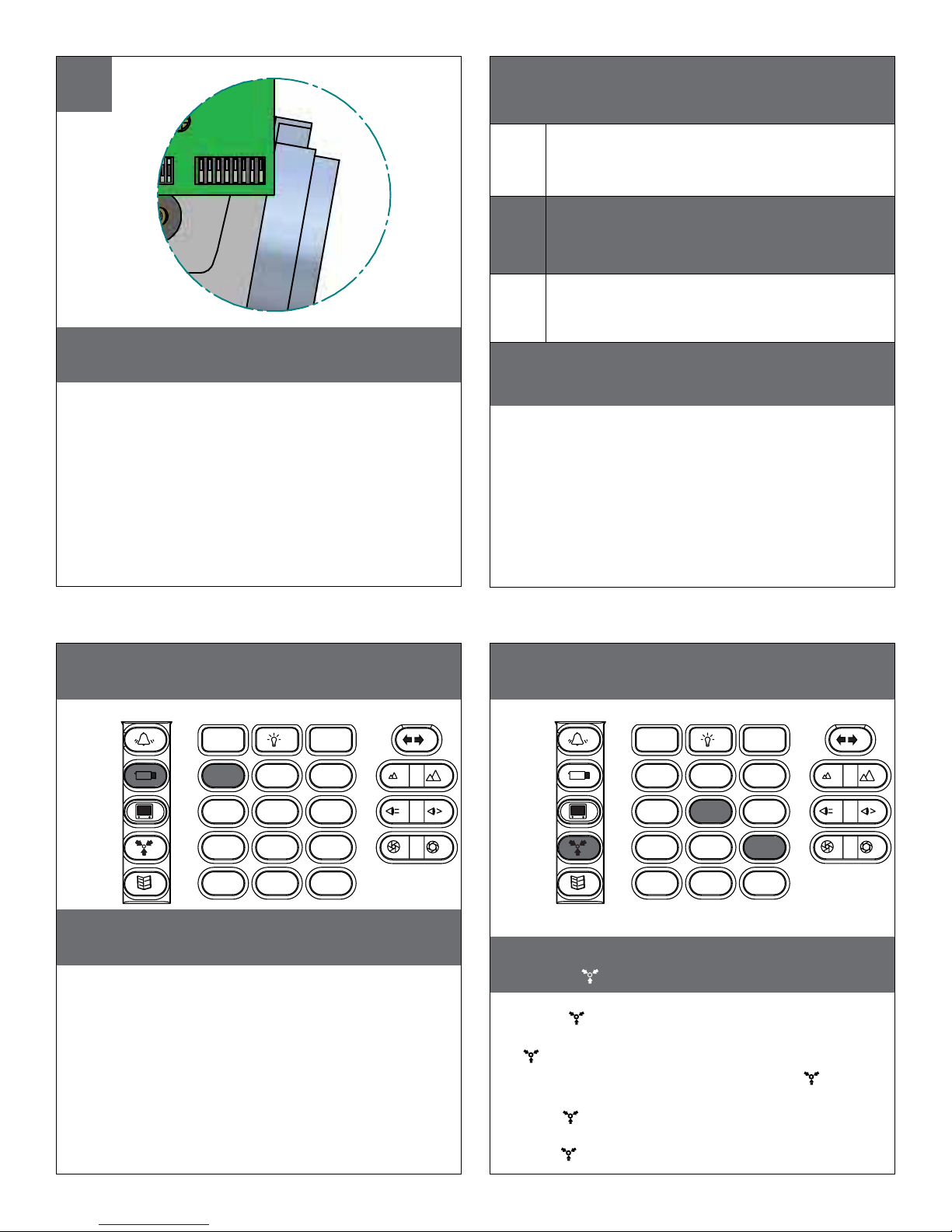
5
(Analog)
6
PROTOCOLS
ON
OFF
To set the address at “0” side the all switches off
as shown. See table in back for address 0-255
• Para fijar la dirección en "0" lados todos los interruptores
apagado según lo demostrado. Vea la tabla adentro detrás
para la dirección 0-255
• Pour placer l'adresse sur "0" côtés les tous les commutateurs
au loin comme montré. Voir le tableau dedans en arrière
pour l'adresse 0-255
• Die Adresse an "0" Seite weg einstellen die alle Schalter, wie
gezeigt. Sehen Sie Tabelle innen zurück für Adresse 0-255
• Para ajustar fora o endereço em "0" lados todos os interruptores como mostrado. Veja a tabela dentro para trás para o
endereço 0-255
• Per regolare l'indirizzo "su 0" lati tutti gli interruttori fuori come
indicato. Veda la tabella dentro indietro per l'indirizzo 0-255
1 VL422
2 PELCO P 4800/9600
3 PELCO D 4800/9600
The S-View Pan/Tilt support the above protocols.
This is done automatically no settings are
required.
• La ayuda de la S-Vista Pan/Tilt los protocolos antedichos. Se
requiere esto se hace automáticamente ningunos ajustes.
• L'appui de la S-Vue Pan/Tilt les protocoles ci-dessus. Ceci est
fait automatiquement aucuns arrangements sont exigés.
• Die S-Ansicht Pan/Tilt Unterstützung die oben genannten
Protokolle. Diesem wird automatisch keine Einstellungen
werden angefordert getan.
• A sustentação da S-Vista Pan/Tilt os protocolos acima. Isto é
feito automaticamente nenhuns ajustes é requerido.
• Il supporto di S-Vista Pan/Tilt i suddetti protocolli. Ciò è fatta
automaticamente nessun regolazioni è richiesta.
7
Camera
MENU DRIVEN SETTINGS (Analog)
1, 2, 3...
1
4
7 8
*
2
5
0
F
3
6
9
#
When using Videolarm controller; to enter the
menu; select the camera you wish to control.
• Al usar el regulador de Videolarm; para incorporar el menú;
seleccione la cámara fotográfica que usted desea controlar.
• En utilisant le contrôleur de Videolarm ; pour écrire le menu ;
choisissez l'appareil-photo que vous souhaitez commander.
• Wenn Videolarm Steuerpult verwendet wird; das Menü
eintragen; wählen Sie die Kamera vor, die Sie steuern
möchten.
• Ao usar o controlador de Videolarm; para incorporar o
menu; selecione a câmera que você deseja controlar.
• Nel usando il regolatore di Videolarm; per entrare nel menu;
selezioni la macchina fotografica che desiderate controllare.
8
Presets
MENU DRIVEN SETTINGS (Analog)
1, 2, 3...
1
4
7 8
*
2
5
0
F
3
6
9
#
Then press 95 followed by the Preset
button ( ).
• Entonces la prensa 95 siguió por preestableció el
botón ( ).
• Alors la pression 95 a suivi de a préréglé le bouton
( ).
• Dann folgte Presse 95 von einstellte Taste ( ).
• Então a imprensa 95 seguiu pelo pré-ajustou a
tecla ( ).
• Allora la pressa 95 è seguito dal ha prestabilito il
tasto ( ).
 Loading...