

Moog Videolarm RH7 Instruction Manual
© 2009, Videolarm, Inc. All Rights Reserved
RH7
Rugged Housing Vandal-Resistant Series
Installation and Operation Instructions for the following models:
Before attempting to connect or operate this product,
please read these instructions completely.
CERTIFIED
81-IN5300
02-02-2009
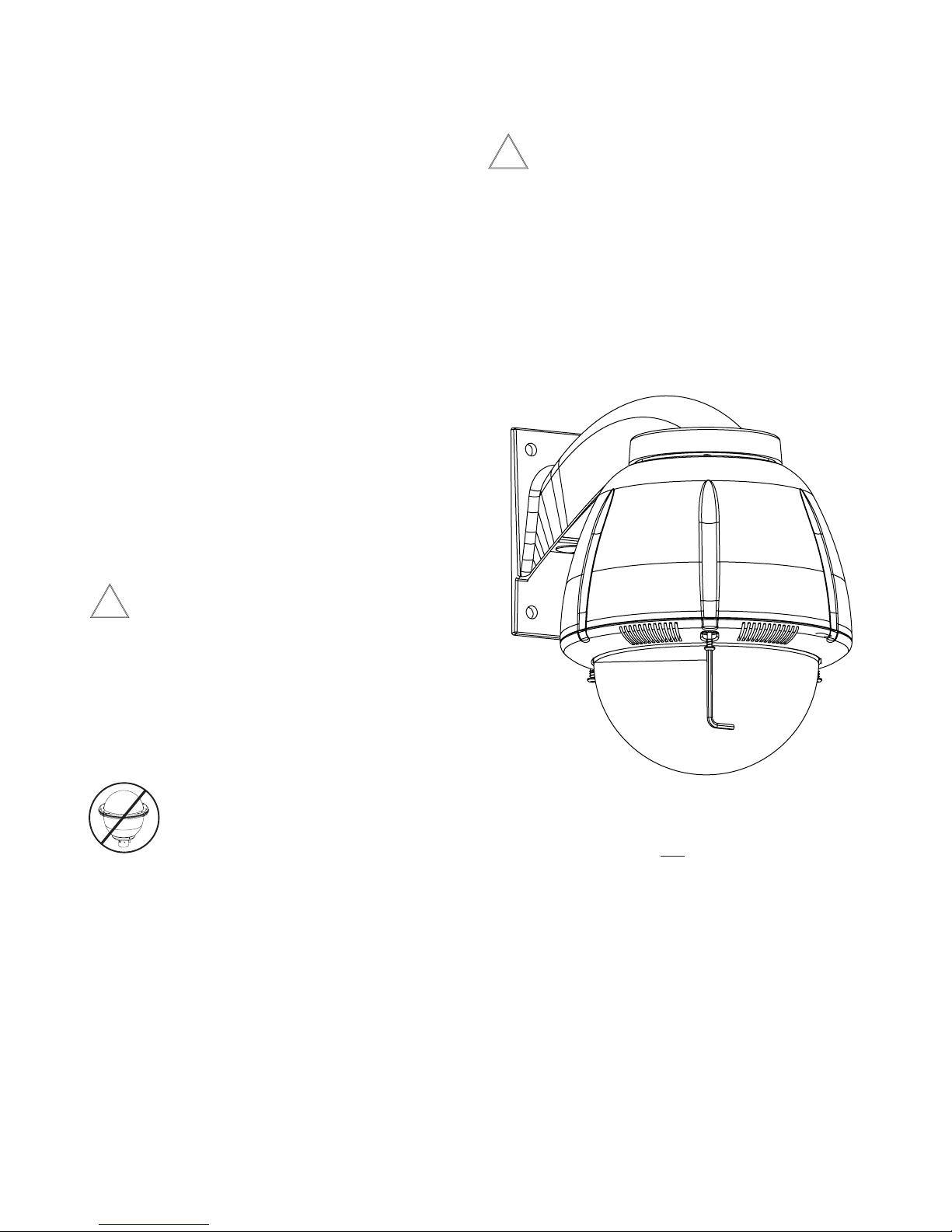
TABLE OF CONTENTS
Description 1
Electrical Specifications 1
Parts List 1
Installing Quick Release Bracket 1
Installing the Housing Assembly 1
Installing Optional Pendant Mount 2
Wiring Color Code Chart 2
Instructions for Quick Release Brackets 4
Exploded View 5
Exploded View for Replacement Parts 6
Mounting Template 8
Safeguards and Warranty Information 9
DESCRIPTION:
The RH7C Housing is a Vandal Resistant Housing especially
designed for integrated pan/tilt units. The housing top is made of
high impact resistant cast aluminum while lower dome is made of an
optically clear, UV stable, polycarbonate plastic. The RH7C housing
measures 9.75” (w) x 13 (h) and 14.5” (d) with a weight of 8.25 lbs.
Flying leads are provided for all power, control and video connec-
tions. The leads are supplied with a standard BNC and (2) screw
down connectors. Two 25W heater (50 watts total) with (2) circula-
tion fans also supplied.
GENERAL INSTRUCTIONS:
Tools Required: .100" Flat Head Screwdriver
Phillips Head Screwdriver
Be sure the bracket is properly and securely mounted to a
supporting structure capable of rigidly holding the weight of
!
the entire unit.
INSTALLING QUICK RELEASE BRACKET AND PAN/TILT
CAMERA ASSEMBLY (ALL MODELS)
1. Open the housing by loosening the (3) tamper proof screws
located on the housing ring next to the lower clear dome
(Figure 1). Be careful not to back these all the way out. Twist the
dome slightly in a counterclockwise motion until it stops, then pull
down to remove.
Figure 1
ELECTRICAL SPECIFICATIONS (OUTDOOR ONLY):
Power 24VAC, Class 2 Only
!
52 watts at 24 VAC (accessories)
Heater: 50 watts
Blower: 2 watts
Input Connectors (outdoor units):
BNC
(2) screw-down connectors
NOTE: This unit is designed for operation in an upright
position. Installing the RH7™ upside down may
cause damage to the internal equipment, and
will void the warranty.
PARTS LIST
Check to be sure the following parts are included.
1. Housing
2. Housing Packet
a. (2) Mates for screw down connectors (not supplied with
indoor units)
b. (1) Adapter plate
c. (8) 1/2" standoffs
d. (8) 8 x 32 x 3/8" Mounting screws with star washers
e. (3) 6 x 32 x 3/8" Mounting screws with star washers
f. (2) 1/4 x 20 x 3/8" HH Bolts
g. (2) 1/4” Flat washers
h. (2) 1/4" Split Lock washers
i. Instruction Manual
Loosen screws only,
do not remove
Remove dome by twisting
counter-clockwise until it
stops, then pull down
2. Install the pan/tilt unit quick-release bracket. It is recommended
that this be done before installing the housing. Instructions for
mounting quick-release brackets from selected manufacturers are
on page 4.
3. Clean the inside of the dome. Reattach the housing dome and
secure the (3) captive screws. Do not overtighten the screws.
Tighten only to the point at which the gap between the ring and
the housing top closes.
- 2 -
INSTALLING THE HOUSING ASSEMBLY
FOR WALL MOUNT, RH7C
A wall mount bracket comes standard with this unit, and a
template is included to use as a guide for mounting the bracket
to a wall. Choose the desired location for installation and mark
the drill holes using the template. Screw (2) bolts (not
provided) about 3/4 of the way into the (2) top holes. Run
approximately 8" of wiring out of the wall.
NOTE: Be sure the hardware and the mounting surface can sup-
port the weight of the wall mount bracket plus the weight
of the housing and drive unit. The load will be subjected
to vibration from the camera motor and wind.
2. The wall mount bracket provided with the rugged housing includes
a location for conduit entry. If you wish to install conduit to the
bracket remove the conduit hole plug. Install fitting from below the
wall mount and secure with conduit nut from inside the bracket.
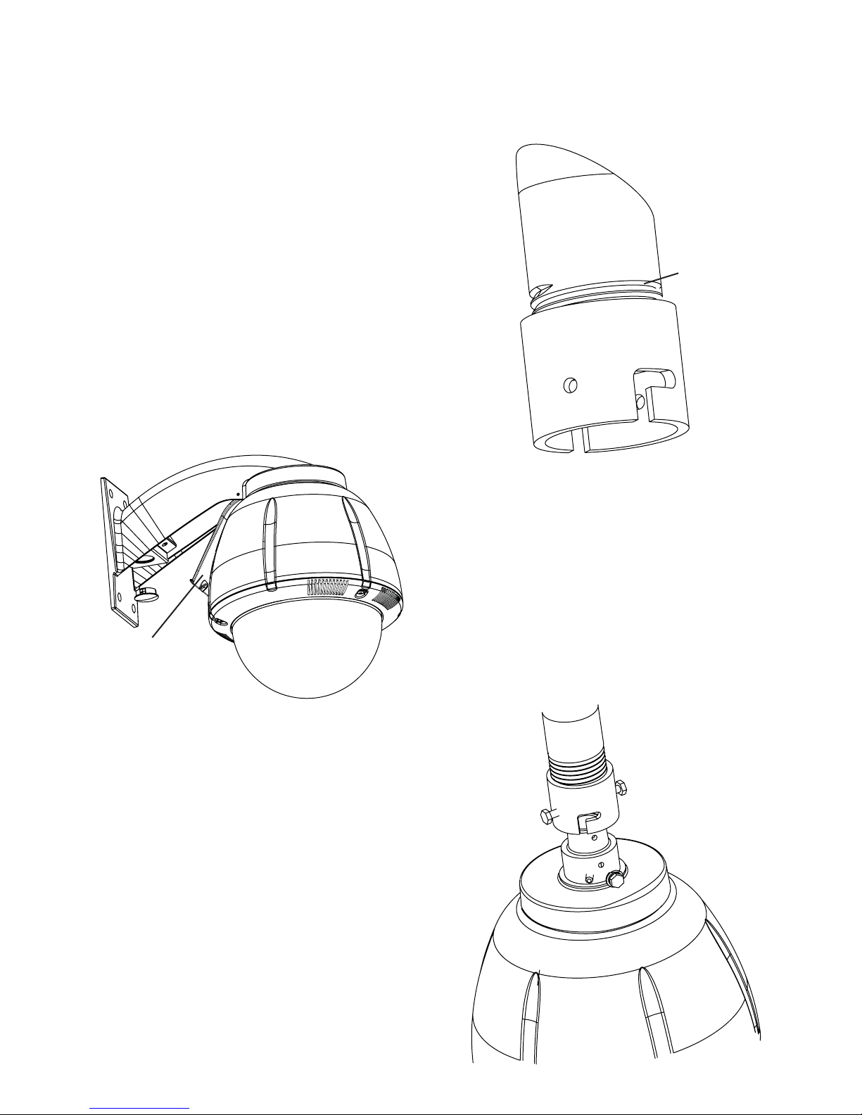
3. Open the access door on the bottom of the wall mount by
loosening the screw nearest the mounting plate (Figure 2).
2. Attach the housing coupling (Figure 3).
NOTE: Pipe threads should be clean and rust free. Use a
sealer (such as Teflon™ tape or silicone sealer) on the
threads.
Add thread
sealing tape
Figure 3
Access panel
Figure 2
4. Attach the wires from the wall to the connector provided, using the
wiring color code chart as a guide.
5. Once all wiring connections are made, place the wires inside the
wall mount bracket and close the access door. Secure with the
screw removed earlier.
6. Clean the outside of the dome.
1. Mount the housing assembly to the mounting bracket and
housing coupling. A safety cable is included with the housing to
temporarily hold it while making wiring connections. Loop the
safety cable over one of the set screws on the housing coupling
and make the appropriate connections using the (2) screw-down
connectors supplied.
2. Undo the safety cable and twist the housing onto the housing
coupling. Secure all (3) setscrews provided on the housing
coupling (Figure 4).
3. Clean the outside of the dome.
Twist and
Secure
Figure 4
FOR OPTIONAL PENDANT MOUNT
1. This unit includes a 1 1/2" NPT housing for a standard 1 1/2"
NPT pipe. The RH7C can be used with other brackets
designed with 1 1/2" male pipe threads, such as the Videolarm
WM20G and WM20 wall mount brackets.
- 3 -
22
250
120
89
65
44
35
29
25
31
19
17
16
14
13
12
11
11
10
9
9
8
20
400
180
141
90
70
56
47
40
34
31
28
25
23
21
20
18
17
16
15
14
14
18
600
300
225
130
112
90
75
64
55
50
45
41
37
34
32
30
28
26
25
23
22
16
960
480
358
225
179
143
119
102
85
79
71
65
59
55
51
47
44
42
39
37
35
14
-
800
571
350
285
228
190
163
140
126
114
103
95
87
81
76
71
67
63
60
57
12
-
1300
905
525
452
362
301
258
215
201
181
164
150
139
129
120
113
106
100
95
90
10
-
-
1440
830
720
576
480
411
340
320
288
261
240
221
205
192
180
169
160
151
144
5.5
10
20
30
40
50
60
70
80
90
100
110
120
130
140
150
160
170
180
190
200
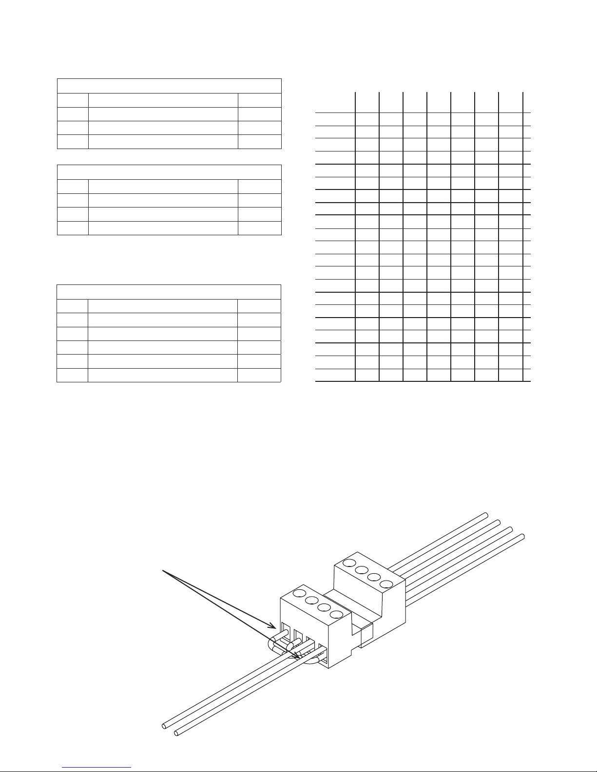
Maximum distance from transformer to load
Total vA
consumed
Wire Gauge
24k VAC Wiring Distances
The following are the recommended maximum distances for 24 VAC
with a 10% voltage drop (10% is generally the maximum allowable
voltage drop for AC powered devices).
Wiring Color Code
Power and Control Inputs
(Outside of housing)
POWER
1 Camera Power (24 VAC) Red
2 Camera Power (24 VAC) Orange
3 Accessory Power (24 VAC) Yellow
4 Accessory Power (24 VAC) Green
CONTROL
1 RS-485RXB Blue
2 RS-485RXA Violet
3 RS-485TXA Gray
4 RS-485TXB White
Power and Control Outputs
(Inside of housing)
POWER AND CONTROL LEADS
1 Camera Power (24 VAC) Red
2 Camera Power (24 VAC) Orange
3 RS-485RXB Blue
4 RS-485RXA Violet
5 RS-485TXA Gray
6 RS-485TXB White
The unit is setup with (2) individual power inputs.
1. Accessory Power (yellow and green wire)
2. Camera Power (red and orange)
If you wish to provide a single power transformer it is recommended that:
1. Be certain that you know the total power consumption of the
housing Heater (50 watts) + Blower (2 watts) + camera/pan-tilt
(not supplied)
2. Check the supplied wiring chart to be sure that you have the
Figure 5
Add 2 jumpers for
single power input
proper gauge wire for the distance that you intend to run your
power wires.
3. Bring power to the 3 and 4 position of the power connector (yellow
and green wire)
4. Two jumpers are provided in the housing packet. Jumper from
st
position to the 3rd position and from the 2nd position to the
the 1
th
4
position of the terminal block. Be careful not to short between
the yellow and green wires.
-4 -
 Loading...